

Research on Power Optimization for Energy System of Hydrogen Fuel Cell Wheel-Driven Electric Tractor
1
College of Vehicle and Traffic Engineering, Henan University of Science and Technology, Luoyang 471003, China
2
State Key Laboratory of Intelligent Agricultural Power Equipment, Luoyang 471039, China
3
YTO Group Corporation, Luoyang 471004, China
*
Author to whom correspondence should be addressed.
World Electr. Veh. J. 2024, 15(5), 188; https://doi.org/10.3390/wevj15050188
Submission received: 18 March 2024
/
Revised: 21 April 2024
/
Accepted: 25 April 2024
/
Published: 28 April 2024
(This article belongs to the Special Issue New Energy Special Vehicle, Tractor and Agricultural Machinery)
Abstract
:Hydrogen fuel cell tractors are emerging as a new power source for tractors. Currently, there is no mature energy management control method available. Existing methods mostly rely on engineers’ experience to determine the output power of the fuel cell and the power battery, resulting in relatively low energy utilization efficiency of the energy system. To address the aforementioned problems, a power optimization method for the energy system of hydrogen fuel cell wheel-driven electric tractor was proposed. A dynamic model of tractor ploughing conditions was established based on the system dynamics theory. From this, based on the equivalent hydrogen consumption theory, the charging and discharging of the power battery were equivalent to the fuel consumption of the hydrogen fuel cell, forming an equivalent hydrogen consumption model for the tractor. Using the state of charge (SOC) of the power battery as a constraint, and with the minimum equivalent hydrogen consumption as the objective function, an instantaneously optimized power allocation method based on load demand in the energy system is proposed by using a traversal algorithm. The optimization method was simulated and tested based on the MATLAB simulation platform, and the results showed under ploughing conditions, compared with the rule-based control strategy, the proposed energy system power optimization method optimized the power output of hydrogen fuel cells and power batteries, allowing the energy system to work in a high-efficiency range, reducing the equivalent hydrogen consumption of the tractor by 7.79%, and solving the energy system power distribution problem.
1. Introduction
The International Energy Agency’s “World Energy Outlook 2022” points out it is still very important to promote the energy revolution and build clean, low-carbon, safe, and efficient energy [1]. Hydrogen, although not an energy source itself, has gained extensive utilization as a readily available, environmentally friendly, and low-carbon secondary energy carrier. Hydrogen, being colorless and odorless, and exhibiting no toxic effects on humans or ecology [2], is emerging as a significant contributor to the global energy transition and development. It serves as one of the key carriers for sustainable energy advancement worldwide [3]. With the development of clean hydrogen production technologies such as water electrolysis, a hydrogen fuel cell (FC) utilizes carbon-free hydrogen as fuel during operation, with water being the main reaction product. This positions FC as a promising, important, and clean energy conversion technology for the future. Furthermore, since an FC operates based on electrochemical reactions converting chemical energy into electrical energy, its reaction process does not involve combustion. Therefore, the energy conversion efficiency is not constrained by the limitations of the Carnot cycle [4,5], making it an ideal source of energy for power machinery.
There are few known studies on energy management of hydrogen FC tractors, mainly focusing on road vehicles [6,7]. Energy management approaches can be classified into two distinct categories: rule-based energy management and optimization-based energy management methodologies [8,9,10]. The rule-based energy management method can design power allocation rules based on expert experience and operational knowledge, so that the FC can operate in a high-efficiency range as much as possible. The main implementation methods include fuzzy logic, finite state machine, and power following [11]. To protect FCs and ensure their efficiency, Shen et al. [12] propose a fuzzy control energy management strategy that takes into account the characteristics of FCs. This strategy aims to achieve stable and efficient output from the FCs. However, it does not consider the state of charge (SOC) of the power battery. Considering the influence of the power battery SOC and the supercapacitor state voltage on its performance, Wen et al. [13] proposed an energy management strategy based on a “thermostat”, which could maintain the power battery SOC and improve the whole machine economy. However, this method is not suitable for scenarios with more complex operating conditions. In response to this, Wang et al. [14] proposed a management strategy for the battery/supercapacitor/fuel cell system based on an effective state machine, which improved the power density of the power system and the net output power of the FC; it is capable of meeting the power requirements of most driving conditions. However, although rule-based energy management strategies have the advantages of low technical difficulty and small online computing volume, it is difficult to achieve control effects close to optimal. The optimization-based energy management methods optimize the target through optimization algorithms to make vehicle operation more energy-efficient. To realize the reasonable distribution of energy between different energy sources, Wang et al. [15] combined the dynamic programming global optimization method with fuzzy logic control to reduce the hydrogen consumption of the whole machine and improve the efficiency of the FC. However, this method has the issue of cumulative errors in battery SOC estimation. To solve this problem, Song et al. [16] proposed an FC vehicle energy management strategy based on dynamic programming, which improved the energy system efficiency and reduced the error accumulation in the control process. This dynamic programming algorithm has a large amount of calculations and takes a long time. Therefore, Zhou et al. [17] proposed a fast and unified method for solving dynamic programming problems, which effectively reduced the calculation time while reducing the energy consumption of the whole machine. Global optimization can greatly improve the energy-saving effect of the system, but it requires a large amount of calculation and has poor real-time performance. Instantaneous optimization can perform real-time optimization within the sampling period. Compared with global optimization, it has the advantages of smaller number of calculations and higher real-time performance. Therefore, it is an ideal online optimization method [18]. Zhou et al. [19] used a Markov pattern recognizer to divide driving modes into three types and used a multi-mode predictive controller to formulate a control strategy, which ensured the safe and stable operation of the FC while improving economy. This method did not consider the SOC of the power battery. Wang et al. [20] proposed an energy management strategy based on the Pontryagin’s minimum principle, which can ensure both overall economy and stable SOC, but it cannot adapt to the dynamic changes in complex traffic environments. To solve this problem, Nie et al. [21] used the model predictive control method to carry out the energy scheduling of hybrid systems, which can effectively optimize driving performance and improve economy. In the field of non-road vehicles, there are few known studies on hydrogen FC power distribution. Regarding the energy management strategy of tractors, Xu et al. [22] developed an energy management strategy based on fuzzy control for FC power battery hybrid tractors; the simulation results showed this strategy reduced the depth of discharge of the dynamic battery and decreased the equivalent hydrogen consumption of the tractor, but this method also did not consider the impact of load on the strategy.
The joint operation of power batteries and hydrogen fuel cells to drive tractors, and determining the power distribution between the two, is crucial to achieving efficient operation of the energy system, representing an urgent problem that needs to be addressed. Traditional rule-based optimization strategies often directly determine a fixed proportion factor for the power allocation between the power battery and hydrogen fuel cell, which makes it difficult to achieve efficient output of the energy system. Furthermore, the load is crucial for the power allocation within the energy system of hydrogen fuel cell tractors. To tackle the challenge of instantaneous power optimization in hydrogen fuel cell electric tractors, this paper focuses on hydrogen fuel cell wheel-drive electric tractors. By integrating dynamics and the theory of equivalent hydrogen consumption, and introducing a charge retention strategy, a load-demand-based instantaneous optimization method for power allocation within the energy system is proposed, aiming to effectively distribute power between the power battery and hydrogen fuel cell. The main contributions of this paper are as follows: a real-time power allocation method based on instantaneous optimization is proposed to address the power allocation challenges faced by hydrogen fuel cell tractors under time-varying conditions.
The subsequent sections of this paper follow the following structure: in Section 2, the topology structure and main technical parameters of the hydrogen FC electric tractor are introduced. Section 3 models the main components of the tractor. In Section 4, an instantaneously optimized power allocation method based on load demand is proposed for the energy system. Section 5 conducts strategy verification on the MATLAB/Simulink simulation platform. Finally, Section 6 presents the research conclusions.
2. Tractor Topology Structure and Main Parameters
2.1. Hydrogen Fuel Cell Wheel-Driven Electric Tractor Topology Structure
Hydrogen FCs use carbon-free hydrogen as fuel and have advantages such as high energy density, long service life, clean and pollution-free process. Tractors that use hydrogen fuel cells/power cells effectively integrate the advantages of high-power density in power batteries with the high energy density in FCs, which is one of the directions for future research on energy-saving and environmentally friendly tractors.
The topology structure of the hydrogen FC wheel-driven electric tractor is shown in Figure 1. The tractor has two energy sources, hydrogen FCs and batteries. The output torque of the wheel-driven motor is directly transmitted to the drive wheel through the reducer.
The vehicle control unit is connected to the hydrogen FC, battery, DC/DC module, DC/AC module, and two wheel-side driven electric motors through the Controller Area Network (CAN) bus. According to the power demand of the whole machine and the power battery SOC, the output power of the FC and the battery is dynamically allocated according to the power optimization method of the energy system, thereby enabling the tractor to achieve optimal power performance and economy.
2.2. Main Technical Parameters of Hydrogen Fuel Cell Wheel-Drive Electric Tractor
Expanding upon the preceding research findings of the research group, the main technical parameters of the hydrogen FC wheel-driven electric tractor used in this study are shown in Table 1.
3. Hydrogen Fuel Cell Tractor Model Construction
The key components of a hydrogen FC tractor include the hydrogen FC, power battery, motor, etc. The tractor model forms the foundation for the control of the entire machine. Therefore, the model established in this section includes the dynamics model, transmission system model, hydrogen FC model, power battery model, motor model, tyre model, and whole machine simulation mode.
3.1. Tractor Dynamics Model
By conducting the analysis of the tractor’s driving force and driving resistance, the condition for the tractor to operate normally is the driving force equals the sum of all driving resistances. When the tractor is working in the field, the load of towing agricultural machinery is very large. Therefore, the driving resistance includes the resistance that must be overcome when towing agricultural machinery, that is, the towing resistance FTN. Since the operating velocity of the tractor is low and close to uniform, the air resistance and acceleration resistance can be ignored [23]. Therefore, the driving equation for the ploughing condition of the tractor can be expressed as:
where Ft is the total driving force, N. Ff is the rolling resistance, N. FTN is the rated traction resistance, N.
During field operations, ploughing is a common high-load operation, so the driving force of the tractor should meet the needs of the tractor’s ploughing operation. Considering the large load fluctuations caused by the working conditions of the tractor and the changes in the performance of agricultural machinery, a reserve of 10~20% should be left [24]. Therefore, the rated traction force when the tractor is ploughing is:
where FTa is the ploughing resistance, N.
The required torque and speed of the drive wheel during the hydrogen FC wheel-drive electric tractor ploughing operation are:
where Tq is the torque required for the drive wheels, N·m. nq is the required speed of the drive wheels, rpm. v is the tractor velocity, m/s. And, r is the driving wheel radius, m.
3.2. Transmission System Model
The transmission system of wheel-driven tractors mainly consists of wheel-side reducers, which belong to the gear transmission mechanism. Unlike urban vehicles that require frequent gear shifting, tractors experience relatively small variations in operating speeds during field work. Therefore, this paper simplifies the transmission system model to a fixed gear ratio gear model [25]:
where Treqm is the required torque of the motor, N·m. nreqm is the required speed of the motor, rpm. And, i is the speed ratio of the wheel-side reducer.
3.3. Motor Model
The motor uses a permanent magnet synchronous motor. Compared with other motors, the permanent magnet synchronous motor has advantages such as good reliability, high work efficiency, large torque, small size, and light weight. It can cope with the relatively complex operating environment when the tractor is working in outdoor fields. The efficiency model of the motor can be determined by establishing a quasi-static graph of output speed and torque. Subsequently, the efficiency of the motor can be obtained by referring to a table. The relationship between motor efficiency, speed, and torque is as follows:
where ηm is the motor efficiency, %. nm is the motor speed, rpm. And, Tm is the motor torque, N·m.
The required driving power (Preqm) of the motor is:
where Preqm is expressed in kW.
When calculating the efficiency of the drive motor, since the trend of the motor’s electric efficiency and power generation efficiency is similar, it is assumed in the model building that the power generation efficiency and electric efficiency of the permanent magnet synchronous motor used are the same. The efficiency numerical model of the permanent magnet synchronous motor used in this paper is shown in Figure 2.
3.4. Power Battery Model
The Rint model [26] is a common equivalent circuit model. The battery is modeled as an ideal voltage source connected in series with an internal resistance. The structure is simple, and the parameters are easy to identify, making it suitable for whole vehicle energy management algorithms. In the Rint model, the effects of temperature on the battery pack are ignored. The open circuit voltage and charge-discharge internal resistance of the battery are affected by the state of charge (SOC) and the charge-discharge current of the battery.
In accordance with the Rint model [27,28] of the battery, the power of the battery, denoted as Pbat, can be expressed by the following equation:
where Pbat is the battery power, kW. Voc is the battery open circuit voltage, V. Rint is the battery internal resistance, Ω. And, Ibat is the battery current, A.
The SOC of the battery can be represented by the ampere-hour method [29] as follows:
where Qbat is the battery rated capacity, A·h.
The instantaneous discharge efficiency/charge efficiency, denoted as ηdis and ηchg, of the battery [30] can be represented as follows:
where ηdis is the instantaneous discharge efficiency of the battery, %. And, ηchg is the instantaneous charge efficiency of the battery, %.
Substituting (8) into (10) yields the following result:
3.5. Hydrogen Fuel Cell Model
Hydrogen FCs convert the chemical energy in hydrogen into electricity and are a clean and efficient power generation device. This paper uses the proton exchange membrane fuel cell (PEMFC), which is widely used in engineering, and has the advantages of fast cold start and high energy conversion rate and can be used as a mobile power supply. Hydrogen FC models can be divided into mechanism models and numerical models. Although the mechanism model has good dynamic response, the model is more complex and requires a large amount of calculation. The operating characteristics of the hydrogen FC system used in this paper are shown in Figure 3, which shows the optimal operating area of the hydrogen FC system is within 10% to 80% of its power range.
Through polynomial fitting, the voltage model of the FC is obtained as follows:
where Vfc is the FC output voltage, V. Pfc is the FC system power, kW. ξj is the fitting parameters, j = 1, 2, 3, 4.
In practical use, a hydrogen FC requires auxiliary equipment to support its operation. The auxiliary equipment mainly includes air circulation pumps, cooling water circulation pumps, exhaust fans, hydrogen supply pumps, and electronic control equipment. The efficiency decreases at high power because a larger voltage drop occurs in the hydrogen FC stack at high power. On the other hand, the lower efficiency at low power is due to the increased percentage in energy consumed by auxiliary equipment at low power [31]. The hydrogen FC efficiency used in this paper is fitted by polynomial and yielded as follows:
where ηfc is the FC system efficiency, %. And, γj is the fitting parameters, j = 1–9.
3.6. Tyre Model
Commonly used tyre models include theoretical models such as the Gim model and Finala model, as well as empirical or semi-empirical models such as the power exponential formula, semi-empirical model, UniTire model, and magic tyre model [32]. The magic formula model not only has a simple structure but also has high simulation accuracy. Its general expression is:
where X is the tyre slip rate. Y(x) is the longitudinal force of the tyre(Fx), N. B is the stiffness coefficient. C is the curve shape coefficient. D is the peak adhesion coefficient. E is the curve curvature coefficient. SV is the vertical drift of the curve. SH is the horizontal drift of the curve.
3.7. Whole-Machine Simulation Model
Combining the characteristics of the fuel cell wheeled drive tractor system, a full vehicle simulation model was established based on MATLAB, as shown in Figure 4. According to the working conditions of the tractor, the controller acquires signals and provides the plow resistance and plow speed (Ft, v) of the tractor as inputs to the controller. Inside the controller, calculations and processing are performed according to Equations (1), (3) and (4), etc., and corresponding power demand (Preqbat) from the power battery, and motor required speed (nreqm) are output according to the predetermined control strategies (including comparative strategies and the strategy proposed in this paper). Preqfc is provided as an input to the fuel cell model, and the fuel cell model works according to the instructions to output corresponding power (Pfc); Preqbat is provided as an input to the power battery model, and the power battery model works according to the instructions to output corresponding power (Pbat). Pbat and nreqm are provided as inputs to the dynamical system, which outputs power (Ft, Fx). Ft is provided as input to the tractor dynamics model, and Fx is also provided as input to the tyre model.
4. Hydrogen Fuel Cell Tractor Energy System Power Optimization Method
The hydrogen FC tractor incorporates two different energy sources and establishes an equivalent hydrogen consumption model based on the calorific value method. Combining the equivalent hydrogen consumption model, an instantaneously optimized power allocation method based on load demand is proposed. The aim is to minimize equivalent hydrogen consumption by optimizing the rational distribution of power output between the hydrogen FC and the power battery.
4.1. Equivalent Hydrogen Consumption Model
The hydrogen consumption of the FC system is:
where Cfc is the hydrogen consumption of the FC system, kg/s. EH2,low is the low calorific value of hydrogen, 1.2 × 10⁸ J/kg.
The equivalent hydrogen consumption during battery charging/discharging is represented as follow:
where Cbat is the equivalent hydrogen consumption during battery charging/discharging, kg/s. , are the average discharge and charging efficiency of power battery, %.
After introducing the battery charge holding strategy [33], the equivalent hydrogen consumption of the whole machine can be expressed by the following function:
where α is the linear compensation coefficient used to keep the battery SOC within a certain range. Its value is represented as follows:
where SOCH is the given maximum limit of SOC. SOCL is the given minimum limit of SOC. β is the adjustment coefficient.
By calibrating β, the battery’s SOC can be effectively kept within a certain range. After calibration, β equals 0.5.
4.2. Instantaneously Optimized Power Allocation Method Based on Load Demand in the Energy System
Tractor ploughing demonstrates significant time-varying nonlinear load changes, which profoundly influence the energy management strategy, so it is crucial to study the power distribution strategy in energy systems in response to load demand. This study starts with load input as the basis, optimizing the power distribution between the hydrogen FC and the power battery in the energy system of the hydrogen FC tractor. The optimization goal of the instantaneous optimized energy system power allocation method based on load demand is to improve the FC efficiency on the basis of meeting the power required by the tractor load. After taking the equivalent hydrogen consumption of the system as the optimization target and introducing the charge retention strategy of the power battery, the optimization objective function f(Pfc, Pbat) can be obtained by combining (15)–(18) as follows:
Considering the working capabilities of hydrogen FCs and power batteries are limited by their output characteristics; the following constraints need to be met:
The power allocation method in the energy system adopts a cyclic iterative approach, starting from load demand and constraining with the power battery SOC. It traverses and searches for the output power of the FC and power battery, to reduce the equivalent hydrogen usage of the whole machine to the minimum possible. The scheme process is shown in Figure 5. When the power battery SOC is less than 0.3: when Preqm ≤ p0 kW, the hydrogen FC works at the highest efficiency point, meeting the tractor’s power demand and charging the battery at the same time. When Preqm > p0 kW, the power needed for the tractor is supplied solely by the hydrogen FC. When the power battery SOC is between 0.3 and 0.8 when Preqm ≤ p0 kW, the hydrogen FC works at the highest efficiency point, meeting the tractor’s power demand and charging the battery at the same time. When Preqm > p0 kW, the hydrogen FC and the battery simultaneously provide the required power for the tractor, and the power ratio is determined by the optimization result. When the power battery SOC is higher than 0.8: when Preqm ≤ p0 kW, The hydrogen FC outputs the minimum output power, and the battery output power meets the difference between the hydrogen FC and the tractor’s power demand. When Preqm > p0 kW, the hydrogen FC and the battery simultaneously provide the required power for the tractor, and the power ratio is determined by the optimization result; where p0 is the power corresponding to the highest efficiency point of the hydrogen FC.
5. Simulation Analysis
To demonstrate the effectiveness of the optimization approach outlined in this paper, we choose the rule-based control strategy for comparison. In the rule-based control strategy, when the power battery SOC is less than 0.3, the hydrogen FC provides the required power of the tractor. When the power battery SOC is greater than 0.8, the hydrogen FC stops working, and the power battery provides the required power of the tractor. When the power battery SOC is between 0.3 and 0.8, if the power required by the tractor is higher than the rated power of the power battery, the hydrogen FC starts to work. If the power required by the tractor is lower than the rated power of the power battery, the hydrogen FC maintains its previous state until the power battery SOC is no longer between 0.3 and 0.8, and then changes its state.
We built the control strategy and whole machine model based on the MATLAB/Simulink simulation platform, and conducted experimental verification. The changes in velocity and resistance of the tractor during ploughing operations in the field are shown in Figure 6.
Figure 7 shows the distribution of the working efficiency of the hydrogen FC system under field ploughing conditions.
From Figure 7, it can be seen the instantaneously optimized power allocation method based on load demand is more efficient in power allocation for the energy system than the rule-based control strategy. Under the rule-based control strategy, the efficiency points of the FC are distributed within a range of 35–60% efficiency, with an average output efficiency of 53.93% and an overall variance of 18.63%. However, using the power optimization method allows for a tighter distribution of the hydrogen fuel cell’s efficiency points closer to the best efficiency point on the efficiency curve, resulting in an average output efficiency of 60.50% and an overall variance of just 0.14%. From the data presented, it can be concluded the method proposed in this paper effectively increases the output efficiency of the fuel cell system while reducing the fluctuations in system output, thereby contributing to the improvement of the overall performance and stability of the fuel cell system.
Figure 8 shows the instantaneous efficiency of the hydrogen FC system under field ploughing conditions.
From Figure 8, it can be seen the hydrogen FCs under the control of the instantaneously optimized power allocation method based on load demand can always operate in the high-efficiency region during operation. However, the rule-based control strategy cannot guarantee the hydrogen FCs work in the high-efficiency region when the SOC is in the normal range. When the SOC is too low, the hydrogen FCs also cannot operate in the highest efficiency region to provide the required power for the entire machine and ensure charging efficiency.
Figure 9 shows the power distribution between the hydrogen FC and the power battery under the control of two control strategies.
From Figure 9, it can be seen during the ploughing operation, the rule-based control strategy ensures continuous power output from the power battery before 346 s. After 346 s, when the power battery SOC becomes too low, the required power for the entire machine is provided by hydrogen FCs, which also charge the power battery. Under the control of the instantaneously optimized power allocation method based on load demand, the power output curve of the hydrogen FCs remains relatively stable, with the operating power consistently staying around 22 kW without significant sudden changes.
Figure 10 shows the relationship between power battery SOC with time under field ploughing conditions.
From Figure 10, it can be observed under the control of the rule-based control strategy, the variation of the SOC of the power battery is significant, decreasing to around 0.3 at 346 s. Then, the required power for the entire machine is supplied by hydrogen FCs, and they also charge the power battery. However, due to the introduction of the power battery charge maintenance strategy, the variation of the power battery SOC, when using the instantaneously optimized power allocation method based on load demand, is relatively stable, and it remains around 0.48 even after the simulation ends.
Figure 11 shows the variation of equivalent hydrogen consumption over time under field ploughing conditions.
Combining Figure 7, Figure 8, and Figure 11, it can be clearly seen the rule-based control strategy results in low hydrogen FC efficiency and a faster growth rate of equivalent hydrogen consumption. At 346 s, when the hydrogen FC provides the required power for the whole machine and charges the power battery, the hydrogen FC efficiency is improved, and the slope of the equivalent hydrogen consumption curve decreases. However, the instantaneously optimized power allocation method based on load demand controls the FC operation point to focus on the high-efficiency range of the FC, resulting in a lower growth rate of equivalent hydrogen consumption compared with the rule-based control strategy, and thus a lower overall equivalent hydrogen consumption of the machine.
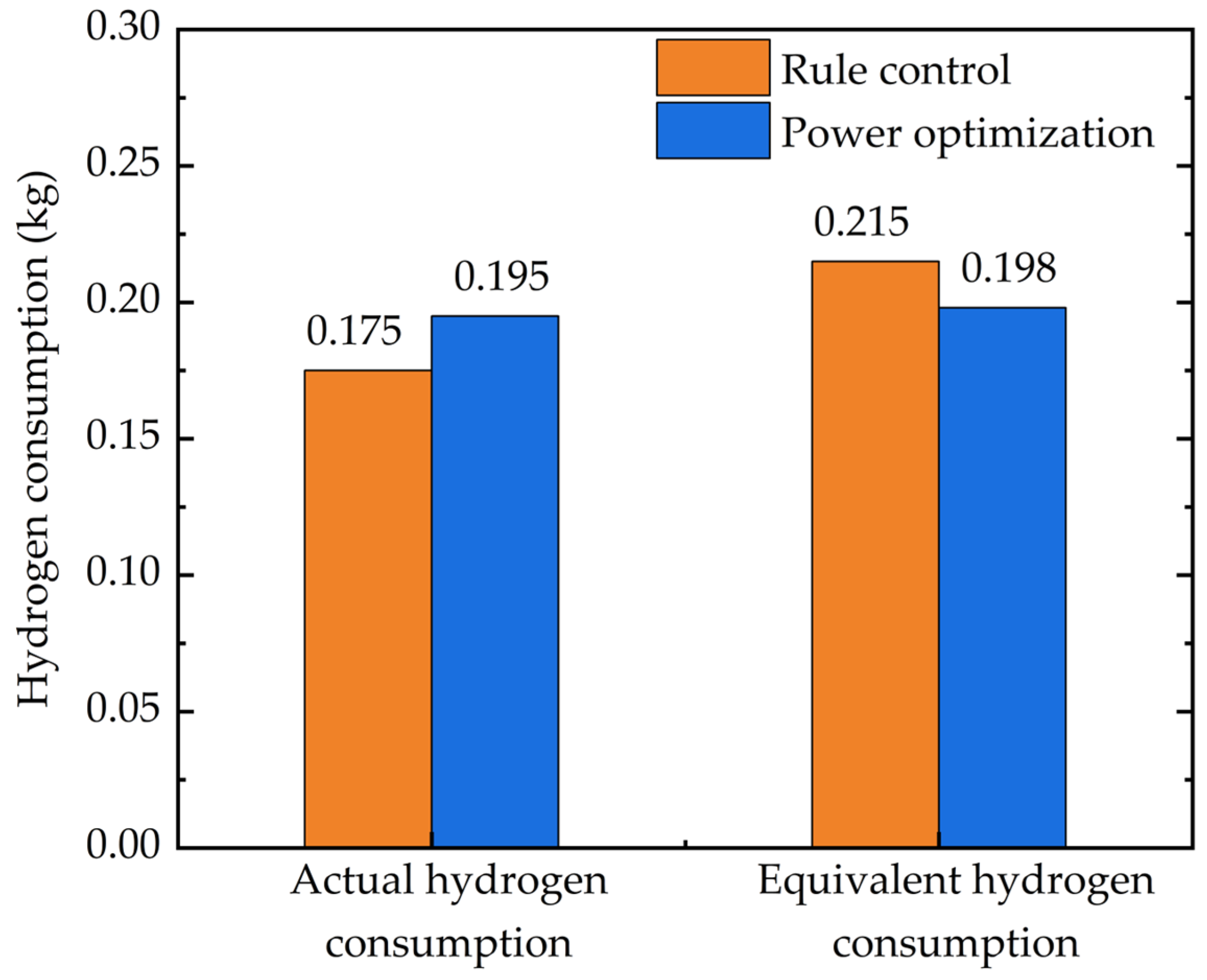
As shown in Figure 12, under the rule-based control strategy, the actual hydrogen consumption at the end of the operating condition is 1.75 × 10⁻¹ kg, with an equivalent hydrogen consumption of 2.15 × 10⁻¹ kg. However, when the tractor adopts the instantaneous optimized power allocation method based on load deceleration, the actual hydrogen consumption at the end of the operating condition is 1.95 × 10⁻¹ kg, and the equivalent hydrogen consumption decreases to 1.98 × 10⁻¹ kg, which is 7.79% lower compared to the rule-based control strategy. The increase in the actual hydrogen consumption and the decrease in the equivalent hydrogen consumption suggest that after optimization, the system more efficiently and stably outputs power from the fuel cell, while less frequently drawing power from the battery. This benefits in maintaining the battery’s state of operation within an ideal range, thus helping to extend the service life of the power battery.
As shown in Figure 12, the rule-based control strategy results in an equivalent hydrogen consumption of 2.15 × 10⁻¹ kg at the end of the operating condition. However, when the tractor uses the instantaneously optimized power allocation method based on load demand, the equivalent hydrogen consumption at the end of the operating condition is reduced to 1.98 × 10⁻¹ kg, which is 7.79% lower than that of the rule-based control strategy.
In conclusion, starting from the load demand, the simulation results analysis of tractor plowing operation can verify that compared to rule-based control strategies, the instantaneously optimized power allocation method based on load demand ensures the FC operates in the high-efficiency range and controls the power battery SOC within a reasonable range. This reduces the equivalent hydrogen consumption of the tractor and improves the overall efficiency of the machine.
6. Conclusions
To address the power allocation challenge of the energy system of a hydrogen FC electric tractor under time-varying operating conditions, this paper takes a hydrogen FC wheel-side drive electric tractor as the research object and proposes an instantaneously optimized power allocation method based on load demand, which effectively improves the energy utilization efficiency.
By simulating and comparing with a rule-based control strategy [22], this paper ultimately proves the strategy proposed herein: effectively improves the output efficiency of the fuel cell system, reduces the fluctuation of the system’s output, enhances the overall performance and stability of the fuel cell system. This simultaneously causes the energy system to rely more on the efficient and stable output of the fuel cell while utilizing the power battery less, which is beneficial for maintaining the power battery’s SOC within an ideal range and for extending the lifespan of the power battery.
There are many factors that affect the performance of hydrogen FCs, which are an important source of energy for the entire machine. The future research goals will focus on the following issues: the threshold power value at which the FC begins to intervene and the minimum operating power set to prevent frequent start-stop of the FC; these values can be further optimized. Furthermore, the strategies in this paper did not take into account the impact of motor efficiency on the overall energy utilization of the system. In the future, further optimization can be conducted on transmission system parameters such as gear ratios of the reducers to improve motor efficiency, thereby enhancing the overall energy utilization efficiency of the system.
Author Contributions
Conceptualization, J.Z. (Jingyun Zhang) and B.W.; methodology, L.X.; software, B.W; validation, J.Z. (Jingyun Zhang), B.W. and L.X.; formal analysis, B.W.; investigation, J.Z. (Junjiang Zhang); resources, L.X.; data curation, K.Z.; writing—original draft preparation, J.Z. (Jingyun Zhang); writing—review and editing, J.Z. (Junjiang Zhang); visualization, K.Z.; supervision, J.Z. (Jingyun Zhang); project administration, L.X.; funding acquisition, K.Z. All authors have read and agreed to the published version of the manuscript.
Funding
This research was funded by the National Key R&D Program of China [2022YFD2001203, 2022YFD2001201B], Henan University of Science and Technology Innovation Team Support Program [24IRTSTHN029], Zhongyuan Science and Technology Innovation Leading Talent Support Program Project [244200510043].
Data Availability Statement
The original contributions presented in the study are included in the article, further inquiries can be directed to the corresponding author.
Conflicts of Interest
Kai Zhang is an employee of YTO Group Corporation, Luoyang 471004, China. The paper reflects the views of the scientists, and not the company.
Nomenclature
| B | Stiffness coefficient. |
| C | Curve shape coefficient. |
| CAN | Controller Area Network. It is a serial communication protocol used for communication between electronic control units in the automotive and industrial fields. |
| Cfc | Hydrogen consumption of the fuel cell system (kg/s). |
| Cbat | Equivalent hydrogen consumption of the power battery (kg/s). |
| D | Peak adhesion coefficient. |
| DC/AC | Direct Current-Alternating Current converter. It is a device that transforms a direct current power source (typically the input power) into another voltage, current, or power level of alternating current. |
| DC/DC | Direct Current-Direct Current converter. It is a device that transforms a direct current power source (typically the input power) into another voltage, current, or power level of direct current. |
| E | Curve curvature coefficient. |
| EH2,low | Low calorific value of hydrogen (1.2 × 10⁸ J/kg). |
| FC | Fuel cell. |
| Ft | Total driving force (N). |
| Ff | Rolling resistance (N). |
| FTN | Rated traction resistance (N). |
| FTa | Ploughing resistance (N). |
| Fx | Longitudinal force of the tyre (N). |
| i | Speed ratio of the wheel-side reducer. |
| Ibat | Battery current (A). |
| MAP | A graph that describes the performance characteristics of an electric motor. It is usually used to express the relationship between the speed, torque and efficiency of the motor under certain conditions. |
| nq | Required speed of the drive wheels (rpm). |
| nreqm | Required speed of the motor (rpm). |
| PEMFC | Proton Exchange Membrane Fuel Cell. It is a type of fuel cell that uses a proton exchange membrane as the electrolyte. |
| Pbat | Battery power (kw). |
| Pfc | Fuel cell system power (kw). |
| Preqbat | Power battery required power (kw). |
| Preqfc | Fuel cell required power (kw). |
| Preqm | Required driving power of the motor (kw). |
| Qbat | Battery rated capacity (A·h). |
| r | Driving wheel radius (m). |
| Rint | Battery internal resistance (Ω). |
| SV | Vertical drift of the curve. |
| SH | Horizontal drift of the curve. |
| SOC | State of charge. |
| SOCH | Given maximum limit of SOC. |
| SOCL | Given minimum limit of SOC. |
| Tm | Motor torque (N·m). |
| Tq | Torque required for the drive wheels (N·m). |
| Treqm | Required torque of the motor (N·m). |
| v | Tractor velocity (m/s). |
| Voc | Battery open circuit voltage (V). |
| Vfc | Fuel cell output voltage (V). |
| X | Tyre slip rate. |
| Y(x) | Longitudinal force of the tyre (N). |
| α | Linear compensation coefficient. |
| β | Adjustment coefficient. |
| γj | Fitting parameters, j = 1–9. |
| ηdis | Instantaneous discharge efficiency of power battery (%). |
| ηchg | Instantaneous charging efficiency of power battery (%). |
| Average discharge efficiency of power battery (%). | |
| Average charging efficiency of power battery (%). | |
| ηfc | Fuel cell system efficiency (%). |
| ηm | Motor efficiency (%). |
| ξj | Fitting parameters, j = 1, 2, 3, 4. |
References
- Group, C.W. World Energy Outlook 2022. Chem. Wkly. 2022, 68, 165–170. [Google Scholar]
- Technical Committee 4.4 Tunnels. Impact of New Propulsion Technologies on Road Tunnel Operations and Safety—A PIARC Technical Report; The World Road Association: Paris, France, 2023; p. 18. [Google Scholar]
- National Development and Reform Commission. The National Development and Reform Commission issued the “Medium and Long-term Plan for the Development of Hydrogen Energy Industry (2021–2035)”. Rare Earth Inf. 2022, 4, 26–32. [Google Scholar]
- Sulaiman, N.; Hannan, M.; Mohamed, A.; Majlan, E.; Daud, W.W. A review on energy management system for fuel cell hybrid electric vehicle: Issues and challenges. Renew. Sustain. Energy Rev. 2015, 52, 802–814. [Google Scholar] [CrossRef]
- Hassan, F. Novel fuel cell/battery/supercapacitor hybrid power source for fuel cell hybrid electric vehicles. Energy 2018, 143, 467–477. [Google Scholar]
- Zhao, S.; Wang, B.; Xie, Y.H.; Han, M.; Jia, J.B. Linear Temperature Sweep Experimental Study on Proton Exchange Membrane Fuel Cell Without External Humidification. Proc. CSEE 2014, 34, 4528–4533. [Google Scholar]
- Li, Q.; Chen, W.R.; Liu, S.K.; Cheng, Z.L.; Liu, X.Q. Application of Multivariable H∞ Suboptimal Control for Proton Exchange Membrane Fuel Cell Pressure Control System. Proc. CSEE 2010, 30, 123–128. [Google Scholar]
- Zhang, H.; Li, Q.; Wang, H.; Li, Q.; Qin, G.; Wu, Q. A review of energy management optimization based on the equivalent consumption minimization strategy for fuel cell hybrid power systems. Fuel Cells 2022, 22, 116–130. [Google Scholar] [CrossRef]
- Peng, J.K.; He, H.W.; Xiong, R. Rule based energy management strategy for a series–parallel plug-in hybrid electric bus optimized by dynamic programming. Appl. Energy 2016, 185, 1633–1643. [Google Scholar] [CrossRef]
- Lü, X.; Wu, Y.; Lian, J.; Zhang, Y.; Chen, C.; Wang, P.; Meng, L. Energy management of hybrid electric vehicles: A review of energy optimization of fuel cell hybrid power system based on genetic algorithm. Energy Convers. Manag. 2020, 205, 112474. [Google Scholar] [CrossRef]
- Fernandez, A.M.; Kandidayeni, M.; Boulon, L.; Chaoui, H. An Adaptive State Machine Based Energy Management Strategy for a Multi-Stack Fuel Cell Hybrid Electric Vehicle. IEEE Trans. Veh. Technol. 2019, 69, 220–234. [Google Scholar] [CrossRef]
- Shen, Y.; Cui, P.; Wang, X.; Han, X.; Wang, Y.-X. Variable structure battery-based fuel cell hybrid power system and its incremental fuzzy logic energy management strategy. Int. J. Hydrogen Energy 2020, 45, 12130–12142. [Google Scholar] [CrossRef]
- Wen, P.M.; Song, K.; Zhang, T. Energy management strategy of thermostat for fuel cell vehicles based on Pontriagin minimum principle. Mechatronics 2017, 23, 7–12. [Google Scholar] [CrossRef]
- Wang, Y.J.; Sun, Z.D.; Chen, Z.H. Energy management strategy for battery/supercapacitor/fuel cell hybrid source vehicles based on finite state machine. Appl. Energy 2019, 254, 113707. [Google Scholar] [CrossRef]
- Wang, Z.F.; Xu, S.; Luo, W. Research on energy management strategy of fuel cell vehicle based on dynamic programming. Acta Energiae Solaris Sin. 2023, 44, 550–556. [Google Scholar]
- Song, K.; Zhang, T.; Niu, W.X.; Zhang, T. Error accumulation problem and solution of dynamic programming algorithm for energy management of fuel cell electric vehicles. Automot. Eng. 2017, 39, 249–255. [Google Scholar]
- Zhou, W.; Yang, L.; Cai, Y.; Ying, T. Dynamic programming for new energy vehicles based on their work modes Part II: Fuel cell electric vehicles. J. Power Sources 2018, 407, 92–104. [Google Scholar] [CrossRef]
- Zhou, Y.; Li, H.; Ravey, A.; Péra, M.-C. An integrated predictive energy management for light-duty range-extended plug-in fuel cell electric vehicle. J. Power Sources 2020, 451, 227780. [Google Scholar] [CrossRef]
- Zhou, Y.; Ravey, A.; Péra, M.-C. Multi-mode predictive energy management for fuel cell hybrid electric vehicles using Markov driving pattern recognizer. Appl. Energy 2020, 258, 114057. [Google Scholar] [CrossRef]
- Wang, Z.; Xie, Y.; Zang, P.F.; Wang, Y. Energy management strategy of fuel cell bus based on Pontryagin’s minimum principle. J. Jilin Univ. (Eng. Technol. Ed.) 2020, 50, 36–43. [Google Scholar]
- Nie, Z.; Jia, Y.; Wang, W.; Chen, Z.; Outbib, R. Co-optimization of speed planning and energy management for intelligent fuel cell hybrid vehicle considering complex traffic conditions. Energy 2022, 247, 123476. [Google Scholar] [CrossRef]
- Xu, L.Y.; Liu, E.Z.; Liu, M.N.; Zhao, X.P.; Wang, T. Energy Management Strategy for Hybrid Fuel Cell/Battery Electric Tractor. J. Henan Univ. Sci. Technol. (Nat. Sci.) 2019, 40, 80–86. [Google Scholar] [CrossRef]
- Gao, X.L.; Shi, S.B. Tractor vehicle dynamics. In Tractor Automobile Engineering Volume 2: Vehicle Chassis and Theory; China Agriculture Press: Beijing, China, 2009; pp. 178–206. [Google Scholar]
- Liu, M.N. Study on Design Theory and Control Strategy of Electric Tractor. Ph.D. Thesis, Vehicle Engineering, Xi’an University of Technology, Xi’an, China, 2020. [Google Scholar]
- Wang, Z.Z.; Zhou, J.; Wang, X. Research on Energy Management Model of Extended Range Electric Tractor Rotary Tiller Unit. Trans. Chin. Soc. Agric. Mach. 2023, 54, 428–438. [Google Scholar] [CrossRef]
- Xu, L.F.; Lu, L.G.; Li, J.Q.; Ouyang, M.G. Modeling and Simulation of a Hybrid Fuel Cell System and Energy Management Strategy. J. Mech. Eng. 2009, 45, 141–147. [Google Scholar] [CrossRef]
- Yang, Y.; Hu, X.; Pei, H.; Peng, Z. Comparison of power-split and parallel hybrid powertrain architectures with a single electric machine: Dynamic programming approach. Appl. Energy 2016, 168, 683–690. [Google Scholar] [CrossRef]
- van Harselaar, W.; Hofman, T.; Brouwer, M. Automated Dynamic Modeling of Arbitrary Hybrid and Electric Drivetrain Topologies. IEEE Trans. Veh. Technol. 2018, 67, 6921–6934. [Google Scholar] [CrossRef]
- Zhang, J.J. Research on Control Strategy of Four-Wheel Drive Pure Electric Vehicles Taking into Account Regenerative Braking and Ride Comfort. Ph.D. Thesis, Vehicle Engineering, Chongqing University, Chongqing, China, 2021. [Google Scholar]
- Wang, T.; Li, Q.; Han, Y.; Hong, Z.; Liu, T.; Chen, W. Fuel Cell Hybrid Power Generation System Equivalent Hydrogen Consumption Instantaneous Optimization Energy Management Method. Proc. CSEE 2018, 38, 4173–4182+4323. [Google Scholar]
- Ehsani, M. Modern Electric, Fuel cell. In Hybrid Electric, and Fuel Cell Vehicles Fundamentals, Theory and Design, 2nd ed.; China Machine Press: Beijing, China, 2010; pp. 363–385. [Google Scholar]
- Pacejka, H.B.; Bakker, E. The magic formula tyre model. Veh. Syst. Dyn. 1992, 21, 1–18. [Google Scholar] [CrossRef]
- Gan, X.Q.; Zhang, H.B.; Zhang, N. An Equivalent Fuel Consumption Minimization Strategy for Fuel Cell Vehicles Based on Variable Equivalent Coefficient. J. Tongji Univ. (Nat. Sci.) 2021, 49, 224–230. [Google Scholar] [CrossRef]
Figure 1.
Topology of the hydrogen fuel cell wheel-driven electric tractor.
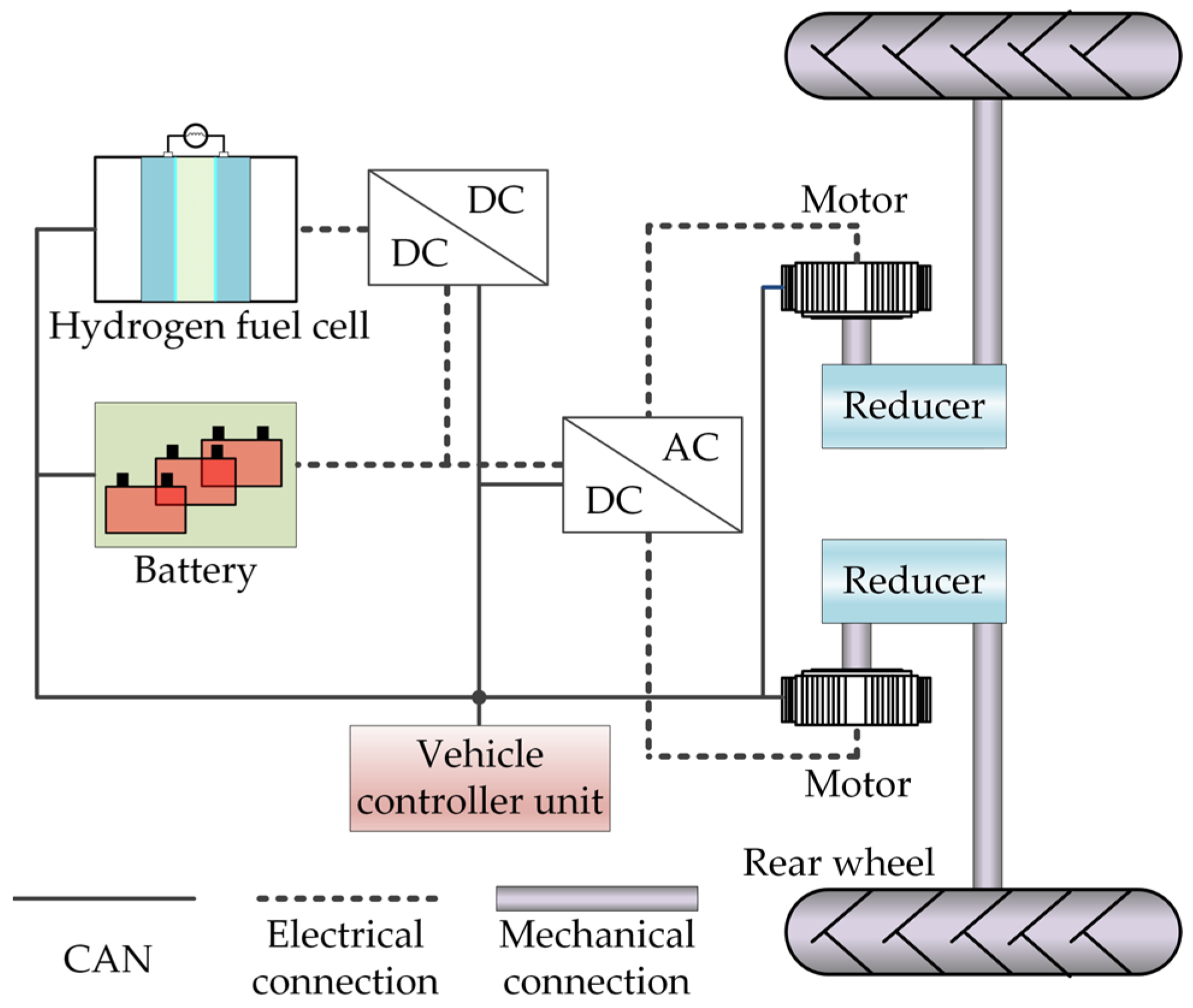
Figure 2.
MAP diagram of a motor model.
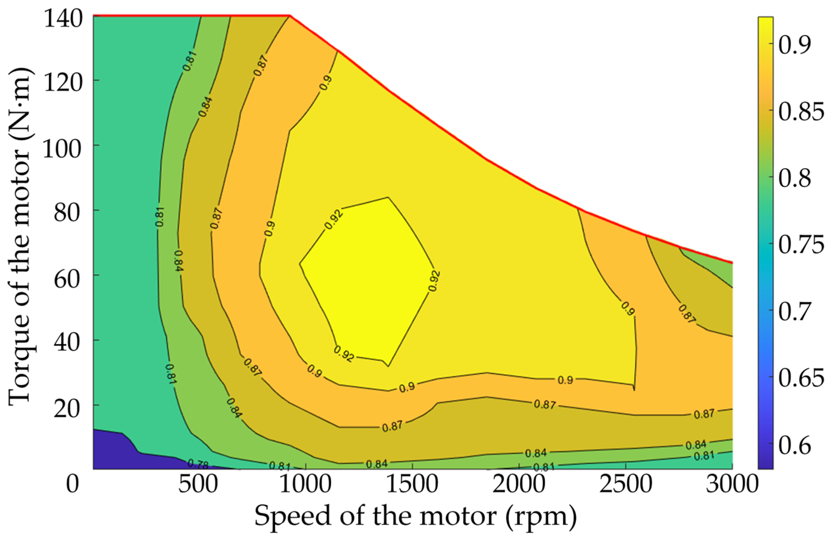
Figure 3.
Operational characteristics of the hydrogen FC system.

Figure 4.
Schematic diagram of the whole-machine simulation mode.

Figure 5.
Scheme process of energy system power optimization method.

Figure 6.
Ploughing velocity and resistance over time.
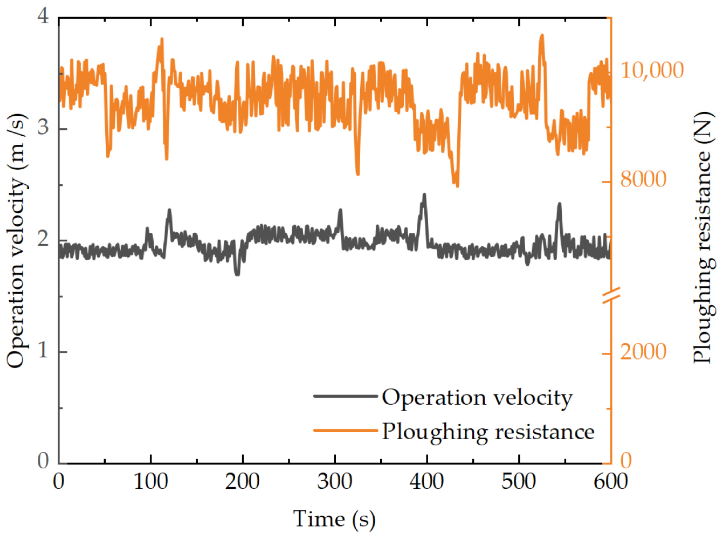
Figure 7.
Hydrogen fuel cell operating point.
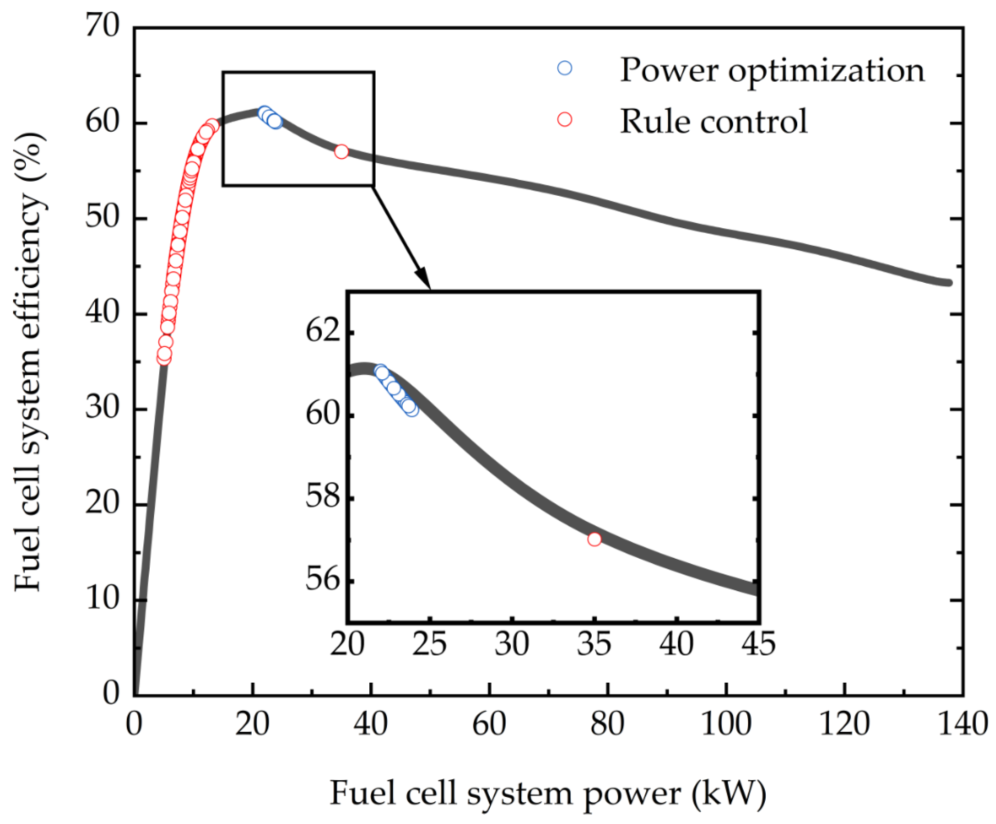
Figure 8.
Hydrogen fuel cell system instantaneous efficiency over time.
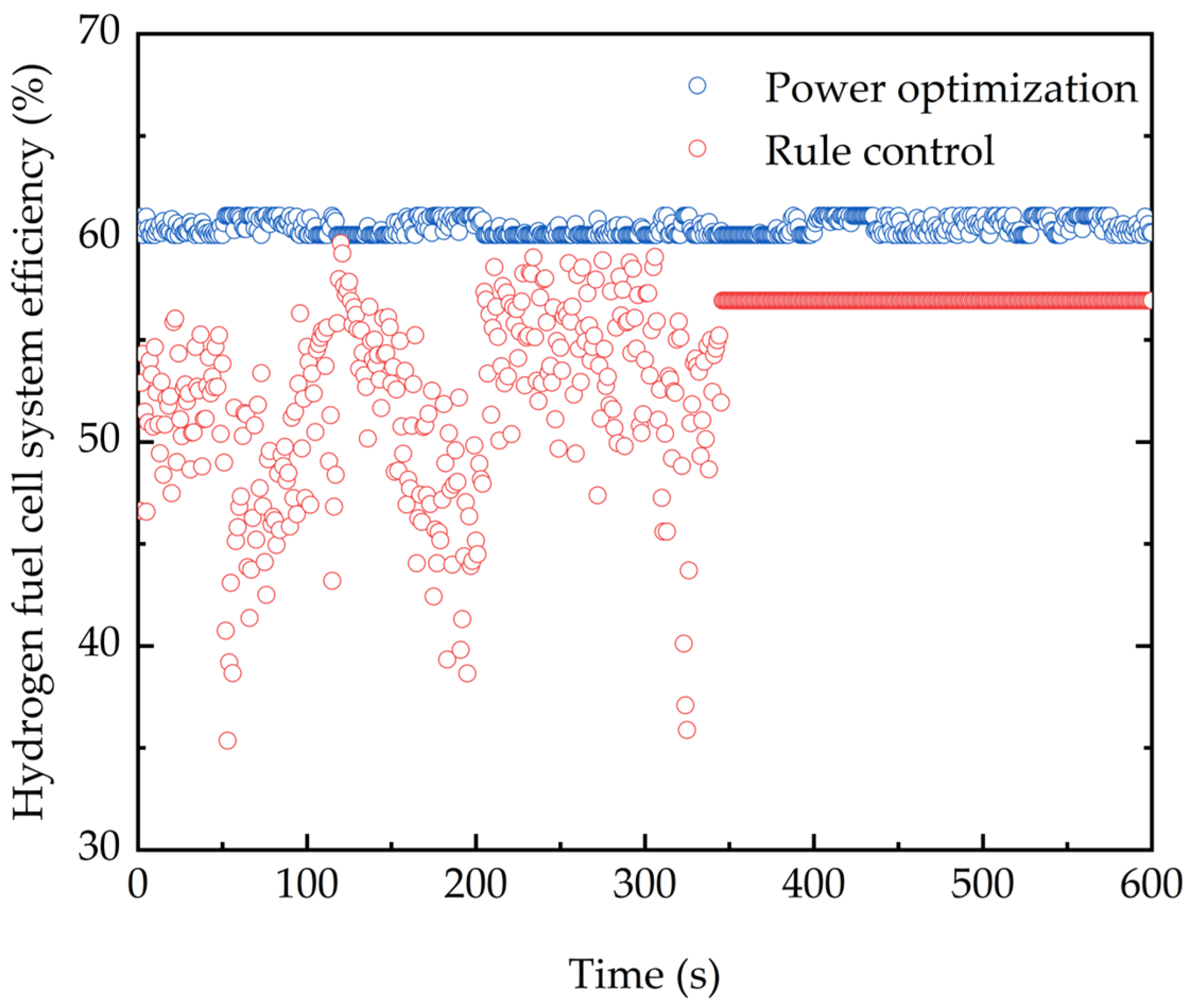
Figure 9.
The output power of the fuel cell and power battery over time.
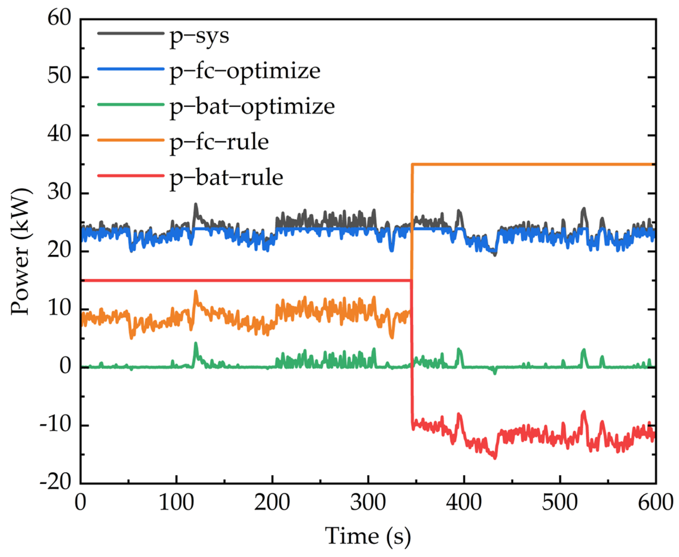
Figure 10.
The power battery SOC over time.

Figure 11.
Variation of equivalent hydrogen consumption over time.
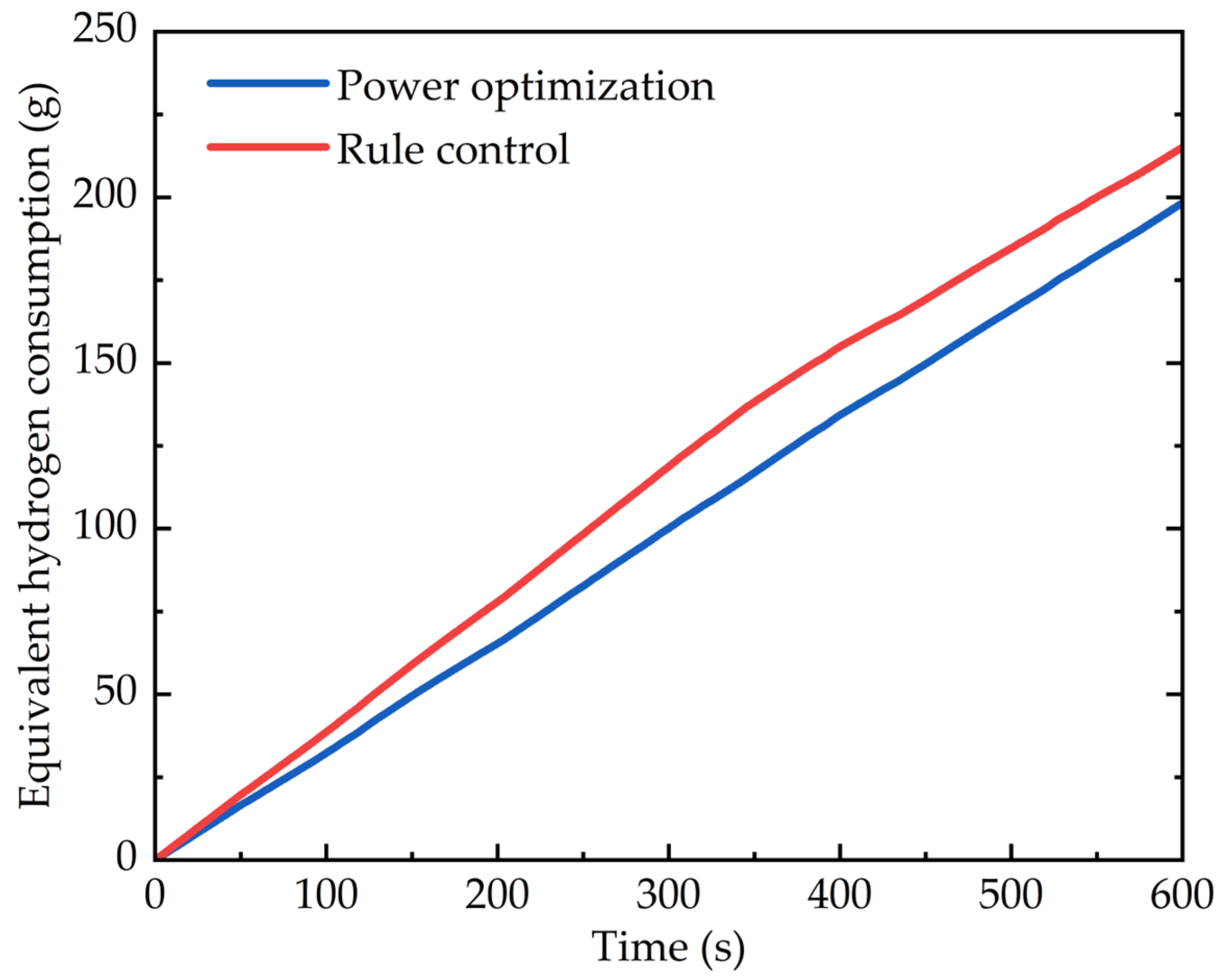
Figure 12.
Hydrogen consumption under two control strategies.

Table 1.
Topology of a diesel-electric parallel hybrid tractor.
| Project | Parameters/Units | Value |
|---|---|---|
| Vehicle parameters | Tractor mass (kg) | 2500 |
| Driving wheel rolling radius (m) | 0.63 | |
| Rolling resistance coefficient | 0.07 | |
| Reducer speed ratio | 17 | |
| Motor | Rated speed (rpm) | 1500 |
| Rated torque (N·m) | 140 | |
| Rated power (kW) | 22 | |
| Power System | Energy capacity (kW·h) | 41 |
| Battery voltage (V) | 380 | |
| Battery capacity (A·h) | 108 |
Disclaimer/Publisher’s Note: The statements, opinions and data contained in all publications are solely those of the individual author(s) and contributor(s) and not of MDPI and/or the editor(s). MDPI and/or the editor(s) disclaim responsibility for any injury to people or property resulting from any ideas, methods, instructions or products referred to in the content. |
© 2024 by the authors. Licensee MDPI, Basel, Switzerland. This article is an open access article distributed under the terms and conditions of the Creative Commons Attribution (CC BY) license (https://creativecommons.org/licenses/by/4.0/).
Share and Cite
MDPI and ACS Style
Zhang, J.; Wang, B.; Zhang, J.; Xu, L.; Zhang, K. Research on Power Optimization for Energy System of Hydrogen Fuel Cell Wheel-Driven Electric Tractor. World Electr. Veh. J. 2024, 15, 188. https://doi.org/10.3390/wevj15050188
AMA Style
Zhang J, Wang B, Zhang J, Xu L, Zhang K. Research on Power Optimization for Energy System of Hydrogen Fuel Cell Wheel-Driven Electric Tractor. World Electric Vehicle Journal. 2024; 15(5):188. https://doi.org/10.3390/wevj15050188
Chicago/Turabian StyleZhang, Jingyun, Buyuan Wang, Junjiang Zhang, Liyou Xu, and Kai Zhang. 2024. "Research on Power Optimization for Energy System of Hydrogen Fuel Cell Wheel-Driven Electric Tractor" World Electric Vehicle Journal 15, no. 5: 188. https://doi.org/10.3390/wevj15050188