1. Introduction
In recent years, train passengers have been transferring increasing amounts of data via their mobile devices. In addition, online applications targeted at mobile users are also proliferating. Consequently, a means of providing broadband mobile communication that satisfies the communication demands of passengers in high-speed trains is essential. To address this need, we propose a mobile relay node (MRN)-based network architecture for communications on high-speed trains. Using this network architecture, Long-Term Evolution (LTE) can achieve high data rates to support multimedia applications, such as Voice over IP (VoIP), video gaming and video streaming, over wireless networks for access anytime and anywhere on mobile broadband networks. The data communication system used by the railway network has been described as facilitating next-generation railway networks based on LTE technology [
1]. An LTE network comprises many interconnected Evolved Node Bs (eNBs), which are components of the Evolved Universal Terrestrial Radio Access Network (E-UTRAN). eNBs are connected to the mobility management entity (MME), serving gateway (S-GW) and packet data network gateway (P-GW) in the Evolved Packet Core (EPC) network to support various kinds of services, such as signaling, handover (HO) and security [
2].
Long-Term Evolution Advanced (LTE-A) is a developing standard that can satisfy International Mobile Telecommunications (IMT) advanced requirements for 4G mobile networks. Currently, the LTE-A standard working group is considering adoption of mobile relays to support data services in high-speed rail systems [
3]. MRN is a feature enhancement for next-generation networks. In a system that utilizes MRN, the user equipment (UE) and the vehicle’s passengers do not use the HO; instead, only the MRN executes the HO, using the external antenna of the vehicle [
4,
5]. However, in LTE-A Release 12, the mobile relay HO reuses the existing UE HO procedure [
5]. The HO and MME of the LTE network are unsuitable for high-speed vehicles. Moreover, in vehicle cabins, the effects of high penetration loss, Doppler frequency shift, reduced HO success rate and increased power consumption affect passenger devices [
5]. Furthermore, because of rapid movement in overlap areas, increased radio link failures (RLFs) and vehicle service interruptions occur.
Many studies on the 3rd Generation Partnership Project (3GPP) LTE system have focused on self-organizing networks (SONs) to minimize capital expenditure (CAPEX) and operating expenditure (OPEX) and to maximize operator revenue through automatic network management [
6]. This self-configuration and self-optimization comprise dynamic networks. Note that the HO procedure in the network-controlled HO of the 3GPP LTE system is closely connected to the self-optimization that collects measurement information from the UE and eNB; it then automatically tunes the configuration data to optimize the network. The HO parameter optimization is part of self-optimization. The SON automatically optimizes HO parameters to increase HO performance. Thus, self-optimization schemes can dynamically choose HO parameters in wireless networks [
7,
8].
To reduce the number of RLFs and connection interruptions that occur during HO procedures in broadband mobile communication systems with MRNs, we dynamically tune the HO hysteresis and cell individual offset (CIO) based on the velocity of the train and the HO performance indicator (HPI) of the cell.
In [
9], two HO schemes that adjust HO parameters to improve network performance are proposed. The first scheme is a rapid HO algorithm based on UE velocity. In this scheme, the HO hysteresis (HH) and time-to-trigger (TTT) are adjusted to ensure the HO success rate and communication quality at velocities between 0 km/h and 350 km/h. The second scheme focuses on TTT optimization. In [
10], an LTE-based cell array solution that supports high throughput and continuous multimedia service is proposed. This scheme prepares a cell array based on the mobility direction and speed of the train. In [
11], an HO scheme that utilizes coordinated multi-points for moving vehicular femtocell networks is presented. In this scheme, several external antennas are installed on the train. When the train reaches an overlap area, all external antennas send measurement reports to the serving cell. Firstly, an external antenna with weak received signal strength (RSS) from the serving cell begins the HO. Then, other external antennas execute the HO. A similar scheme is presented in [
12]. This scheme supports bicasting during the HO procedure. In addition, HO schemes with bicasting solutions have been proposed to increase system throughput by other researchers [
13,
14].
The main focus of this paper is on the HO decision triggering in the high-speed environment. If the serving cell does not begin the MRN’s HO procedure at the correct time, the MRN must leave the serving cell coverage area before the HO procedure is completed. Otherwise, the MRN incurs RLFs.
When an RLF occurs during the HO procedure, the HO delay becomes longer than that of a normal HO without RLF; in addition, the number of connection interruptions increases. Therefore, we optimize the HO parameters that begin the HO procedure at the correct time and reduce RLFs. Further, we propose an HO scheme in which dual MRNs are installed on the train. Only one of the two MRNs produces a measurement report, with its HO procedure triggered by the serving cell. The other MRN executes an HO that emulates the already triggered HO.
3. Discussion
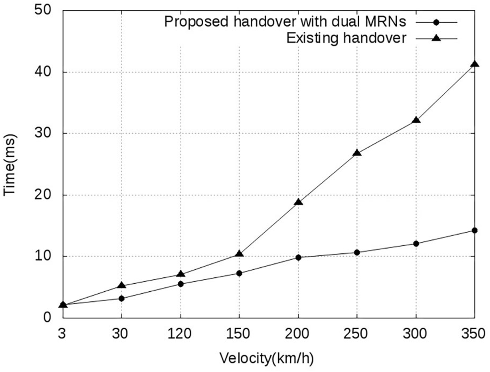
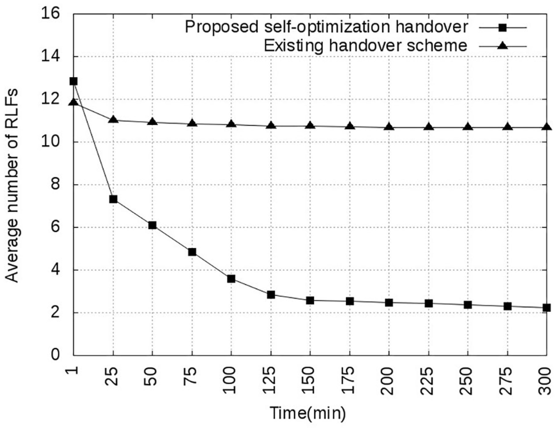
The above section results show that, overall, the proposed self-optimizing HO parameter scheme with dual MRNs is superior to the conventional static scheme with fixed parameter values. This is because a fixed parameter setting is adequate for general cases and UEs, but in a high-speed environment, a more flexible scheme is necessary. The proposed self-optimization scheme automatically tunes parameters based on performance and velocity; therefore, the HH and CIO can be set to more appropriate values that are in line with changes in data communication.
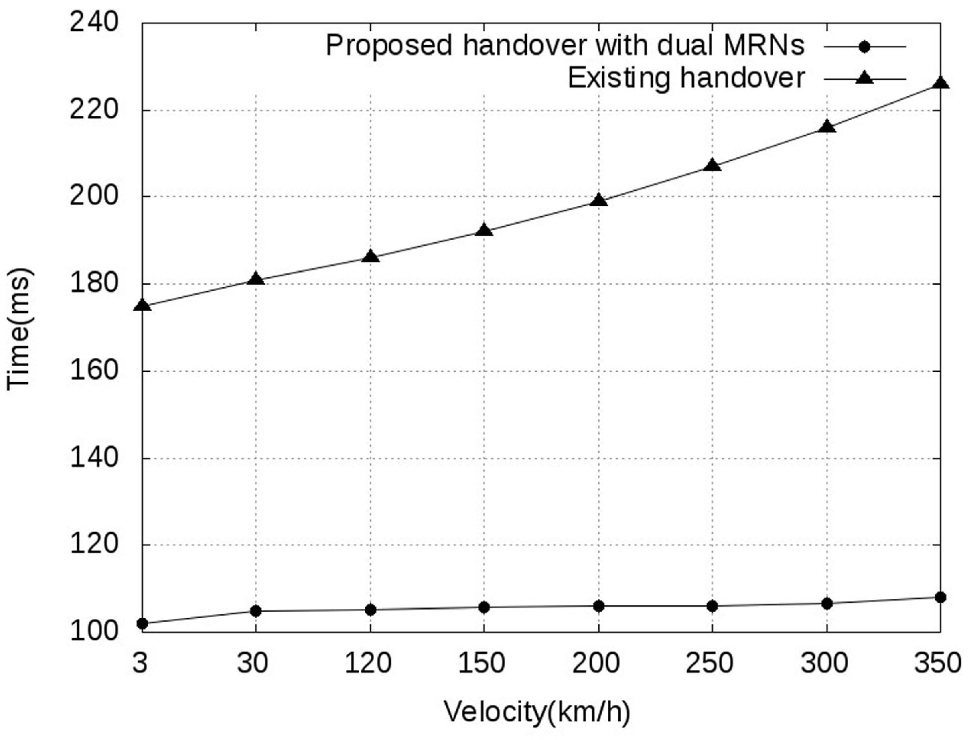
In the implementation of our dual MRNs, the communication interruption time is reduced. This result can be explained by the following processes: (i) the passengers of the train are served by the sMRN during the HO procedure of the main mobile relay node (mMRN); (ii) if the HO procedure of the mMRN has failed, only mMRN starts the new HO procedure; and (iii) the dual MRNs execute the HO procedures by the powerful outside antennas of the train. In this scenario, outside antennas can use the MIMO that can provide the QoS of the backhaul link to the DeNBs.
4. Backgrounds and Methods
In this section, we first give an overview of the HO procedure and the parameters involved. Moreover, we look at RLFs, HPI and related work on self-optimization HO parameters. Then, we present our proposed HO parameter optimization and dual MRNs network model. Two main concepts are presented: (i) we present our optimization scheme for the HH and CIO parameters; the proposed scheme selects a suitable HH and changes the CIO of each cell to facilitate the HO decision step of the HO process when the train is moving at a high speed; and (ii) we outline our proposed dual MRNs network model and its HO procedure. The proposed model provides seamless mobility and uses the co-operating dual MRNs to reduce connection interruptions.
4.1. Backgrounds
4.1.1. LTE Handover and Parameters
The HO is a major task that supports continuous transmission for a UE moving across different radio coverage areas. In the standard LTE system, HO is based on the network-controlled hard HO (NCHH) [
4]. NCHH is a “break before make” method; that is, the radio link between the UE and serving cell is disconnected before a new radio link is established between the UE and the target cell. A mobile relay HO procedure, such as the typical HO procedure, includes three phases: preparation, execution and completion [
5].
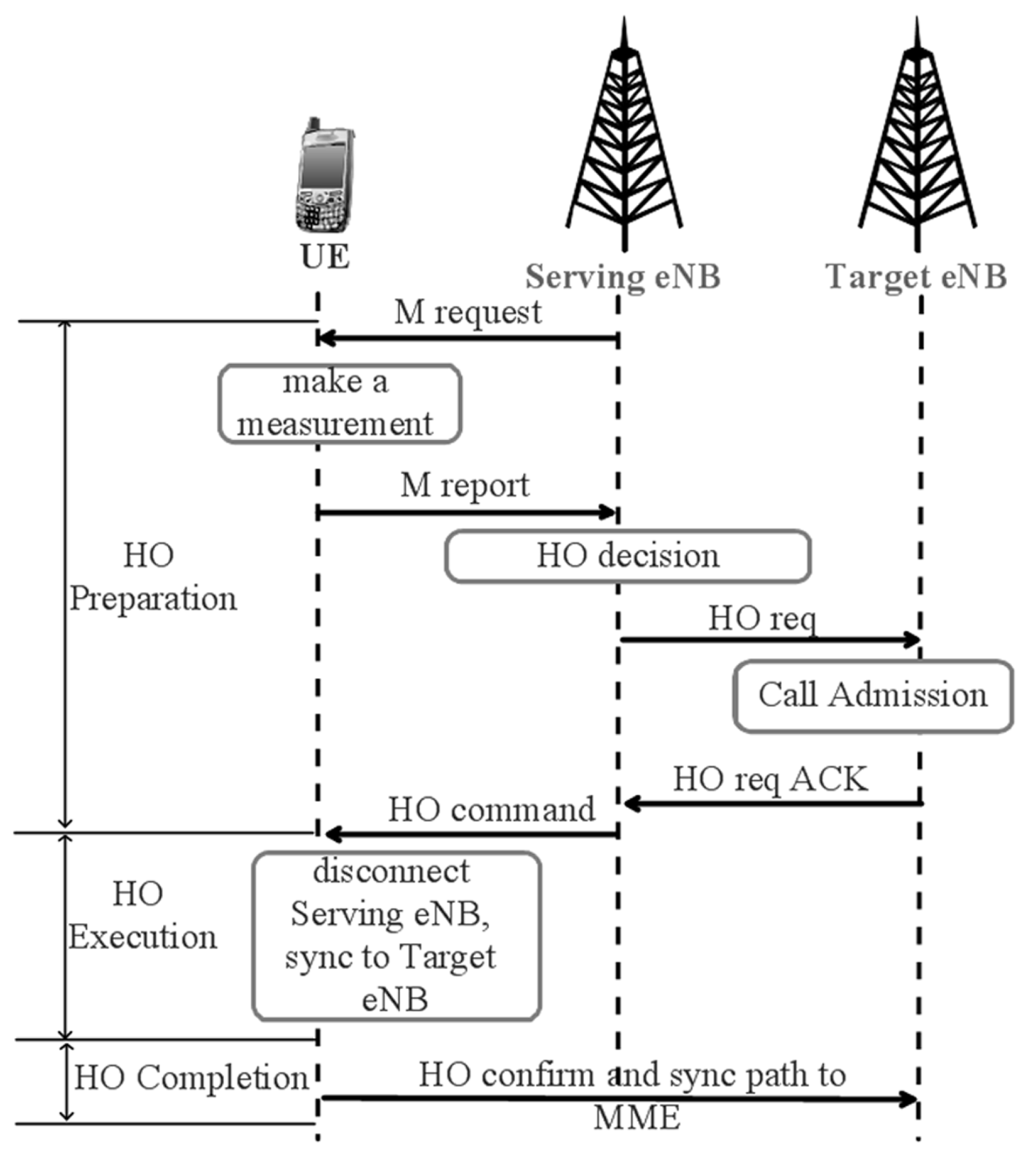
Figure 6 depicts the existing HO procedures of the LTE. In this procedure, the serving eNB sends a measurement control command (M request) to a UE. On receiving the measurement control command, the UE starts the measurement procedure and consequently sends a measurement report (M report) to the serving eNB. The serving eNB then makes the HO decision and selects the target eNB based on the measurement report from the UE. The preparation phase is thus completed. If the HO is necessary, the serving eNB sends the HO request (HO req) to the target eNB. The target eNB accepts and prepares the HO of the UE and replies with the HO request ACK (HO req ACK) to the serving eNB. Then, the serving eNB sends a HO command (HO command) to the UE. Upon receiving the HO complete message (HO confirm), the UE disconnects from the serving eNB and requests a connection with the target eNB. If the HO is successful, the UE replaces the status of the serving eNB from the target eNB.
Figure 6.
Existing hard HO procedure for user equipment (UE) in LTE.
Figure 6.
Existing hard HO procedure for user equipment (UE) in LTE.
Let us now look at the important HO parameters for our focus “Event A3” based on NCHH. In the HO procedure [
17], the presented HO parameters are HH, TTT, offset and CIO. The CIO is the departing range of the serving cell or the entering range of the target cell if a CIO is stored in that cell. Otherwise, if it is equal to zero, the departing or entering range of the cell is set as the measurement result. Equation (
1) defines the condition for Event A3:
where
and
denote the measured RSS of the target eNB and serving eNB, respectively.
and
are the CIOs of the target eNB and serving eNB, respectively.
denotes hysteresis, and
is the offset.
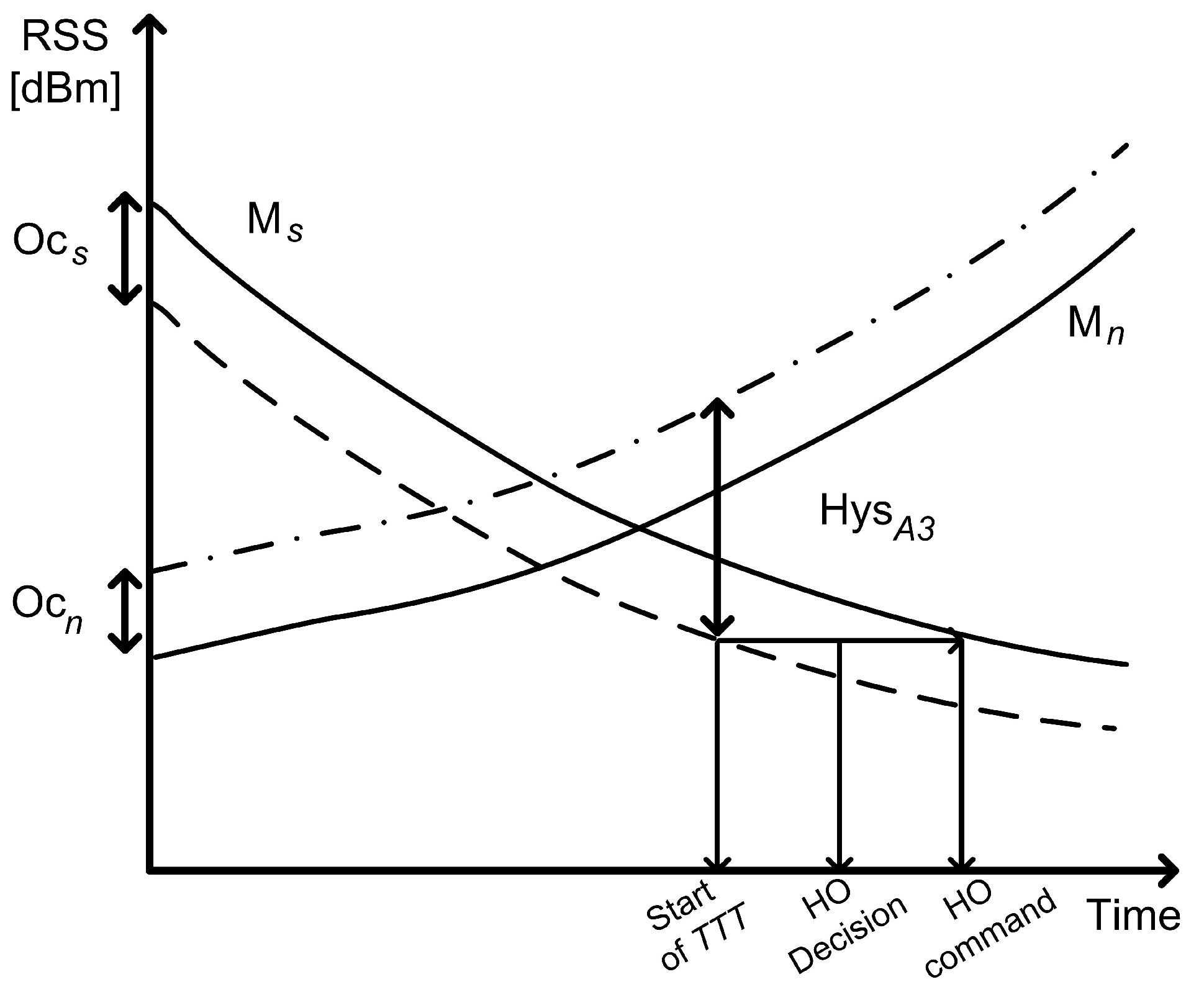
Figure 7 illustrates the entering condition for the target cell based on Event A3 in the LTE network. Hys1 denotes
+
−
. Once the condition for Event A3 is satisfied, the serving cell can begin the TTT. After TTT is finished, if the condition is satisfied, the serving cell initiates the HO procedure using the HO request command (HO preparation phase). The serving cell sends the HO command on receiving “HO req ACK” from the target cell.
Figure 7.
Event A3-based HO parameters in LTE networks.
Figure 7.
Event A3-based HO parameters in LTE networks.
4.1.2. Radio Link Failures
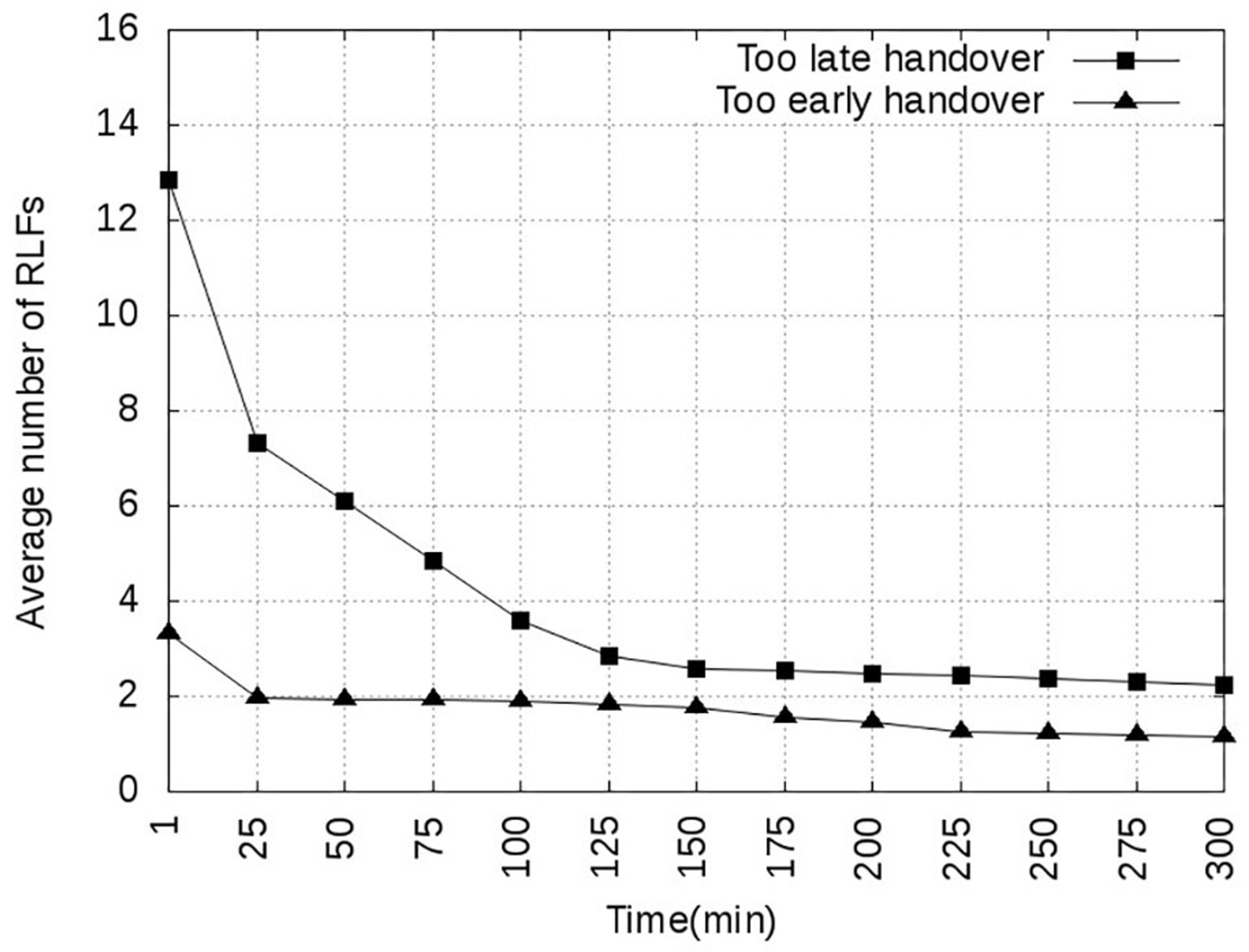
In some cases, the general configuration of the HO parameters is unsuitable. If the serving eNB does not initiate the HO at the correct time, an HO that is too early or too late occurs, which results in an increase in the number of RLFs. Moreover, the radio link must be re-established to the serving eNB, which causes the HO procedure to restart.
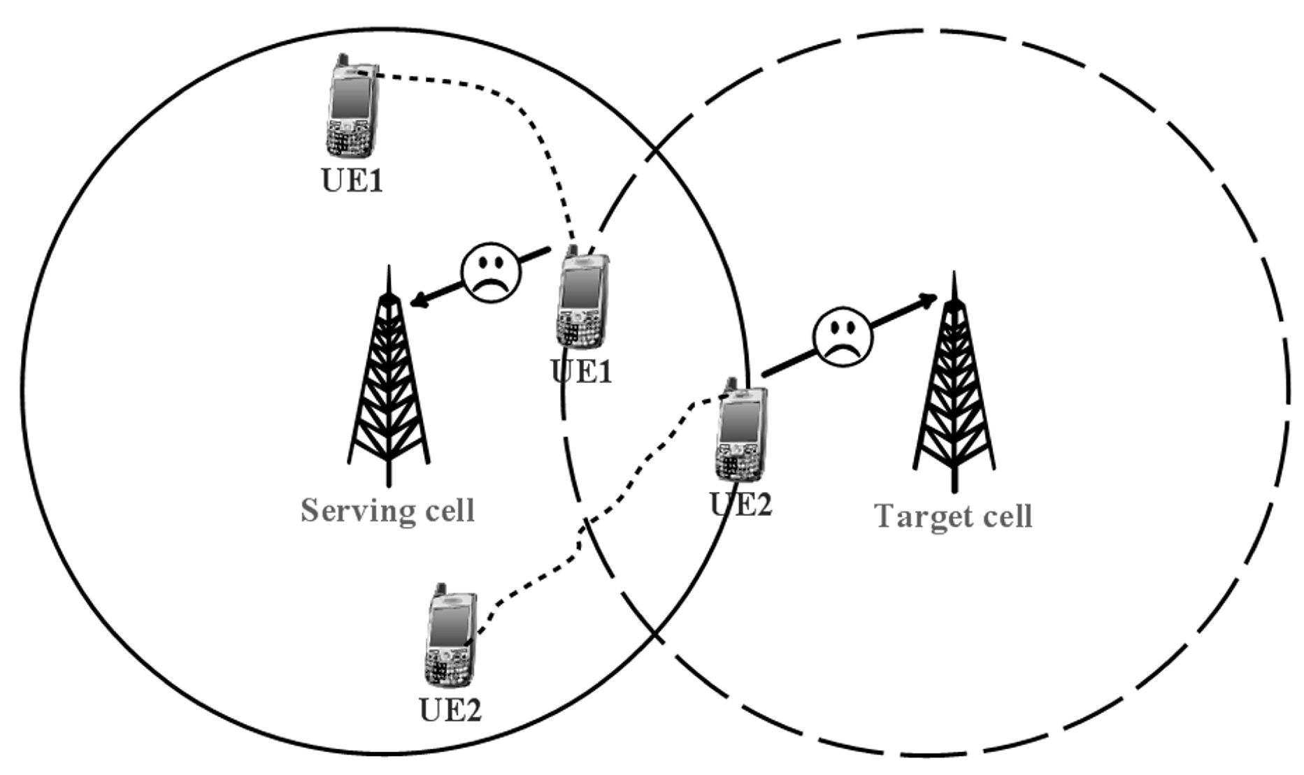
Figure 8 illustrates late and early HOs with two UEs and high-speed movement between cells.
Before the HO procedure finishes, if the signal quality of the serving cell is inadequate for the data communication requirement, a late HO occurs. Otherwise, if the HO procedure has already been completed when the signal quality of the target cell becomes inadequate for the communication requirement, an HO that is too early occurs. In other cases, an increase in the number of RLFs is due to ineffective target cell selection by the HO decision algorithms.
Figure 8.
UE1 started the HO too early. UE2 started the HO too late.
Figure 8.
UE1 started the HO too early. UE2 started the HO too late.
4.1.3. Handover Performance Indicator
HPI serves to monitor the performance of the HO procedures by each cell. The total HPI is a summation of the handover failures (HOF), handover ping-pong (HPP) and RLF indicators (Equation (
2)).
In [
18], the following definitions is defined:
: If the HO procedure fails when the UE connects to the target cell, the UE must re-establish the connection to the serving cell and begins a new HO procedure. If UE moves out of coverage of the serving cell, the re-establishment process also fails. It is added to the RLFs. The failed HPI is the ratio of the number of the HO failures (
) to the total number of the HOs (
).
signifies the total number of the HO attempts.
: The ping-pong HPI is the ratio of the number of ping-pong HOs (
) to the total number of HOs:
is the number of the HO calls that were dropped (by the network) before the HO procedure was finished, if the signal quality was not enough for the data communication requirement, and the UE moves out of coverage of the serving cell. In this scenario, the UE drops the HO and sends a new connection request to the nearest available cell (based on measurement).
is the ratio of
to the number of calls that were accepted in the target cell:
4.1.4. Handover Self-Optimization Related Works
To minimize the oscillations of the HOs by the TTT and HO margin, parameters are optimized in [
19]. Another oscillation-focused scheme is also proposed in [
20]. The proposed scheme adjusts the TTT and HH to minimize the number of RLFs. In [
21], an algorithm that finds the best HH and TTT combination, which serves to improve the HO performance, is presented. In the proposed algorithm, a weighting HPI function that includes the ping-pong HO, HO failures and dropped calls is defined. The HO parameters of individual HPIs are also weighted in order to reduce the number of HOFs, HPPs and RLFs [
18]. In [
22], the focus is on UE speed-based mobility robustness optimization, which involves optimized HH and classified UE speed. Simulation results are presented for cases in which TTT and CIO are constant for all users; however, each cell has its own CIO.
4.2. Handover Parameter Optimization Method
In this section, we describe how the HH and CIO parameters are calculated. The HH, CIO, threshold, offset and TTT parameters are discussed in [
17]. Our self-optimization scheme focuses on the HH and CIO parameters. First, we present the calculation for HH, which is the main parameter associated with the triggering of NCHH (Event A3 condition). For example, in a typical hysteresis adjustment scheme, a large HH value is used for the Event A3 HO. Otherwise, if the difference between the signal quality of the neighboring cells and that of the serving cell is high, and MRN is at the cell boundary of the serving cell, the HO of MRN may begin late, in which case, HH should be decreased. However, if a small HH value were being used up to that point, then the HH value should be increased.
Our proposed velocity-based HH adjustment value is defined in Equation (
7). If the velocity of the vehicle is high, the starting time of the HO procedure may be too late. Therefore, we must reduce the HH of the LTE system. Otherwise, if HH is set too small, the HO procedure decision will be made too early compared with when the default HH of the LTE system is set.
where
denotes the default hysteresis for all UEs,
is the maximum speed of the vehicle and
is the current speed of the vehicle, which includes vehicle context information. The maximum speed of a high-speed train is currently 350 km/h in Japan. According to Equation (
6), if the velocity of the train increases, the HH will decrease. Otherwise, if the velocity of the train decreases, HH will incur minimal changes.
Let us now look at the CIO calculation for the serving DeNB based on HPI. The CIO parameter provides radio resource management for each cell. To monitor the performance of the HO procedures, we compute the HPI as the ratio of the sum of the dropped HOs, HO failures and HOs that are too late to the total number of the HOs. The total number of the HOs is the sum of all of the HOs that are triggered in the target cell. Equation (
7) defines the HPI for our proposed CIO adjustment scheme.
where
,
and
are the number of dropped HOs, failed HOs and late HOs, respectively. The unsuccessful HOs are added to these indicators when the procedure has failed, because of the radio link quality.
If the CIO of the neighboring cells is high, the HO of MRN may begin early. An HO that is too early must be controlled. Equation (
8) shows the calculation carried out for an HPI that is too early.
where
and
are the number of ping-pong HOs and early HOs, respectively.
The proposed scheme controls the HH and CIO parameters for Event A3 NCHH. The proposed algorithm is outlined in Algorithm 1.
| Algorithm 1 Proposed HO parameter optimization algorithm |
Collect of context information
Collect of RLFs, CIO of Neighbor Cells, HOP and HPP
Calculate HH adjustment value
if then
for do
if then
.
end if
end for
end if
if then
for do
if then
.
end if
end for
end if |
If the CIO of the neighboring cells is low, the HO of MRN may start too late. Consequently, the MRNs incur a connection loss if the serving cell cannot provide a consistent and sufficiently high-quality signal for the MRN. Therefore, the proposed scheme increases the CIO of neighboring cells. Otherwise, if the number of RLFs in the neighboring cells is more than the threshold, we increase the number of CIOs in the neighboring cells to reduce the number of RLFs. Finally, the NCHH Event A3 condition changes are summarized in Equation (
9).
where
denotes the measured RSS of the target eNB,
denotes the RSS of the serving eNB,
is the CIO configured by the target DeNB based on HPI and
is the calculated hysteresis based on the vehicle velocity.
4.3. Handover Procedure of the Dual MRNs
In this section, we outline the proposed network model with dual MRNs, illustrated in
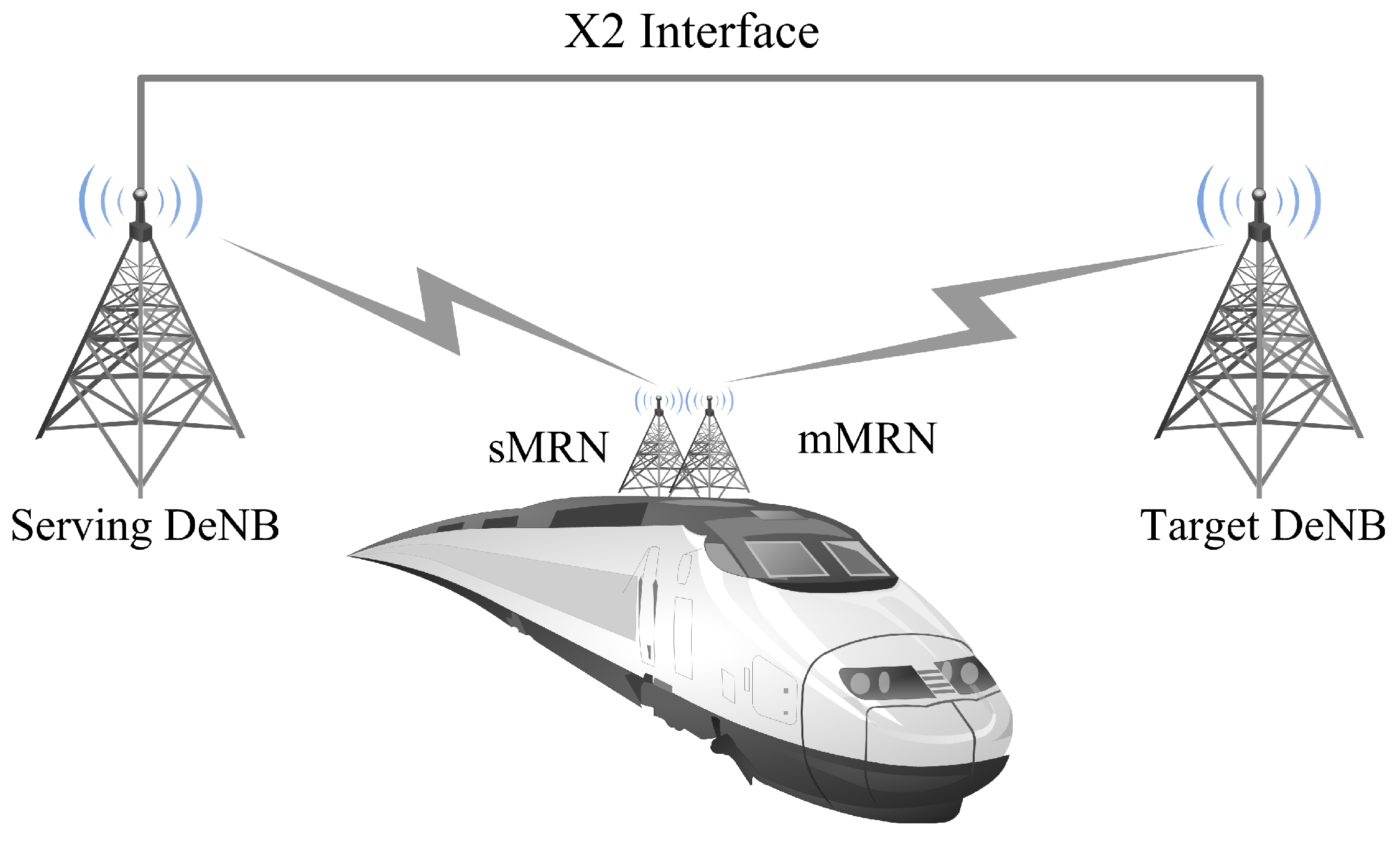
Figure 9. A main MRN (mMRN) and a secondary MRN (sMRN) are located at the front of the vehicle (without distance). The benefit of this model is that mMRN performs the proposed HO scheme and represents it for the sMRN. The dual MRN-based network architecture focuses on broadband wireless communication and is intended for passengers of high-speed vehicles. The passengers connect directly to an access point installed inside the vehicle. This access point connects to the donor eNBs (DeNBs) of the LTE network, which employs dual MRNs on the outside of the vehicle. In addition, the access point collects data that are sent to the DeNBs. The dual MRNs simultaneously execute the HO from the serving DeNB to the target DeNB, which is the same for each user. Two main concepts in the proposed HO scheme enable changes: (i) during the HO procedure, the MME introduces information about the MRNs connecting to the serving DeNB and target DeNB; and (ii) the S-GW utilizes a multipath method and saves the various data transmission routing paths serving the DeNBs and target DeNBs.
Figure 9.
Proposed network model with dual MRNs. The HO procedure of mMRN is completed.
Figure 9.
Proposed network model with dual MRNs. The HO procedure of mMRN is completed.
When the serving DeNB sends a measurement control message, only the mMRN replies with a measurement report. The measurement report comprises context information (including the speed and trajectory) associated with the vehicle to the serving DeNB. The UEs are served by the sMRN. Further, the serving DeNB makes the HO decisions based on the measurement report from the mMRN. When the HO is necessary, the serving DeNB calculates the HH and CIO; then, the serving DeNB can start the HO procedure of mMRN.
4.3.1. mMRN Handover Procedures
In this subsection, we outline the HO procedure of mMRN.
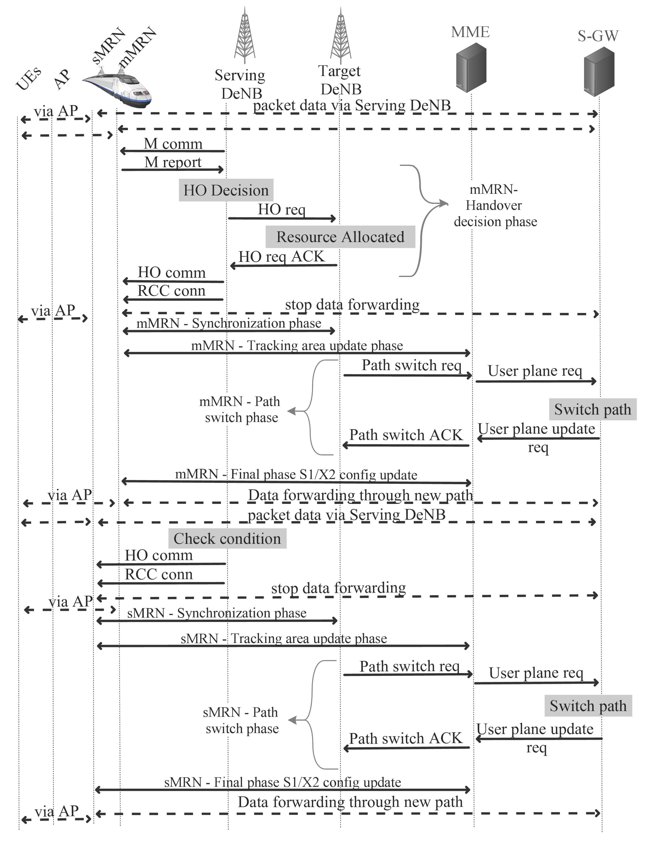
Figure 10 depicts the procedure used in the proposed HO scheme. The phases comprising the HO procedure are outlined below.
Figure 10.
Flowchart of the proposed HO scheme for dual MRNs.
Figure 10.
Flowchart of the proposed HO scheme for dual MRNs.
Decision phase: This phase begins when the serving DeNB receives a measurement report (M report) from the mMRN. On receiving the report, the serving DeNB makes the HO decisions using Event A3 and calculates the HO parameters using the proposed algorithm presented in Section 3.1. If the serving DeNB decides that the mMRN must perform the HO, then it sends an HO request (HO req) to the target DeNB. The HO request sent contains the HO parameters and context information for the target DeNB to prepare the resource allocation. After preparing the radio resource, the target DeNB accepts all MRNs and replies with an HO request ACK (HO req ACK) containing parameters for the serving DeNB and the HO procedure. Finally, the serving DeNB receives an HO request ACK and sends the HO command and radio resource control (RRC) connection reconfiguration (HO command, RRC conn) to the mMRN.
Synchronization phase: In this phase, the DeNB stops forwarding data to the mMRN; it does not serve data to the UEs inside of the vehicle during the HO procedure. Until the HO procedure of mMRN has been completed, only the sMRN serves the UEs. On completion, the mMRN tries to synchronize with the target DeNB by sending a synchronization command.
Tracking area update phase: On successfully synchronizing with the target DeNB, the mMRN sends a tracking area update command to the MME, which the MME uses to update the mMRN’s location.
Path switch phase: The target DeNB switches the routing path to the mMRN by sending a path switch update request (path switch req) command to the MME. On receiving this request, the MME issues a user plane request to the S-GW to switch the routing path. On completing the path switch, the S-GW replies with a user plane update message to the MME, which, in turn, sends a path switch request ACK message to the target DeNB.
Final phase: In the final phase, the mMRN updates its S1/X2 configuration. Then, the target DeNB and S-GW begin forwarding data along the new path to the mMRN. At this point, the HO procedure is complete.
4.3.2. sMRN Handover Procedures
On completion of the mMRN handover procedure, the serving DeNB places the sMRN in a wait state if the following conditions occur:
The velocity of the vehicle has decreased or the vehicle has stopped. In this case, the HO procedure of the mMRN is complete, and the UEs have been served. The sMRN continues connecting with the serving DeNB and served UEs.
The trajectory of the vehicle has changed. If possible, the mMRN makes a new measurement report to update candidate cells.
The reference signal received power (RSRP) of the target DeNB has decreased or the RSRP of another candidate DeNB is better than that of the target DeNB.
If the serving DeNB decides that the sMRN must perform the HO, HO procedures are initiated by the HO command (HO command) of the serving DeNB. The sMRN does not need to make a measurement report for the HO procedure. The HO in the sMRN procedure comprises the following phases:
Synchronization phase: After the sMRN receives the HO command and the RRC connection reconfiguration command (HO command, RRC conn), the serving DeNB stops forwarding data to the sMRN; the UEs are not served during the HO procedure. The sMRN will then try to synchronize with the target DeNB by sending a synchronization command.
Tracking area update phase: If the sMRN has successfully synchronized with the target DeNB, the mMRN sends a tracking area update command to the MME.
Path switch phase: In this phase, the target DeNB follows the HO procedure of mMRN.
Final phase: In this phase, the sMRN updates its S1/X2 configuration. Then, the target DeNB and S-GW start forwarding data along the new path to the mMRN, and the sMRN can complete its HO procedure.


