Mars to Earth Data Downloading: A Directory Synchronization Approach

DEI/ARCES, University of Bologna, Viale Risorgimento 2, 40136 Bologna, Italy
*
Author to whom correspondence should be addressed.
Future Internet 2019, 11(8), 173; https://doi.org/10.3390/fi11080173
Submission received: 26 June 2019
/
Revised: 29 July 2019
/
Accepted: 2 August 2019
/
Published: 8 August 2019
(This article belongs to the Special Issue Delay-Tolerant Networking)
Abstract
:This paper aims to present a possible alternative to direct file transfer in “challenged networks”, by using DTNbox, a recent application for peer-to-peer directory synchronization between DTN nodes. This application uses the Bundle Protocol (BP) to tackle long delays and link intermittency typical of challenged networks. The directory synchronization approach proposed in the paper consists of delegating the transmission of bulk data files to DTNbox, instead of modifying source applications to interface with the API of a specific BP implementation, or making use of custom scripts for file transfers. The validity of the proposed approach is investigated in the paper by considering a Mars to Earth interplanetary environment. Experiments are carried out by means of Virtual Machines running ION, the NASA-JPL implementation of DTN protocols. The results show that the directory synchronization approach is a valid alternative to direct transfer in interplanetary scenarios such as that considered in the paper.
1. Introduction
Delay/Disruption-Tolerant Networking (DTN) architecture originates from research on Inter-Planetary Networking (IPN). In the early 1990’s Kevin Fall proposed broadening the scope of IPN to embrace all “challenged networks” such as satellite and interplanetary networks, wireless sensor networks, tactical networks, opportunistic communications, emergency communications, underwater communications, etc. [1,2]. These networks are dissimilar, but have in common the fact that the TCP/IP architecture is challenged by one or more of the following impairments: long delays, frequent random losses (due to the channel), disruption, opportunistic contacts and network partitioning [3]. To cope with these problems, the DTN architecture introduces a new “Bundle Layer”, to be inserted between the Application and Transport layers of the ISO-OSI model. The new architecture was defined in RFC4838 [4] and its pillar, the Bundle Protocol (BP), in RFC5050 [5]. At present, standardization is carried out by IETF (Internet Engineering Task Force) [6] and by CCSDS (Consultative Committee for Space Data Systems) for space environments [7].
DTNbox is a DTN application developed by the authors, which aims to synchronize directories between DTN nodes [8]. It was designed to be peer-to-peer and robust against long delays and link disruption, not an easy task, as synchronization in general would clearly benefit from short latency and continuous links, exactly what is missing in challenged networks. As other applications of DTNsuite [9], DTNbox is fully compatible with all the major open source implementations of the BP: DTN2 [10], the original “reference” implementation of the IRTF DTN group; ION [11] by NASA-JPL; IBR-DTN, by the University of Braunshweig [12]. Although the rationale and features of DTNbox are fully described in [8], the advantages that can derive from its application to actual scenarios have not yet been investigated.
The idea explored in this paper is to use DTNbox as an alternative to direct data transfer for bulk data, which would have the advantage of decoupling data generation from transmission. If the source already generates bulk data as files (e.g., images or results of scientific experiments), these files could be put into a synchronized directory and then automatically transferred to destination by means of DTNbox. This way there would be no need to modify the data generation program to interface it with the API of one of the BP implementations, or to write custom scripts for file transfers, which would be feasible but peculiar to each application and probably not as robust as DTNbox. The disadvantage is that indirect file transfer necessarily adds some delay to delivery, which is the reason why this solution is not appealing in ordinary networks where connectivity is continuous and delays are of the order of only very few milliseconds. By contrast, in a challenged network, propagation delays can be huge (minutes or hours) and disruption can force bundles to be stored for long periods at intermediate nodes, waiting for a new contact to the next node. For both reasons, the additional delay due to indirect transmission can become negligible, which makes the directory synchronization solution appealing, at least for bulk data, for which fastest delivery is not the primary concern.
To assess validity of the proposed DTNbox-based approach, we have preferred to rely on a scenario already investigated instead of building an “ad hoc” scenario from scratch, thus avoiding by root any possible bias. To this end, we have considered a simplified variant of the Earth-to-Mars scenario already studied in the context of the “Delay tolerant network for flexible Communication with Earth Observation satellites” project funded by ESA/ESOC [13], whose results were preliminary presented in [14] and then fully analyzed in [15]. This scenario is much more complex than the basic Martian scenario studied in [16], and was built by merging inputs form ESA/ESOC with the experience of other partners of the project, including GMV, DLR, Solenix and University of Bologna. Even in the simplified version considered here, this scenario is quite representative of future interplanetary environments, which is essential to draw general conclusions about the real applicability of the proposed approach in space.
Experiments were carried out using a virtual testbed consisting of a few Linux based virtual machines (VMs), running ION, the BP implementation developed and maintained by NASA-JPL. Performance was assessed largely by the analysis of “status reports” [5], i.e., informative bundles optionally generated by DTN nodes to track bundle transmissions, and data file creation logs (for DTNbox). The results achieved are discussed in detail in the paper.
The rest of the paper is organized as follows: in Section 2 we present a brief summary of DTNbox in Section 3 we describe the space scenario in the experiments; in Section 4 the direct and indirect approaches are compared, with explicit reference to this scenario; experiments are described in Section 5, and results analyzed in Section 6. Conclusions are finally drawn in Section 7.
2. DTNbox
DTNbox [8] is part of DTNsuite [9], a set of DTN applications developed by the University of Bologna, including DTNperf [17], a performance evaluation tool also used in this paper. These applications are based on an abstract interface to BP, called Abstraction Layer, which is part of the DTNsuite as well. This abstracted API allows DTNsuite applications to be decoupled from the specific BP implementation in use, either DTN2, ION or IBR-DTN, which facilitates maintenance and greatly extends their portability.
The basic aim of DTNbox is to synchronize two directories on two DTN nodes belonging to a challenged network. The two nodes can be quite distant from each other, such as a node on Mars and another on Earth, as considered later. Communications between them is performed using the Bundle Protocol and may involve multiple DTN hops, with intermediate DTN nodes acting as DTN routers.
Although inspired by analogous programs on Internet, with which DTNbox shares the aim of directory synchronization, it differs considerably from them because it is peer-to-peer, as it would be impossible to use a centralized server on a challenged network, it does not require direct communication between the two synchronized nodes; it can cope with long delays and link intermittency. DTNbox is released as free software under GPLv3 license.
The DTNbox basic use is to create bilateral synchronization, thus we will start our description from here.
2.1. Bilateral Synchronizations: Owner and Local Copies
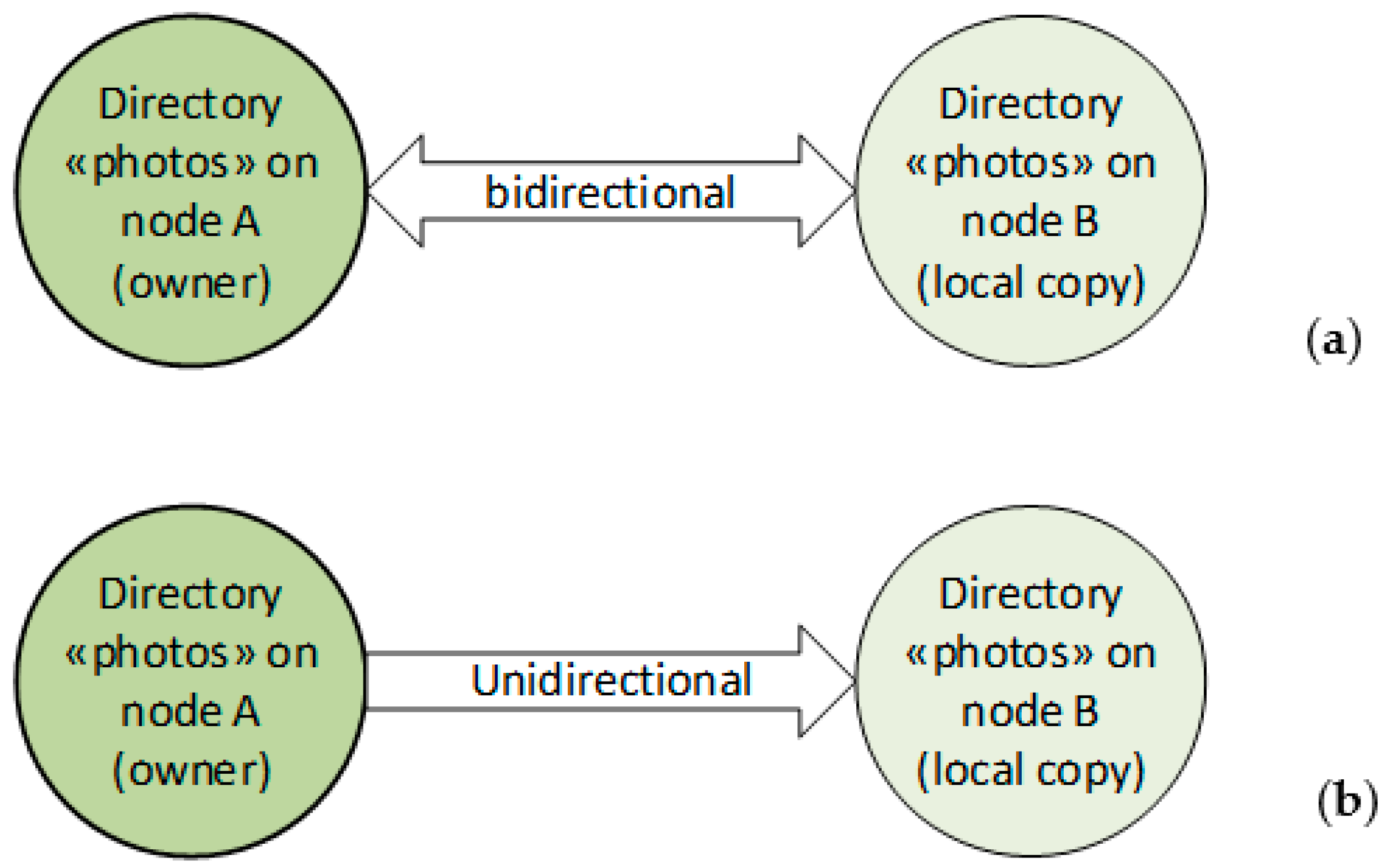
In “bilateral” synchronizations only two nodes are involved: the “owner” of the directory that is synchronized, and the other node, which has only a local copy. Bilateral synchronization can be either bidirectional or unidirectional. In the former case (Figure 1a), all the changes made on either of the two paired directories are mirrored in the other. By contrast, in the latter (Figure 1b), changes on the local copy are not mirrored on the owner directory.
The concept of owner is paramount in DTNbox. Synchronized directories must be in a specific position in the file system (e.g., /DTNbox/FoldersToSynch/nodeA/photos). This constraint is justified by two advantages: (a) it allows DTNbox to clean the file system automatically when a synchronization is closed (the original on the owner node is maintained, while local copies are cancelled; (b) it greatly facilitates the establishment of multilateral synchronizations.
2.2. Multlateral Synchronizations
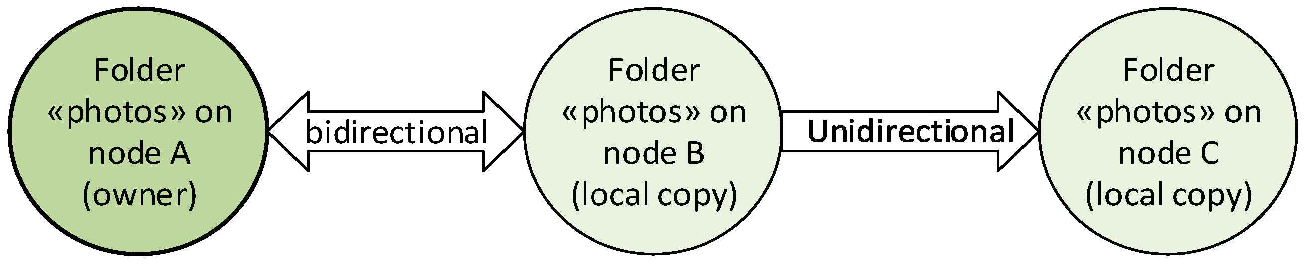
These are created by extending bilateral synchronizations to other nodes. For example, by extending the previous bilateral synchronization involving A and B to C, we can obtain the tri-lateral synchronization shown in Figure 2. The extension can be either bidirectional or unidirectional. We will see a possible use for this feature at the end of the experiment section.
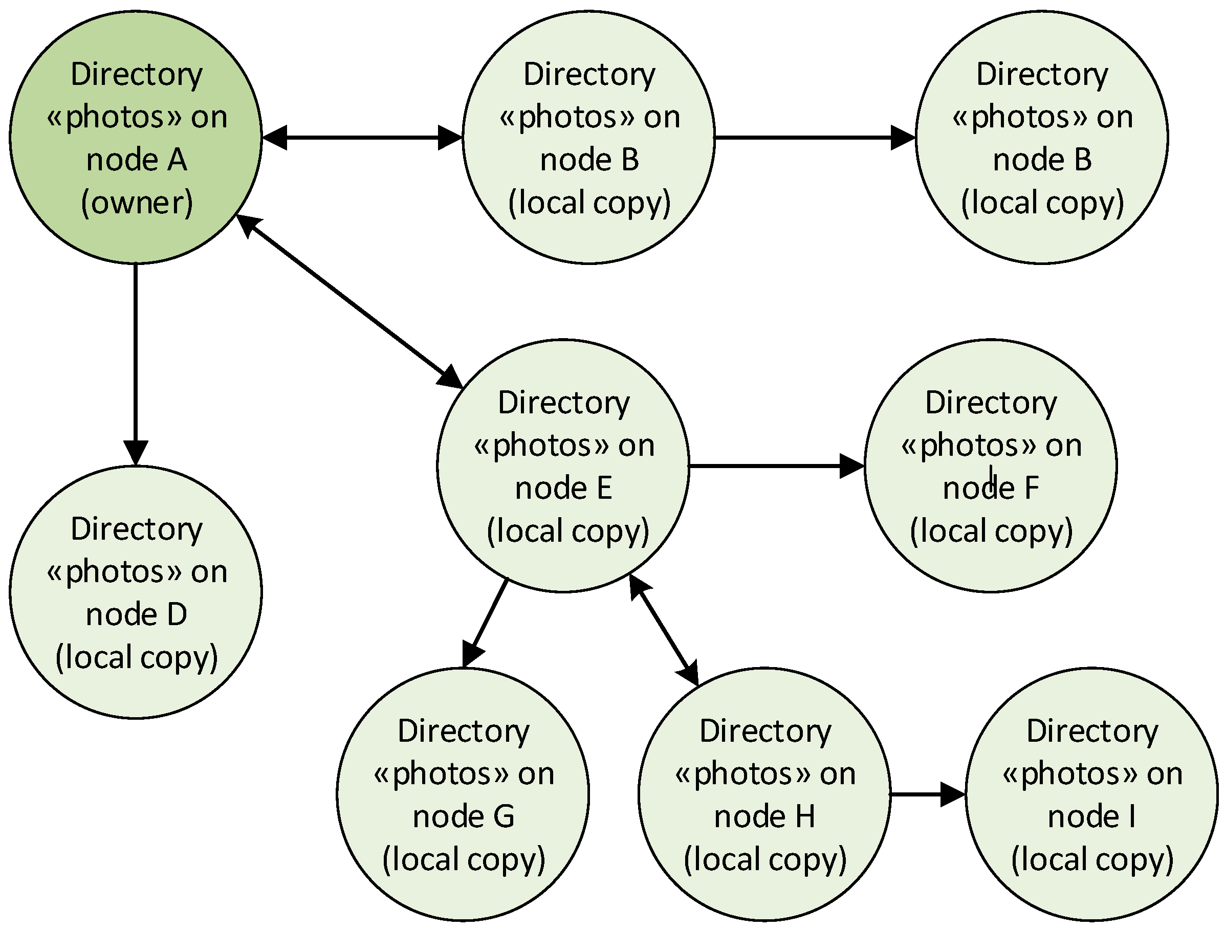
More generally, as a result of multiple extensions, a tree of multilateral synchronizations (bidirectional or unidirectional), can be established, as that shown in Figure 3. To avoid loops DTNbox sets automatic constraints on possible extensions.
2.3. Challenges and Countermeasures
DTNbox, like all synchronization programs, must keep track of the state of synchronizations. To this end it uses an external relational database, based on SQLite. Every synchronization necessarily involves an exchange of information between synchronized nodes, consisting of file updates, commands (e.g., to establish or close a synchronization) and command acknowledgments. The real difference when dealing with a challenged network is that this exchange is much more difficult than usual, because of channel impairments, such as long delays and link intermittency. In challenged networks the time elapsed between sending of a command (e.g., a file update) and corresponding acknowledgment reception can be very long, e.g., in the order of minutes or even hours, instead of a few tens of ms as in Internet. Therefore, it is necessary to reduce DTNbox chattiness to a minimum and to use the DTN architecture and the Bundle Protocol. To this end, DTNbox aggregates commands and file updates in one tar file at regular intervals (in our test every 5 s), and then sends it to the synchronized node in one bundle [8]. This way the overhead is reduced, as commands, acknowledgments and file updates can be multiplexed in one bundle.
2.4. BP Settings and Retransmission Features
2.4.1. Bundle Lifetime and Other BP Settings
DTN bundles have a lifetime, in seconds, after which they are automatically discarded [5]. Because the time to reach destination in a DTN network varies significantly with the destination, e.g., because of the presence of the absence of interplanetary links in the route to it, the DTNbox user can set a specific lifetime to each destination. A trade-off between two different needs must be achieved. On the one hand, the lifetime should be a little longer than the expected delivery time to that destination to prevent premature bundle dropping because of lifetime expiry; on the other hand is should not be too long, so as not to excessively delay possible DTNbox retransmissions when needed (see below). Other parameters specific to BP, such as priorities, custody option, status reports, etc. [5], at present are set in the DTNbox code, but are going to be made available in the next release.
2.4.2. DTNbox Acknowledgments and Retransmissions
In a DTN network, the end-to-end path to destination is divided into multiple DTN hops and hop-by-hop reliability is enforced by BP using a reliable transport protocol on each hop, such as TCP or LTP “red” [18,19]. However, proper end-to-end reliability requires acknowledgments from destination. Therefore, on the destination node DTNbox acknowledges all file updates and a few selected important commands. If these acknowledgments are not received in time, DTNbox retransmits the unacknowledged data. The retransmission timeout is automatically set to twice the bundle lifetime, as after this time it is impossible to receive any acknowledgment (one lifetime for the original data, another for the acknowledgment). Multiple retransmission can be carried out, as usual, until a threshold is reached. The total number of transmissions can also be set according to the destination. By not allowing any retransmission, the user can disable this feature to rely only on BP mechanisms.
3. Mars to Earth Scenario
The Mars to Earth scenario considered here derives from that used in the ESA/ESOC project “Delay tolerant network for flexible Communication with Earth Observation satellites”, described in [14,15]. Given the different aim of the present paper, this scenario has been slightly simplified to consider only one Mars orbiter instead of two.
3.1. DTN Topology and Links
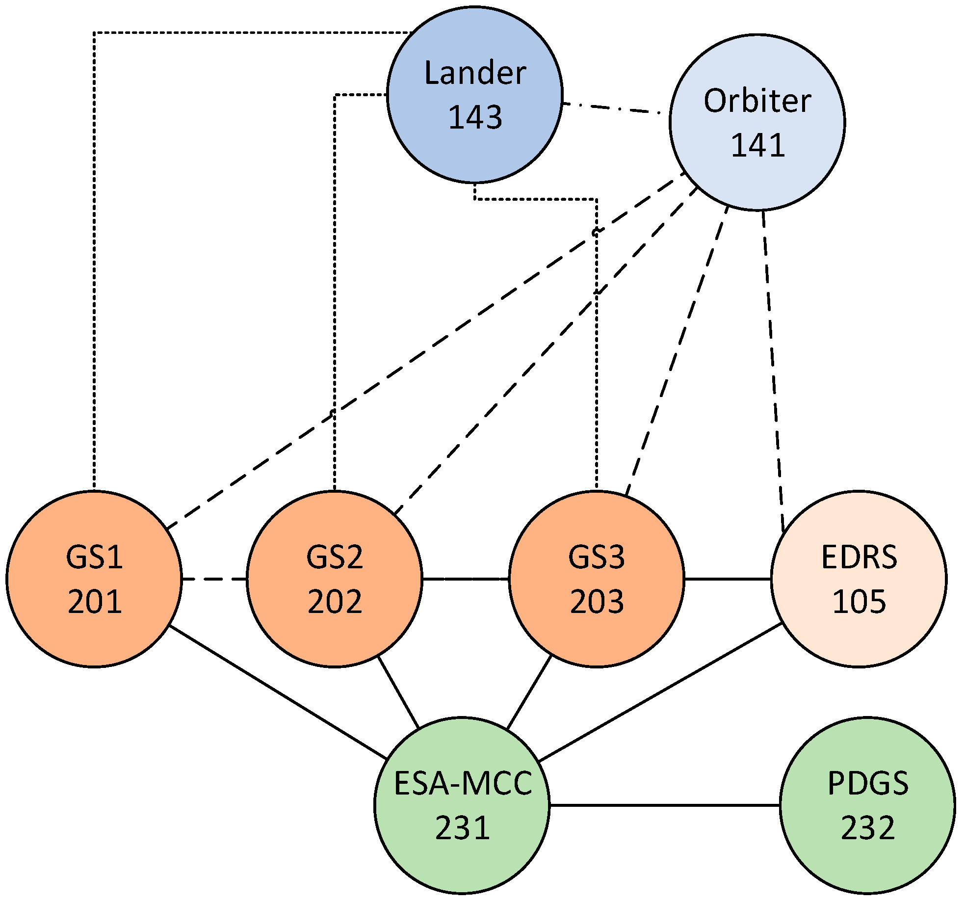
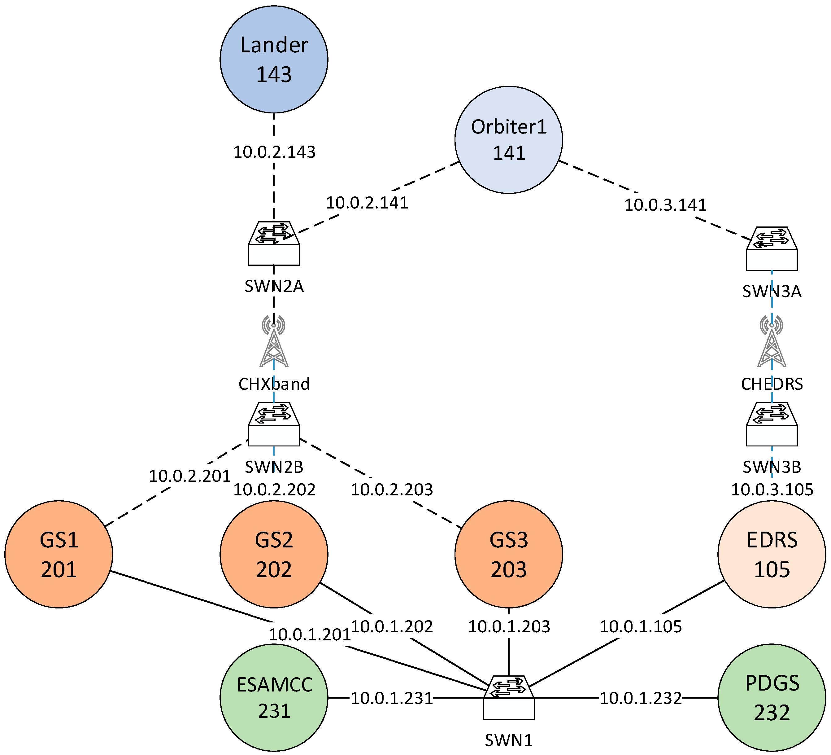
The DTN layout is shown in Figure 4. There are two regions, Mars and Earth. The former consists of one lander (Lander node) and one Mars orbiter (Orbiter). The terrestrial segment consists of four relays, three ground stations (GSs) and the European Data Relay Satellite GEO satellite gateway (EDRS), and two destinations: the ESA (European Space Agency) Mission Control Center (ESA-MCC) and the ESA Payload Data Ground Segment (PDGS). EDRS is used here more as a symbolic name than to actually denote the current EDRS system [20] and analogously for the PDGS node. In the figure, dotted or dashed lines denote intermittent space links where LTP is used; continuous lines represent continuous terrestrial links, with TCP. Note that the Orbiter is connected to the four terrestrial relay nodes, while the Lander is connected both to Orbiter and to GSs, but not directly to EDRS.
Link settings are presented in Table 1. While the delay on both Earth and Mars links is assumed negligible, on interplanetary links is very long because the two planets have been considered at their maximum distance, namely about 23 min, it will be scaled down to 23 s in the experiments for convenience. Negligible losses are assumed on all links. Transmission rates vary considerably, as expected. The three interplanetary direct links between Lander and Ground stations have a very limited bandwidth in both directions (only 32 kbit/s); the shorter Lander to Orbiter link is much faster (2 Mbit/s), again in both directions; the Orbiter to terrestrial relays (GSs and EDRS) links are fast in downlink (2 Mbit/s) but very slow in uplink (32 kbit/s).
3.2. Mission Application Data Flows. For Convenience, Original Propagation Delays, in Minutes, Were Scaled-Down by a Factor of 60, i.e., Interpreted as Minues, in the Experiments
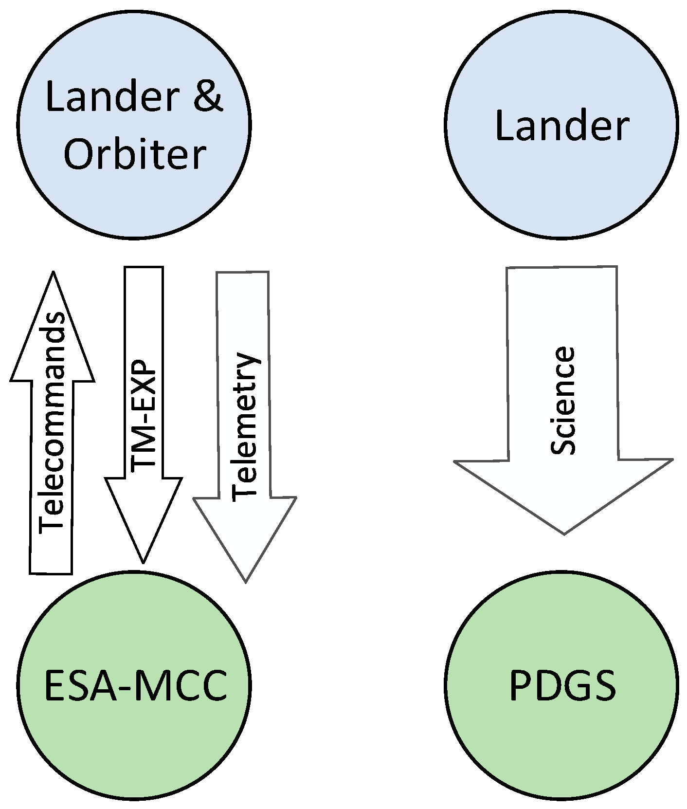
Data flows are summarized in Figure 5. Both the Lander and the Orbiter receive Telecommands (TC) from the ESA-MCC and send back Urgent Telemetry (TM-EXP). These flows consist of small bundles with low generation rates (see Table 2) and, being urgent, they have “expedited” priority. Telemetry (TM) is also generated on board both space assets and sent to ESA-MCC, but has different characteristics, with larger and more frequent bundles, with “normal” priority. Last, we have the science flow, from Lander to PDGS. It consists of much larger bundles with “bulk” priority, with the highest generation rate. The focus of the experiments presented here will be on this flow, delivered either directly to destination, by means of DTNperf, or alternatively, by means of DTNbox directory synchronization. The other six flows are destined to act as background traffic, to make the scenario more realistic. Data flow characteristics are summarized in Table 2.
3.3. Contact Plan
The contact plan used in the experiments is a subset of that used in [15] (it lacks the contacts to and from a second orbiter, not considered here), with only few adjustments on the Tx rates to compensate the lack of the second orbiter. Original contacts were calculated using an orbital simulator based on EOTOOL by GMV [21]. To keep the length of the experiment manageable, these contacts have been time-scaled down in experiments by a factor of 60, as propagation delays (i.e., we have seconds instead of minutes and minutes instead of hours), as done in [14,15]. This way the 24-h interval of the original contact plan corresponds to an actual experiment length of 24 min (1440 s). Note that link speeds (Table 1) have not scaled down, as this would not have helped in reducing the original length of the experiment.
A few technical considerations about the correctness of scaling down contact lengths and propagation delays are most likely useful, to reassure the reader that by them we have not altered the behavior of the system. First, it is true that by reducing the contact times we have also reduced the contact volumes, i.e., the amount of data (in bytes) that can actually be transferred during a contact. However, as the length of the experiment is automatically reduced by the same factor, it is also correspondingly reduced the total amount of data generated, and thus preserved the balance between traffic load and network capacity, which is the essential aspect. Second, concerning the reduction of propagation delays, this is uninfluential if there are no losses on the links, as assumed here.
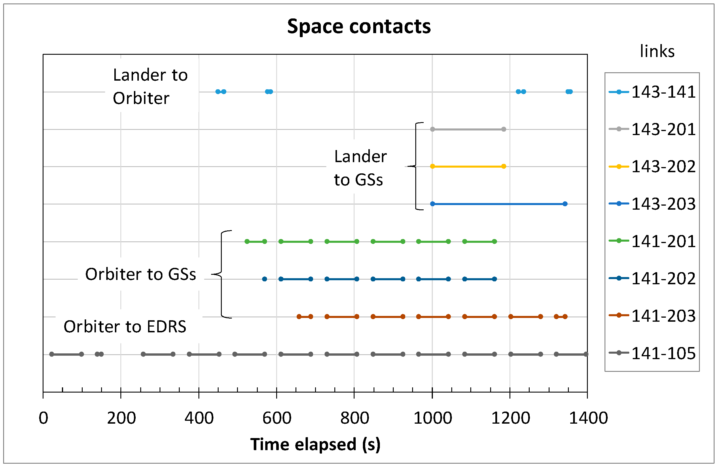
Let us now examine the characteristics of scaled-down space contacts, plotted in Figure 6 as horizontal segments. Between the Lander (143) and the Orbiter (141) connectivity is very scarce, due to the fast orbital speed of the Orbiter. We have only two short pairs of contacts (first pair after 400 s, second at about 1200 s). Their very short duration limits their contact volumes. The Lander is also directly connected to the three GSs (201, 202, 203), with one long contact each, starting towards the end of the experiment (from 1000 s). Contacts between Orbiter (141) and GSs are much more frequent, and even more frequent for the link to EDRS (105), whose contacts are also uniformly distributed over time, with a significant gap only at 200 s.
Considering that contacts from Lander to Orbiter are few and short, and that there is only one contact between Lander and each GS with a very limited bandwidth (only 32 kbit/s), it is clear that the connectivity of the Lander, in terms of total contact volumes available is critical. However, it is still compatible with the amount of traffic generated on board of the Lander. This makes the scenario particularly interesting to compare the DTNbox-based approach to the traditional one.
4. Comparison of Direct and DTNbox Approaches for Bulk Data Transfers
Our aim is to demonstrate that in an interplanetary environment the DTNbox approach, based on directory synchronization, offers significant advantages in terms of flexibility with almost the same performance of direct data transfer in terms of delivery time. Let us compare the two approaches with reference to the space scenario described above.
4.1. Direct Approach
In the DTN experiments, data generation and dispatch to destination are usually coupled. The application that generates the data is also sends the data to the destination node using the BP the advantage of this direct approach is that it ensures the minimum delivery time; the disadvantage is that the application that generates the data must be “DTN aware”, i.e., it must be designed to interface directly with the API of BP.
4.2. DTNbox Approach (Alternative Way)
When data are generated as large bulk data files, an alternative approach is to decouple file generation from file sending, by letting DTNbox carry out the file transfer task. It is enough to establish a bilateral synchronization between the source and the destination nodes. The two directories must be devoted to a specific application. Once a new file is generated (e.g., an image on the Lander), DTNbox will transfer it to the synchronized directory on the destination node (e.g., PDGS). Here, the application can read the file and move it onto another directory for long-term storage. In this way, the file is deleted form the “local copy” directory, and, if synchronization is bidirectional, after a while the file will be deleted on the owner directory, on the source node, thus completing the file transfer process.
The advantage of the DTNbox approach is that by decoupling data generation from dispatch, scientific appliances (e.g., cameras, data loggers, etc.) can be directly used, with no need to build custom versions directly interfaced with the API of the Bundle Protocol. We can also avoid the use of custom scripts, which would lack the features of DTNbox, to download files via BP. There are only two requirements: data must be generated as files, the application must be delay-tolerant, i.e., it must allow for possible additional delay due to DTNbox processing. This is why this approach is particularly appealing for bulk data, which are usually generated as files and are low priority.
5. Experiment Description
5.1. Virtual Testbed Description
To carry out the experiments we used a GNU/Linux virtual testbed created by Virtualbricks [22]. The testbed consists of eight Virtual Machines (VMs), one for each DTN node, connected by virtual switches and channel emulators, which are essential for adding the desired delay on Mars to Earth links (see Figure 7). VM clocks are perfectly synchronized, as VMs set their clocks from the host. All VMs run GNU/Linux and ION, the NASA implementation of the DTN architecture, including BP, LTP and CGR. The last is a routing algorithm specifically designed by NASA JPL to cope with scheduled intermittent connectivity, typical of space networks. We used ION 3.6.0 b [11], with a patch to fix problems encountered during previous tests. DTNsuite including DTNbox and DTNperf is also installed on all nodes.
5.2. Data Flow Generation
5.2.1. Direct Approach
With the direct approach each data flow is generated by an instance of the DTNperf client [17] (7 in total), which allows the user to set the specific parameters of the data flow, such as destination, priority, bundle dimension and generation rate. Bundles are received by one of the four instances of the DTNperf server, running on Lander, Orbiter, ESA-MCC and PDGS. Status reports are collected by a DTNperf monitor on ESA-MCC. The whole experiment is managed by a “do-test” script running on the host, which is connected to all VMs by means of a dedicated control network, with ideal links (no delay, no losses, no disruption).
5.2.2. DTNbox Approach
As the DTNbox approach is particularly suited to bulk data, it is applied only to the Science data flow, from Lander to PDGS. Aiming at maximum communality, Science data is generated by DTNperf as in the direct approach, except that this time the destination is not the DTNperf server on the PDGS node, but an instance of the ION “bpreceive” application [11], running on the synchronized directory (DTNbox/filesToSynch/143/Science). Bpreceive saves the payload of received bundle in a new file (testfile1, testfile2, etc.). Then, at regular intervals (in our tests 5 s), updates containing new files are sent by DTNbox to the synchronized directory on PDGS. Here new files are moved to another directory by a script running in the background, which emulates the receiving application. At the end of experiment, a record of file creation times is extracted from this directory, to derive the file delivery times to compare with those of the direct approach.
5.3. Status Reports, Data Collection and Processing
Bundles have no size limits and are generally larger and fewer than IP packets. They can be tracked in tests by status reports, which are extremely valuable for performance analysis. A status report is an administrative bundle containing information about the time when a specific data bundle is either received, forwarded, taken into custody, deleted, or delivered [5]. The source application can enable the generation of status reports by setting the corresponding request flags in the bundle primary block. Each status report always contains the source EID (End point IDentifier) and the generation timestamp of the data bundle to which it refers, as well as one or more additional timestamps. Status reports are collected by the DTNperf monitor into a csv file for further analysis. This file is then processed by a data-sheet application, to extract the desired information and plot the graphs.
6. Performance Analysis
In order to introduce the reader to the space environment considered, let us start the analysis with the TM-EXP flow, the simplest one.
6.1. TM-EXP Data Flow
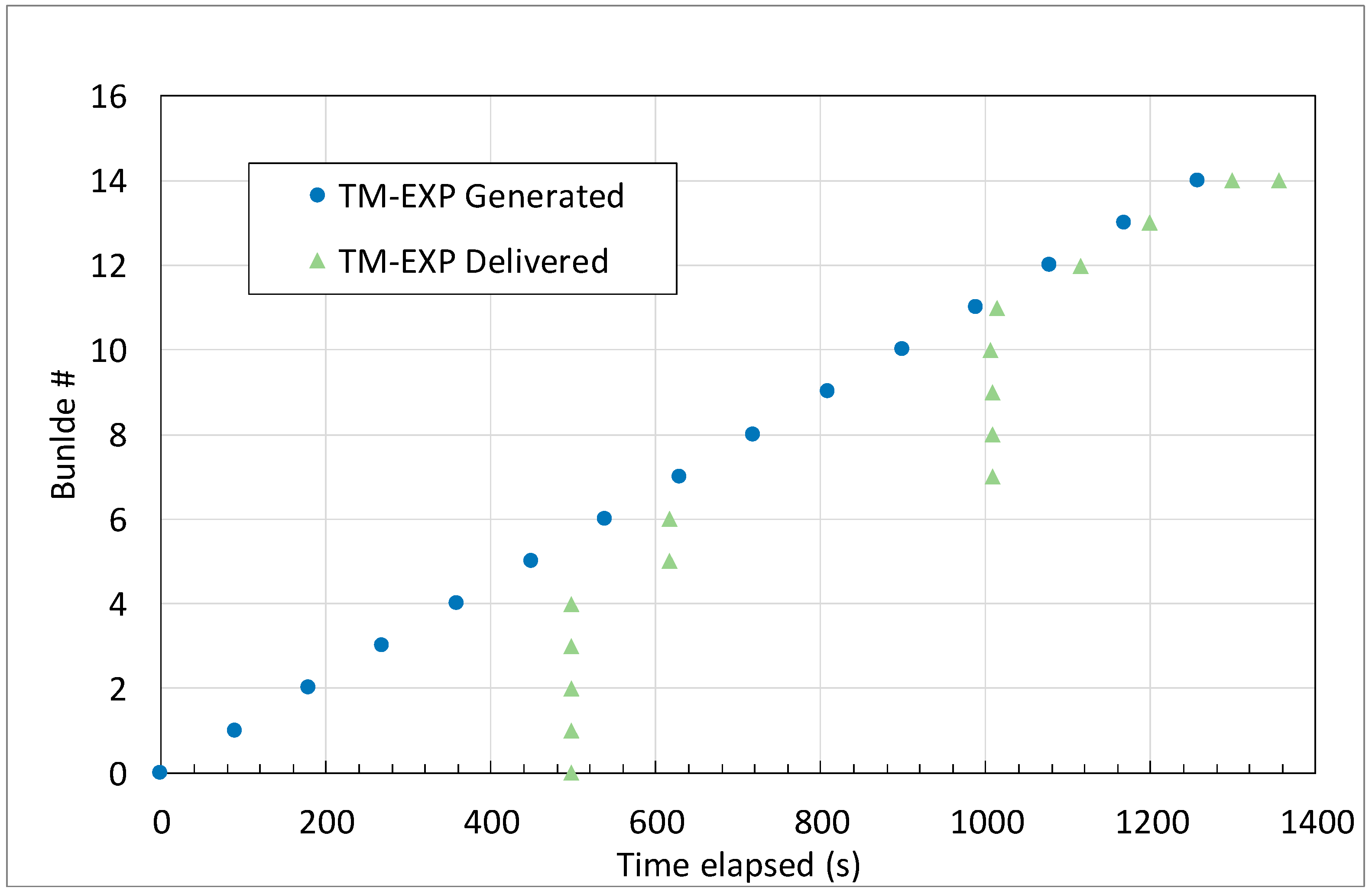
In Figure 8 we have plotted two series, “TM-EXP generation” and “TM-EXP delivery”. For each bundle we have two markers on the same horizontal line, as the ordinate is the bundle number. The interval between these two markers denotes the time elapsed from generation to delivery, i.e., the delivery time. Bundle generation is performed at regular intervals, while delivery is in bursts, due to intermittent connectivity of space links. No bundles are delivered before about 470 s, as the first opportunity to leave the Lander is offered by the first contact with the Orbiter, at 440 s (see Figure 6). Bundles generated before this time must be stored by the bundle protocol and wait for the contact to open. When this happens, all bundles are almost immediately passed to the Orbiter (the propagation delay between Lander and Orbiter is negligible), and then from the Orbiter to ESA-MCC. Here the propagation delay is longer (23 s) but connectivity is very good, as contacts from the Orbiter to the three GSs or EDRS are many and with small gaps. The best route is dynamically selected, bundle-by-bundle by CGR [15,23]. The same happens for bundles generated after closure of the first contact to the Orbiter, which have to be stored on board until the second Lander-to-Orbiter contact opens (bundles 5 and 6) and then for those generated after its closes and before the direct contacts from Lander to the three GSs open. After the burst of old bundles (7–10) waiting for this opening, new bundles are delivered either via direct contact to GSs or via Orbiter 1 at regular intervals.
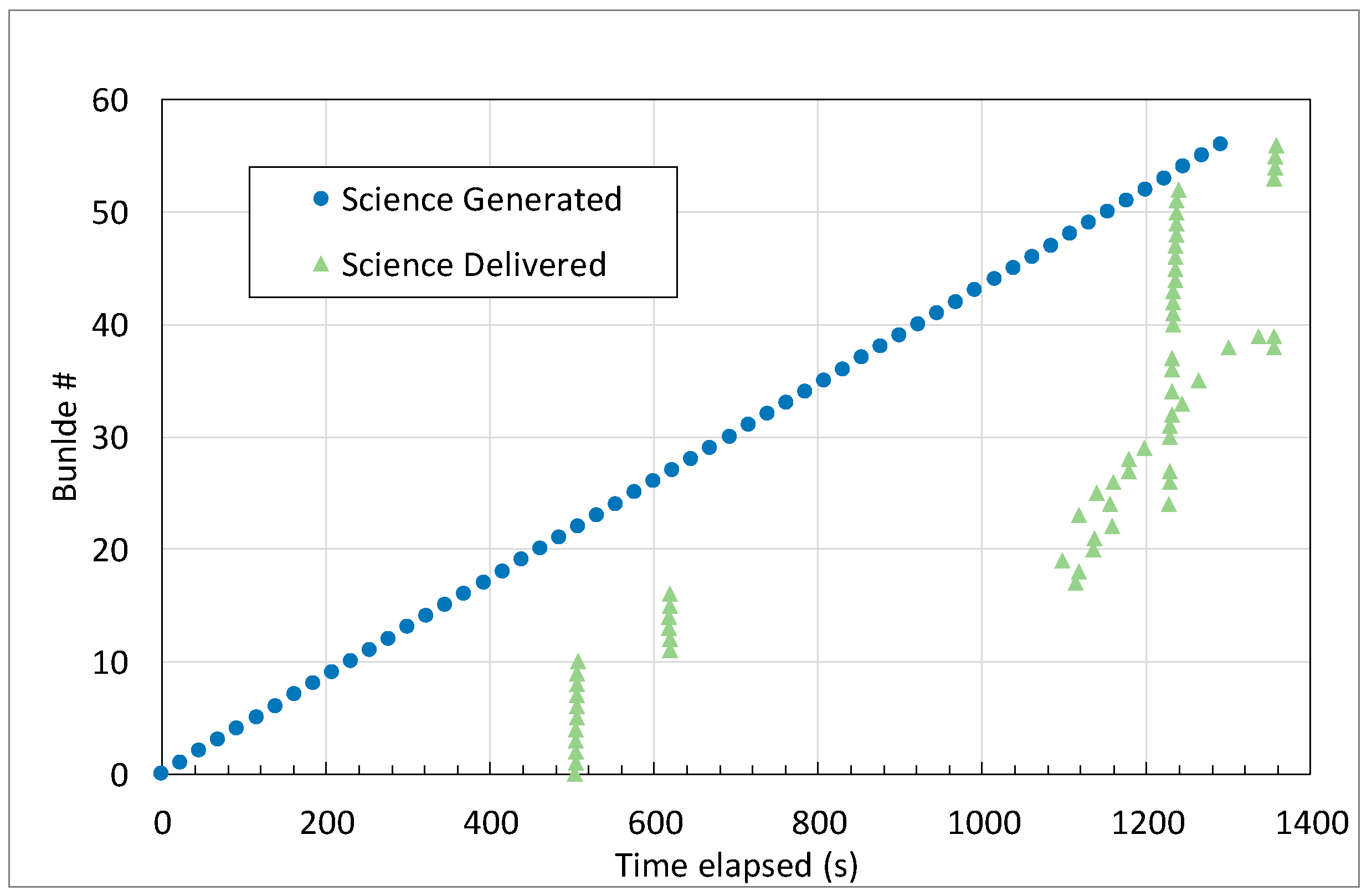
6.2. Science Data Flow (Direct Delivery)
Now we can move on to the science data. First, we will examine the case of direct delivery using DTNperf, which is our benchmark case (Figure 9). Bundles are much more frequent (about one every 21 s) than in the previous case. Because of limited connectivity from the Lander, there are th0e same two delivery gaps as before. The main difference is that now bundles are often delivered out of order. Although this is allowed by DTN specifications [5], this is a symptom of the challenges posed by concurrent traffic. In fact, while gaps are due to lack of connectivity, disordered delivery is mainly the result of concurrent bundles of higher priority, which are always forwarded first, even if generated later, thus making delivery predictions for lower priority bundles inaccurate. In this regard, it must be stressed that CGR decides on the best route (i.e., that which should reasonably ensure fastest delivery, given the contacts in the contact plan) bundle-by-bundle, as soon as the bundle arrives at the local node [23]. CGR cannot therefore take account of the forwarding delay due to higher priority traffic that appears later. As a last positive remark, we can note that all bundles are delivered by the expected end of the experiment.
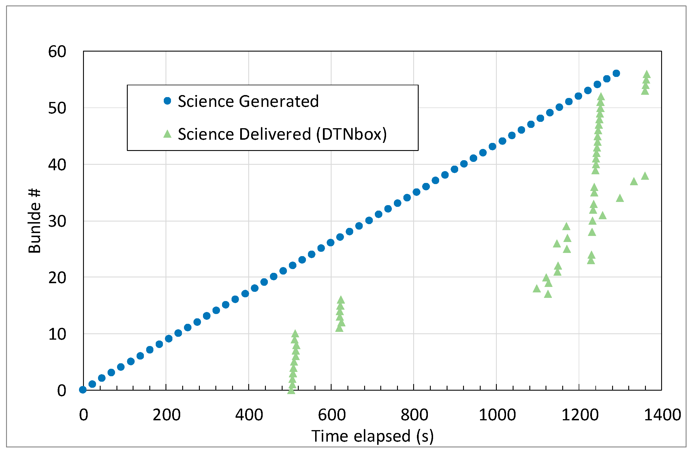
6.3. Science Data Flow (DTNbox Approach)
Now, let us examine the case of alternate delivery via DTNbox, which is the focus of this work. Although delivery results (Figure 10) are not exactly the same as before (Figure 9), which would have been impossible because the transmission mechanism is different, they are very similar. Comparing the two figures, it is evident that the delivery time penalty due to indirect delivery via DTNbox is negligible in space environments. In particular, the delivery of all 57 bundles is completed in roughly the same time as in the previous case (by inspection of numerical data we can see that it takes just 6 s more) although larger variations can be found on single bundles.
In more details, it must be noted that the DTNbox processing time is essentially due to the fixed interval between updates (5 s), and thus can be safely assumed uniformly distributed in this range. Link intermittency, however, can either eliminate or expand this delay because bundles cannot be transmitted with continuity, but only when the link to the next node opens. Therefore, if the contact to the next node is closed, the DTNbox processing delay does not translate into an actual transmission delay (and eventually in a delivery time penalization). By contrast, in the unlucky opposite case, a small processing delay can result into a huge delivery time penalization, if it causes the missing of a contact. In brief, we can say that in an intermittent environment everything goes as in a journey consisting of multiple flights. If there is a delay in the landing of one flight, this can be either uninfluential if we can still take the connecting flight, or substantial, if, however small the delay, we miss the connection.
Note that as actual penalizations depend on the contact plan, it would be impossible to derive statistical evaluations with a general scope from results achieved. However, as the numerical result obtained refer to a scenario quite representative of future interplanetary networks, the authors are reasonably confident that the evaluations reported here can have a general value.
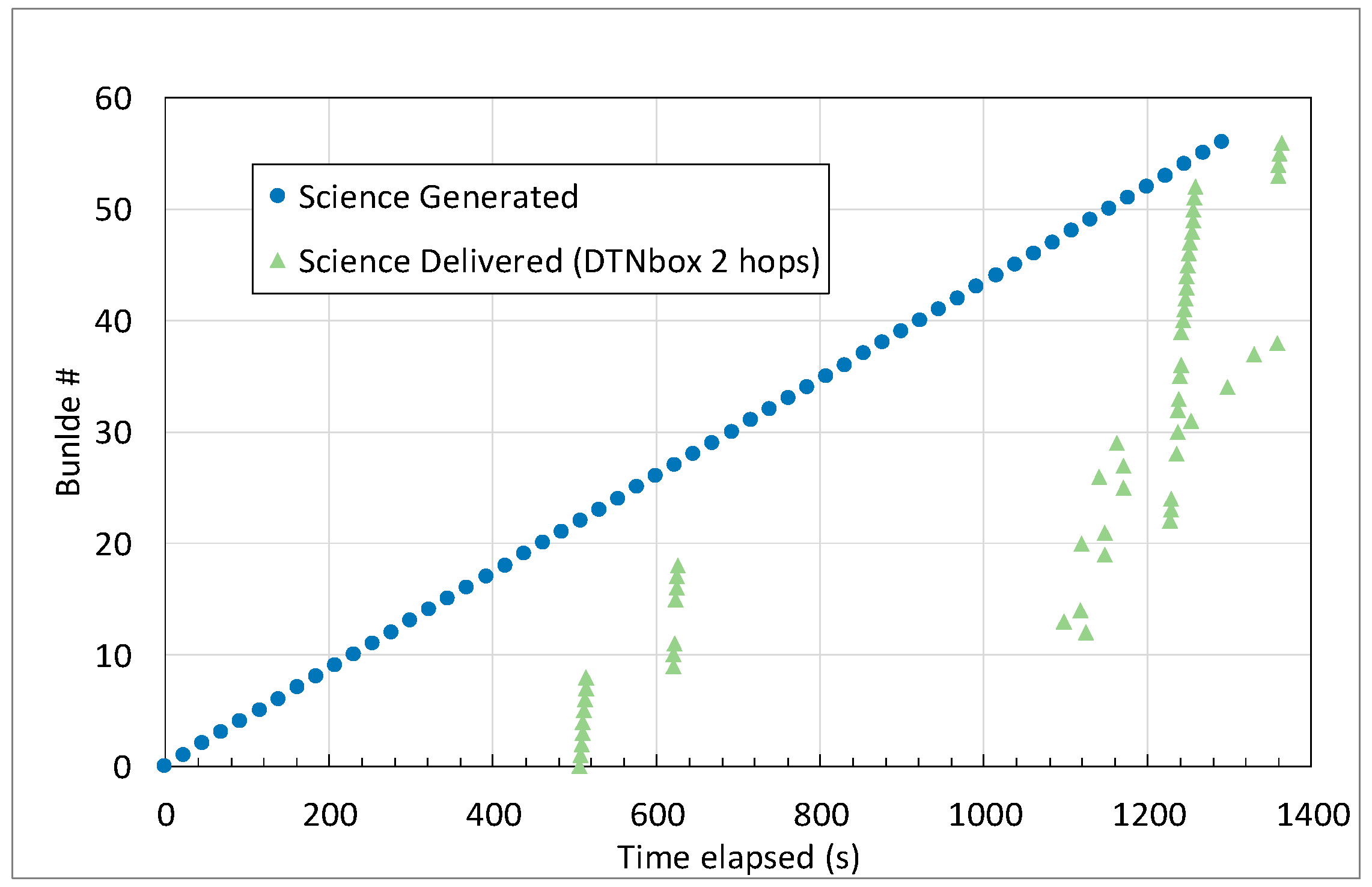
6.4. Science Data Flow (DTNbox Approach, Multilateral Synchronization)
These encouraging results have led us to introduce a variant in the experiment, to examine performance in the case of two DTNbox synchronization hops. In this variant, instead of bilateral synchronization between Lander and PDGS, we have multilateral synchronization similar to that illustrated in Figure 2, with a first synchronization hop from Lander to ESA-MCC and a second hop from ESA-MCC to PDGS. The results are shown in Figure 11. Comparing delivery results with those in Figure 10 (one synchronization hop between ESA-MCC and PDGS), we can observe that the qualitative behavior is still the same and that the average penalization due to the second synchronization hop is marginal (only about 5 s more, i.e., 15 s more than in the direct transfer).
The advantage of this scheme, with respect to direct delivery to both ESA-MCC and PDGS nodes, is that original bundle payloads are sent on space links only once (from Lander to ESA-MCC), instead of twice (to ESA-MCC and to PDGS). Thus, the DTNbox approach seems particularly appealing where there is one sender in space and multiple destinations on Earth.
7. Conclusions
This paper proposes a new method for data downloading in challenged networks, as an alternative to direct file transfer or to custom scripts. It is based on DTNbox, a DTN application for directory synchronization, recently implemented by the authors. The advantage of the proposed approach is that it decouples data generation from actual transmission, now completely delegated to DTNbox. The only requirements are that the source application save its data as files (e.g., images or experiment results), and that it be delay-tolerant. Coping with the challenges of the network is left entirely to DTNbox. The validity of this approach has been assessed by considering a complex Mars to Earth scenario, representative of future space missions. The results obtained, using a virtual testbed, show that the delay added by DTNbox processing is negligible. This confirms the validity of the proposed directory synchronization approach, as an alternative to direct data download, in interplanetary environments.
Author Contributions
M.B. is the main developer of DTNbox; C.C. is the principal investigator and the research coordinator.
Funding
This research received no external funding.
Conflicts of Interest
The authors declare no conflict of interest.
References
- Fall, K. A delay-tolerant network architecture for challenged internets. In Proceedings of the 2003 Conference on Applications, Technologies, Architectures, and Protocols for Computer Communications, Karlsruhe, Germany, 25–29 August 2003; pp. 27–34. [Google Scholar] [CrossRef]
- Burleigh, S.; Hooke, A.; Torgerson, L.; Fall, K.; Cerf, V.; Durst, B.; Scott, K. Delay-tolerant networking: An approach to interplanetary internet. IEEE Commun. Mag. 2003, 41, 128–136. [Google Scholar] [CrossRef]
- Fall, K.; Farrell, S. DTN: An Architectural Retrospective. IEEE Jorn. Select. Areas Commun. 2008, 26, 828–836. [Google Scholar] [CrossRef]
- Cerf, V.; Hooke, A.; Torgerson, L.; Durst, R.; Scott, K.; Fall, K.; Weiss, H. Delay-Tolerant Networking Architecture. Internet RFC 4838. 2007. Available online: http://www.rfc-editor.org/rfc/rfc4838.txt (accessed on 25 June 2019).
- Scott, K.; Burleigh, S. Bundle Protocol Specification. Internet RFC 5050. 2007. Available online: http://www.rfc-editor.org/rfc/rfc5050.txt (accessed on 24 June 2019).
- Internet Engineering Task Force DTN Working Group (DTNWG). Available online: https://datatracker.ietf.org/group/dtn/documents/ (accessed on 25 June 2019).
- CCSDS DTN Working Group. Available online: http://cwe.ccsds.org/sis/ (accessed on 25 June 2019).
- Bertolazzi, M.; Caini, C.; Castellazzi, N. DTNbox: A DTN Application for Peer-to-Peer Directory Synchronization. In Proceedings of the IEEE Wireless Days 2019, Manchester, UK, 24–26 April 2019; pp. 1–4. [Google Scholar] [CrossRef]
- DTNsuite Code (Including DTNbox). Available online: http://cnrl.deis.unibo.it/software.php (accessed on 25 June 2019).
- DTN2 Web Page on Sourceforge: DTN Tolerant Networking. Available online: https://sourceforge.net/projects/dtn/files/ (accessed on 25 June 2019).
- ION Web Page on Sourceforge, ION-DTN Delay-Tolerant Networking Suitable for Use in Spacecraft. Available online: https://sourceforge.net/projects/ion-dtn/ (accessed on 25 June 2019).
- IBR-DTN Project Web Page. Available online: https://github.com/ibrdtn/ibrdtn/wiki (accessed on 25 June 2019).
- Web Site of the Delay Tolerant Network for Flexible Communication with Earth Observation Satellites Project, Funded by ESA/ESOC (Contract Number 4000121303/17/F/MOS). Available online: https://nebula.esa.int/ content/delay-tolerant-network-flexible-communication-eo-satellites (accessed on 25 June 2019).
- Alessi, N.; Caini, C.; de Cola, T.; Martin, S.; Mayer, J.P. DTN Performance in Complex Deep-Space Networks. In Proceedings of the ASMS 2018, Berlin, Germany, 10–12 September 2018; pp. 1–7. [Google Scholar] [CrossRef]
- Alessi, N.; Caini, C.; de Cola, T.; Martin, S.; Mayer, J.P. DTN Performance Analysis of Multi-Asset Mars Earth Communications. Int. J. Satell. Commun. Netw. 2014, 32, 127–140. [Google Scholar] [CrossRef]
- Caini, C.; Firrincieli, R.; de Cola, T.; Bisio, I.; Cello, M.; Acar, G. Mars to Earth Communications through Orbiters: DTN Performance Analysis. Int. J. Satell. Commun. Netw. 2014, 32, 127–140. [Google Scholar] [CrossRef]
- Caini, C.; d’Amico, A.; Rodolfi, M. DTNperf_3: A Further Enhanced Tool for Delay-/Disruption—Tolerant Networking Performance Evaluation. In Proceedings of the IEEE Globecomm 2013, Atlanta, GA, USA, 9–13 December 2013; pp. 3009–3015. [Google Scholar] [CrossRef]
- Ramadas, M.; Burleigh, S.; Farrell, S. Licklider Transmission Protocol—Motivation. Internet RFC 5325. 2008. Available online: http://www.rfc-editor.org/rfc/rfc5325.txt (accessed on 25 June 2019).
- Ramadas, M.; Burleigh, S.; Farrell, S. Licklider Transmission Protocol—Specification. Internet RFC 5326. 2008. Available online: http:/www.rfc-editor.org/rfc/rfc5326.txt (accessed on 25 June 2019).
- European Data Relay Satellite System (EDRS) Overview. Available online: https://artes.esa.int/edrs/overview (accessed on 25 June 2019).
- GMV Space Analysis Web Site. Available online: https://www.gmv.com/en/Sectors/space/Space_Segment/Mission_Analysis_and_Systems_Engineering.html (accessed on 25 June 2019).
- Apollonio, P.; Caini, C.; Giusti, M.; Lacamera, D. Virtualbricks for DTN satellite communications research and education. In Proceedings of the PSATS 2014, Genoa, Italy, 9 July 2014; pp. 1–14. [Google Scholar] [CrossRef]
- Araniti, G.; Bezirgiannidis, N.; Birrane, E.; Bisio, I.; Burleigh, S.; Caini, C.; Feldmann, M.; Marchese, M.; Segui, J.; Suzuki, K. Contact Graph Routing in DTN Space Networks: Overview, Enhancements and Performance. IEEE Commun. Mag. 2015, 53, 38–46. [Google Scholar] [CrossRef]
Figure 1.
Bilateral synchronizations: (a) bidirectional and (b) unidirectional.

Figure 2.
Multilateral synchronization by extension from a paired node.

Figure 3.
Multilateral synchronizations: complex synchronization trees.

Figure 4.
Layout of the Mars–Earth network considered in the paper. Dotted/dashed lines: space intermittent links, with LTP; continuous lines: terrestrial continuous links with TCP.
Figure 4.
Layout of the Mars–Earth network considered in the paper. Dotted/dashed lines: space intermittent links, with LTP; continuous lines: terrestrial continuous links with TCP.

Figure 5.
Bundle flows considered in the experiments. Lander and Orbiter receive Telecommands from ESA-MCC and send both Urgent Telemetry (expedited priority) and Telemetry (normal priority) to it. The Science flow (bulk priority) is sent from Lander to PDGS.
Figure 5.
Bundle flows considered in the experiments. Lander and Orbiter receive Telecommands from ESA-MCC and send both Urgent Telemetry (expedited priority) and Telemetry (normal priority) to it. The Science flow (bulk priority) is sent from Lander to PDGS.

Figure 6.
Excerpt of the contact plan used in the experiments: intermittent contacts from Lander (143) and Orbiter (141) in top-down order. All contacts have been scaled down by a factor of 60 (seconds instead of minutes) with respect to the original contact plan.
Figure 6.
Excerpt of the contact plan used in the experiments: intermittent contacts from Lander (143) and Orbiter (141) in top-down order. All contacts have been scaled down by a factor of 60 (seconds instead of minutes) with respect to the original contact plan.

Figure 7.
The layout of the Virtualbricks testbed used in experiments.

Figure 8.
Urgent Telemetry data flow (TM-EXP, expedited priority) from Lander to ESA-MCC: time sequences of bundle generation and delivery.
Figure 8.
Urgent Telemetry data flow (TM-EXP, expedited priority) from Lander to ESA-MCC: time sequences of bundle generation and delivery.

Figure 9.
Science data flow (bulk priority) from Lander to PDGS: time sequences of bundle generation and delivery. Direct delivery by means of DTNperf.
Figure 9.
Science data flow (bulk priority) from Lander to PDGS: time sequences of bundle generation and delivery. Direct delivery by means of DTNperf.

Figure 10.
Science data flow (bulk priority) from Lander to PDGS: time sequences of bundle generation and delivery. Alternative delivery by means of DTNbox.
Figure 10.
Science data flow (bulk priority) from Lander to PDGS: time sequences of bundle generation and delivery. Alternative delivery by means of DTNbox.

Figure 11.
Science data flow (bulk priority), from Lander to PDGS: time sequences of bundle generation and delivery. Alternative delivery by means of DTNbox, but with a multilateral synchronization (Lander to ESA-MCC and ESA-MCC to PDGS hops).
Figure 11.
Science data flow (bulk priority), from Lander to PDGS: time sequences of bundle generation and delivery. Alternative delivery by means of DTNbox, but with a multilateral synchronization (Lander to ESA-MCC and ESA-MCC to PDGS hops).


Table 1.
Link Settings.
| Link | CLA | Delay (min or s) | Tx Down (Mbit/s) | Tx Up (Mbit/s) |
|---|---|---|---|---|
| Lander-GSs | LTP | 23 | 0.032 | 0.032 |
| Lander-Orbiter | LTP | 0 | 2 | 2 |
| Orbiter-GSs and EDRS | LTP | 23 | 2 | 0.032 |
| Earth links | TCP | 0 | 10 | 10 |
Table 2.
Data flows.
| Flow | Priority | Bundle Size (B) | Gen. Rate (B/s) |
|---|---|---|---|
| TC | Exp. | 1024 | 11 |
| TM-EXP | Exp. | 1024 | 11 |
| TM | Norm. | 4096 | 2000 |
| Science | Bulk | 64,000 | 2778 |
© 2019 by the authors. Licensee MDPI, Basel, Switzerland. This article is an open access article distributed under the terms and conditions of the Creative Commons Attribution (CC BY) license (http://creativecommons.org/licenses/by/4.0/).
Share and Cite
MDPI and ACS Style
Bertolazzi, M.; Caini, C. Mars to Earth Data Downloading: A Directory Synchronization Approach. Future Internet 2019, 11, 173. https://doi.org/10.3390/fi11080173
AMA Style
Bertolazzi M, Caini C. Mars to Earth Data Downloading: A Directory Synchronization Approach. Future Internet. 2019; 11(8):173. https://doi.org/10.3390/fi11080173
Chicago/Turabian StyleBertolazzi, Marco, and Carlo Caini. 2019. "Mars to Earth Data Downloading: A Directory Synchronization Approach" Future Internet 11, no. 8: 173. https://doi.org/10.3390/fi11080173
Note that from the first issue of 2016, this journal uses article numbers instead of page numbers. See further details here.