1. Introduction
Wireless Mesh Networks (WMNs)are multi-hop networks that are regarded as a wireless potential key architecture providing wide Internet coverage for specific areas. They have a significant role in various scenarios of applications such as public safety, transportation, enterprise networks, mining fields and emergency response, etc. The deployment and use of WMNs is relatively quick and low-cost due to there being no need for any wired network as a backbone [
1]. A WMN consists of three types of nodes: mesh clients (any end-user wireless device e.g., smart phone, laptop, etc.), mesh routers (to build a wireless network backbone), and gateways (special routers that can connect to the Internet). In infrastructure WMNs, mesh routers are static and can be equipped with several radio technologies, such as WiFi (IEEE 802.11), ZigBee (IEEE 802.15.4) and WiMAX (IEEE 802.16) [
2,
3] fora high coverage of the targeted area. Despite the steadily evolving wireless technology standards, there are structural barriers that still prevent wireless networks’ infrastructure from being open to fulfilling technical innovation requirements [
4].
Software Defined Wireless Networks (SDWN) [
5,
6] is the technical term of applying Software Defined Networking’s (SDN) concepts to wireless networks. SDWN attempts to inherit (wired) SDN flexibility, it decouples radio control and radio data forward functions from each other, to assist wireless networks in becoming more flexible by abstracting the underlying wireless infrastructure from network services and applications through higher-level APIs. So, wireless networks under SDN architecture are becoming more innovative ecosystems and break down mentioned structural barriers. As a consequence, wireless networks were faced with applied challenges such as boot-strapping [
7] (i.e., network control plane initialization), topology discovery, link quality specifications monitoring, among others [
8]. In this work, we propose solutions to these challenges in an SDN-based WMN which is called the Software Defined Wireless Mesh Network (SDWMN) [
9]. SDN can create resilient network architectures. It can create a physically centralized network control architecture (a single controller or controllers in a master/slave approach) or a physically distributed logically centralized architecture that relies on distributed controllers organized either hierarchically or flatly, to control multi-domains to achieve network reliability and scalability [
10,
11]. The distributed control plane approach incurs different complexity to develop and manage SDN controllers. However, these solutions are more responsive to network status changing and handling related events, because the controllers distribute through the network closer to resources of events than in centralized architecture. Several studies [
12,
13,
14] distribute SDN controllers to handle the network control plane workload based on topology. They follow topological structures on the controllers’ distribution in network architecture in flat and hierarchical designs. An orchestration framework requires maintaining the topology of all network domains [
15]. So, an effective network topology discovery mechanism is essential for managing the network and deploying end-to-end applications and services on top of the orchestration architecture among multiple distributed domains. The network global view is a critical factor in SDN architecture, and the controller provides such view by a topology discovery service. Thus, the information offered by topology discovery is crucial for network applications such as routing, network resources allocation and management, and fault recovery that reside on top of the SDN controller. In this context, the topology discovery process time and load are fundamental for a timely and lightweight response. Therefore, up-to-date network topology discovery must use efficient mechanisms in SDN architecture, and it becomes one of the significant design metrics for SDN scalability [
16]. Keeping an overall view of a large network surely generates a huge amount of information about the physical plane state. Furthermore, the massive volume of a control flow would produce a heavy load to the SDN controller which could degrade the controller performance [
17]. As a consequence, network scalability problems are arising. The current SDN topology discovery scheme, which is designed for wired networks, does not suffice for wireless networks requirements. Also, it does not collect any quality of service (QoS) properties of underlying network elements.
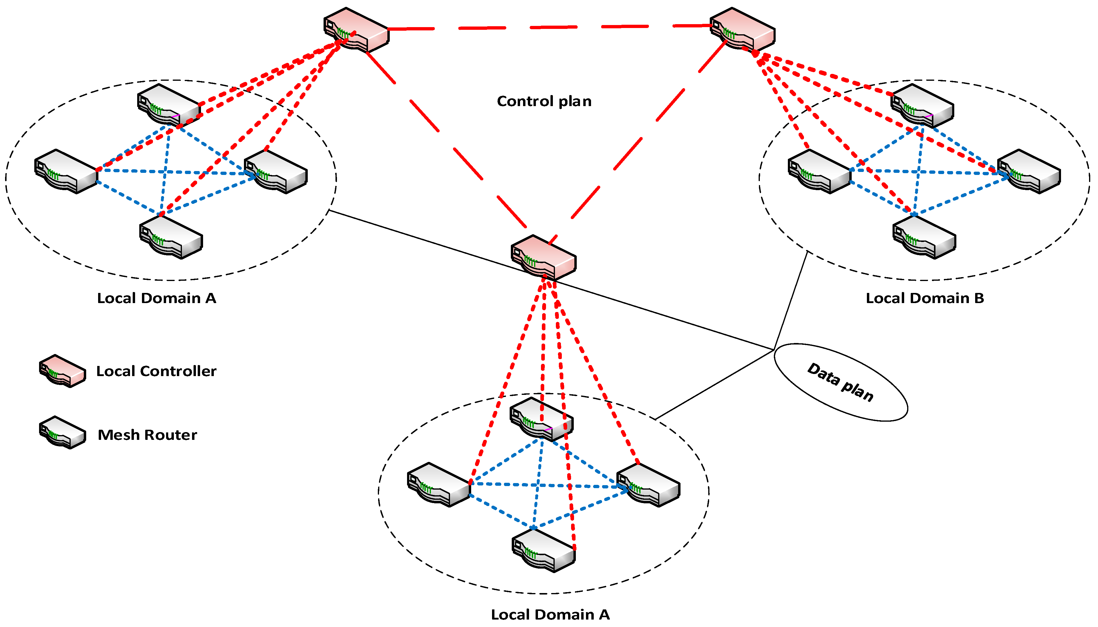
This paper addresses distributed multiple-domain SDWMN, as presented in
Figure 1, which can be deployed for various applications of WMN. Generally, they are decomposed into geographical or administrative interconnected domains, each domain can consist of mesh routers that are equipped with various wireless interface standard technologies, generally any IEEE802.11 standard with at least two frequency bands (one for the control plane and other for the data plane). The Ad-hoc On-Demand Distance Vector Routing (AODV) is used as a QoS routing protocol and delay is used as the main metric, but this work focuses on finding an appropriate architecture that allows using a state-of-art topology discovery and QoS monitoring using Link Layer Discovery Protocol(LLDP) to offer topological and QoS information for any QoS routing protocol that can reside as application on the application plane of the SDN controller in WMN. Surely this is the heterogeneity and distributed nature that WMN calls for to be more robust to failure and adaptable to user requirements. The state-of-the-art distributed solutions of SDWN are not sufficient for WMN scalability, as it needs a fine-grain control plane that depends on an efficient communication system for inter-controller exchange. We propose FD-SDWMN architecture, a Flat Distributed SDWMN. It distributes the control plane among flat distributed SDN controllers; we show how the control plane initializes dynamically to solve the SDN bootstrap problem. After that, the architecture starts providing the main functionalities such as network traffic engineering and disruption and attack survival.
Contrary to currently distributed SDN architectures, WMN based on FD-SDWMN is resilient enough to discriminate links with the best characteristics (bandwidth, latency, packet loss, etc.) for data forwarding. FD-SDWMN is implemented on top of POX [
18] OpenFlow controller, and Advanced Message Queuing Protocol AMQP [
19]. For FD-SDWMN architecture performance evaluation, we present its functionalities on a Mininet-wifi [
20] emulator for SDWN according to a control plane consistency test and two application cases: the topology discovery mechanism for multi-hop networks (the state-of-the-art topology discovery cannot be applied to a multi-hop network such as WMN) and QoS monitoring.
The rest of the paper is organized as follows:
Section 2 describes the FD-SDWMN architecture, it presents the modules and agents that compose the controller.
Section 3 presents the proposed architecture implementation. A detail description of the topology discovery and QoS monitoring is presented in
Section 4,
Section 5 and
Section 6. In
Section 7 this work evaluates the experimental results.
Section 8 concludes the paper and presents our future work.
2. FD-SDWMN Architecture
A centralized controller in SDWMN manages all the switches (mesh routers) of the network (controller–router connection is in a multi-hop). That means each router in the network needs to rely on one controller for forwarding decisions. Thus, for every new flow, each router generates a request to the controller, which responds with appropriate flow entry messages. Obviously, this scenario costs the controller more load and decreases network performance. On the contrary, in FD-SDWMN architecture, the network control has logically divided via network slicing into flat distributed controllers, each of which controls a local domain (controller–router connection is in a single-hop).
2.1. Overall Architecture
FD-SDWMN is a distributed, multi-domain, SDWMN control plane that enables efficient delivery of end-to-end network services. The FD-SDWMN control plane composes of distributed controllers that are in charge of network domains, they communicate with each other to exchange their local information to aggregate a network-wide view for efficient end-to-end management.
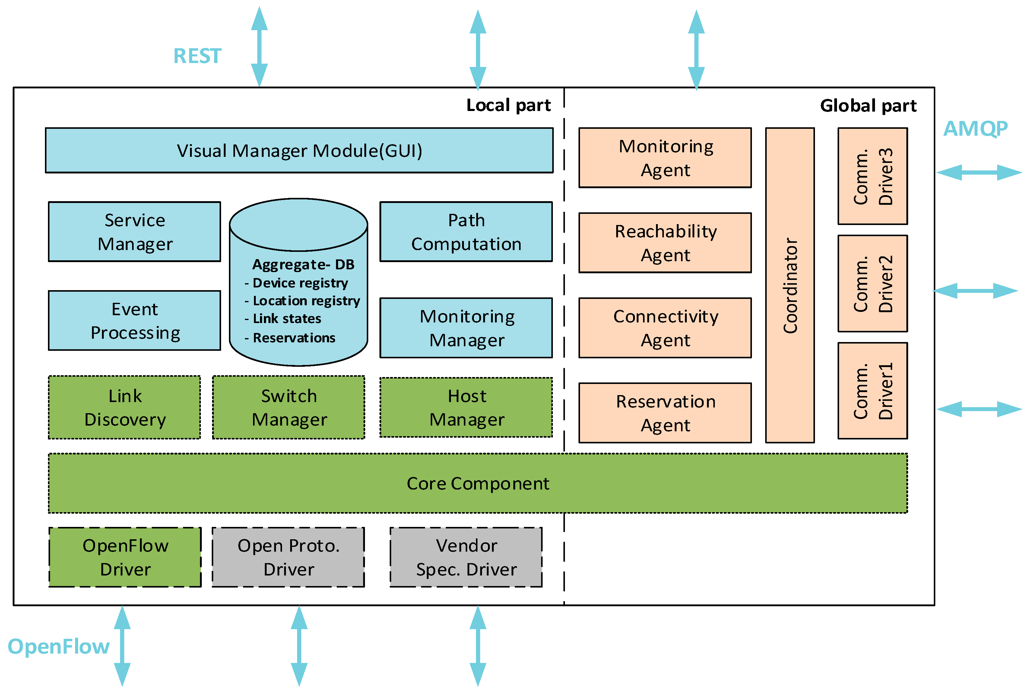
Figure 2 shows that the controller architecture is composed of two parts: the local level, where the main functionalities of a local domain are gathered, and the global level, which aggregates other domains’ control information such as topology state, QoS properties, etc. Also, southbound interfaces are used to push forwarding policies to data plane elements and gather their status. Finally, the northbound interfaces provide controllers with applications’ management policies and requirements.
Multiple modules compose the controller functionalities, they are managed (start, stop, update and communicate) by the core component. FD-SDWMN architecture leverages from the existing SDN controller’s modules, such as the OpenFlow driver for OpenFlow protocol implementation, router and host managers for keeping track of network elements and link discovery that implements LLDP (Link Layer Discovery Protocol) for topology discovery. Furthermore, new modules are developed to enhance architecture functionality as displayed in
Figure 2. Controllers must communicate with each other to gather and accumulate overall network status information. In order to accomplish this task, each controller uses two essential parts: (i) a coordinator module discovers neighboring domain controllers to establish and maintain a reliable and secure distributed publish/subscribe channel. Moreover, (ii) different agents that exchange needed information among controllers via this channel.
2.2. Local Functionalities
The local modules in charge of network topology discovery, QoS monitoring, etc., manage flow prioritization, so according to network parameters the controller computes routes for the priority flow. Also, the modules react to network state (link broken, high latency, bandwidth degradation, etc.) dynamically by stopping and/or redirecting traffic according to its criticality. This work is different from our previous work [
21] that presented a hierarchical architecture.
The aggregated-DB: is a central database in which a controller stores its local domain and other domains knowledge on topology, QoS monitoring and ongoing data flow. Other modules and agents use this information to reach the ultimate goals, i.e., taking suitable action on flows within a local domain and entire network.
The QoS monitoring module: gathers QoS information such as bandwidth, delay, jitter and packet loss of domain switches and links in between using customized LLDP packets, and other domains’ QoS information is aggregated.
The path computation module: computing routes from source to destination in the local domain and entire network using the Dijkstra algorithm taking into account QoS metrics of links in between. This module consults the aggregated-DB for network topology and QoS monitoring information.
The service manager module: supports end-to-end provisioning by receiving requests from northbound APIs for efficient network SLA (Service Level Agreement) management. It verifies SLA feasibility and respect for consulting other modules.
The virtual manager module: resides on top of the other modules. It offers a Graphical User Interface (GUI) through network virtualization to interact with other modules. It gathers information from many down modules and displays them to the network operator. Also, it provides them with essential network parameters such as flow priorities, new routes, etc.
The coordinator: this module establishes a control channel between controllers. It manages status information that frequently exchanges (such as link state, host presence) and requests between controllers. Hence, this communication channel should be reliable to guarantee the messaging process. For delivery security and reliability, AMQP is used for Coordinator implementation because it ensures Reliability of message deliveries, Rapid and ensured delivery of messages and Message acknowledgements.
2.3. Global Functionality
To collect and maintain a global network view in each controller supporting network efficient QoS routing and reservation functionalities, the following agents are defined and implemented.
The connectivity agent: is in charge of maintaining peering links between the controllers. The work of this agent is based on event-driven fashion, it only sends information if a new controller is discovered or existing peering link between controllers is changed. This information is grouped and maintained into the aggregated-DB, and like other information it is accumulated by all neighboring connectivity agents. Eventually, the connectivity information is used to make global routing decisions by the path computation module.
The monitoring agent: periodically receives information (QoS properties) about available links and their capabilities, in order to support traffic transmission among network domains.
The Reachability agent: advertises the hosts presence on local domain margins so they become reachable. It offers a roadmap between domain switches and hosts.
The reservation agent: is concerned with overall network flow setup, e.g., link teardown, and updates requests and application requirements such as QoS. It is like the Resource Reservation Protocol (RSVP). Each controller handles these requests by the service manager, and the reservation agents of these controllers along the path communicate to create and maintain the needed path.
In order to achieve FD-SDWMN control plane consistency, the agents publish and consume messages managing the required topics. The aggregated information that concerns reachability (reachable hosts listed in the network), connectivity (a list of peering controllers) and monitoring (peering transit paths status, in terms of QoS metrics, etc.). This way, a controller can build a view of the entire network. Thus, it has the capabilities to perform path reservation, routing and manage SLAs.
3. Architecture Implementation
We implemented FD-SDWMN architecture on top of the POX, an open source controller. There were some modules taken from POX’s Python code with a little modification, other modules were developed in Python to manage controllers’ communication. The agents located in each controller notify link states, device location and requests of path reservation using this control channel.
3.1. Coordinator Implementation
The coordinator is implemented as any other POX application. It receives Packet-In messages from the Core module after subscription, sends its Packet-Out messages, reads and writes information from/to the aggregated-DB and at startup it views the POX controller configuration file. For coordinator operation, there are configurations parameters which should determine: agents_list, messaging_server_type and messaging_server_listening_port. Also, other optional parameters can be specified. An agent is a small class that manages inter-domain exchanges to/from a module to handle intra-domain communication. Coordinator activates a specific agent from the agents_list by specifying the port that it reaches by the messaging_server_listening_port. Moreover, from the messaging_server_type parameter, the coordinator determines the messaging driver that it uses, for current implementation the RabbitMQ driver [
21] is used to implement the federation mode of AMQP, but the FD-SDWMN architecture allows the use of other AMQP implementations such as Active MQ.
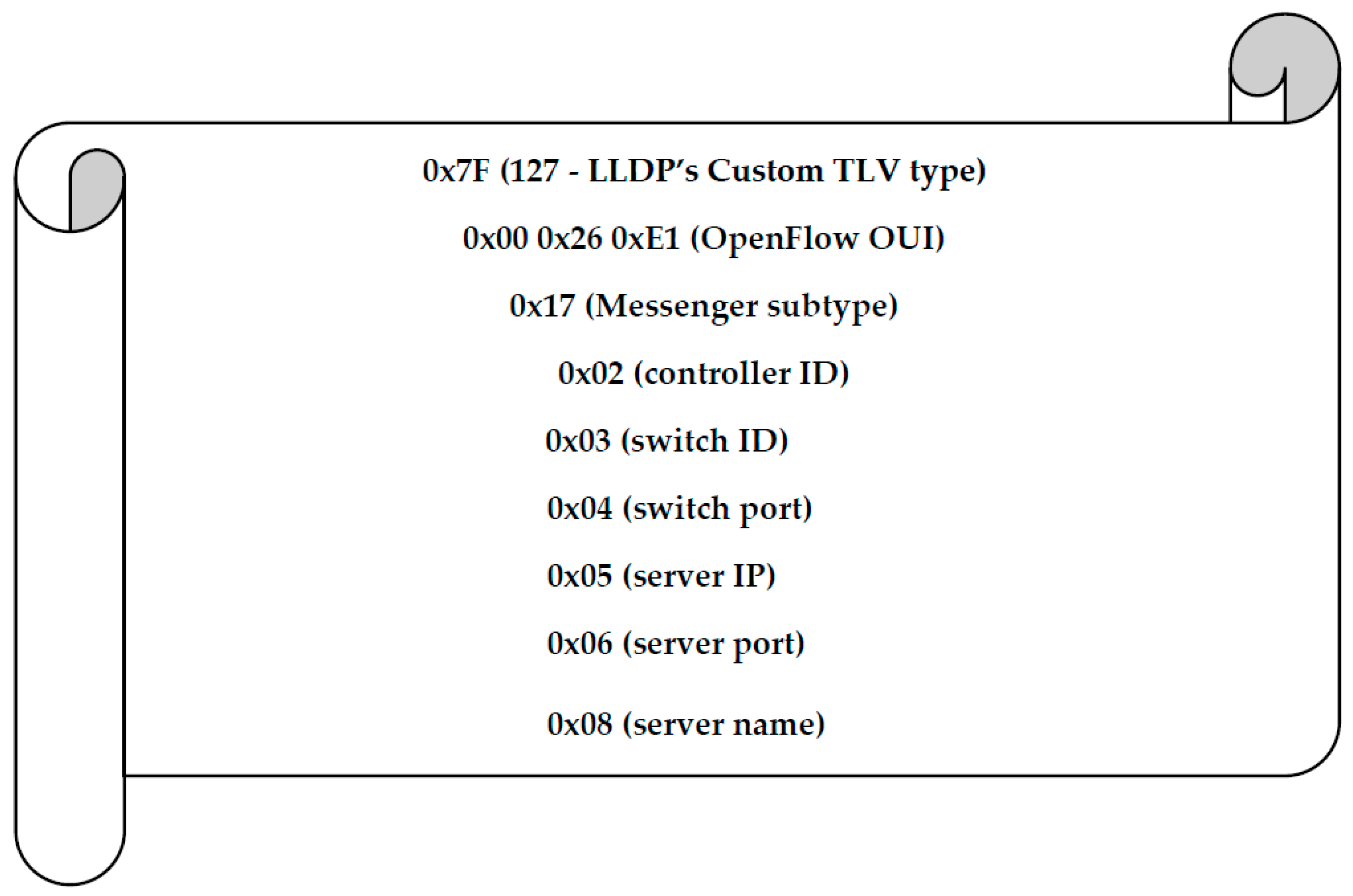
The coordinator implements an extended LLDP (Link Layer Discovery Protocol) version, which is called Coordinator-LLDP (C-LLDP) that is used in discovery functionality. The C-LLDP message contains an OpenFlow option added to the regular LLDP message. Moreover, IEEE has allocated the Organizationally Unique Identifier (OUI) to OpenFlow. The coordinator sends these messages announcing controller existence in order to discover other domains’ controllers. When it receives a reply toa discovery message, it establishes a connection via AMQP to its peer in that controller and stops sending discovery messages. Otherwise, the coordinator continues sending discovery messages periodically. A C-LLDP message—as shown in
Figure 3—contains the required information to reach a controller.
The coordinator offers a communication channel (publish/subscribe) for inter-domain exchanges. It is essential the operation is done via two particular topics: C_ID.*.* topic, where C_ID is a controller identifier. Via this topic, other controllers can directly send messages to this controller. For instance, this is used for a local domain topology discovery update. The other topic is general.*.*, which enables a controller to communicate to all other controllers in the network, such as when a controller decides to leave its domain.
The coordinator communicates with AMQP implementation via drivers. An AMPQ driver should support a set of functions:
- (1)
Subscribe (topic)/unsubscribe (topic): to add and remove a topic to/from the topic list.
- (2)
Send (topic, message): send to a particular topic a specific message.
- (3)
Pair (C_ID) and unPair (C_ID): controller function to create a control channel to another controller and the opposite function is to remove this channel when a controller fails and is not able to receive information from neighbors.
The coordinator also maintains a controller existence by sending periodic Keep-Alive messages. In the case that three contiguous Keep-Alive messages have no response, a controller infers that its neighbor controller has failed and it triggers a mitigate procedure for this failure. The coordinator application is flexible enough for an extension without altering the main classes of POX. Developers can provide a new driver for the implementation of AMQP to extend the coordinator class, or by adding a new agent function.
3.2. Agents Implementation
Agents use the coordinator to exchange information between distributed controllers among neighboring domains. In this architecture, four agents were developed: Reachability, Connectivity, Monitoring and Reservation (see
Section 2.3). They publish on particular topics, e.g., monitoring.C_ID.bandwidth.2s where the monitoring agent at a controller that is identified by C_ID advertises the remaining bandwidth it can offer for traffic transmission. Any received information from neighboring domains’ agents is stored in the aggregated-DB of the local agent. Then this information is used by the modules of the local controller to take a decision on flows over the network.
For end-to-end provisioning, the reservation agents implement a mechanism like RSVP reservation protocol, they exchange reservation requests responding to flow descriptors. The development of the coordinator and its assistants (drivers, agents, etc.) adds extra lines of code and their operation consumes extra memory of the POX controller.
4. Topology Discovery
Topology discovery is critical for the efficient operation of SDN-based network services and applications, which need to have updated information that describes the network state. An SDN controller is responsible for offering this information using an efficient and reliable approach. There is no standard topology discovery of OpenFlow devices. However, most of the current SDN controller systems use the same approach implemented by the original SDN controller (i.e., NOX controller) [
22]. This mechanism, named OpenFlow Discovery Protocol (OFDP) [
23], is used as a topology discovery de facto scheme. OFDP leverages the Link Layer Discovery Protocol (LLDP) [
24], which allows switches in LAN (IEEE 802 Local Area Network) to advertise their capabilities to each other.
Figure 4 depicts a simple scenario for topology discovery, the process detailed in [
22]. Although the OFDP mechanism was adopted by the majority of the current controller platforms, the controller suffers from the number of messages loaded during the process. For one cycle of topology discovery, the controller sends a Packet-Out message per every active port of the switches and receives two Packet-In messages for each of links between them. Since topology discovery is a periodical process, the OFDP mechanism affects controller performance because the number of packets in/out to/from a controller is dependent on the number of network switches and their active ports. For that, the heavy load of the topology discovery process in a controller is increased according to the network scale.
However, due to the operation mechanism of the LLDP protocol, it is not able to discover multi-hop links between switches in pure or hybrid OpenFlow networks. Therefore, there are two main problems of the current topology discovery approach, one is the controller overload and the other is this approach only works in single-hop networks. To solve the first problem i.e., controller overload, the authors in [
22] proposed a new version of OFDP. They called it OpenFlow Discovery Protocol version 2 (OFDPv2). It reduces the number of Packet-Out messages to one message per switch, instead of one per each active port of the switch. The work proved that the modified version is identical in discovery functionality to the original version. Furthermore, it achieves the aim with a noticeable reduction messages exchanged and reduces the discovery induced CPU load of the controller by around 45% without any consequent delay compared to OFDP.
To solve the second problem, i.e., the inability of applying OFDP or even OFDPv2 to multi-hop networks, because both OFDP and OFDPv2 leverage LLDP packets as mentioned above, and LLDP packets are a “bridge-filtered multicast address”, so they are a single hop and not forwarded across switches [
22]. In hybrid networks where there are one or more traditional switches (do not support OpenFlow) between OpenFlow switches, they process the LLDP packets and drop them. Therefore, the controller should use a combination of LLDP and BDDP (Broadcast Domain Discovery Protocol) to discover indirect links between OpenFlow switches ports in the same broadcast domain [
25]. However, this work does not present any solution for pure OF switches in multi-hop networks.
Adapting the OFDP topology discovery approach to SDN based wireless multi-hop networks is a challenge. Due to its limitations in collecting wireless node and link characteristics, such as node related attributes: localization and QoS properties, and link nature: not point-to-point and not fixed connection capabilities like wired links, [
26] proposed “A Generic and Configurable Topology Discovery” to analyze the general topology discovery representation required by SDN applications and how the SDN controllers offer it.
We consider our work as a direct adaptation of the state-of-the-art topology discovery in wireless multi-hop networks.
4.1. Aggregated Topology Discovery Mechanism
Among the FD-SDWMN architecture, the aggregated topology discovery mechanism can have the ability to apply the topology discovery protocol (OFDP) in multi-hop networks such as a wireless mesh network. The mechanism is based on OFDPv2 and benefited from the multi-hop control channel breaking into a single-hop by dividing the process into two phases: local domain topology discovery and global network topology aggregation, the proposed mechanism reduces the heavy load of topology discovery in the controller.
4.1.1. A Local Domain Topology Discovery
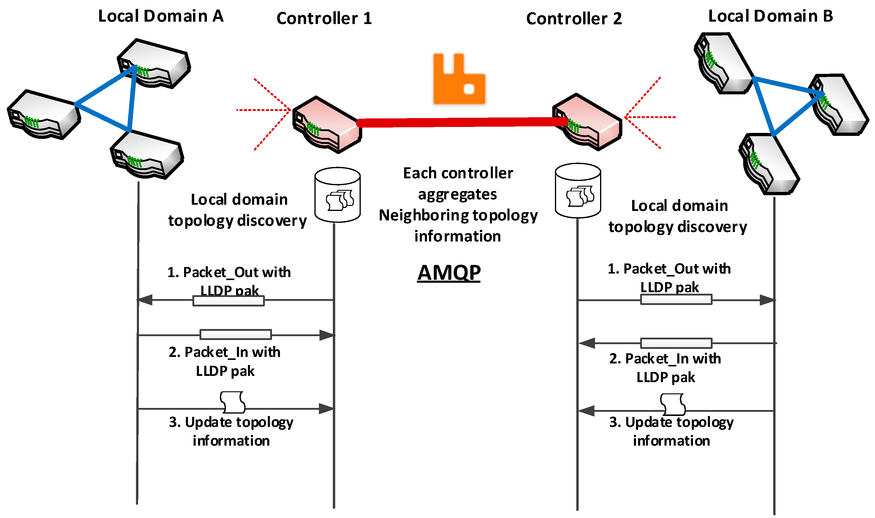
Each controller starts topology discovery service using its Link discovery module to discover local domains’ nodes. Precisely, in this process, the local controller is concerned with link discovery, and it does not need to rediscover the domain nodes (switches) since they already have initiated a connection to the controller. A controller sends an individual Packet-Out, each of which contains an LLDP packet, with a rule to send the specific packet out on the corresponding interface. Then via the Packet-In message, the LLDP packets send to the controller obeying to the pre-installed rule that says, “Forward any received LLDP packet from any interface except CONTROLLER interface to the controller”. The process is repeated for every router in the domain, to discover active links between them. The entire domain topology discovery process is periodically performed every 5 s, the default interval size of the NOX controller. Ultimately, each controller maintains up-to-date local domain topology information in its aggregated-DB, and the connectivity agents exchange other domains’ topology information. To this end, this work proposes an initial appropriate SDN based architecture, additional issues will be addressed such as channel sharing and propagation modes later.
4.1.2. Entire Network Topology Aggregation
Using the coordinator module each local controller can discover other neighboring domain’s controllers and maintain a control channel to them, then the connectivity agents can exchange and aggregate topology discovery information of the surrounding domain in each controller and aggregate this information of entire network topology in its aggregated-DB. By using this hierarchically aggregated mechanism over FD-SDWMN architecture, the heavy topology discovery computation burden on a controller can reduce and the slow convergence time problem of the distributed nodes of high scale WMNs can be addressed.
Figure 5 depicts the control message flow of the aggregated topology discovery mechanism.
5. QoS Monitoring
Quality of service of network forwarding devices is particularly crucial for real-time applications like video streaming. The current SDN topology discovery service does not monitor or collect the QoS of underlying network elements, in spite of the fact that it is based on the LLDP protocol, which can collect QoS properties [
27]. As shown in
Figure 6a, additional to the mandatory TLVs (Type/Length/Value, i.e., key-value pair with length information) fields that are used in topology discovery, LLDP has optional Type Length fields that can be customized to discover other features such as QoS properties. In [
27] four optional fields were identified to carry bandwidth, delay, jitter and packet loss, with an 8 byte size of each property as shown in
Figure 6b. Therefore, a customized LLDP packet for QoS collection is longer than the original LLDP packet by 38 bytes. Since the aggregated mechanism allowed applying LLDP-based topology discovery on FD-SDWMN, it also can monitor and collect QoS.
6. The Controller Traffic Overhead
Controller load and performance is a critical factor of SDN scalability. Since the topology discovery service in the SDN controller is running periodically, it is important to calculate and know the load this service exploits the controller. As was mentioned above, the FD-SDWMN architecture offers the appropriate environment for applying topology discovery based on LDDP. Due to the current topology discovery mechanism, the controller load depends on the number of Packet-Out messages that the controller should send addition to the number of Packet-In messages received. Discovering a local domain topology is not different from the state-of-the-art mechanism. In every discovery cycle, the amount of received LDDP Packet-In messages by a controller depends on the number of nodes a local domain has. Actually, it is twice the amount of active inter-router links within the domain, a packet per each link direction. On the other hand, the total amount of LLDP Packet-Out () messages sent by the controller every cycle is equal to the total number of switches.
With being the number of switches the domain has and the number of inter-switch links, similarly to a single controller single-hop architecture, the number of messages in/out of the controller can be expressed as follows:
For the current mechanism (OFDPv2):
A significant reduction of the LLDP Packet-In and Packet-Out message numbers for the entire network topology discovery can be achieved in every controller of the FD-SDWMN architecture when discovering entire network topology using the aggregated topology discovery mechanism. The controller load can be calculated in two stages: firstly, when discovering links between local domain switches, depending on the number of domain members. Secondly, the load of aggregating the other neighbors’ local domain’s topology information as an event-driven message for each domain using connectivity agents of AMQP, depending on the performance of the AMQP system.
With
being the number of local domain switches,
the number of inter-local domain links,
the number of messages exchanged by connectivity agents, the number of messages in/out of the controller can be expressed as follows:
Together with the FD-SDWMN architecture, this adapts a suitable environment to apply current topology discovery in WMN. Moreover, it reduces the load of the controller. It reduces the number of the direct topology discovery message i.e., Packet-In and Packet-Out messages, and after AMQP starts, the connectivity agents send the topological information messages on-demand. Then the load calculation of direct discovery messages in the controller depends only on the number of the switches of the domain it controls instead of the entire network’s switches, in addition to the load of messages exchanged by the connectivity agents between a particular controller and peering controllers that are distributed over WMN.
Since the number of switches and their ports is the key parameter that impacts the controller load in OFDP [
22], the aggregated mechanism can be compared with OFDPv2 to see how much it has improved the topology discovery load on the controller. We calculate
the gained efficiency in terms of reduction of the number of direct Packet-In and Packet-Out messages, for mesh network with
switches,
local domain switches and
interface for a router as follows:
Notice that the reduction gained will be higher for WMNs with a large number of total switches according to Equation (6), but the number of nodes within a same local domain that is sharing the same broadcast must be addressed. We verified this with experiments using Packet-Out because its calculation only depends on the number of mesh routers and local controllers.
On the other hand, notice that customizing and extending the LLDP packet for QoS monitoring despite it extends LLDP packet size, but the traffic flow is slightly different as in the topology discovery service.
7. Evaluation
This section presents how we assessed FD-SDWMN capabilities. The addition of main functions to this architecture such as QoS routing and reservation, aims to be resilient to disruptions in the control plane (controller failure, inter-controller communication failure) or the data plane (inter-switch link failure). Thus, we present a control plane adaptation test and two use cases to evaluate FD-SDWMN features.
7.1. Experimental Setup
For experimental evaluation, we used Mininet-wifi, the Software Defined Wireless Network emulator, which creates a network of virtual SDN switches (routers), stations (hosts) and wireless channels (links). We exactly used Open vSwitch [
28], which is a software-based virtual SDN switch with OpenFlow support, to create mesh routers that are equipped with two non-overlapped interfaces. Mininet-wifi was run in VirtualBox as virtualization software, and Linux used as the hosting operating system. As we mentioned previously, the POX controller was used as our experimental SDN controller platform and the programming coding to implement the proposed architecture was implemented in python. All the software used for experiment prototype implementation are summarized in
Table 1.
All experiments were performed on a Dell Laptop (Inspiron15 5000 Series) with an i7-8550U Intel CPU, running at 1.8 GHz, with 12 GB DDR4 2400 MHz RAM.
7.2. Control Plane Adaptation
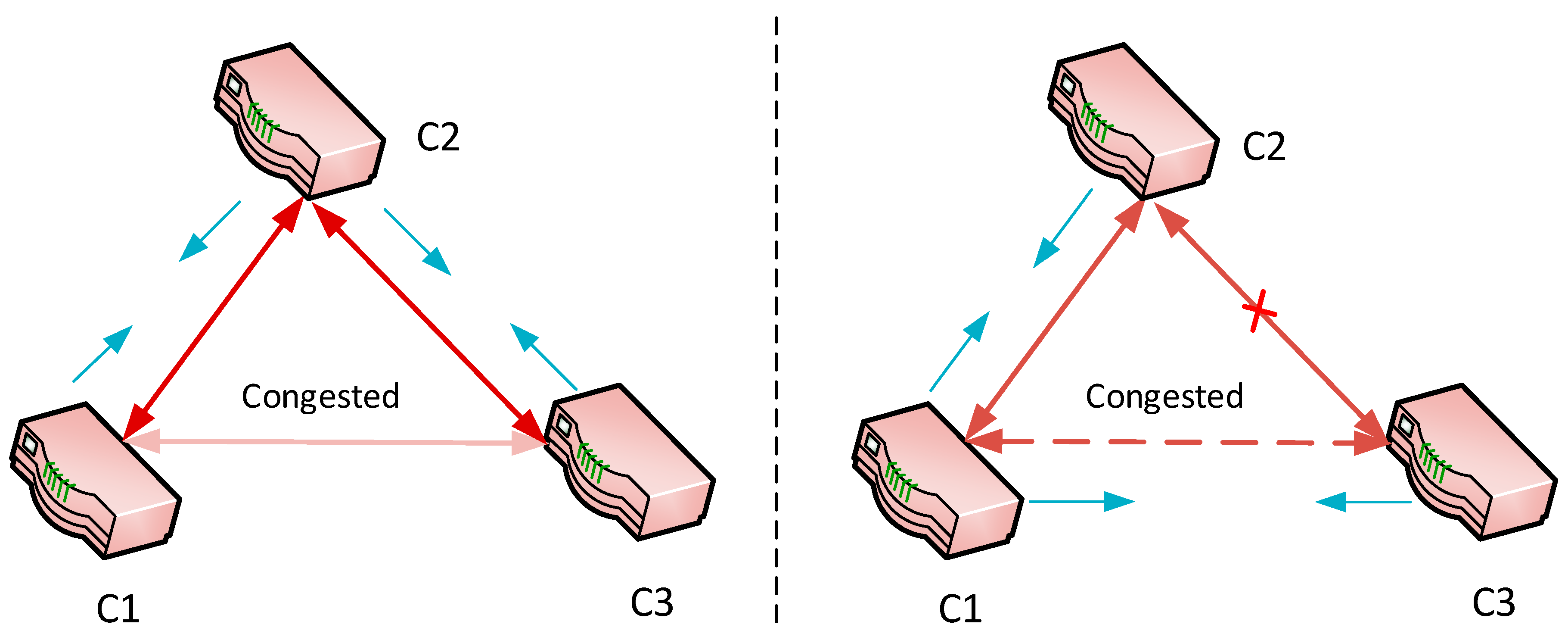
This scenario shows how FD-SDWMN’s controllers exchange control information and control self-adaptation to the network states. To mitigate any congestion in the control messages, exchange links between controllers’ agents offload traffic of a weak direct control connection (via a dedicated control channel (out-of-band)), by identifying alternative routes or reducing the control messages frequency on it if no alternative route. For instance, the monitoring agents usually send information every 3 s, and this period changes to 10 s in weak links. Also, connectivity and reachability agents can send their information via alternative routes. However, they are event-driven agents contrary to the monitoring agent.
Upon control plane bootstrapping and controller discovery, the C1 and C2 are connected to C3 as depicted in
Figure 7. In this scenario, the control-link between C1 and C2 is congested (its latency = 50 ms). Thus, the monitoring agent is relaying control messages between C1 and C2 via C3 to offload the congested link.
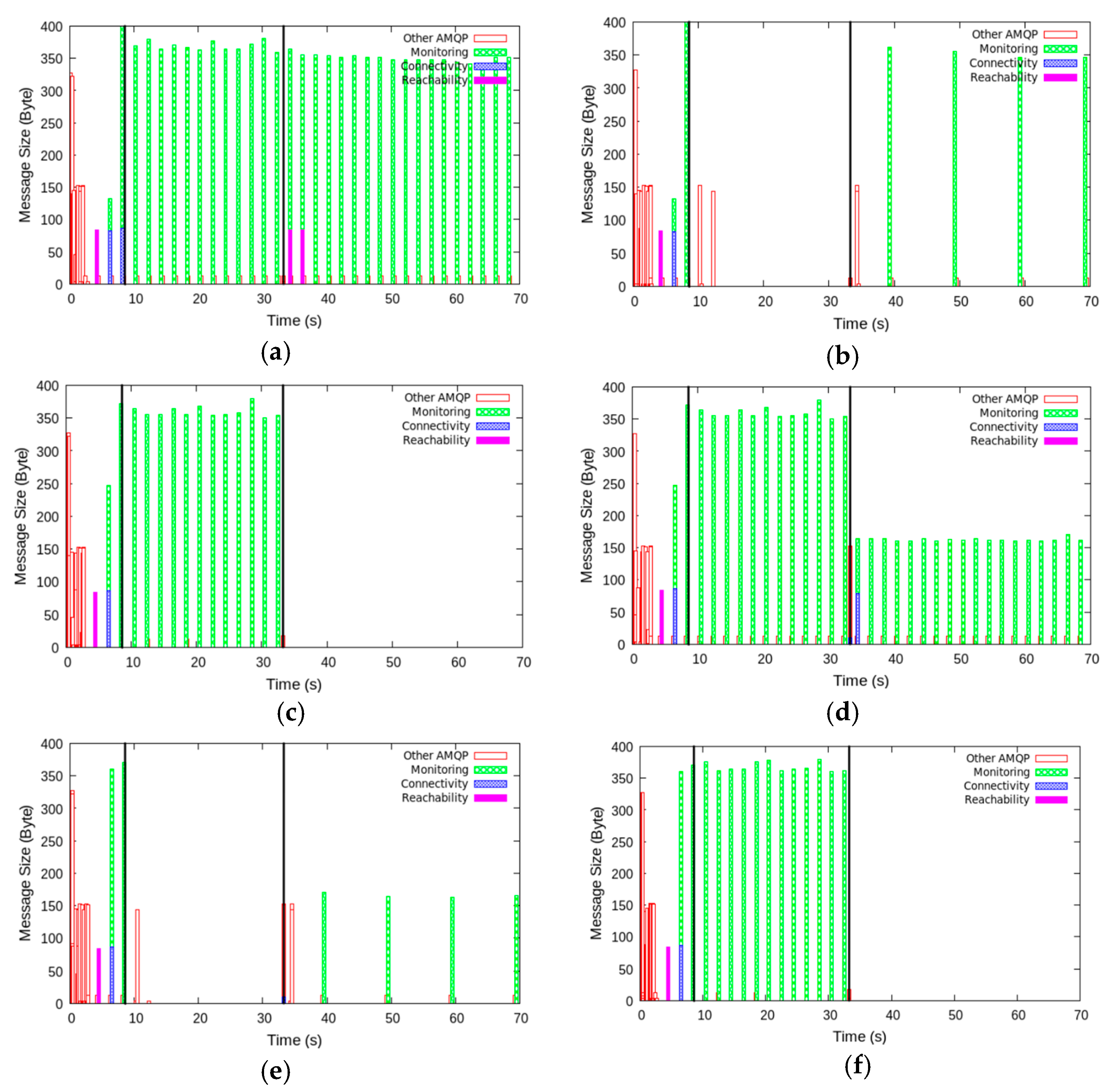
Figure 8 presents the conducted evaluation to show FD-SDWMN control plane adaptation with network conditions, e.g., the C2↔C3 link failure. The figures show the utilization of the link in both directions, left after C3 discovers C1 and C2 and the AMQP system starts exchanging messages between them. The TCP payload of received packets splits into three stages:
Local controller discovery: takes the first 9 s where controllers exchange their capabilities to advertise themselves. The AMPQ communication system is active during this period because the brokers should establish the control channel and subscribe to available topics. During this stage, the monitoring process has already started but not adapted to the weak link yet.
Monitoring adaptation: after the end of the previous stage until t = 33 s. In this period the weak link is discovered by monitoring agents and they start adaptation behavior. As observed in
Figure 8a,d, the monitoring stopped from t = 10 s because the C1↔C3 is congested (weak), at the time in
Figure 8b,e, the monitoring traffic is increased over the C1↔C2 and C2↔C3 links as in
Figure 8b,c,e,f.
Failure recovery: starts right after the alternative link C2↔C3 is cut at t = 33. Thus, the monitoring information is forwarded via the congested link C1↔C3 but in adapted frequency, as in
Figure 8b.
7.3. Aggregated Topology Discovery
We implemented the aggregated topology discovery mechanism after performing the necessary modification on the POX Link discovery module (discovery.py) in python to apply the enhanced version of OFDP (i.e., OFDPv2). Extensive tests were performed on the architecture to establish OFDPv2 functionality. As expected, it was implemented in WMN as one of the multi-hop networks. The main goal of our evaluation is to prove that using the FD-SDWMN architecture allows using the same approach of the current SDN topology discovery, as in
Section 4.1, there is no difference between the current mechanism and the first phase of the aggregated mechanism in regard to the topology discovery of the local domains. Our focus is on the entire network topology discovery load produced by LLDP packets that the controller sends and receives. The advantage of the aggregated mechanism in every controller is to gather the topology information from other controllers by distributed connectivity agents of AMQP in dynamic event-driven communication.
We created a wireless mesh network topology of 105 switches, and five controllers, each of them controlling a local domain of 25 switches ( = 25). We observed and collected the statistics of each controller outflow (Packet-Out) per topology discovery cycle. The experiment wasreplicated 10 times with similar outcomes as expected. If we take a particular controller, we find it sends five Packet-Out messages to discover its local domain switches. Then the controller saves this information in its aggregated-DB and sends requests via connectivity agent to collect neighboring domains’ topology information, and it also replies to any other controllers’ requests. So, we can calculate the controller load if we estimate the number of messages produced by AQMP but this is out of the scope of this paper. Contrarily, if we suppose one controller manages the entire network ( = 125), we can calculate the number of Packet-Out = 125 messages according to Equation (2). Also, we can calculate efficiency gain of the aggregated mechanism over OFDPv2 as in Equation (6). As we see the experimental results corresponding to Equations (2) and (4) and the parameters of the topology.
The reduction of Packet-Out messages results in a direct enhancement of controller CPU performance. Then the aggregated mechanism which achieves a reduction in the number of both Packet-In and Packet-Out messages instead of only reduction of Packet-In in OFDPv2, will positively impact the controller CPU load. However, such a reduction of the CPU load of the FD-SDWMN architecture is a significant improvement compared to the state-of-the-art. There are additional benefits of the aggregated mechanism, we mention some of them here without evaluation, such as the traffic reduction on a controller-router channel by reducing Packet-In and Packet-Out message flow, particularly in SDN architectures that adopt an in-band controller.
7.4. QoS Monitoring Scenario
Here, we have tested the capability of QoS monitoring over FD-SDWMN.
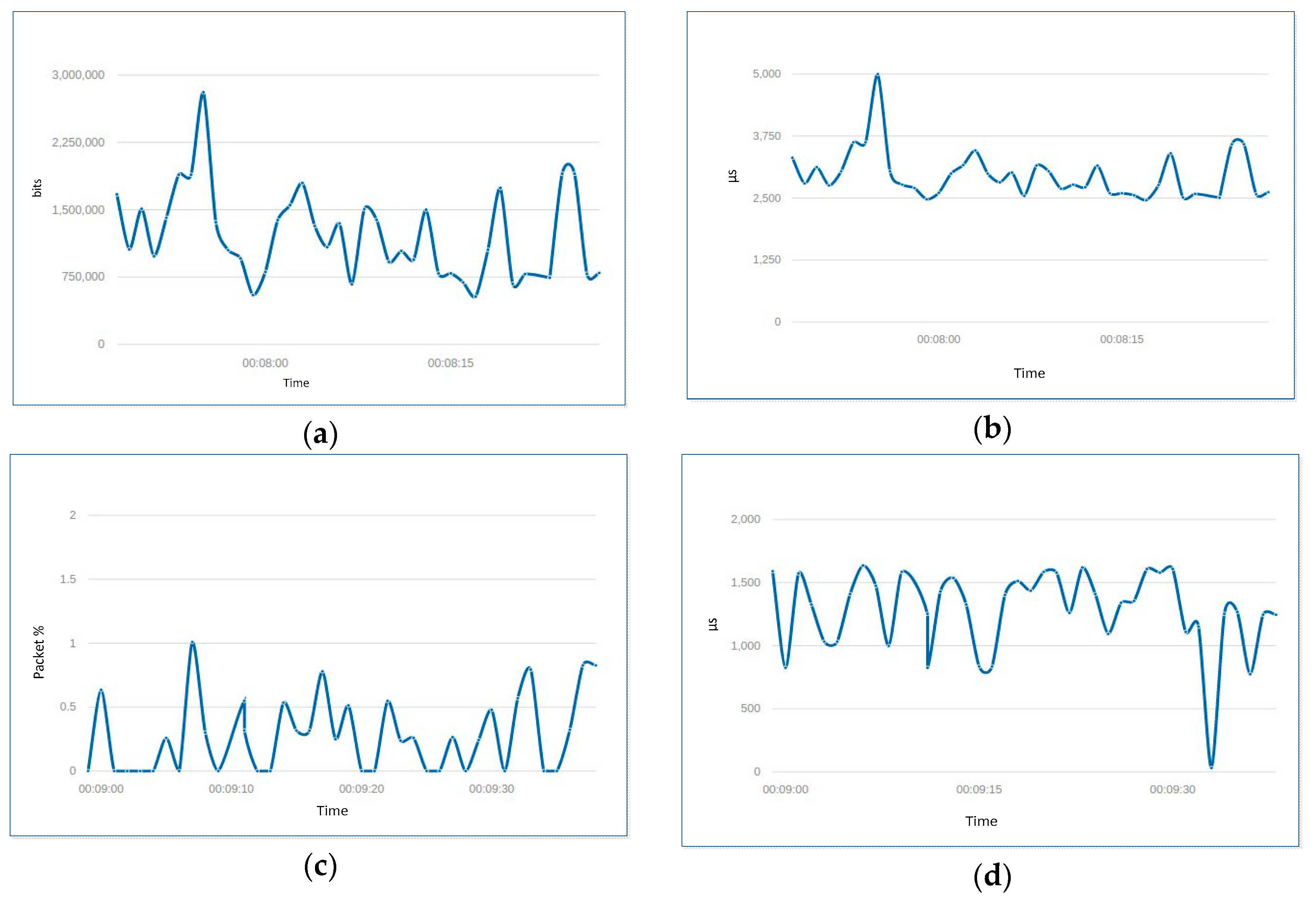
Figure 9 depicts a simple scenario of application of video streaming over two local domain’s architecture, where A.H1 is the server that streams a video (size = 400 MB and length = 10 min) to the client B.H2. Initially, QoS properties of the switches’ ports were set as follows: 5 Mbit for bandwidth and 2500 µs for the delay. During the video streaming, QoS properties (bandwidth, delay, jitter and packet loss) were changing due to the consumption of resources. The properties gathered by monitoring agent at controller A proves that the aggregated mechanism can also effectively monitor QoS changing over LLDP.
Figure 10 shows fluctuations curves (QoS over LLDP frontend GUI snapshots) of the QoS properties changes. The
Figure 10a–d present the real-time statistics of QoS properties bandwidth, delay, jitter and packet loss, respectively, of interface B.S4-eth2 as instance (i.e., the second Ethernet interface eth2 of router s4 in the local domain B) monitoring from the controller B, then the controller A controller aggregates this information in its aggregated-DB, and the monitoring process continues for all switch interfaces of the domain. Duration of 15 s was used as the default interval of LLDP.
Despite QoS monitoring over LLDP adding extra bytes to customize the optional TLVs of LLDP packets for QoS properties collecting, it has no significant difference in network traffic compared to that caused by original packets such as those used for topology discovery. To evaluate this increase of network traffic, we compared between pure LLDP packets (used for topology discovery) and customized LLDP packets (used for QoS monitoring). Both scenarios run separately during video streaming in the topology stated in
Figure 9. Network traffic was captured using Wireshark, to measure the total network traffic and only LLDP packets (packet filter set to “LLDP”) for 15 min. The evaluation results showed slightly different network traffic caused by QoS monitoring. The results showed that the percentage of QoS monitoring is about 80%of the total packet flow compared to 77% for topology discovery. This proves that QoS monitoring over LLDP does not cause network traffic performance deterioration,
Table 2 shows the evolution results.
8. Conclusions
In this paper, we have proposed FD-SDWMN, a Flat Distributed Software Defined Wireless Mesh Network multi-domain architecture. Its organization relies on a peering domain; each domain is managed by a local controller. The controllers establish a lightweight manageable control channel in between domains and are for agents that developed to share and aggregate network-wide information in order to enhance end-to-end network services. The distribution of the controllers surrounding a considerable number of mesh devices that cover large geographical areas supports WMN network scalability, and SDN controllers need to be closer network edges for collecting and monitoring network status. We demonstrated how FD-SDWMN works and resiliently responds and survives when network disruption occurs. FD-SDWMN is a suitable architecture for multi-hop networks such as WMN in order to benefit from SDN controller services, which are only applicable for single-hop networks, e.g., topology discovery and QoS monitoring. We have implemented FD-SDWMN architecture on top of the POX OpenFlow controller and the AMQP protocol. The architecture functionalities were evaluated according to control plane adaptation test and two use cases: aggregated topology discovery and QoS monitoring mechanisms. As a future work, we decided to enrich FD-SDWMN architecture with additional self-healing and resilient recovery mechanisms to be more reliable for supporting QoS routing for video streaming over WMN.


