CKMI: Comprehensive Key Management Infrastructure Design for Industrial Automation and Control Systems


1
Department of Computer Technology, Dayananda Sagar University, Bangalore, Karnataka 560078, India
2
School of Computing and Information Sciences, Florida International University, Miami, FL 33199, USA
3
Department of Computer Science and Engineering, Siddaganga Institute of Technology, Tumkur, Karnataka 572103, India
*
Authors to whom correspondence should be addressed.
†
These authors contributed equally to this work.
Future Internet 2019, 11(6), 126; https://doi.org/10.3390/fi11060126
Submission received: 2 April 2019
/
Revised: 15 May 2019
/
Accepted: 27 May 2019
/
Published: 4 June 2019
(This article belongs to the Special Issue Next-Generation Public-Key Infrastructures)
Abstract
:Industrial Automation and Control Systems (IACS) are broadly utilized in critical infrastructures for monitoring and controlling the industrial processes remotely. The real-time transmissions in such systems provoke security breaches. Many security breaches have been reported impacting society severely. Hence, it is essential to achieve secure communication between the devices for creating a secure environment. For this to be effective, the keys used for secure communication must be protected against unauthorized disclosure, misuse, alteration or loss, which can be taken care of by a Key Management Infrastructure. In this paper, by considering the generic industrial automation network, a comprehensive key management infrastructure (CKMI) is designed for IACS. To design such an infrastructure, the proposed scheme employs ECDH, matrix method, and polynomial crypto mechanisms. The proposed design handles all the standard key management operations, viz. key generation, device registration, key establishment, key storage, device addition, key revocation, key update, key recovery, key archival, and key de-registration and destruction. The design supports secure communication between the same and different levels of IACS devices. The proposed design can be applied for major industrial automation networks to handle the key management operations. The performance analysis and implementation results highlight the benefits of the proposed design.
1. Introduction
Critical infrastructures are the primary needs of the society. To reduce the complexity in the operations of critical infrastructures, there is a need for simple and efficient process supporting remote monitoring and control of various activities, which can be achieved through automation. Industrial automation helps to automate the operations involved in the technical processes with much less human intervention. Industrial automation and control systems ensure accuracy, flexibility, and reliability in managing industrial processes. Presently, the critical infrastructures such as electric power networks, water appropriation plants, paper and mash industry, oil refineries and fabricating plants are the major examples in which the IACS is playing a critical role [1].
Industrial automation systems are hierarchical in structure. Different components at different levels are used to monitor and control the industrial plants. One such IACS model is shown in Figure 1. The model consists of three levels: field network, control network and plant network. IACS includes the various devices in the industrial plant to perform automation and monitor the industrial facilities. The resource constraints at different levels of the automation system are different. The devices at each level differ in their capacities such as storage, communication, computation, accessibility, power requirement and latency. The various types of devices situated at different levels are as follows:
- Field level network: It includes sensors (optical, magnetic, thermal, etc.), IEDs and actuators (magnetic valves, motor stats, power switches, etc.). Sensors help to monitor leakages in the pipes, to monitor pipe pressure, to monitor the flow rate, to check boilers temperature, etc. [2]. They help the IACS operator to maintain the functionality of the system in normal condition. Hence, they are called as the eyes and ears of industrial control systems.
- Control level network: It includes PLCs, RTUs, ICS servers and controllers such as AC800M, AC800C, etc. RTUs are field level equipment used for data acquisition from sensor devices and actuators. They are located remotely with respect to the control center. PLC functions similar to RTU. RTUs are normally used for collecting data from a large geographical areas, whereas PLCs are used in the case of local control.
- Plant level network: It includes connectivity server, aspect server, application server, monitoring stations, domain controller, OPC operator workplaces, third-party application servers, ICS users, engineering and monitoring stations and other servers. The industrial network can be associated with the web for remote observing via firewall and VPN.
For the last few years, industrial control systems security is a hot topic in the research community. The catch of malicious activities (Stuxnet [3], Duqu, Flame, Havex [4,5], etc.) and their massive damage on the real-time systems enforce the plant owners and the nations to consider the security for industrial automation systems as a high priority issue [6]. The attacks occurred on SCADA systems are discussed in [4].
The communications in the IACS are real-time in nature. Based on the data obtained from the field network, the control network takes a proper decision and sends suitable commands to the field devices to sustain the normal functioning of the industrial plant and to avoid interruption. For example, in the case of water management systems, communications include OPEN/CLOSE the valves; SWITCH_ON/SWITCH_OFF the device; RAISE/LOW the levels of the water tank; acquire data such as water flow rate, water level in storage tanks, pressure in water pipes, temperature inside the boiler, speed of actuators; and read the characteristics such as acidity, purity, chlorine residual in the water, etc.
The communication messages contain sensitive data; if an attacker captures or modifies the message contents, it results in severe consequences [4,7]. The following are some of the malicious actions that the attacker may perform:
- Modify the transmitted readings
- Send invalid commands or to send valid commands at a false time
- Send wrong information to the control unit
- Create situations leading to packet loss
- Overwrite the existing programs of the remote devices
- Introduce a delay in the communication
- Try to block the information
- Replay the data, modify the configurations of the devices, etc.
Therefore, there exists a strong requirement of communication security that protects the communication between the devices of the industrial plant. For communication security, secret keys are required between the communicating entities.
Due to the large size of IACS networks, involving devices with varying capabilities, managing secret keys associated with all the communicating entities is a challenging task [8,9]. To manage the secret keys, a good key management system is essential. Key management deals with taking the responsibility to manage the crypto keys during their life cycle in the crypto system. It provides a complete paradigm to handle the activities of the crypto keys, including key generation, distribution, storage, backup, archive, recovery, revocation, and destruction [10]. Figure 2 depicts a view on general key management states. The description of key management states are discussed in Table 1.
Our Contribution: In this paper, by considering the generic architecture of IACS, a comprehensive key management infrastructure is designed (Figure 8). The CKMI design enables interoperability and flexibility for securing the industrial applications. The core contributions of the paper is discussed as follows:
- The paper handles all the key management states in one design.NIST Special Publication 800-57 summarizes the key management states as follows: key generation, device registration, key establishment, key storage, device addition, key revocation, key update, key recovery, key archival, key de-registration and destruction. To the best of our knowledge, none of the schemes handle all key management states in one design. This motivates us to propose a comprehensive key management scheme, which covers all the key management states under one design.
- The proposed design shall be applicable for diverse industries.We have considered generic industrial automation networks. The network consists of three levels: field network, control network and plant network. The bottom level is field network; middle level is control network; and plant network is on the top of the hierarchy. Most of the industrial network follows the same hierarchy. In this paper, key management is designed in such a way that it can be applied for major industrial networks to secure the communications of industrial devices.
- The proposed design supports secure communication between the same and different levels of IACS devices. It supports secure communication among same level devices and also across different level devices. The proposed design considers all the communication scenarios:
- (a)
- Among the field level devices
- (b)
- Among the control level devices
- (c)
- Among the plant level devices
- (d)
- Across field level and control level devices
- (e)
- Across control level and plant level devices
- The proposed design does not adopt the same security mechanism for all levels of IACS.IACS includes various devices: field level, control level and plant level devices. The resource constraints at different levels of the automation system are different. The devices at each level differ in their capacities such as storage, communication, computation, accessibility, power requirement and latency. Field network devices are resource constrained devices. Hence, considering the parameters such as low latency, low jitter and computation and communication cost is important. At the top level of the pyramid, the devices are resource efficient when compared to field network devices. Hence, the requirement of real time properties and parameters such as delay and jitter has relaxed constraints. Based on the constraints, there is a need to choose appropriate crypto algorithms. In the proposed design, we deploy a symmetric crypto system for lower level devices (polynomial and matrix method) and an asymmetric crypto system for higher level devices (Elliptic curve crypto system).
- Modification of configuration parameters at one level of IACS should not disturb other levels.If the plant operator wants to configure or make changes in security parameters of the device or identify any compromise, the disruption or changes made at one level of IACS devices should not disturb the operations of other levels IACS devices. Since the proposed design uses different schemes for each level, the mentioned issue can be resolved easily.
- Reduce the damage caused from attacks.The impact of attack at one layer of IACS should be minimized on rest of the network. With the use of separate crypto system for each level of devices, the impact of any attack confines only to that level. Thus reducing the time required for recovering from the attack and reinstalling the fresh parameters.
- Use a separate crypto system for each level of IACS devices.Polynomial method is chosen for field level devices, matrix method for control level devices and ECDH for plant level devices. These schemes are basically meant for establishing secret keys between the communicating devices, but we have used the same methods to support other key management operations such as key update, device joining, key revocation, key storage, archival, key recovery and key de-registration and destruction.
- Simplify the key update, key revocation, device addition and deletion operations.It is observed in the literature that the key update and key revocation of a device affects the entire system. In the proposed design, separate crypto system is employed for each level of the IACS. Key update and key revocation for particular level devices should not disturb the entire network. Device addition and deletion can also be easily handled.
The rest of the paper is organized as follows: Section 2 discusses the related work. Section 3 gives the preliminaries. Section 4 proposes a novel key management infrastructure for IACS. Section 5 highlights the CKMI design and its features. Section 6 is devoted to the performance evaluation of the proposed design. Section 7 gives the conclusion of this work.
2. Related Work
Key management for an industrial plant has lots of challenges [11,12]. The security requirements of industrial automation system and IT system are different. In [13], the authors gave an overview of IACS and the current research trend. Dzung et al. [14] highlighted the importance of security for IACS. In [15], NIST has provided recommendations for designing key management systems. The recommendations specify the factors and mechanisms to be considered for designing the key management framework. Principles of key management are discussed in [16]. Key management problem is approached in a modular and hierarchical manner. The problems encountered due to poor key management for IACS are discussed in [4,17]. Poor key management leads to significant issues such as key loss or destruction, loss of sensitive data, increased complexity of security management, etc.
IEC 61850 [18] is the Open International Standard designed to solve the interoperability issues in IACS. Its flexibility and reliability features make it popular across the globe. However, the standard does not address security features. To handle this, IEC 62351 standard has been designed. The IEC 62351 standard [19] consists of 10 parts. Some parts are still under development. Part 9, i.e., IEC 62351-9, is exclusively dedicated to key management profiles. The concrete key management details are not yet given. An efficient key management solution in IEC standards exists as a challenging research area.
To solve the key management issues in automation systems, few key management solutions are available in the literature. The schemes can be classified into centralized and decentralized schemes. In centralized schemes [20,21,22,23,24,25,26], the KDC plays the role of distributing and generating the secret keys required for secure communication between the communicating entities. In decentralized schemes [12,27,28,29,30], preshared keying materials are used to generate the secret keys.
A thorough survey of existing key management schemes for SCADA networks is discussed, as shown in Table 2. To put the references in table form, we selected three parameters (BC, MC, and RTU-RTU) and performed the comparison.
- Broadcasting (BC): In SCADA systems, there is a requirement to send the messages such as emergency shutdown, clock information, time synchronization message, open/close all safety valves, etc. to all the devices of the SCADA network. Hence, supporting broadcasting is essential.
- Multicasting (MC): Multicasting is required to send a message only to the particular level of IACS devices. Many examples can be quoted for the requirement of multicasting in SCADA systems. One such example can be of sending SLEEP message to 15 devices, out of a total of 100 devices.
- RTU-RTU communication (RR): Unicast communication is required for point-to-point communication between RTU-RTU.
3. Preliminaries
In this section, the preliminaries used (polynomial key establishment scheme [33], matrix method [34] and ECDH key establishment [35] ) in this paper are introduced.
3.1. Polynomial Key Establishment Scheme
Using Equation (1), KDC generates a symmetric bivariate t-degree polynomial over a finite field Fp, where p is a large prime number. Device IDs are substituted in this generated polynomial to generate polynomial shares, i.e., f(IDi, y). The polynomial share corresponding to the device is loaded in the device during the key distribution phase. With f(x,y), p unique polynomial shares can be generated. Each device needs to store t + 1 coefficients of the polynomial. The scheme [33] is t- collision resistant, meaning that, as long as t number of devices are compromised (captured), the communication between the non-compromised devices of the network is secure.
Two devices, e.g., X and Y, with IDs ID1 and ID2, respectively, can compute pairwise key (PK) as follows: Both devices exchange their IDs between them. Device X computes fX(ID1, ID2). Device Y computes fY(ID2, ID1). The symmetric property ensures fX(ID1, ID2) = fY(ID2, ID1) and, hence, the same key is generated between them.
3.2. Matrix Key Establishment Scheme
KDC generates two matrices. One matrix is secret symmetric matrix (S) of order and other is public matrix (P) of order , where N is the total number of devices in the network and is the security parameter.
Symmetric matrix construction: Matrix S is said to be symmetric if .
Public matrix construction: KDC chooses independent key seeds , , …, ∈ . The public matrix P is called as Vandermonde matrix and is generated as shown in Equation (2).
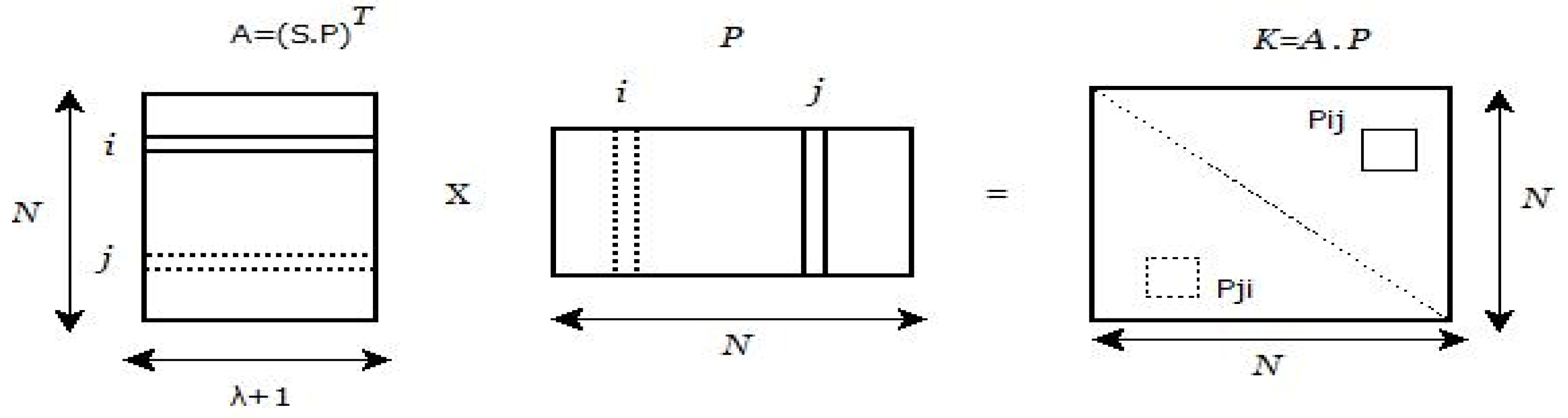
KDC performs matrix multiplication operation (Equation (3) for S and P matrices to obtain the matrix A of size N × ( + 1). Transpose operation is performed on the resultant matrix, i.e., A = .
Each device is loaded with a secret row of matrix A and a key seed of matrix P. Two devices can establish the pairwise key by exchanging their key seeds, followed by matrix multiplication operation (Figure 3). The scheme is t-collision resistant, if the columns of public matrix P are linearly independent.
3.3. ECDH Key Establishment Scheme
KDC considers the elliptic curve of form = + ax + b over field and elliptic curve domain parameters: (p, a, b, G, n, h), where p is the prime number defining the order of the finite field. The values of a and b ∈ p, such that + ≠ 0. A point G(, ) on the elliptic curve is considered as the generator point. n is the smallest positive integer such that n · G = O (point at infinity). Cofactor h = #E(Fp)n, where #E(Fp) is the number of points on the elliptic curve.
Each entity has a key pair, a private key d ∈ interval [1, n − 1] and public key Q (Q = d · G), where “·” is a scalar multiplication operation. Two devices, e.g., X and Y, with key pairs and , can compute the pairwise key (PK) as follows: Device X computes the shared secret key PK1 = . Device Y computes the shared secret key PK2 = .
4. Proposed Key Management Infrastructure Design for IACS
The proposed design aims at supporting all the common key management operations, viz. key generation, device registration, key establishment, key storage, device addition, key revocation, key update, key recovery, key archival, and key de-registration and destruction. The design considers the following communication scenarios: (i) among field level devices; (ii) among control level devices; (iii) among plant level devices; (iv) across field level and control level devices; and (v) across control level and plant level devices. The key management phases are explained as follows:
Assumptions: CKMI server is physically protected. Each device in the network has a unique ID and Join key. The Join keys are preloaded in the devices by the device manufacturing unit during the device manufacturing phase. The CKMI server has the Join keys of all the devices. It is assumed that trust is employed between the device manufacturing plant and industrial plant.
4.1. Key Generation
- Field level devices: Along with polynomial key establishment parameters (polynomial shares), 128-bit random key is generated for field level devices. The generated key is used as a field level group key (FGK) for field network devices.
- Control level devices: Along with matrix method key establishment parameters (secret rows ∈ matrix A and key seeds ∈ matrix P), 128-bit random key is generated for control level devices. The generated key is used as a control level group key (CGK) for control network devices.
- Plant level devices: Along with ECDH method key establishment parameters (public and private key pairs), 128-bit random key is generated for plant level devices. The generated key is used as a plant level group key (PGK) for plant network devices.
Algorithm 1 depicts the key generation process for IACS devices.
| Algorithm 1 Key generation for IACS devices. |
|
4.2. Device Registration/Device Join Phase
When a device is connected to the CKMI server for initial bootstrapping, the CKMI server sends a request for the device to send the resource configuration details. The device sends the unique device ID and the resource configuration details (the type of device and resource footprint (battery power, memory, and processing capacity)). The resource configuration details are encrypted using the Join key. The CKMI server authenticates the device by decrypting the received message using the Join key of the corresponding device. Based on the resource configuration details, appropriate crypto mechanisms will be loaded into the device.
- Field level devices: If the device belongs to field level category, polynomial method key establishment parameters, i.e., a polynomial share from the polynomial pool and a corresponding ID used for generating the polynomial share, are sent to the device. The keying materials are encrypted using the Join key. The FGK is loaded in all authenticated field devices for securing the broadcast messages to be sent by the CKMI server to all field level devices.
- Control level devices: The rows of matrix A are used as the key material for the devices to generate the secret key. Thus, each device will get a secret row from the secret matrix A and the corresponding column seed value from the public matrix P. The keying materials are encrypted using the Join key and sent to the control devices. The CGK is loaded in all authenticated control devices for securing the broadcast messages to be sent by the CKMI server to all control level devices. Public matrix (P) is made available in the public key directory.
- Plant level devices: If the device belongs to the plant level category, it will load the elliptic curve domain parameters and a random number (private key of the device). The keying materials are encrypted using the Join key and sent to the plant devices. The PGK is loaded in all authenticated plant level devices for securing the broadcast messages to be sent by the CKMI server to all plant level devices. The elliptic curve parameters and public keys of the devices are made available in the public key directory.
Algorithm 2 depicts the Device registration/Device join process for IACS devices.
| Algorithm 2 Device registration and Key distribution for IACS devices. |
|
4.3. Key Establishment Phase
- Field level devices: Any pair of field devices establish secure communication between themselves using their preshared polynomial shares. Sinceb devices have the polynomial shares of the same polynomial equation, they can get the same shared secret key (Section 3.1). A nonce is used to prevent the replay attack.
- Control level devices: Any pair of control devices establish secure communication between themselves using their preshared secret row and a seed value. Equation (3) and Figure 3 confirm that the same shared secret key is generated between any two control level devices (Section 3.2). A nonce is used to prevent the replay attack.
- Plant level devices: Any pair of plant devices establish secure communication between them using their preshared elliptic curve parameters. The same key is generated on both devices (Section 3.3), e.g., PD1 and PD2, because PK1 = K1 × P2 = K1 × (K2 · G) = (K2 × KD) × G = K2 × P1 = K2 × (K1 · G) = K2 × P1 = PK2, where PK1 and PK2 are the shared secret key generated between the devices, K1 and K2 are the private keys and P1 and P2 are the public keys of the devices respectively. Nonce is used to prevent the replay attack.
Algorithm 3 depicts the key establishment process for IACS devices. In Algorithm 3, PK is the pair-wise key and SK is the session key generated between the devices.
| Algorithm 3 Key establishment between IACS devices. |
|
4.4. Key Storage
CKMI server maintains all the active keys used for secure communication at field, control and plant level networks. It maintains a database containing the attributes key store reference, network ID, Device ID, key generation date, and key expiry date. The key store database contains the cryptographic keying materials of key establishment parameters of the devices (Figure 4). The records in the key store are encrypted using a password known by the crypto officer. A redundant copy of the database and key store are maintained (backup) by the CKMI server to recover the parameters if keying materials are lost.
- Field level devices: Key store contains Join key, device polynomial shares, polynomial equation and FGK used for field level network devices.
- Control level devices: Key store contains Join key, device secret rows, seed values and CGK used for control level network devices.
- Plant level devices: Key store contains Join key, elliptic curve parameters, private and public keys of the devices and PGK used for plant level network devices.
4.5. Device Addition
When a new authenticated device is required to be added to the network, it goes through the device registration phase (Section 4.2). Algorithm 4 depicts the device addition process for IACS devices.
| Algorithm 4 Device addition. |
|
- Field level devices: CKMI server installs one of the available polynomial shares using a combination of a polynomial from the polynomial pool, a polynomial share generation ID and a Field level group key.CKMI server broadcasts a message to all field level devices (encrypted using FGK) about the addition of a new device. Once the new device is deployed in the field level network, it can securely communicate with other field devices using the polynomial share received from the CKMI server.
- Control level devices: Control level devices will get stored with a secret row from matrix A and a seed value from public matrix P. In the case when no rows are available in matrix A, there is a need for generating additional rows in matrix A, which can be done as follows:
- -
- CKMI server adds one extra column to the matrix P by considering a new seed value. No modification is required in the matrix S.
- -
- To generate a new secret row in matrix A, the CKMI server performs the matrix multiplication operation for P and S matrices. Transpose operation is performed. This results in one extra row in matrix A, as shown in Figure 5. This extra row can be considered as the secret row for the new device.
- Plant level devices: The CKMI server installs the elliptic curve domain parameters, a unique private key ∈ and plant level group key for the new device.The CKMI server broadcasts a message to all plant level devices (encrypted using PGK) informing about the addition of a new device and also adds the public key of the new device to a public key directory. Once the new device is deployed in the plant level network, it can securely communicate with other plant devices using the elliptic curve parameters and the public and private keys received from the CKMI server.
4.6. Key Revocation
Once the CKMI server identifies that a device is compromised or needs to be removed for some reason, its association with the industrial network should be eliminated. Algorithm 5 depicts the key revocation process for IACS devices.
- Field level devices: CKMI server broadcasts a message containing the ID of the evicted device. The message is encrypted using FGK. After receiving such a message, the field devices update their device ID revocation list. It is assumed that each field device maintains a separate device ID revocation list.For every communication, devices check the ID of the device in the device ID revocation list. If the communication requesting device’s ID is present in that list, the device terminates the connection and informs the same to the CKMI server.
- Control level devices: CKMI server broadcasts a message containing the seed value of the evicted device. The message is encrypted using CGK. After receiving such a message, the control level devices update their seed value revocation list. It is assumed that each control level device maintains a seed revocation list. In addition, the CKMI server updates the public matrix in the public key directory by removing the column of the compromised device.For every communication, devices check the seed value of the device in the seed revocation list. If the communication requesting device’s seed value is present in the seed revocation list, the device terminates the connection and informs the same to the CKMI server.
- Plant level devices: To achieve key revocation, the CKMI server broadcasts a message containing the public key of the evicted device. The message is encrypted using PGK. After receiving such a message, the plant level devices update their public key revocation list. It is assumed that each plant level device maintains a public key revocation list. In addition, the CKMI server removes the public key of the compromised device from the public key directory.For every communication, devices check the public key of the device in the revocation list. If the communication requesting device’s public key is present in the revocation list, the device terminates the connection and informs the same to the CKMI server.
| Algorithm 5 Key revocation. |
|
4.7. Key Update
According to the security policies and requirements, the keying materials of the devices should be updated. The old parameters of the device are archived, and CKMI server is involved in updating new parameters for the devices. Algorithm 6 depicts the key update process for IACS devices.
- Field level devices: If the CKMI server wants to update the keying materials of a specific device, Join key of the device is used to send the new polynomial share and the ID used for generating the polynomial share.If the CKMI server wants to modify all the security parameters of the device, it uses a commissioning device [36]. The commissioning device is a portable device used by the commissioning engineer to configure the security parameters of the devices in the industrial plant. For field level devices, the new parameters include new polynomial share with a new ID, Join key and FGK.
- Control level devices:
- -
- If CKMI server needs to update the keying materials (secret row and seed value) of the specific control device, it changes the seed value of the corresponding device in the public matrix and performs matrix multiplication for secret symmetric matrix (S) and the updated public matrix (P). The matrix multiplication operation results in a change of only one secret row corresponding to the device, which requires a key update and remaining rows are not affected in the matrix A. The Join key of the device is used to send the new secret row and the seed value for the device. The CKMI server updates the public matrix in the public key directory.
- -
- If CKMI server wants to modify all the security parameters of the device, it uses commissioning device. For control level devices, the new parameters include a new secret row from matrix A, a seed value from the new public matrix P, Join key and CGK.
- Plant level devices:
- -
- If CKMI server needs to update the private key of the specific device, it considers a new private key (where ranges from 1 to n-1). The new private key is encrypted using the Join key and sent to the device. The public key of the device is updated in the public key directory.
- -
- If CKMI server needs to modify all the security parameters of the device, it uses commissioning device. For plant level devices, the new parameters include elliptic curve domain parameters, new private key, join key and PGK.
| Algorithm 6 Key update. |
|
4.8. Archival
Archival refers to off-line long-term storage of post-operational keys. The keying material that is no longer in regular use is archived. The cases where archiving can be needed includes instances of crypto period expiry and cases when the key material of a device is compromised.
- The archived contents for the field level devices include polynomial shares and the ID used, polynomial equation, Join key and FGK.
- Control level devices: The archived contents for the control level devices include a public matrix (seed values), secret symmetric matrix (secret rows), Join key and CGK.
- Plant level devices: The archived contents for the plant level devices include parameters of elliptic curves, the private key and Join key of the device and the PGK.
4.9. Key Recovery
If the session key is lost due to device failure or crash in communication, the IACS devices themselves regenerate the pair-wise key by repeating the operations, as discussed in key establishment phase (Section 4.3). Algorithm 7 depicts the key recovery process for IACS devices.
- Field level devices: The session key is regenerated using the polynomial shares followed by the operations, as discussed in the key establishment phase.
- Control level devices: The session key is regenerated using the secret row and seed value followed by matrix multiplication operations, as discussed in the key establishment phase.
- Plant level devices: The session key is regenerated using the private key and public key followed by scalar multiplication operations, as discussed in the key establishment phase.
In the case that all security parameters of the device are destroyed, key recovery is made by CKMI server by reinstalling the parameters using the commissioning device.
| Algorithm 7 Key recovery. |
|
4.10. Key de-Registration and destruction
CKMI server removes all the traces of keying materials from local storage, backup and archive when the usage of keying materials is no longer required. In the case of field level devices, the keying materials are polynomial key establishment parameters. In the case of control level devices, the keying materials are matrix key establishment parameters. In the case of plant-level devices, the keying materials are ECDH key establishment parameters.
4.11. Across Field Level and Control Level Devices
Along with supporting secure communications between the same level devices, the proposed scheme handles secure communications between different level devices. For secure communication between the control and field level devices, our design uses a polynomial method.
- WorkflowDuring the device registration phase (Section 4.2), along with storing the keying materials of matrix method, polynomial method parameters (a polynomial share and the ID used for generating the polynomial share) are also stored in the control level devices.The control device uses matrix method parameters to communicate devices belonging to the same level network. The control device uses polynomial method parameters to communicate with field level network devices. The key establishment process follows the same procedure as portrayed in the field-level device key establishment process (Section 4.3).
- Observations
- -
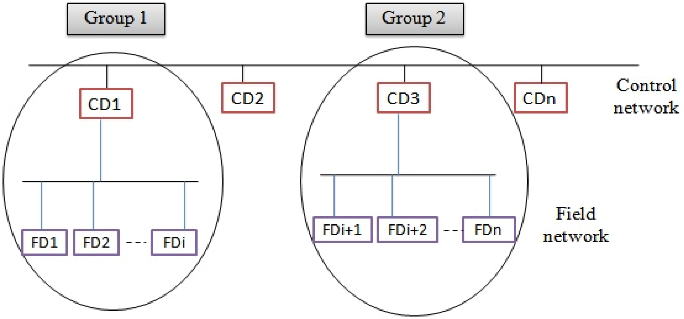
- Let us consider the scenario shown in Figure 6. The control level devices are represented by CD1, CD2, … CDn. The field level devices are represented by FD1, FD2, …, FDn. The devices CD1, FD1, …, FDi are considered as Group 1. The devices CD3, FDi+1, …, FDn are represented as Group 2.In this scenario, the field devices FD1, FD2, … FDi need to communicate only with the control device CD1. The field devices FDi+1, FDi+2, … FDn need to communicate only with the control device CD3, i.e., intergroup communication is not allowed. Hence, the CKMI server can use different polynomial equations for Group 1 and Group 2. In the key distribution phase, along with storing matrix method parameters, the device CD1 is also stored with one polynomial share of the polynomial equation, which is considered for Group 1 devices. Using the polynomial share, the device CD1 can communicate with field devices (FD1, FD2, … FDi) and vice versa. Similarly, CD3 is also stored with one polynomial share of the polynomial equation, which is considered for Group 2 devices. Using the polynomial share, the device CD3 can communicate with field devices (FDi+1, FDi+2, … FDn) and vice versa.
- -
- If similar applications are running in the industrial plant, the CKMI server can use the shares of the same polynomial equation for different groups. It enables communication between different groups of devices under different control level devices.
- -
- If applications are different between the groups, it is better to use polynomial shares of different polynomials for each group of devices. This avoids the communication between different group devices, which are running different applications.
- -
- Use of different polynomial equations for each group also reduces the impact of a network compromise. This is because, if any device is compromised, the impact will be on the compromised group. Other groups are safe and, hence, can continue their operations.
4.12. Across Control Level and Plant Level Devices
The matrix method is used to support secure communication between the control level and plant level devices.
- WorkflowDuring the device registration phase, along with storing the keying materials of ECDH method (Section 4.2), matrix method parameters (a secret row and a seed value) are also stored in the plant level devices.The plant device uses ECDH method parameters to communicate with devices belonging to the same level network. The plant device uses matrix method parameters and vice versa to communicate with control level network devices. The key establishment process follows the same procedure as described in the control level device key establishment process (Section 4.3).
- Observations
- -
- Typically, the higher level devices of the automation networks have more relaxed constraints in terms of storage, communication and computation capacity, processing speed, etc. as compared to the lower level devices. Therefore, plant-level devices are responsible for initiating communication between plant level and control level devices.
- -
- Use of symmetric method (matrix method) between Plant and Control level devices involves less computation and communication cost. To handle multiple applications and to reduce the impact of network compromise, the grouping of devices can be done, as discussed in Section 4.11 (Figure 6).
5. CKMI Design and Its Features
Figure 7 depicts our overall design of the CKMI. It has plant level network (PN), control level network (CN) and field level network (FN) and all the key management operations. The proposed CKMI design features are summarized as follows:
- Handles all common key management operations: The CKMI server plays a key role in all key management operations such as Key generation (Algorithm 1), Device registration/Device joining (Algorithm 2), Key establishment (Algorithm 3), Key update (Algorithm 6), Key recovery (Algorithm 7), Device addition (Algorithm 4), Key revocation (Algorithm 5), Key storage, Key archival and Key de-registration and destruction.
- The proposed design handles secure communication between the same and different levels of IACS devices.
- The higher is the level of the network in the hierarchy in IACS (from a field to plant network), the more the constraints are relaxed for the devices in terms of latency, computation and communication overhead, storage, etc. According to the constraints, the appropriate crypto mechanism is considered for each layer of IACS.
- Based on the resource configuration details of the devices, a suitable crypto mechanism is employed for the devices. A symmetric crypto system is employed for field and control level devices. An asymmetric crypto system is employed for plant level devices.
- Our design follows a centralized key management aspect. It offers the following benefits:
- -
- It provides a place to define unified security policies.
- -
- It provides a higher degree control of crypto keys and hence provides operational efficiency.
- -
- It provides transparency in auditing, storage and backup processes with clear separation of tasks.
- -
- A single point of failure of CKMI server can be handled with a secondary CKMI server.
- Only communications between devices authenticated by the CKMI server will occur in the network. For any device to communicate with another device, they must participate in the secret key generation. With suitable pre-shared parameters and message exchanges, the same secret key is generated on both the devices.
- The secret key is never transmitted over the network during the key establishment phase. Thus, the chances of exposure of secret keys are reduced.
- The hierarchical industrial architecture and separate crypto systems for each level of devices avoid the disruption of service due to key management in the case of device failures. In other words, device failures will not affect the comprehensive key management infrastructure operations, although the communication with that device is lost.
- The proposed scheme minimizes the number of communications for setting up the keys, which is generally one of the most resource consuming operations in these types of networks.
- Scalability is efficiently achieved at all levels of IACS.
- -
- Device addition is supported. This will not disturb the existing communications, and no modification is required in the existing devices.
- -
- Device deletion, i.e., key revocation is handled to stop the communication between the deleted device and the existing devices.
- Replay attack is eliminated using nonces during key establishment.
6. Performance Analysis
6.1. Justification of Key Establishment Mechanisms Employed for Establishing the Shared Secret Keys
Based on the constraints of IACS devices, the proposed design makes use of the polynomial method, matrix method and ECDH method to establish the shared secret keys between the devices. The selected key establishment mechanisms are well supported to handle all the key management operations effectively.
- Justification for choosing Elliptic Curve Diffie–Hellman key establishment scheme
- -
- Fewer bits: The security level of a 160-bit ECC, 1024-bit RSA, and 1024-bit DSA is similar. ECC requires fewer bits. Table 3 shows a comparison between ECC and other crypto techniques.
- -
- Power consumption: ECC crypto mechanism consumes less power for its functioning when compared to other asymmetric crypto schemes (Table 4).
- -
- Computational efficiency Use of scalar multiplication enables fast computation. ECC based scheme has a wide selection of finite fields and curves. As per crypto++ 5.6.0 benchmarks [39], the run time of ECDH key-pair generation over GF(p) 256 is 0.00287 s and the run time of ECDH key agreement over GF(p) 256 is 0.00282 s.
- -
- Discrete logarithmic problem: ECDH works on the discrete logarithm problem. It is hard to crack the private keys of the devices.
Over the past few years, elliptic curve cryptography has gained popularity and has become a standard around the world. In IACS hierarchy, when compared to control and field level devices, the plant level devices have sufficient storage and computational capabilities. From the above analysis, it can be observed that the ECDH approach is more suitable than any other public key schemes for key establishment in plant level devices. - Justification for choosing the matrix method and polynomial method key establishment schemes.
- -
- Connectivity: Any pair of devices of the same level in IACS can communicate directly.
- -
- High resilience: Both polynomial and matrix-based system are collision resistance methods, meaning that, as long as number of devices are compromised, the communication between the non-compromised devices is secure.
- -
- Less communication overhead: The number of messages exchanged to compute the shared secret key is less. In the polynomial method, the device ID is exchanged. In the matrix method, a seed value is exchanged.
- -
- Scalable: Both methods are scalable.
- -
- Less storage overhead: In the case of a polynomial method, field devices are required to store only one -degree polynomial share. Based on the degree of the polynomial, it utilizes memory and provides security. In the case of a matrix method, control devices are required to store only one secret row and a seed value. By choosing the appropriate value for , both storage and computation overhead can be optimized.
The novelty of our work resides in the fact that originally, the basic polynomial method, matrix method and ECDH method handled only key establishment, but our proposed scheme handles device addition, key storage, key revocation, key update, and key recovery in addition to the original behavior.
6.2. Security Analysis and Comparison
The key establishment schemes used in the proposed design is resilient in nature. The secure property of the schemes depend on the parameters shown in Table 5. Table 6 gives the comparison between the key management designs.
The design is resistant to the following attacks:
- Replay attack: In the proposed scheme, this attack is eliminated using nonce values during key establishment.
- Key exposure attack: In the proposed scheme, the secret key is never transmitted over the network during the key establishment phase. Alternatively, devices self-compute the keys using the pre-shared crypto parameters. Thus, the chances of exposure of secret keys are reduced.
- Man in middle attack: If the adversary is able to capture all the communication data between the devices, he will not be able to either compromise the devices or compute the secret key used for encrypting the messages. Use of digital signatures for ECDH prevents man-in-the-middle attack.
6.3. Test Setup and Implementation Results
The prototype was developed and tested for the proposed key management infrastructure for IACS. Figure 8 shows the setup of an industrial automation network with key establishment schemes. The bottom level is the field level, the middle level is the control level, and the plant level is at the top. The communication medium was Ethernet with IP based network. Each device had a unique IP address. It was assumed that the key server had loaded the crypto parameters of the key establishment schemes in the devices using a secure channel.
7. Conclusions
We have proposed an elegant key management design for IACS to handle the key management operations. The design considers all the key management operations by considering the constraints of IACS devices. The proposed design can be applied for major IACS by using suitable crypto methods such as ECDH, matrix and polynomial method. The choice of these schemes is justified. Although these crypto methods are meant for key establishment, the same methods are extended to support other key management operations. Changes made at one level of devices to incorporate key management operations does not affect the other level of devices. The impact of attack confines only to that level of devices, thus reducing the recovery time of devices. The test setup and implementation results show that the design is efficient. The proposed design is scalable and supports to secure the communications of IACS devices.
Author Contributions
All authors have equally contributed to this work.
Funding
This research was supported by Florida International University Graduate School Dissertation Year Fellowship award recieved by the author Thejas G.S.
Conflicts of Interest
The authors declare no conflict of interest.
Abbreviations
The following abbreviations are used in this manuscript:
| ASKMA | Advanced SCADA Key Management Architecture |
| BC | Broadcasting |
| CGK | Control Level Group Key |
| CKMI | Comprehensive Key Management Infrastructure |
| CN | Control Level Network |
| ECC | Elliptic Curve Cryptography |
| ECDH | Elliptic Curve Die Hellman |
| FGK | Field Level Group Key |
| FN | Field Level Network |
| HMI | Human Machine Interface |
| IACS | Industrial Automation and Control Systems |
| ICS | Industrial Control Systems |
| IEC | Intelligent Electronic Device |
| KMI | Key Management Infrastructure |
| KDC | Key Distribution Center |
| MC | Multicasting |
| NIST | National Institute of Standards and Technology |
| OPC | Open Platform Controller |
| PK | Pairwise Key |
| PN | Plant Level Network |
| PGK | Plant Level Group Key |
| PLC | Programmable Logic Controller |
| RR | RTU-RTU |
| RTU | Remote Terminal Units |
| SCADA | Supervisory Control and Data Acquisition |
| SK | Session Key |
| VPN | Virtual Private Networks |
References
- Jarmakiewicz, J.; Parobczak, K.; Maślanka, K. Cybersecurity protection for power grid control infrastructures. Int. J. Crit. Infrastruct. Prot. 2017, 18, 20–33. [Google Scholar] [CrossRef]
- Pramod, T.C.; Sunitha, N.R. Key pre-distribution schemes to support various architectural deployment models in WSN. Int. J. Inf. Comput. Secur. 2016, 8, 139–157. [Google Scholar] [CrossRef]
- Trautman, L.J.; Ormerod, P.C. Industrial cyber vulnerabilities: Lessons from Stuxnet and the Internet of Things. Univ. Miami Law Rev. 2017, 72, 761. [Google Scholar] [CrossRef]
- Pramod, T.; Sunitha, N. SCADA: Analysis of Attacks on Communication Protocols. In Proceedings of International Symposium on Sensor Networks, Systems and Security; Springer: Cham, Switzerland, 2017; pp. 219–234. [Google Scholar]
- Ding, D.; Han, Q.-L.; Xiang, Y.; Ge, X.; Zhang, X.-M. A survey on security control and attack detection for industrial cyber-physical systems. Neurocomputing 2018, 275, 1674–1683. [Google Scholar] [CrossRef]
- Knowles, W. A survey of cyber security management in industrial control systems. Int. J. Crit. Infrastruct. Prot. 2015, 9, 52–80. [Google Scholar] [CrossRef]
- Thejas, G.S.; Boroojen, K.G.; Kshitij, C.; Isha, B.; Iyengar, S.S.; Sunitha, N.R. Deep Learning-based Model to Fight Against Ad Click Fraud. In Proceedings of the 2019 ACM Southeast Conference (ACM SE ’19), Kennesaw, GA, USA, 18–20 April 2019; pp. 176–181. [Google Scholar]
- Pramod, T.C.; Boroojeni, K.G.; Amini, M.H.; Sunitha, N.R.; Iyengar, S.S. Key pre-distribution scheme with join leave support for SCADA systems. Int. J. Crit. Infrastruct. Prot. 2019, 24, 111–125. [Google Scholar]
- Thejas, G.S.; Pramod, T.C.; Iyengar, S.S.; Sunitha, N.R. Intelligent Access Control: A Self-Adaptable Trust-Based Access Control (SATBAC) Framework Using Game Theory Strategy. In Proceedings of International Symposium on Sensor Networks, Systems and Security. ISSNSS 2017; Rao, N., Brooks, R., Wu, C., Eds.; Springer: Cham, Switzerland, 2018; pp. 97–111. [Google Scholar]
- Barker, E.; Smid, M.; Branstad, D.; Chokhani, S. A framework for designing cryptographic key management systems. NIST Spec. Publ. 2013, 800, 130. [Google Scholar]
- Ray, A.; Åkerberg, J.; Gidlund, M.; Björkman, M. Initial key distribution for industrial wireless sensor networks. In Proceedings of the IEEE International Conference on Industrial Technology (ICIT), Cape Town, South Africa, 25–28 February 2013; pp. 1309–1314. [Google Scholar]
- Tawde, R.; Nivangune, A.; Sankhe, M. Cyber security in smart grid SCADA automation systems. In Proceedings of the 2015 International Conference on Innovations in Information, Embedded and Communication Systems (ICIIECS), Coimbatore, India, 19–20 March 2015; pp. 1–5. [Google Scholar]
- Krotofil, M.; Gollmann, D. Industrial control systems security: What is happening? In Proceedings of the 2013 11th IEEE International Conference on Industrial Informatics (INDIN), Bochum, Germany, 29–31 July 2013; pp. 670–675. [Google Scholar]
- Dzung, D.; Naedele, M.; Von Hoff, T.P.; Crevatin, M. Security for industrial communication systems. Proc. IEEE 2005, 93, 1152–1177. [Google Scholar] [CrossRef]
- Barker, E.; Barker, W.; Burr, W.; Polk, W.; Smid, M. Recommendation for Key Management-Part 1: General (revised); NIST Special Publication, Citeseer; NIST: Gaithersburg, MD, USA, 2006. [Google Scholar]
- Fumy, W.; Landrock, P. Principles of key management. IEEE J. Sel. Areas Commun. 1993, 11, 785–793. [Google Scholar] [CrossRef]
- Pramod, T.C.; Sunitha, N.R. KMI for SCADA and WirelessHART in IACS. In Proceedings of the 2015 IEEE 20th Conference on Emerging Technologies & Factory Automation (ETFA), Luxembourg, 8–11 September 2015; pp. 1–4. [Google Scholar]
- IEC61850. Available online: https://en.wikipedia.org/wiki/IEC_61850 (accessed on 14 November 2016).
- IEC62351. Available online: https://en.wikipedia.org/wiki/IEC_62351 (accessed on 14 November 2016).
- Beaver, C.; Gallup, D.; Neumann, W.; Torgerson, M. Key Management for SCADA. Cryptog. Information Sys. Security Dept., Sandia Nat. Labs, Tech. Rep. SAND2001-3252. Available online: https://prod-ng.sandia.gov/techlib-noauth/access-control.cgi/2001/013252.pdf (accessed on 29 May 2019).
- Dawson, R.; Boyd, C.; Dawson, E.; Nieto, J.M.G. SKMA: A key management architecture for SCADA systems. In Proceedings of the 2006 Australasian Workshops on Grid Computing and e-Research—Volume 54, Hobart, Australia, 16–19 January 2006; Australian Computer Society, Inc.: Darlinghurst, Australia, 2006; pp. 183–192. [Google Scholar]
- Choi, D.; Kim, H.; Won, D.; Kim, S. Advanced key-management architecture for secure SCADA communications. IEEE Trans. Power Deliv. 2009, 24, 1154–1163. [Google Scholar] [CrossRef]
- Choi, D.; Lee, S.; Won, D.; Kim, S. Efficient secure group communications for SCADA. IEEE Trans. Power Deliv. 2010, 25, 714–722. [Google Scholar] [CrossRef]
- Swaminathan, P.; Padmanabhan, K.; Ananthi, S.; Pradeep, R. The Secure Field Bus (SecFB) protocol-network communication security for secure industrial process control. In Proceedings of the TENCON 2006—2006 IEEE Region 10 Conference, Hong Kong, China, 14–17 November 2006; pp. 1–4. [Google Scholar]
- Kim, J.Y.; Choi, H.K. An efficient and versatile key management protocol for secure smart grid communications. In Proceedings of the 2012 IEEE Wireless Communications and Networking Conference (WCNC), Shanghai, China, 1–4 April 2012; pp. 1823–1828. [Google Scholar]
- Liu, N.; Chen, J.; Zhu, L.; Zhang, J.; He, Y. A key management scheme for secure communications of advanced metering infrastructure in smart grid. IEEE Trans. Ind. Electron. 2013, 60, 4746–4756. [Google Scholar] [CrossRef]
- Sleeper, M. Key Management for Secure Power SCADA. Dartmouth Computer Science Technical Report TR2008-628. Available online: https://www.cs.dartmouth.edu/~trdata/reports/TR2008-628.pdf (accessed on 29 May 2019).
- Cao, H.; Zhu, P.; Lu, X.; Gurtov, A. A layered encryption mechanism for networked critical infrastructures. IEEE Netw. 2013, 27, 12–18. [Google Scholar]
- Nicanfar, H.; Jokar, P.; Beznosov, K.; Leung, V.C. Efficient authentication and key management mechanisms for smart grid communications. IEEE Syst. J. 2014, 8, 629–640. [Google Scholar] [CrossRef]
- Qian, J.; Hua, C.; Guan, X.; Xin, T.; Zhang, L. A Trusted-ID Referenced Key Scheme for Securing SCADA Communication in Iron and Steel Plants. IEEE Access. 2019, 7, 46947–46958. [Google Scholar] [CrossRef]
- Wu, D.; Zhou, C. Fault-tolerant and scalable key management for smart grid. IEEE Trans. Smart Grid 2011, 2, 375–381. [Google Scholar] [CrossRef]
- Pramod, T.; Sunitha, N. Key management infrastructure design and novel techniques to establish secure communications in critical infrastructures. Int. J. Crit. Comp. Based Syst. 2017, 7, 171–189. [Google Scholar] [CrossRef]
- Blundo, C.; De Santis, A.; Herzberg, A.; Kutten, S.; Vaccaro, U.; Yung, M. Perfectly-secure key distribution for dynamic conferences. In Advances in Cryptology CRYPTO92; Springer: Berlin, Germany, 1993; pp. 471–486. [Google Scholar]
- Blom, R. An optimal class of symmetric key generation systems. In Advances in Cryptology; Springer: Berlin, Germany, 1984; pp. 335–338. [Google Scholar]
- Enge, A. Elliptic Curves and Their Applications to Cryptography: An Introduction; Springer Science & Business Media: Berlin, Germany, 2012. [Google Scholar]
- Krivoshein, K.D.; Christensen, D.D. Process Control System Including Automatic Sensing and Automatic Configuration of Devices. U.S. Patent 5,980,078, 9 November 1999. [Google Scholar]
- Stallings, W. Cryptography and Network Security, 4/E; Pearson Education India: Delhi, India, 2006. [Google Scholar]
- Potlapally, N.R.; Ravi, S.; Raghunathan, A.; Jha, N.K. Analyzing the energy consumption of security protocols. In Proceedings of the 2003 International Symposium on Low Power Electronics and Design, Seoul, Korea, 25–27 August 2003; pp. 30–35. [Google Scholar]
- Crypto++ 5.6.0 Benchmarks. Available online: http://www.cryptopp.com/benchmarks.html (accessed on 17 December 2017).
Figure 1.
Industrial automation and control systems.

Figure 2.
Key management states.

Figure 3.
Matrix method operation.

Figure 4.
Key storage.

Figure 5.
Device addition operation.

Figure 6.
Secure Communication between field and control level devices.

Figure 7.
Proposed CKMI design for IACS.

Figure 8.
Test setup of industrial automation network with key establishment schemes.


Table 1.
Key management states.
| Key Management Operations | Purpose |
|---|---|
| Key generation | Create keys |
| Key distribution | Deliver the generated keys to the intended recipient. |
| Key establishment | Communicating parties must hold the key or parameters to generate the keys. |
| Key storage | Safeguard the active keys that are used for cryptographic services. |
| Key backup | Keep a copy of the keys. |
| Key update | Replace the existing keys with new keys, when the crypto period of the key is expired or when the crypto keys are compromised. |
| Key recovery | Retrieve the lost keys from backup or archival storage |
| Key revocation | Invalidate the keys of the user/device which is compromised or when the crypto period of key is near to expiry or when user/device leaves the network. |
| Key disposal | Remove the key permanently from all the sources (user, backup and archival) |
Table 2.
Comparison of existing key management schemes for SCADA networks.
| Schemes | Crypto System Symmetric (S)/Public (P) | Centralized (C)/Decentralized (D) | Mechanism Used | Security Requirements | ||
|---|---|---|---|---|---|---|
| RR | BC | MC | ||||
| SKE [20] | Both (S) and (P) | (C) | LTK and Hash | |||
| SKMA [21] | (S) | (C) | ISO 11770-2 | ✓ | ||
| ASKMA [22] | (S) | (C) | LKH | ✓ | ✓ | |
| ASKMA+ [23] | (S) | (C) | LKH and Iolus | ✓ | ✓ | ✓ |
| BUMP IN WIRE [12] | (S) | (D) | Sec-KeyD | ✓ | ||
| SecFB [24] | (S) | (C) | DES | ✓ | ||
| SECURE POWER SCADA [27] | (P) | (D) | X.509 certificates | ✓ | ||
| Versatile KMS [25] | (S) | (C) | LTK and Hash | ✓ | ✓ | ✓ |
| Layered Defense Principle [28] | (S) | (D) | Hash chaining | ✓ | ||
| Advanced metering infrastructure [26] | (S) | (C) | Key graph | ✓ | ✓ | ✓ |
| Smart grid [29] | (P) | (D) | Identity-Based Cryptography | ✓ | ✓ | ✓ |
| Fault tolerance KMI [31] | Both (S) and (P) | (C) | Needham–Schroeder authentication protocol and elliptic curve | |||
| KMI for SCADA and WirelessHART [17,32] | (S) | (D) | Polynomial key establishment scheme | ✓ | ✓ | ✓ |
| KMI with Join/leave [8] | (S) | (D) | Symmetric Matrix | ✓ | ✓ | ✓ |
Table 3.
Comparing the key size in terms of computation effort [37].
Table 3.
Comparing the key size in terms of computation effort [37].
| Symmetric Key Size (bits) | ECC-Based Scheme (bits) | RSA/DSA (bits) |
|---|---|---|
| 56 | 112 | 512 |
| 80 | 160 | 1024 |
| 112 | 224 | 2048 |
| 128 | 256 | 3072 |
| 192 | 384 | 7680 |
| 256 | 512 | 15,360 |
Table 4.
Analyzing the energy consumption of security protocols [38].
Table 4.
Analyzing the energy consumption of security protocols [38].
| Algorithm | Key Size (bits) | Key Generation (μs) | Sign (mJ) | Verify (mJ) |
|---|---|---|---|---|
| RSA | 1024 | 270.13 | 546.5 | 15.97 |
| DSA | 1024 | 293.20 | 313.6 | 338.02 |
| ECDSA | 163 | 226.65 | 134.2 | 196.23 |
Table 5.
Secure property of the key establishment schemes.
| Key Establishment Schemes | Secure Property of the Schemes |
|---|---|
| Polynomial Key establishment scheme | collision resistance property |
| Matrix Key establishment scheme | collision resistance property |
| ECDH | Discrete logarithmic problem |
Table 6.
Comparison between the previous works and proposed work in terms of key management states supported.
Table 6.
Comparison between the previous works and proposed work in terms of key management states supported.
| Schemes | Key Management States Supported | |||||||||
|---|---|---|---|---|---|---|---|---|---|---|
| S1 | S2 | S3 | S4 | S5 | S6 | S7 | S8 | S9 | S10 | |
| SKE [20] | ✓ | ✓ | ✓ | ✓ | ||||||
| SKMA [21] | ✓ | ✓ | ✓ | ✓ | ||||||
| ASKMA+ [23] | ✓ | ✓ | ✓ | ✓ | ✓ | ✓ | ||||
| Versatile KMS [25] | ✓ | ✓ | ✓ | ✓ | ||||||
| Advanced metering infrastructure [26] | ✓ | ✓ | ✓ | ✓ | ||||||
| KMI with Join/leave [8] | ✓ | ✓ | ✓ | ✓ | ✓ | ✓ | ||||
| Proposed Scheme | ✓ | ✓ | ✓ | ✓ | ✓ | ✓ | ✓ | ✓ | ✓ | ✓ |
Note: S, State; S1, Key Generation; S2, Device Registration; S3, Key Establishment; S4, Key Storage; S5, Device Addition; S6, Key Revocation; S7, Key Update; S8, Key Recovery; S9, Key Archival; S10, Key Destruction.
Table 7.
Polynomial shares generation time.
| Degree of the Polynomial | Number of Shares (Mod Value) | Computation Time (in μs) |
|---|---|---|
| 10 | 1009 | 968 |
| 20 | 1009 | 2750 |
| 50 | 1009 | 8269 |
| 100 | 1009 | 17,705 |
Table 8.
Computation time to generate the session key in polynomial method.
| Degree of the Polynomial | Time Required to Generate Session Key (Addition and Multiplication Operations) (in μs) |
|---|---|
| 5 | 0.5 |
| 15 | 2.5 |
| 25 | 4.5 |
| 50 | 9.6 |
| 100 | 20 |
Table 9.
Time required to perform transpose operation.
| Order of the Matrix | Computation Time (in μs) |
|---|---|
| 5 × 5 | 1 |
| 10 × 10 | 4 |
| 15 × 15 | 7 |
Table 10.
Computation time to generate the session key in matrix method.
| Order of the Matrix | Computation Time (in μs) |
|---|---|
| 10 × 10 | 1.46 |
| 25 × 25 | 4.59 |
| 50 × 50 | 9.88 |
| 100 × 100 | 25.21 |
Table 11.
Elliptic curve point generation for the curve = + x + 1 (where a = 1, b = 1).
| Finite Field () | Number of Points on the Curve (Cardinality) | Computation Time (in μs) |
|---|---|---|
| 9 | 1.36 | |
| 520 | 10,000 | |
| 2173 | 210,000 | |
| 4012 | 740,000 |
Table 12.
Scalar multiplication operation in ECDH method.
| Scalar Value | Point | Computation Time (in μs) |
|---|---|---|
| 100 | (0,4,1) | 0.54 |
| 500 | (0,4,1) | 0.82 |
| 1000 | (0,4,1) | 0.89 |
© 2019 by the authors. Licensee MDPI, Basel, Switzerland. This article is an open access article distributed under the terms and conditions of the Creative Commons Attribution (CC BY) license (http://creativecommons.org/licenses/by/4.0/).
Share and Cite
MDPI and ACS Style
T. C., P.; G. S., T.; Iyengar, S.S.; Sunitha, N.R. CKMI: Comprehensive Key Management Infrastructure Design for Industrial Automation and Control Systems. Future Internet 2019, 11, 126. https://doi.org/10.3390/fi11060126
AMA Style
T. C. P, G. S. T, Iyengar SS, Sunitha NR. CKMI: Comprehensive Key Management Infrastructure Design for Industrial Automation and Control Systems. Future Internet. 2019; 11(6):126. https://doi.org/10.3390/fi11060126
Chicago/Turabian StyleT. C., Pramod, Thejas G. S., S. S. Iyengar, and N. R. Sunitha. 2019. "CKMI: Comprehensive Key Management Infrastructure Design for Industrial Automation and Control Systems" Future Internet 11, no. 6: 126. https://doi.org/10.3390/fi11060126
Note that from the first issue of 2016, this journal uses article numbers instead of page numbers. See further details here.