Integration of LTE 230 and LTE 1800 in Power Wireless Private Networks
by
 and
and
Zhengyang Ding
1, 
Weiwei Miao
1,
Mingxuan Zhang
1,
Wei Li
1,
Rui Liu
2,
Jun Zou
3,* and
Chen Xu
3 1
Information and Telecommunication Branch, State Grid Jiangsu Electric Power Company, Nanjing 210094, China
2
State Grid Electric Power Research Institute, NARI Group Corporation, Nanjing 210094, China
3
School of Electronic and Optical Engineering, Nanjing University of Science and Technology, Nanjing 210094, China
*
Author to whom correspondence should be addressed.
Future Internet 2019, 11(11), 221; https://doi.org/10.3390/fi11110221
Submission received: 25 September 2019
/
Revised: 14 October 2019
/
Accepted: 17 October 2019
/
Published: 23 October 2019
(This article belongs to the Special Issue Security and Privacy in Information and Communication Systems)
Abstract
:Power wireless private networks (PWPNs) have been highly developed in China in recent years. They provide a basis for the energy Internet of Things, which enables the exchange of energy information between devices. Although the power wireless private network is an imitation of the public cellular network, a number of special challenges remain in power private networks. Due to the lack of general standards for PWPNs at the beginning of deployment, there are now two independent PWPN systems in China: long-term evolution (LTE) 230 and LTE 1800. Each has its own core and access networks with independent hardware. In this paper, we propose a high-level design of multinetwork integration to allow LTE 230 and LTE 1800 to coexist. For core network integration, we propose a protocol controller to select the active protocol according to the user’s mode selection, since both LTE 230 and LTE 1800 evolved from the standard LTE system. For access network integration, we propose a multinetwork integration controller to help the device access the optimal cell. The simulation results show that the integrated system can retain the advantages of these two independent systems in terms of both capacity and coverage.
1. Introduction
The wide application of wireless private networks in power systems provides a convenient means of access for control services, such as distribution automation and the interaction of power supply, power grid, load, and energy storage, as well as management services, such as power consumption information collection, mobile operation, and video surveillance [1,2]. Power wireless private networks (PWPNs) have inherited the advantages of flexible networking, convenient construction, and mature application of the wireless network. Moreover, the special use of their frequency band, equipment, and network avoids the limitations of the wireless public network relating to bandwidth, delay, service interruption rate, security, and reliability. In addition, they can effectively supplement a wired transmission network and efficiently solve the “last kilometer” access problem of electric power communication and open up the “nerve endings” of the energy Internet of Things network, which has incomparable advantages over traditional wired communication and wireless public network communication systems [3,4].
In addition, with the replacement by clean and electric energies, as well as the in-depth promotion of energy reform, distributed photovoltaics, electric vehicle charging piles, and other services will experience explosive growth [5]. Therefore, the interactive mode of power supply–power grid-load-energy storage will change, requiring an overall improvement of the control and perception ability of the distribution network, and of the quasi-real-time acquisition ability of the low-voltage power network (380 kV/220 kV), so as to promote a qualitative leap of the power grid operation level and service mode. The PWPN is an important technology to realize service access and collection at the end of the power grid. As a result, increasing attention has been paid to the establishment of power wireless communication broadband private networks based on private authorized frequency bands [6,7,8,9,10]. Solar home systems (SHSs) with rooftop solar panels have proliferated in recent years. In [11], International Electrotechnical Commission (IEC) 61850-based modeling of SHS and smart meters was presented to facilitate their integration into power systems and to ensure interoperability among different devices. Smart distribution systems are crucial for realizing an envisioned smart grid. In [12], an assessment of WLAN performance for IEC 61850-based smart distribution substation applications was presented.
Research has also been conducted on powered private networks. In our previous work [13], we analyzed the requirements of power grid basic services for time-division long-term evolution (TD-LTE) wireless private networks and the effect of the collection frequency on the transmission rate demand. Moreover, the latency in the distribution automation service was also simulated. In [14], we analyzed the coverage and capacity of LoRa and narrowband Internet of Things (NB-IoT). In [15], a dynamic uplink resource scheduling algorithm was proposed on the basis of a software-defined optical network (SDON). The priority of the service was evaluated before the resource scheduling was carried out. According to the characteristics of orthogonal frequency division multiplexing (OFDM) resource allocation, and the numerical control separation and programmable features of SDON, different scheduling methods were designed for different services.
At present, domestic spectrum resources are scarce in China, and the main frequency bands have been occupied by various services. The available frequency bands for power wireless private networks are 1800 MHz and 230 MHz; 1800 MHz has other sporadic applications, so it can only be authorized for use in PWPNs after frequency clearing. There are two independent PWPN systems in these two bands: LTE 1800, which is similar to the public LTE network, and LTE 230, which is also similar to the LTE system but with a difference in subcarrier spacing. Each has advantages and disadvantages, so the two systems are better used simultaneously. This can improve the reliability and coverage according to the current research. However, this would increase the cost since two independent core networks are needed, thus requiring a significant amount of hardware. Therefore, understanding how to integrate these two private networks effectively is a challenge. In this paper, we discuss the core network and access network integration of LTE 1800 and LTE 230 and analyze the capacity of the integration system. For the core network, we discuss the integrated core network structure to combine the same unit in the two private networks. For the access network, we propose a multinetwork integration controller to help a device access the optimal cell.
2. High-Level Design of the PWPN
2.1. Architecture of the PWPN
Figure 1 shows the architecture of a power wireless private network. This is similar to the public LTE system, except that the services are all related to the power industry. The PWPN is designed for the power industry, so it is a private network. The base station can be located on the roof of a power building to reduce the cost. Renting the base station tower from the operator is another possible choice at the first phase of construction.
The main usage of the PWPN is to collect information about power usage and the real-time status of power devices. There is a large number of different services utilizing the current power public network, depending on the operator. According to latency requirements, the power services can be divided into two categories: real-time services, which have a high requirement for transmission latency, such as distribution automation and emergency repairing, and non-real-time services, such as power usage information collection, which may send data once per day [3].
2.2. LTE 1800
The TD-LTE 1800 system has a 1785–1805 MHz operation frequency [5]. In addition to the public network frequency, the Chinese government has designated two 20 MHz broadband frequency bands, 1447–1467 MHz and 1785–1805 MHz, for the construction of TD-LTE private networks for the government and important industries, that is, the 1.4 G TD-LTE system and the 1.8 G TD-LTE system. Specifically, in the “Notice on the Frequency Use of the Broadband Digital Trunking Private Network System in the 1447–1467 MHz Frequency Band (No. 59)” issued by the Ministry of Industry and Information Technology, it is proposed that that the 20 MHz in the range 1447–1467 MHz are planned to be used in government private networks, such as government networks, public safety networks, and emergency communication networks, using the time-division duplex (TDD) broadband digital trunking system. In the “Notice on the Reissue of the Frequency Use of Wireless Access Systems in the 1785–1805 MHz Frequency Band (No. 65)” issued by the Ministry of Industry and Information Technology, it is proposed that the 20 MHz in the range 1785–1805 MHz are planned to be used in the industries of transportation (urban rail transit, etc.), electric power, petroleum, and others, as well as public communication networks, using the TDD wireless access system. The industry chain of these two systems from chip, to system equipment, to testing, to devices is exactly the same as the LTE system industry chain of the operator. Its main supporting manufacturers include Huawei, ZTE, Dingqiao, and other domestic mainstream telecom equipment manufacturers.
2.3. LTE 230
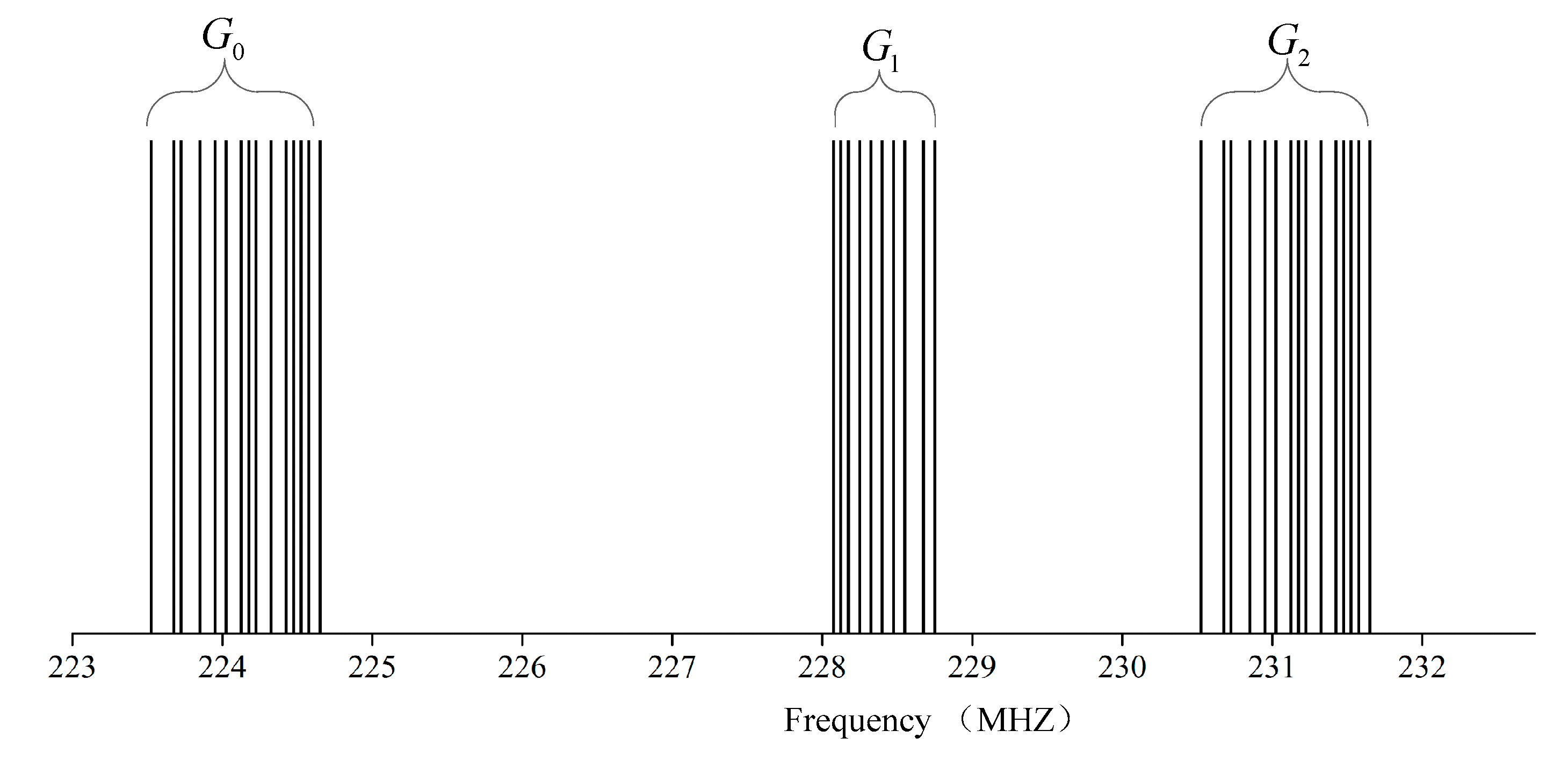
The LTE 230 system works in the 223–235 MHz frequency band, which can be used in telemetry, remote control, data transmission, and so on [16]. This section of the spectrum is allocated with 25 KHz bandwidth as a single frequency point, and the power grid system obtains a total of 40 private authorized frequency points in a discrete distribution, for a total of 1 MHz bandwidth. The distribution of the specific frequency points is shown in Figure 2. The structure is irregular and comb-shaped, and the distribution of frequency points is discrete. Among the 40 frequency points, there are 15 pairs of frequency points and 10 separate frequency points.
The LTE 230 system is an exclusive LTE system launched by Potevio, Chengdu, China. The main characteristic of the discrete power 223–235 MHz frequency band is the use of carrier aggregation technology to integrate the discrete narrowband frequency resources of the 230 MHz frequency band so as to form broadband resources to meet the requirements of power applications. In addition, the system also uses some new technologies, such as OFDM, high-order modulation, adaptive coding and modulation (AMC), and so on. On the one hand, it improves the spectrum efficiency. On the other hand, it gives the system superior demodulation performance and improves the anti-interference ability of the system, so as to ensure coexistence with other wireless systems operated at 230 MHz.
As described in the previous section, there are mainly two frequency bands, 230 MHz and 1800 MHz, which are suitable for the construction of power wireless networks in China. Jiangsu Electric Power Company has established a PWPN pilot construction using LTE 230 developed by Potevio and a PWPN pilot construction using LTE 1800 developed by Huawei, Shenzhen, China. The comparisons of these two systems are listed in Table 1.
3. Integration of the Core Network
Figure 3 shows the structure of the traditional core network and access network that are used in current commercial LTE networks. Since LTE 230 is based on the LTE system and its core network is nearly the same as that for the public LTE network (except for the details of non-access protocols), we can integrate these two systems’ core network hardware to reduce the cost and make the management easy.
Firstly, let us review the traditional core network, especially the functionality of each component. The network between base stations and the devices is called the access network and is wirelessly connected. The remaining is called the core network, which is always wire connected. In the current core network, control and transmission separation is used to increase the adaptivity to different kinds of transmission services. In the control plan, the mobility management entity (MME) is mainly used to manage the mobility of the access devices, and the home site home subscriber server (HSS) is used to manage the registration and original information of users [17].
In the data plane or user plane, there are the service gateway and packet gateway. The service gateway (S-GW) is a node connecting the access network to the core network. It acts as a mobility anchor when access devices move between base stations, as well as a mobility anchor for other 3GPP technologies. The collection of information and statistics necessary for charging is also handled by the S-GW [17].
The packet gateway (P-GW) connects the core network to the Internet. It manages the IP allocation of the access devices and the quality of service enforcement according to the policy controlled by the policy and charging rules function (PCRF). The P-GW is also the mobility anchor for non-3GPP radio-access technologies to connect to the core network [17].
As shown in Figure 4, the core network integration controller includes an S1-MME access controller and separator and an S1-U access controller. These two access controllers and the separator module are accessed to enhance the interaction ability of the dual-band base station control signal and data transmission ability. The general ideas are as follows.
(1) The MME function is realized by the LTE 230 and LTE 1800 core network, and the SGW/PGW adopts an independent protocol stack.
(2) SGW/PGW adds a transmission separator and router controller to distinguish different user equipment (UE) categories and carry out different protocol stack branch processing.
(3) Access devices and base stations of different modes are distinguished and identified during access. Independent logic branches are used to deal with devices and base stations of different modes. The control signals of different modes are sent to different protocol stacks through the access controller and separator.
(4) The uplink and downlink service data are sent to the related protocol stack to complete transmission with the help of the transmission separator and router controller in the integrated S-P/GW.
4. Integration of the Access Network
4.1. Synchronization Signal of TD-LTE 1800
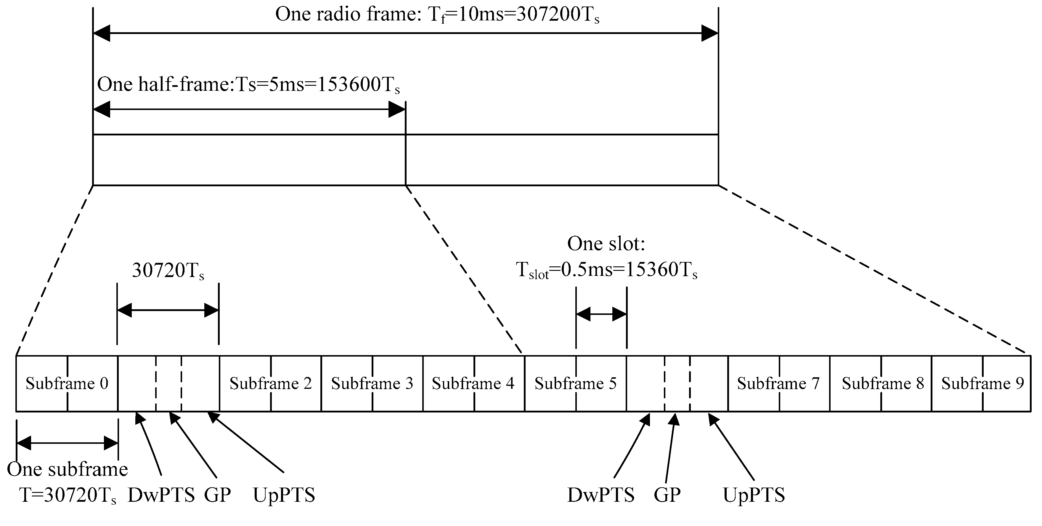
In the LTE 1800 system, is defined as the basic unit of time. One radio frame occupies in the time domain, which is divided into two half-frames of length 5 ms. One half-frame consists of five subframes. Each subframe is divided into two slots of length 0.5 ms. For normal cyclic prefix (CP), one slot consists of seven OFDM symbols. Figure 5 shows the frame structure of LTE 1800 [18].
Since the frequency allocation for the power industry is a nonpairing spectrum in China, the TDD mode is used in PWPNs. The uplink–downlink configuration can be adjusted flexibly according to Table 2, where D and U represent downlink and uplink subframes, respectively. S denotes a special subframe with the three fields DwPTS, GP, and UpPTS, which are used for downlink transmission, protection between D and U, and uplink transmission, respectively.
In the frequency domain, 12 subcarriers form a unit resource taking up 180 kHz bandwidth in total. A primary synchronization signal (PSS) is generated by the Zadoff-Chu (ZC) sequence in the frequency domain, which can be written as follows [19]:
where is the root of the ZC sequence corresponding to . In the frequency domain, the sequence is mapped to the resource elements according to
A secondary synchronization signal (SSS) is generated by an interleaved concatenation of two length-31 binary sequences. The two concatenated sequences can be written as
where . Terms and are decided by cell-identity group according to
where and are defined as
and where , is defined by
with initial conditions .
and are scrambling sequences decided by as
where , is defined by
with initial conditions .
and are also scrambling sequences, which can be written as
where , is defined by
with initial conditions .
The sequence is mapped to resource elements according to
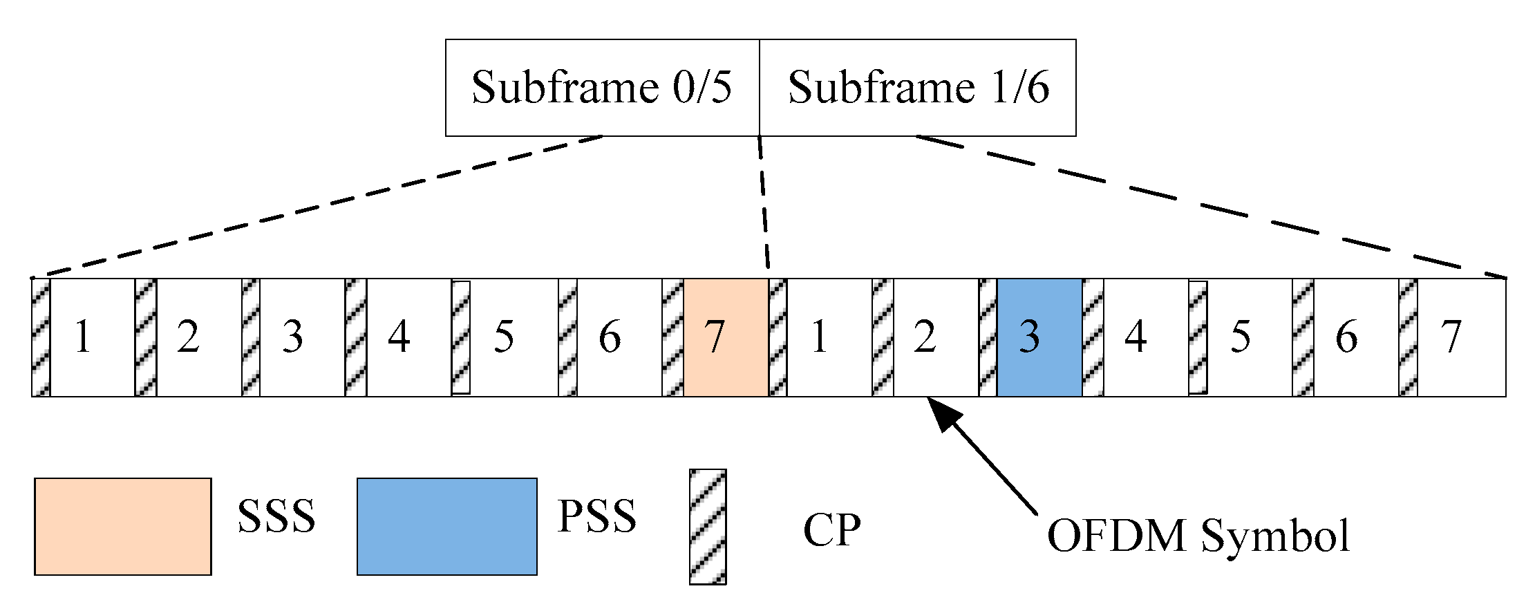
Figure 6 illustrates the distribution of the PSS and SSS in the TD-LTE 1800 subframe. The gap between the SSS and PSS is three OFDM symbols.
4.2. Synchronization Signal of LTE 230
In the LTE 230 system, is defined as the basic unit of time. One radio frame occupies in the time domain and consists of five subframes of length 5 ms. The frame structure is shown in Figure 7.
Subframe 0 is the downlink subframe, while Subframes 2, 3, and 4 are uplink subframes. Subframe 1 is a special subframe with the three fields DwPTS, GP, and UpPTS, whose functionalities are the same as in LTE 1800. The supporting uplink–downlink configurations are listed in Table 3.
A physical channel of length 25 kHz in frequency is defined as a subband, which can be classified as a synchronized subband, broadcast subband, or service subband.
In comparison with LTE 1800, there is no difference in the generation of the original 62-point sequence in the frequency domain. The difference is in the way of mapping the sequence to resource elements given LTE 230’s small bandwidth.
The PSS and SSS use the same method to solve this problem. The 62-point sequence is divided into seven parts with lengths . Each part is mapped to an OFDM symbol separately. For the PSS, the sequence is mapped to the resource elements according to
For the SSS, the sequence is mapped to resource elements according to
Then, 64-point IFFT is operated in each OFDM symbol to transform frequency domain data into time domain data. The time domain signal is finally generated by connecting the seven parts in order, with a length of 448 points.
Figure 8 illustrates the distribution of the PSS and SSS in an LTE 230 subframe.
4.3. Downlink Synchronization and Cell Search
In the LTE 1800 system, the traditional PSS detection method calculates the correlation between the received signal and the three local sequences separately [20]. The index of the local sequence which has the maximum correlation is . The corresponding time is the timing point. According to the mapping location relation between the PSS and SSS, the SSS can be found easily in the time domain. The most commonly used SSS detection method is working backwards according to the generation rule of the SSS sequence in the frequency domain. In this way, the intermediate parameters and can be acquired, which can decide .
In the LTE 230 system, the proposed PSS detection method calculates the correlation between the received signal and the three local sequences separately. The index of the local sequence which has the maximum correlation is . The corresponding time is the timing point. According to the mapping location relation between the PSS and SSS, the SSS can be found easily in the time domain. Due to the special signal mapping form, the 448-point SSS in the time domain should be firstly transformed into a 62-point original sequence in the frequency domain. The most commonly used SSS detection method is working backwards according to the generation rule of the SSS sequence in the frequency domain. In this way, the intermediate parameters and can be acquired, which can decide .
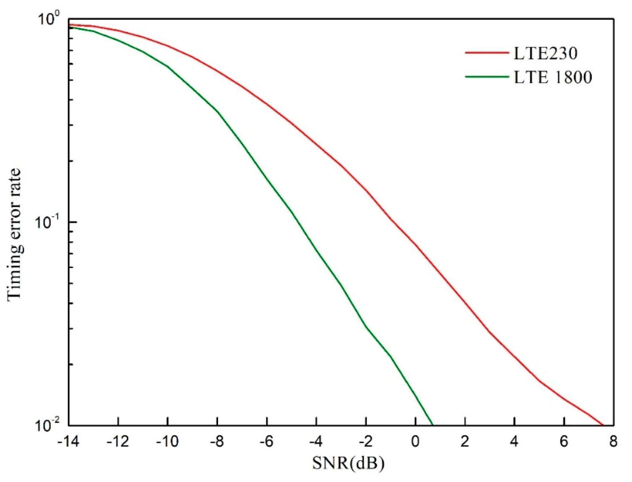
Figure 9 shows the simulation results of the timing performance of LTE 1800 and LTE 230. The simulation parameters for LTE 1800 were as follows: the subcarrier spacing was kHz, the length of the ZC sequence was 63, the root of the ZC sequence was 29, the synchronization signal period was 5 ms, and the Rayleigh channel was used. When the timing estimation error is larger than 1 us, we call it a timing detection error. The simulation parameters for LTE 230 were as follows: the subcarrier spacing was kHz, the length of the ZC sequence was 63, the root of the ZC sequence was 29, the synchronization signal period was 25 ms, and the Rayleigh channel was used. When the timing estimation error is larger than 7 us in the LTE 230 system, we call it a timing detection error.
From Figure 9, we can see that when the received SNR is larger than 1 dB, the timing error of LTE 1800 is smaller than 1%. For LTE 230, about 7 dB is needed to guarantee that the timing error rate is less than 1%. Note that the pathloss values of LTE 230 and LTE 1800 are different with the same propagation distance. The pathloss of LTE 230 is smaller than that of LTE 1800 and the fading for these two systems is independent, so we can choose the better mode with higher detection performance as the transmission mode for a given time, such as the coherent time of the channel. For example, when the received SNR of LTE 230 is 6 dB larger than it is in LTE 1800, then the device will choose LTE 230 as its communication mode in the following transmission. The received SNR can be one of the criteria used to determine which mode will be active. The details of the mode selection will be discussed in the next section.
4.4. The Access Network Integration Controller
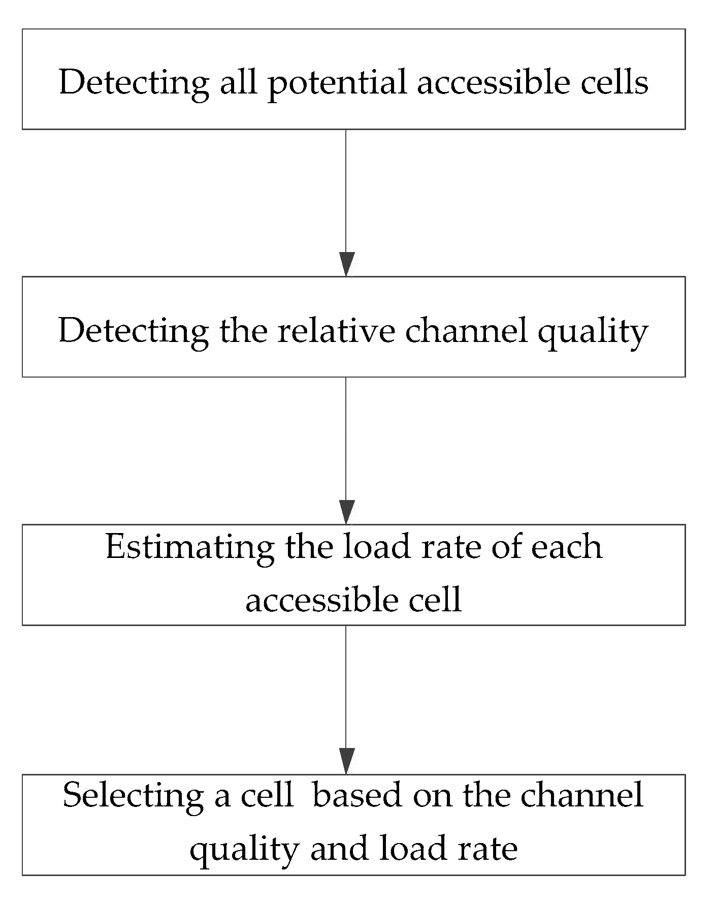
As shown in Figure 10, on the basis that we do not change the existing LTE 230 and LTE 1800 devices, the addition of a multinetwork integration controller can be used to help a device select the appropriate network for communication. The advantage of using an independent controller is that it does not need to interface with the original device. The access network integration controller only selects the equipment and is not responsible for the transmission of the data link, which is also in line with the design concept of control-transmission separation. The integration controller also has the function of simple signal reception and detection, which mainly identifies the available networks and estimates the signal quality, and only receives the downlink synchronization signal, control signal, and broadcast signal. Then, according to the actual situation of the power service, it chooses the network mode. The access network integration controller can detect the signal quality in real time or periodically and make optimal network judgments in real time. Figure 11 shows the procedure of mode selection at the device side. The main functionalities and the procedure of the access network integration controller are described as follows.
(1) Identification of Accessible Cells.
In order to detect and identify heterogeneous power wireless networks, it is necessary to extract feature information that can uniquely distinguish specific networks. Since both LTE 230 and LTE 1800 are based on LTE technology, the cell ID detected from the PSS and SSS can be used as the feature information. Whether these two modes exist or can be accessed is based on whether the device can accurately decode the information on the physical broadcast channel (PBCH). If the related PBCH can be decoded, it means that this mode exists, and vice versa. Another function of decoding the PBCH is to collect access information of the accessible network, such as the bandwidth, control channel information, etc., so as to estimate the load rate of related cells and detect the channel quality. The detection of the PSS and SSS can be realized based on correlators described in the previous section, and the decoding of the PBCH needs blind detection.
(2) Detection of Channel Quality
In order to select the appropriate network for access, it is necessary to estimate the signal strengths of the different networks, and parameters such as the receive signal strength indicator (RSSI) and SNR can be estimated according to the PSS, SSS, and PBCH. The estimated channel quality can be used for mode selection as one of the measurement basics.
(3) Estimation of the Cell Load Rate
After detecting the PSS, SSS, and PBCH of the corresponding mode, the integration controller can speculate the physical resources for the physical downlink control channel (PDCCH). The detection of the number of PDCCHs is used as an index of the load rate of the current network, which can then be used to describe the busyness degree of the network and can also be used as one of the measurement basics for mode selection.
(4) Mode Selection
Mode selection or network selection is a comprehensive tradeoff process; the factors to be considered include the channel quality, cell load rate, and the type of power service transmitted. When taking the channel quality as the measurement standard, the selection of the switching threshold is very important. We can select the threshold through simulations or practical experience. When taking the cell load rate as the measurement standard, it is necessary to consider different load balancing algorithms, such as the polling method, hash method, and so on. When taking the type of power service as the measurement standard, it is necessary to use LTE 230 as the fallback, and the system chooses LTE 1800 as the preferred access network by default. When the narrowband service is transmitted, it can be actively returned to the LTE 230 system for communication.
4.5. Performance of the Integrated Network
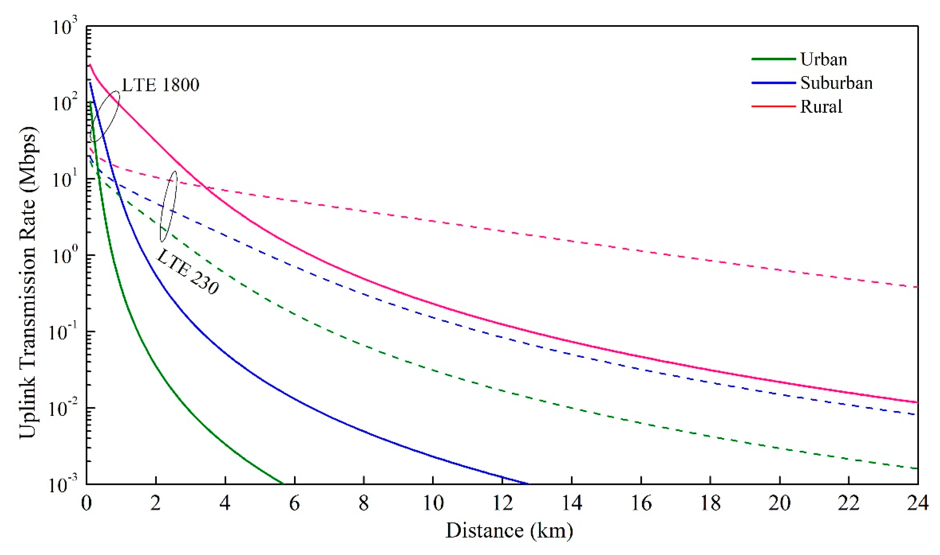
Figure 12 and Figure 13 show the transmission data rate comparisons between LTE 230 and LTE 1800. The simulation parameters were as follows: the transmitting power of the LTE 230 base station was 37 dBm, the transmitting power of the LTE 1800 base station was 49 dBm, the transmitting power of the device was 23 dBm, the system bandwidth was 1 MHz for LTE 230 and 20 MHz for LTE 1800, the height of the base station antenna was 45 m, the height of the device antenna was 1.5 m, the noise power spectrum density was -174 dBm/Hz, the noise figure was 9 dB for the device and 5 for the base station, and the gap between the real transmission rate and the Shannon capacity was assumed to be 6 dB [13,21].
We can see that there is a cross point between LTE 230 and LTE 1800. This means that after we integrate LTE 1800 and LTE 230, the transmission data rate will increase and will be determined by the better system at a given distance. For example, in the suburban area, if the device is 0.5 km away from the base station, it will use LTE 1800, which has a transmission rate much higher than that of LTE 230, as its communication mode. On the contrary, if the device moves to a place which is 8 km away from the base station, it will change to the LTE 230 mode to achieve a high transmission rate.
5. Conclusions
Power wireless private networks are very important to the energy IoT and are planned for construction in China in the next three years. There are two mature PWPNs in China currently, LTE 230 and LTE 1800, each of them having its own advantages. In this paper, we focused on the integration of these two systems. We provided high-level designs of a core network and access network to integrate LTE 230 and LTE 1800, which are both based on the LTE system and have many commonalities. In the core network integration, we separated the transmission and the control plane with two special separators and used a special access network integration controller to select the appropriate network based on the channel quality, cell load rate, service category, and so on.
Author Contributions
Software, C.X.; validation, M.Z. and R.L.; investigation, Z.D. and W.M.; writing—original draft preparation, Z.D.; writing—review and editing, J.Z. and W.L.
Funding
This research was funded by the National Natural Science Foundation of China (No. 61701234) and the technology project of State Grid Jiangsu Electric Power Company.
Acknowledgments
Acknowledgments are offered for all the partners for their active contributions and discussions during this project.
Conflicts of Interest
The authors declare no conflict of interest.
References
- Shakerighadi, B.; Anvari-Moghaddam, A.; Vasquez, J.C.; Guerrero, J.M. Internet of Things for Modern Energy Systems: State-of-the-Art, Challenges, and Open Issues. Energies 2018, 11, 1252. [Google Scholar] [CrossRef]
- Zou, J.; Yu, H.; Miao, W.; Jiang, C. Packet-Based Preamble Design for Random Access in Massive IoT Communication Systems. IEEE Access 2017, 5, 11759–11767. [Google Scholar] [CrossRef]
- Wei, L.; Miao, W.; Jiang, C.; Guo, B.; Li, W.; Han, J.; Liu, R.; Zou, J. Power wireless private network in energy IoT: Challenges, opportunities and solutions. In Proceedings of the 2017 International Smart Cities Conference (ISC2), Wuxi, China, 14–17 September 2017. [Google Scholar]
- Yu, J.; Liu, R.; Miao, W.W.; Wei, L.; Chen, X.D.; Jiang, C.L.; Guo, B.; Li, W.; Han, J.H. Research on network optimization in LTE power wireless private network. In Proceedings of the 2017 IEEE Conference on Energy Internet and Energy System Integration (EI2), Beijing, China, 26–28 November 2017. [Google Scholar]
- Wang, Y.G.; Li, Y.L.; Zheng, X.Q.; Wang, Q. Research on Reliability Optimization of 1.8 GHz TD-LTE Power Wireless Private Network. In Proceedings of the 2018 2nd IEEE Conference on Energy Internet and Energy System Integration (EI2), Beijing, China, 20–22 October 2018. [Google Scholar]
- He, L.; Yi, J.; Wang, D.; Li, M. Application Prospect of Wireless Private Network Based on Key Technology of Carrier Aggregation and Spectrum Sensing in Xinjiang Power Access Network. In Proceedings of the 2018 IEEE 3rd Advanced Information Technology, Electronic and Automation Control Conference (IAEAC), Chongqing, China, 12–14 October 2018. [Google Scholar]
- Sun, Y.; Zha, Y.; Chen, L. Robust Energy Efficiency Optimization for Coordinated Transmission with Transceiver Impairments in Private TD-LTE Wireless Network. In Proceedings of the 2018 China International Conference on Electricity Distribution (CICED), Tianjin, China, 17–19 September 2018. [Google Scholar]
- Chen, L.; Dong, X.; Wu, Z.; Liu, Z.; Chen, B. Security analysis and access protection of power distribution wireless private TD-LTE network. In Proceedings of the 2016 China International Conference on Electricity Distribution (CICED), Xi’an, China, 10–13 August 2016. [Google Scholar]
- Sun, Y.; Zhong, Y.; Wang, M. Energy-efficient coordinated multi-point transmission for centralized power wireless private TD-LTE network. In Proceedings of the 2016 China International Conference on Electricity Distribution (CICED), Xi’an, China, 10–13 August 2016. [Google Scholar]
- Yao, J.; Zhang, H.; Wei, L. Research on Planning and Evaluation Method of Spectrum Monitoring System for Power Wireless Private Network. In Proceedings of the 2019 IEEE 8th Joint International Information Technology and Artificial Intelligence Conference (ITAIC), Chongqing, China, 24–26 May 2019. [Google Scholar]
- Hussain, S.S.; Tak, A.; Ustun, T.S.; Ali, I. Communication Modeling of Solar Home System and Smart Meter in Smart Grids. IEEE Access 2018, 6, 16985–16996. [Google Scholar] [CrossRef]
- Parikh, P.P.; Sidhu, T.S.; Shami, A. A Comprehensive Investigation of Wireless LAN for IEC 61850–Based Smart Distribution Substation Applications. IEEE Trans. Ind. Inform. 2013, 9, 1466–1476. [Google Scholar] [CrossRef]
- Miao, W.W.; Wei, L.; Chen, X.D.; Jiang, C.L.; Zhang, Y.; Li, W.; Liu, R.; Zou, J. Analysis on TD-LTE wireless private network capacity meeting the interaction demand of future smart grid. J. Int. Council Electr. Eng. 2018, 8, 57–64. [Google Scholar] [CrossRef] [Green Version]
- Bao, L.; Wei, L.; Jiang, C.; Miao, W.; Guo, B.; Li, W.; Cheng, X.; Liu, R.; Zou, J. Coverage Analysis on NB-IoT and LoRa in Power Wireless Private Network. Procedia Comput. Sci. 2018, 131, 1032–1038. [Google Scholar] [CrossRef]
- Li, G.; Xu, S.; Wu, J.; Ding, H. Resource Scheduling Based on Improved Spectral Clustering Algorithm in Edge Computing. Sci. Program. 2018, 2018, 1–13. [Google Scholar] [CrossRef]
- Li, J.; Zhang, D.; Zhang, H.; Li, L.; Zhao, X.; Zheng, W.; Fang, J. Field Strength Prediction for Planning 230 MHz Electric Wireless Private Networks. In Proceedings of the 2018 24th Asia-Pacific Conference on Communications (APCC), Ningbo, China, 12–14 November 2018. [Google Scholar]
- Sesia, S.; Toufik, I.; Baker, M. LTE: The UMTS Long Term Evolution; Wiley: Hoboken, NJ, USA, 2011. [Google Scholar]
- 3GPP TS 36.211, Technical Specification Group Radio Access Network; Evolved Universal Terrestrial Radio Access (E-UTRA); Physical Channels and Modulation. Available online: https://www.etsi.org/deliver/etsi_ts/136200_136299/136211/10.03.00_60/ts_136211v100300p (accessed on 23 October 2019).
- Chu, D. Polyphase codes with good periodic correlation properties (Corresp.). IEEE Trans. Inf. Theory 1972, 18, 531–532. [Google Scholar] [CrossRef]
- Zou, J.; Xu, C. Frequency Offset Tolerant Synchronization Signal Design in NB-IoT. Sensors 2018, 18, 4077. [Google Scholar] [CrossRef] [PubMed]
- Wang, M.; Yang, W.; Zou, J.; Ren, B.; Hua, M.; Zhang, J.; You, X. Cellular machine-type communications: physical challenges and solutions. IEEE Wirel. Commun. 2016, 23, 126–135. [Google Scholar] [CrossRef]
Figure 1.
Illustration of the power wireless private network architecture.

Figure 2.
Illustration of the state grid licensed spectrum at 230 MHz.

Figure 3.
The structure of the traditional LTE system.

Figure 4.
Schematic diagram of the core network integration controller.

Figure 5.
The frame structure of the LTE 1800 system.

Figure 6.
Illustration of the primary synchronization signal (PSS) and secondary synchronization signal (SSS) in an LTE 1800 subframe.
Figure 6.
Illustration of the primary synchronization signal (PSS) and secondary synchronization signal (SSS) in an LTE 1800 subframe.

Figure 7.
Frame structure of LTE 230.

Figure 8.
Illustration of the PSS and SSS in an LTE 230 subframe.

Figure 9.
Performance comparison of the timing performance between LTE 1800 and LTE 230.

Figure 10.
An illustration of integration of the access network with a multinetwork integration controller.
Figure 10.
An illustration of integration of the access network with a multinetwork integration controller.

Figure 11.
An illustration of the cell or mode selection procedure.

Figure 12.
Downlink transmission data rate comparisons between LTE 1800 and LTE 230 in different environments.
Figure 12.
Downlink transmission data rate comparisons between LTE 1800 and LTE 230 in different environments.

Figure 13.
Uplink transmission data rate comparisons between LTE 1800 and LTE 230 in different environments.
Figure 13.
Uplink transmission data rate comparisons between LTE 1800 and LTE 230 in different environments.


Table 1.
Comparison of long-term evolution (LTE) 230 and LTE 1800.
| Technical Index | LTE 1800 | LTE 230 | Summary |
|---|---|---|---|
| Carrier Frequency Band | 1785–1805 MHz | 223–235 MHz | LTE 1800: need to apply to government departments for spectrum resources LTE 230: power private frequency point, without additional application |
| Working Bandwidth | 5–20 MHz | 1 MHz (40 discrete frequency points, each accounting for 25 KHz) | LTE 1800: has large bandwidth and supports broadband high-speed services LTE 230: has small bandwidth and supports narrowband low-speed services |
| Single Station Peak Rate | Under 5 MHz bandwidth, the downlink peak rate is 21 Mbps; the uplink peak rate is 5 Mbps | Under 1 MHz bandwidth, the uplink peak rate is 1.76 Mbps; the downlink peak rate is 0.5 Mbps | LTE 1800: supports broadband high-speed services LTE 230: supports narrowband low-speed services |
| Single Station Coverage Radius | When the station height is 45 m, it covers an area of 2–4 km in urban areas and an area of 5–7 km in suburbs | When the station height is 45 m, it covers an area of 3–5 km in urban areas and an area of 6–8 km in suburbs | LTE 230: the coverage radius is relatively large LTE 1800: the coverage radius is relatively small |
| Time delay | Millisecond level | Millisecond level | |
| Security | Based on LTE standard encryption mechanism and bi-directional identity authentication, it adopts a three-layer security encryption system to realize authentication, encryption, non-access stratum (NAS) signaling encryption, and end-to-end encryption | Based on LTE standard encryption mechanism and bi-directional identity authentication, it adopts three-layer security encryption system to realize authentication, encryption, NAS signaling encryption, and end-to-end encryption | Both have the same security policy |
| Industry Chain | Mature (Huawei, ZTE, Dingqiao, Beijing Xinwei, Potevio, etc.) | Potevio | LTE 1800: meets the global unified standard, upstream and downstream industry chain are mature. LTE 230: does not meet the global unified standard, the supporting industrial chain is inferior. |
| Application Scenarios | Supports voice, video, and data multimedia trunking services | Supports narrowband services and selectively supports multimedia transmission services | LTE 1800: video, voice, data, multimedia trunking LTE 230: data |
Table 2.
Uplink–downlink configurations of LTE 1800.
| Uplink–Downlink Configuration | Downlink-to-Uplink Switch-Point Periodicity | Subframe Number | |||||||||
|---|---|---|---|---|---|---|---|---|---|---|---|
| 0 | 1 | 2 | 3 | 4 | 5 | 6 | 7 | 8 | 9 | ||
| 0 | 5 ms | D | S | U | U | U | D | S | U | U | U |
| 1 | 5 ms | D | S | U | U | D | D | S | U | U | D |
| 2 | 5 ms | D | S | U | D | D | D | S | U | D | D |
| 3 | 10 ms | D | S | U | U | U | D | D | D | D | D |
| 4 | 10 ms | D | S | U | U | D | D | D | D | D | D |
| 5 | 10 ms | D | S | U | D | D | D | D | D | D | D |
| 6 | 5 ms | D | S | U | U | U | D | S | U | U | D |
Table 3.
Uplink–downlink configurations of LTE 230.
| Uplink–Downlink Configuration | Downlink-to-Uplink Switch-Point Periodicity | Subframe Number | ||||
|---|---|---|---|---|---|---|
| 0 | 1 | 2 | 3 | 4 | ||
| 0 | 25 ms | D | S | U | U | U |
© 2019 by the authors. Licensee MDPI, Basel, Switzerland. This article is an open access article distributed under the terms and conditions of the Creative Commons Attribution (CC BY) license (http://creativecommons.org/licenses/by/4.0/).
Share and Cite
MDPI and ACS Style
Ding, Z.; Miao, W.; Zhang, M.; Li, W.; Liu, R.; Zou, J.; Xu, C. Integration of LTE 230 and LTE 1800 in Power Wireless Private Networks. Future Internet 2019, 11, 221. https://doi.org/10.3390/fi11110221
AMA Style
Ding Z, Miao W, Zhang M, Li W, Liu R, Zou J, Xu C. Integration of LTE 230 and LTE 1800 in Power Wireless Private Networks. Future Internet. 2019; 11(11):221. https://doi.org/10.3390/fi11110221
Chicago/Turabian StyleDing, Zhengyang, Weiwei Miao, Mingxuan Zhang, Wei Li, Rui Liu, Jun Zou, and Chen Xu. 2019. "Integration of LTE 230 and LTE 1800 in Power Wireless Private Networks" Future Internet 11, no. 11: 221. https://doi.org/10.3390/fi11110221
Note that from the first issue of 2016, this journal uses article numbers instead of page numbers. See further details here.