Low Delay Inter-Packet Coding in Vehicular Networks
by
 and
and
Irina Bocharova
1,2, 
Boris Kudryashov
1,2,
Nikita Lyamin
3,
Erik Frick
4,
Maben Rabi
3 and
Alexey Vinel
3,5,* 1
Department of Information Systems, St.-Petersburg University of Information Technologies, Mechanics and Optics, 197101 St.-Petersburg, Russia
2
Institute of Computer Science, University of Tartu, 50409 Tartu, Estonia
3
School of Information Technology, Halmstad University, 30118 Halmstad, Sweden
4
AstaZero Hällered, 50491 Sandhult, Sweden
5
Department of Electrical Engineering, Western Norway University of Applied Sciences, 5063 Bergen, Norway
*
Author to whom correspondence should be addressed.
Future Internet 2019, 11(10), 212; https://doi.org/10.3390/fi11100212
Submission received: 13 August 2019
/
Revised: 29 September 2019
/
Accepted: 1 October 2019
/
Published: 11 October 2019
(This article belongs to the Special Issue 5G-V2X Communications and Networking for Connected and Autonomous Vehicles)
Abstract
:In Cooperative Intelligent Transportation Systems (C-ITSs), vehicles need to wirelessly connect with Roadside units (RSUs) over limited durations when such point-to-point connections are possible. One example of such communications is the downloading of maps to the C-ITS vehicles. Another example occurs in the testing of C-ITS vehicles, where the tested vehicles upload trajectory records to the roadside units. Because of real-time requirements, and limited bandwidths, data are sent as User Datagram Protocol (UDP) packets. We propose an inter-packet error control coding scheme that improves the recovery of data when some of these packets are lost; we argue that the coding scheme has to be one of convolutional coding. We measure performance through the session averaged probability of successfully delivering groups of packets. We analyze two classes of convolution codes and propose a low-complexity decoding procedure suitable for network applications. We conclude that Reed–Solomon convolutional codes perform better than Wyner–Ash codes at the cost of higher complexity. We show this by simulation on the memoryless binary erasure channel (BEC) and channels with memory, and through simulations of the IEEE 802.11p DSRC/ITS-G5 network at the C-ITS test track AstaZero.
1. Introduction
1.1. Safety Testing of C-ITS
The emerging concept of Cooperative Intelligent Transportation Systems (C-ITS) suggests a widespread adoption of information and communication technologies in diverse vehicular applications that aim at increasing transport safety, efficiency and comfort. C-ITS vehicles exchange information with each other as well as with roadside infrastructure over vehicular ad-hoc networks (VANETs) [1]. An important milestone for VANETs has been the worldwide allocation of reserved bandwidth for C-ITS in the 5.9 GHz spectrum. The developing communication technology is called as DSRC in USA, and ITS-G5 in Europe [2].
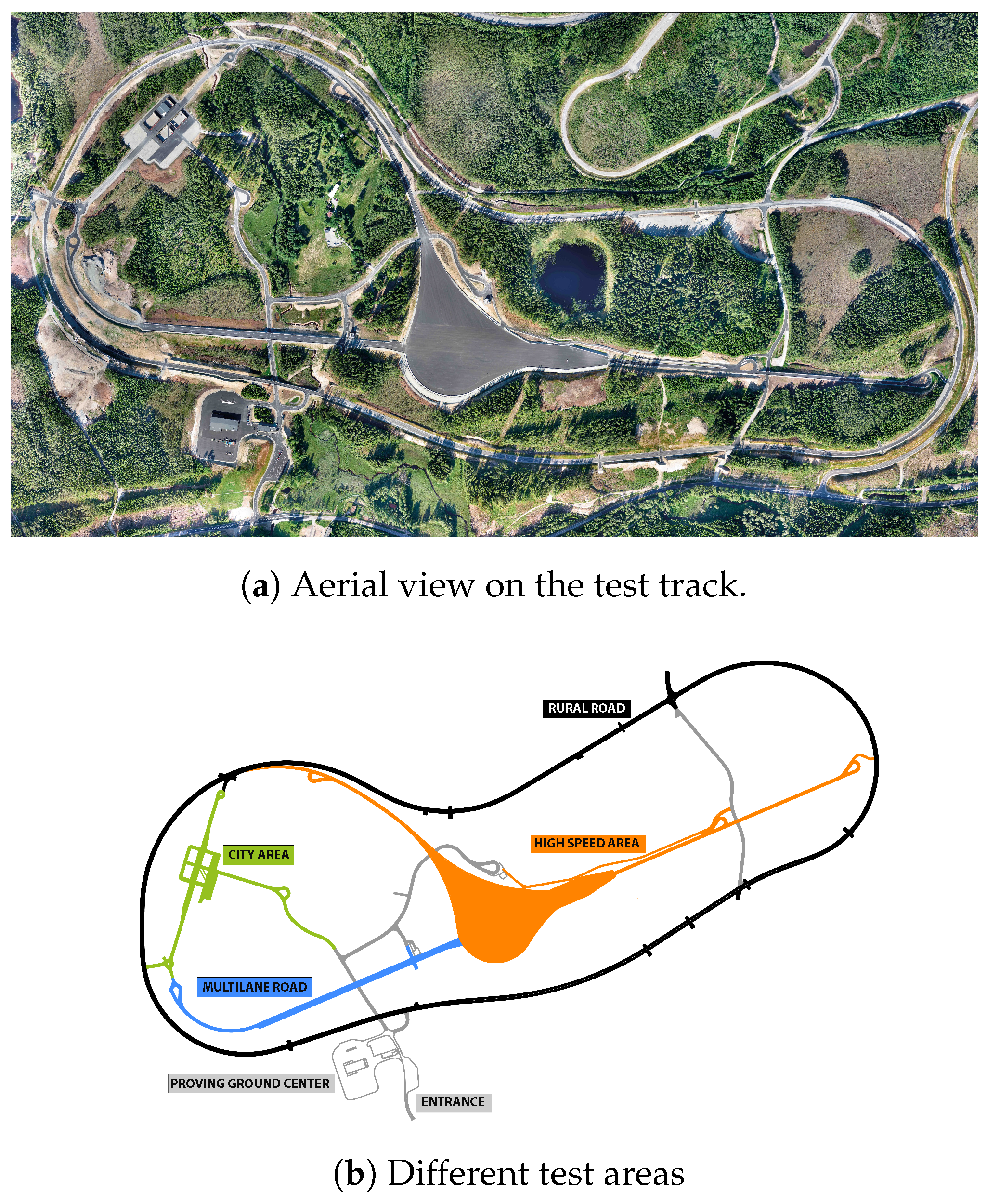
Intensive testing is being performed so that C-ITS systems could be introduced on public roads. AstaZero in Sweden is an advanced testbed for research and development in the area of active road safety and autonomous transport [3]. The unique capacities of the testbed offer the opportunity to support and accelerate research and development of active safety and C-ITS features through partnerships and close collaboration with vehicle manufacturers, suppliers, legislators, universities and colleges throughout the world. Different traffic and communication environments are available at the facility, and these make it possible to test and analyze systems from function level to vehicle integration—and this in all kinds of traffic and traffic situations (Figure 1).
1.2. Roadside Units and Quasi Real-Time Transfers
By leveraging remote connectivity supplied by Road-Side Units (RSUs) deployed along the road in VANETs, vehicles can retrieve/update maps or perform advertisement media downloading [4] via vehicle-to-roadside (V2R) communications. Moreover, vehicles may exploit storage and processing capabilities locally offered by RSUs, according to the recently proposed mobile edge computing (MEC) paradigm [5].
V2R communications are expected to be short-lived and intermittent, due to the high mobility of the vehicles and to the high costs to deploy a ubiquitous roadside infrastructure. Because of the huge data traffic demands of vehicles coupled with the limitations of V2R communications, a practical design must make the best of connectivity opportunities in drive-thru scenario, where moving vehicles spend at most a couple of minutes in the coverage area of a RSU [6,7,8]. When a non-reliable transport protocol is used, an application layer inter-packet coding turns out to be an attractive solution if we aim at transferring as many data as possible.
Drive-through scenario applies to C-ITS vehicular active safety testing also. At the AstaZero testing facility, one can test active safety by enacting carefully choreographed scenarios. Each scenario may involve multiple test objects such as vehicles, pedestrians, etc. During testing, each test object is fitted with a modem. The purpose is twofold. Firstly, the modems send and receive to and from the infrastructure, strictly real-time data consisting of trajectory updates to the test server, scenario abort signals from the test server, etc. Secondly the modems upload quasi-real time data consisting of sensor measurements and vehicular log information to the RSUs. In this way, some of the data inside the vehicle are available nearly real-time to the RSUs/server for diagnostics in the case a vehicle itself ends up damaged. It is this quasi real-time data transfer for which we design inter-packet coding.
1.3. Convolutional Codes for Inter-Packet Coding
A specific feature of packets transmission over wireless is that both burst and isolated packet losses (erasures) happen. Many papers address this problem (see, for example, [9,10] and references therein). However, low delay and low complexity requirements narrow down the list of coding techniques suitable for this application [11]. Moreover, the important feature of drive-thru scenario is a short residence time of a vehicle in the coverage area of the RSU. This restriction makes convolutional coding practically the only suitable solution to the problem.
Thorough analysis of state-of-the-art solutions for reliable data transmission in V2V and V2R communication scenarios is presented in [12]. Moreover, the batched sparse code (BATS code) [13] based protocol is suggested. BATS consists of an outer code and an inner code. The outer code represents matrix generalization of the fountain code (see [14]) and the inner code is random linear network code. The two classes of convolutional codes studied below can be suggested as low-delay alternatives to fountain codes in BATS code construction.
Another specific feature of drive-thru scenario is the existence of entrance and exit zones with extremely poor channel conditions which can be characterized by a high probability of communication failure. Since error correction coding at physical level cannot improve quality of communication in these areas, there is a need for packet level error correction. By recovering lost packets at this coding level, we increase a zone and/or an interval of reliable communication [6,7,8]. To take into account nonstationary channel conditions, we introduce a new performance measure called successful delivery function (SDF). In what follows, the studied codes are compared with respect to both conventional criteria, such as frame error rate (FER) and bit error rate (BER), and the SDF criterion.
In this paper, we study two classes of high-rate convolutional codes with sliding-window (SW)-decoding. The idea to apply convolutional codes to correct packet losses in different networks was previously considered in [9,11,15]. We compare the SW-decoding performance of the binary Wyner–Ash (WA) convolutional codes [16] and the Reed–Solomon (RS)-convolutional codes [17]. In particular, we analyze performances of SW-decoding based on maximum-likelihood (ML) decoding (SWML) and belief propagation (BP) decoding (SWBP) of window zero-tail terminated (ZT) convolutional codes [18]. A modified low-complexity iterative decoding procedure is suggested. It is shown that extending the parity-check matrix of the ZT code by a very limited number of redundant parity-checks (without changing the code) leads to the coincidence of the ML and BP decoding performance for this code.
1.4. Contributions
The new contributions of the paper are the following:
- New low-complexity low-delay decoding algorithm for erasure correction by the Wyner–Ash code applied in V2R scenario.
- Erasure-correcting performance analysis for Wyner–Ash and Reed–Solomon convolutional codes.
- Comparative analysis of suggested codes and decoding algorithms for: (i) memoryless channels; (ii) channels with memory described by Gilbert–Elliott model; and (iii) real-life VANET provided by AstaZero facility.
1.5. Organization of the Paper
In Section 2, we formulate the coding problem, and setup a performance measure (Equation (1)) appropriate for short sessions of quasi real-time packet transfers, especially when the channel conditions vary in an unknown deterministic way within the session. Two classes of convolutional codes are described and analyzed in Section 3. Simulation results are presented and discussed in Section 4. This section also includes the results of calculations based on packet loss measurements from the Asta-Zero test site. Finally, in Section 5, we indicate future lines of work that naturally emanate from our findings.
2. Preliminaries
2.1. Wireless Channels
Throughout the paper, we assume that at the physical layer data are protected by forward error correction. The information packet is organized as a series of codewords and data in the packet are protected by cyclic parity check (CRC). The probability of undetected error is negligible. Consequently, the decoder after computing CRC classifies each packet either as successfully delivered or as erased. Thus, we interpret packet losses as erasures and model packet transmission as a transmission over the binary erasure channel (BEC). In this channel, either all bits of a packet are successfully received or they all are erased. If an erasure correcting code is used, then all encoding and decoding operations are performed in parallel with all symbols of the packet. By default, in the coding theory literature it is assumed that BEC is a memoryless channel. However, in this paper, we consider both memoryless BEC and BEC with memory (M-BEC). One example of M-BEC model is obtained from the wireless fading channel model by applying discrete model constructing technique in [19,20].
2.2. Performance Metric
Our goal is to improve the reliability of communications by introducing redundancy into the transmitted data. When applying this commonly used approach to V2R communications, we meet specific problems which make it difficult to evaluate the system performance.
First, the packet losses cannot be modeled as a random stationary process. For a given vehicle and a given RSU, we distinguish poor communications zones (entry zone and exit zone) when the distance between the receiver and the transmitter is large, and so-called production zone with relatively good transmission conditions [7].
As a side effect of non-stationary channel conditions, the conventional criteria such as bit error rate (BER) or frame (word or packet) error rate (FER) do not make sense since these quantities change over time. The average overall error probability over the session is determined by the worst-case values.
To formalize the problem of improving reliability of V2R communications, we use the following approach. Let denote the probability of the packet loss at time moment t, for and where T is the total number of packets transmitted during one communication session. Assume that a message consisting of K packets should be transmitted, and the transmission is considered as successful only if all K packets are delivered to the receiver. To improve reliability, redundant packets are added to form a block of length packets, in such a way that, if the number of lost packets is , then K information packets can still be reconstructed by the decoder. More precisely, if is less than the minimum distance of the code, then lost packets can always be correctly estimated, otherwise, only some of the lost packets can be correctly estimated.
Let denote the indicator function of the successful delivery of the data packet number t in the coded system, with , and where is the total number of transmitted information packets during the session of length T packets. By definition, is equal to 1 or 0 in case of success or failure of delivering packet number t, respectively. In particular, is the probability of successful delivery of the tth packet. If the message consists of K packets then the success in delivering the entire message can written in terms of as
For a sequence of the transmitted packets, the average probability of message delivering should be computed as average over .
The successful delivery function (SDF) is defined as
This function characterizes the average (over session) probability of successful delivery of length K messages, as a function of K.
In the particular case of uncoded system, function equals the fraction of successfully delivered packets, and uncoded transmission is optimal. In general, decreases as K grows. This successful delivery function (SDF) shall be our performance measure.
In our analysis, we assume that for coverage zones of RSUs the channel parameter changes slowly with t and can be approximated as a constant value for a single block of length N. This allows us to compare coding systems using different erasure correcting codes by simulating them on the BEC with a fixed symbol erasure probability.
In addition, we compare codes using simulation on the M-BEC described by the Gilbert–Eliott model whose parameters do not change during one block of erasure correcting code. For the final evaluation, to take into account specific of drive-thru scenario, we measure SDF by simulation in real-life network conditions.
2.3. Convolutional Codes for Network Applications
Generally speaking, any error-correcting code can be used for recovering lost packets in networks. However, criteria for constructing packet erasure-correcting codes for V2R networks differ significantly from those used for evaluating codes correcting or detecting errors at the physical level. The difference stems from the difference in the acceptable decoding complexity and delay. Short lifetime of the transmitted data makes these requirements much stronger than for other networks.
Raptor codes [14] represent an efficient low-complexity network-oriented class of codes. However, they are not the best solution for the V2R application since they are meant for correcting large number of independent erasures without restriction on delay, rather than for correcting a small number of erased large packets with strictly limited delay.
Another class of codes which can be efficiently used for recovering packets of erasures are so-called codes with rank metric [21,22]. They were suggested as a generalization of codes for magnetic recording [23]. These codes protect two-dimensional data against both row and column errors and erasures. In the V2R application, it is enough to correct one-dimensional erasures which can be equally well done by the Reed–Solomon (RS)-codes [24]. The approach based on convolutional version of the RS-codes [17] is studied below as one of the solutions.
It is well known that complexity of ML decoding over the binary symmetric channel (BSC) and over the additive white Gaussian noise (AWGN) channel is, typically, an exponentially growing function of code length of block code or of constraint length of convolutional code. For this reason, usually codes with simple suboptimal decoding are preferred, e.g., concatenated codes, product codes, turbo-codes, LDPC codes, etc.
The situation is completely different for the BEC (M-BEC), where correcting of erasures can be reduced to solving a system of linear equations of order at most . Thus, ML-decoding complexity is a polynomial, at most cubic, function of code length. In this case, the decoding delay becomes a basic requirement when selecting codes. Convolutional codes, the decoding delay of which is determined by the encoder memory and does not depend on the length of the code, have practically no alternative in such an application. Low-delay high-rate convolutional codes are among most promising candidates for the V2R network application.
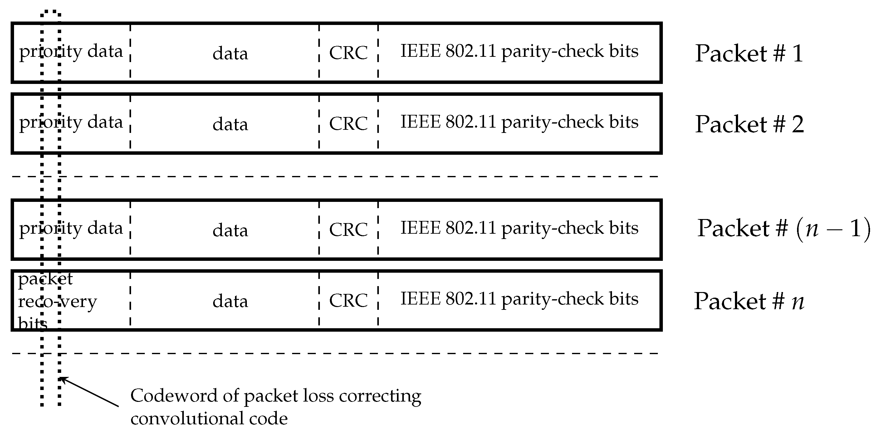
The considered further decoding scenario is shown in Figure 2.
Data packets from the physical layer of the network include data of different priority followed by cyclic redundancy check (CRC) and parity-check bits of error detecting code used in IEEE 802.11 standard. It is assumed that highest priority bits in the sequence of these packets are encoded by a convolutional code.
Two classes of binary and nonbinary high-rate convolutional codes are analyzed and compared with block codes of the same rate and approximately the same decoding delay. We demonstrate the efficiency of these codes when correcting erasures in the BEC and M-BEC obtained from the wireless fading channel by using technique in [25]. Then, the chosen codes are simulated on the stream of packet losses provided by AstaZero.
3. Packet Recovering Codes
In this section, we analyze two solutions, based on low-delay binary and nonbinary convolutional codes, respectively. Two low-complexity sliding-window (SW)-decoding procedures are studied. The first one is based on ML-decoding applied to the ZT convolutional code inside the window and the second implies conventional BP decoding and BP decoding with using redundant parity-check (RPC) matrix of the same code [26,27]. As explained below, RPC matrix contains linear dependent rows which destroy stopping sets of the code and improve erasure correcting capability compared to BP decoding while preserving low decoding complexity.
3.1. Binary Wyner–Ash Codes
3.1.1. Code Description and Distance Properties
A binary convolutional code of rate can be characterized by its semi-infinite parity-check matrix
where m denotes the code syndrome memory [18], and for each , the entry is of size .
Let us consider one block-column submatrix
If is a suitably chosen parity-check matrix of the extended Hamming code of length with minimum distance , then Equation (2) determines a subclass of Wyner–Ash codes [16] of rate with syndrome memory [18] m and free distance .
The subblock codes of the rate and Wyner–Ash codes with , respectively, are determined by parity-check matrices
The corresponding polynomial parity-check matrix of the convolutional code for
has systematic form. Its generator matrix can be written as
Generalization to an arbitrary m is obvious.
Close connection to the Hamming codes allows to compute the exact spectrum of the convolutional code determined by Equation (2) through the known spectra of Hamming codes and their cosets. This analysis was performed in [28]. For example, in case , the spectrum generating function is
In Table 1, we present the first 10 coefficients of from this paper to further use them for bounding the error probability.
3.1.2. Encoding
From Equation (7) follows a simple implementation of the systematic encoder. This encoder contains in total five delay elements, whereas for the minimal non-systematic encoder only two delay elements are required (see [18] for details). However, for the considered application, it is not important since we do not use a trellis representation of the code for ML-decoding over the BEC. The decoding complexity is at most , where is the number of corrected erasures.
Encoding delay is equal to the encoder block length since each parity-check bit is computed immediately after receiving a new block of latest information bits.
3.1.3. Decoding
As mentioned above, we study two decoding algorithms: SW-decoding and its simplified version SWBP decoding. A low-complexity modification of SWBP decoding whose error performance tends to that of SW-decoding is suggested. First, we reformulate the problem of decoding over the BEC to the problem of solving a system of linear equations.
Consider a BEC with erasure probability . Let H be an parity-check matrix of a binary block code, with the minimum Hamming distance . An ML decoder corrects any pattern of erasures if . If , then a unique correct decision can be obtained for some erasure patterns. The number of such correctable patterns depends on the code structure.
Let be a received vector, where , and the symbol represents an erasure. We denote by a binary vector, such that for all , if , and if . Let be the set of nonzero coordinates of , , and let be a vector of unknowns located in positions of .
Consider a system of linear equations which can be reduced to
where the syndrome vector is computed using the nonerased positions of and . ML decoding over the BEC is reduced to solving Equation (8).
Next, we explain SW-decoding of the convolutional code by example of the Wyner–Ash code with memory .
Let L denote the decoding delay in blocks. At each step of the decoding procedure, the SW-decoder uses a sized parity-check matrix which determines a ZT convolutional code
![Futureinternet 11 00212 i001]() where is the decoding window size in n-blocks.
where is the decoding window size in n-blocks.

Let be a semi-infinite input vector of the SW-decoder. Assuming m first blocks known (for example, all-zero) we start decoding with th block. The decision is made about blocks. After decoding (solving the system of linear equations), the recovered symbols are substituted into input sequence , the decoder outputs the (th block and the window slides by one block. At the ith step of the decoding procedure the decoder decides about
bits and outputs bits .
Example 1.
Let . Then, a parity-check matrix of the ZT code has the form
Let be the information sequence. By using the generator matrix in Equation (7) we obtain the corresponding codeword . Assume that the received sequence is .
The SW-decoder starts decoding with the sequence .
The goal is to find codeword bits at the erased positions.
- Step 1.
- Compute syndrome. The syndrome is equal to [0 0 1]. From Equation (8) followsThe number of unknowns is larger than the rank of the system which is equal to 2, that is, a unique solution does not exists. The decoder outputs only the information part of the first erasure-free block [1 1 0 0], i.e., output bits at this step are [1 1 0].
- Step 2.
- Shift the window. Input now is .The syndrome is equal to [0 0 1]. From Equation (8) followsThe unique solution is = [1 1 0]. The decoder decision is [1 1 0 1] and the output is [1 1 0]. At the next step the decoder will recover block [0 0 1 0] and the output bits are [0 0 1].
Notice that, in general, we have to perform Gaussian elimination to solve the system of linear equations. However, in our example it was not necessary. The variable is the only variable of the third equation and we found immediately that . Similarly, from the second equation, we have . Excluding known variable from the first equation, we obtain . This algorithm coincides with BP decoding used for decoding LDPC codes over the BEC. The formal description of the decoding procedure is given below as Algorithm 1. When applying Algorithm 1 to a sliding window, we obtain SWBP decoding. Next, we modify the SWBP algorithm in order to increase its erasure-correcting capability while keeping its low complexity.
| Algorithm 1 BP-BEC. |
| while there exist parity checks with only one erased symbol do |
| Assign to the erased symbol the modulo-2 sum of all nonerased symbols participating in the same parity check. |
| end while |
Since the free distance of the convolutional code is , not every combination of three erasures can be corrected by ML decoding. Thus, not every combination of three erasures can be corrected by the SW or SWBP decoding procedures. When the decoding delay L grows, the performance of SW decoder tends to the performance of the ML decoder. It means that any erasure pattern which is not a codeword and does not cover any codeword can be corrected by the SW decoder.
This is not true for SWBP decoding even if L tends to infinity. An erasure pattern cannot be corrected if it is a stopping set or it covers a stopping set [27].
The stopping set is defined as a subset of indices of columns in its parity-check matrix, such that a matrix constructed from these columns does not have a row of weight one. The size of the smallest stopping set is called stopping distance .
In general, , for the Wyner–Ash convolutional code . However, there are many combinations of weight 3 which are not codewords but are stopping sets. For example, consider the column block
The corresponding positions of the codeword form a stopping set.
Notice, that spectrum of stopping sets is determined not by code, but by its parity-check matrix. We can modify a parity-check matrix to eliminate some stopping sets, and thereby make performance of BP decoding close to that of ML decoding (see [27,29]). To do this, an additional (redundant) parity-check should be added to the code parity-check matrix.
For each window, we suggest to use the extended parity-check matrix
instead of Equation (10). The additional row is obtained as modulo 2 sum of all previous rows. It is easy to see that the former stopping set consisting of positions 9–11 (as well as many others) is not a stopping set for this matrix.
The efficiency of the decoding technique based on using the redundant parity-check (RPC) matrix will be demonstrated in Section 4.
3.2. Nonbinary Convolutional Codes
3.2.1. Code Description and Error-Correcting Properties
The advantage of the binary Wyner–Ash codes is high efficiency under very short decoding delay and extremely simple decoding algorithm.
Error-correcting properties can be further improved at the cost of additional decoding complexity if instead of binary digits we consider c-tuples of bits or even entire packets as message symbols.
The corresponding convolutional code will be a code over the Galois field extension GF(). Generalization of the Wyner–Ash construction to nonbinary alphabets for correcting independent errors and error bursts was presented in [17], where these codes are called “Reed–Solomon (RS) convolutional codes”. Here, we analyze efficiency of these codes when used for correcting erasures or recovering lost packets in the network.
For simplicity, we consider rate codes with memory . A semi-infinite parity-check matrix of the code has the form of Equation (2), where the main submatrix in Equation (3) is equal to
and denotes a primitive element of the field GF().
Theorem 1.
Proof.
Let denote a sequence of numbers of the erased positions on the 1st, 2nd, etc. subblocks of length n. It is enough to prove that any erasure pattern such that
will be recovered using SW decoding, and there exists an uncorrectable erasure pattern of weight 4. To prove the negative statement, consider the sequence . Three parity checks of the matrix in Equation (12) will contain four unknown variables and, therefore, a unique decision does not exist.
To prove that all erasure patterns of three or fewer erasures will be corrected, we show that the following two statements are true:
- 1.
- Any erasure pattern such that and , for any N will be corrected.
- 2.
- Any erasure pattern such that , will be corrected.
The first property follows from the fact that the corresponding subblock codes are the RS-codes of length and . The second property follows from the fact that any three columns belonging to different subblocks are linearly independent if and the Vandermond matrix in Equation (12) is non-degenerate [24].
In other words, for the worst case , the corresponding columns of the parity-check matrix have the form
where , . These columns are linearly independent, therefore, correction of such erasure pattern is guaranteed. □
We already proved that uncorrectable erasure patterns of weight four having their ones in one subblock cannot be corrected. In what follows, we show that if four erasures are located in different subblocks then such erasure patterns can always be corrected.
Theorem 2.
Proof.
According to Property 1 of Theorem 1, all correctable erasure patterns of weight four having their ones in one block cannot be corrected. Thus, there are uncorrectable erasure patterns.
Now, consider erasure patterns of weight four whose erasures are located in different subblocks. According to the listed above code properties, only combination requires an additional analysis. The corresponding equations with respect to the unknowns are determined by the parity-check matrix
The determinant of Equation (13) is
The equality is equivalent to the equality
and never happens if since , is a basis field element and, consequently, it has binary representation of Hamming weight 1. Then, the Hamming weight of the binary representation of the LHS of Equation (14) is equal to either 1 or 3. Therefore, determinant of the system is nonzero and there are no nontrivial solutions of weight less or equal to four. □
More detailed analysis for the case allows computing the generating function of weights of unrecoverable erasure patterns as a function of formal variable D
where and are polynomials of degree 20 and 16, respectively. Probability of packet loss after decoding can be expressed via as follows
where is the channel erasure probability. The series expansion of Equation (15) is
where denotes the ith coefficient in series expansion of , that is, the number of uncorrectable erasure patterns of weight i. It was found numerically that for the first eight coefficients are enough to compute with high precision. The first coefficients in Equation (16) are given in Table 2.
3.2.2. Encoding and Decoding for the RS-Convolutional Codes
We do not obtain a generator matrix of the RS-convolutional code. Instead, we construct a codeword in the systematic form calculating a single parity-check symbol of each subblock recursively.
A semi-infinite parity-check matrix of the RS-convolutional code is defined by Equations (2) and (12). The encoding procedure can be simplified by rewriting columns of in Equation (12) in the reverse order. In particular, for and , the reordered matrix has the form
Denote by
the information part of . The codeword of the RS-convolutional code over GF() can be written in the form where are message blocks consisting of three information symbols from GF() and are the corresponding parity-check symbols. Denote by a partial syndrome computed for the information block. It is easy to see that the first check symbol , the next one depends on , etc. The following recurrent equations describe encoding for the RS-convolutional code.
Notice that, if the field extension parameter , then all elements of parity-check matrix in Equation (12) have the Hamming weight 1 and all multiplications in Equation (18) are implemented as simple cyclic shifts.
For the RS-convolutional codes SWML-decoding is implemented similarly to that for the binary WA codes. The difference is that the parity-check matrix is more dense (does not contain zeros on non-trivial positions) and arithmetic operations are performed over the field GF().
4. Numerical Results
In this section, we compare the codes and coding techniques described in Section 3. Only codes with syndrome memory are studied since they provide the smallest delay and lowest complexity requirements. First, in Section 4.1, we consider a memoryless channel (BEC) and study influence of the code and decoder parameters on the packet-recovering performance. In Section 4.2, we investigate performance of the Wyner–Ash and the RS-convolutional codes in the channel with memory (M-BEC) where packet losses are generated according to the Gilber–Elliott model obtained from the fading channel model as explained in [19,20].
4.1. Memoryless Channel (BEC)
As a channel model, we consider the BEC with erasure (packet loss) probability .
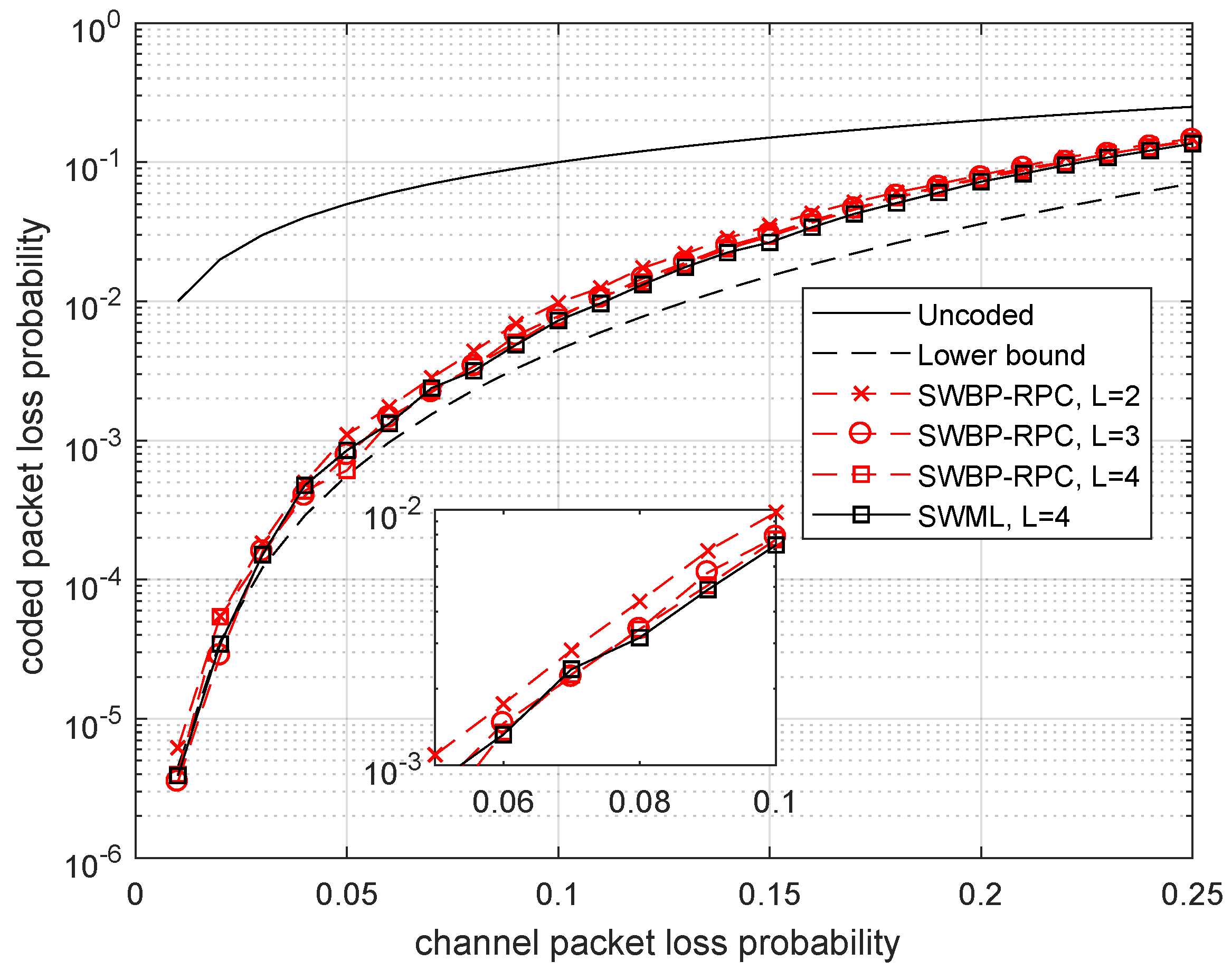
In Figure 3, we compare the probability of packet loss after decoding the Wyner–Ash code by using two decoding methods: the maximum-likelihood SW-decoder (SWML decoder) with delay and subblock length and the SWBP-decoder with one redundant parity check (SWBP-RPC decoding) with delays , 3, 4. We do not show the SWML decoding performance for and 3 since the corresponding plots differ negligibly from the plot for .
In addition, we present a lower bound on the decoding performance without restrictions on the decoding delay. This bound is obtained from the spectrum of the Wyner–Ash code presented in Table 1. Only the first term is taken into account, and this gives:
The plots shown in Figure 3 demonstrate that both SWBP-RPC and SWML decoding provide the packet recovering performance rather close to the lower bound. Therefore, the delay value is enough for achieving near optimum performance almost in the entire range of packet loss rates . In addition, we noticed that the decoding performance is not critical with respect to the decoding delay and is an acceptable value. Moreover, a very simple SWBP-RPC decoder performs almost as good as the more complicated (yet simple) SWML decoder requiring Gaussian elimination for correcting erasures.
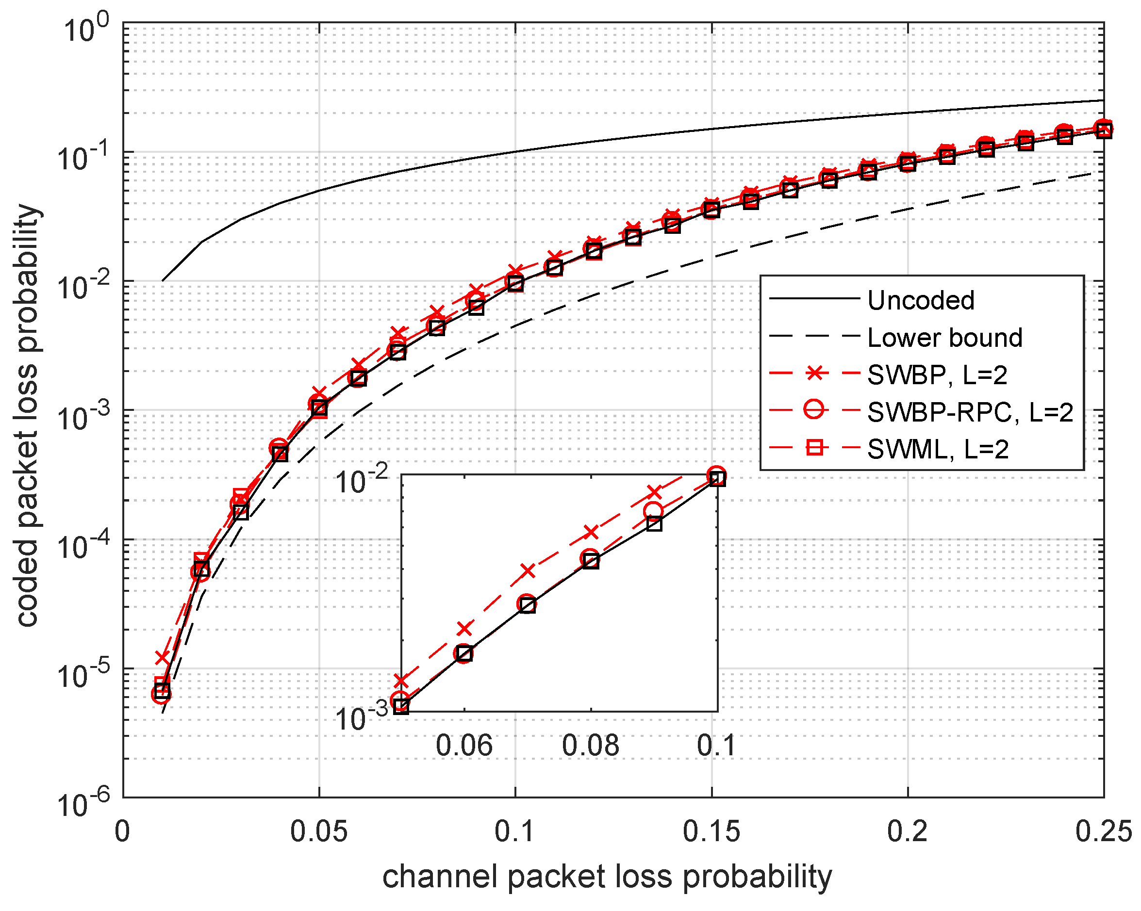
In Figure 4, we analyze the coding gain from using SWBP-RPC decoding compared to SWBP decoding. We chose decoding delay since it follows from the previous plot that increasing delay does not improve the performance significantly. We conclude from this plot that even the SWBP decoder works very well. However, it is worth using the SWBP-RPC decoder because of an additional gain in performance which can be obtained at the cost of negligible increase in decoding complexity.
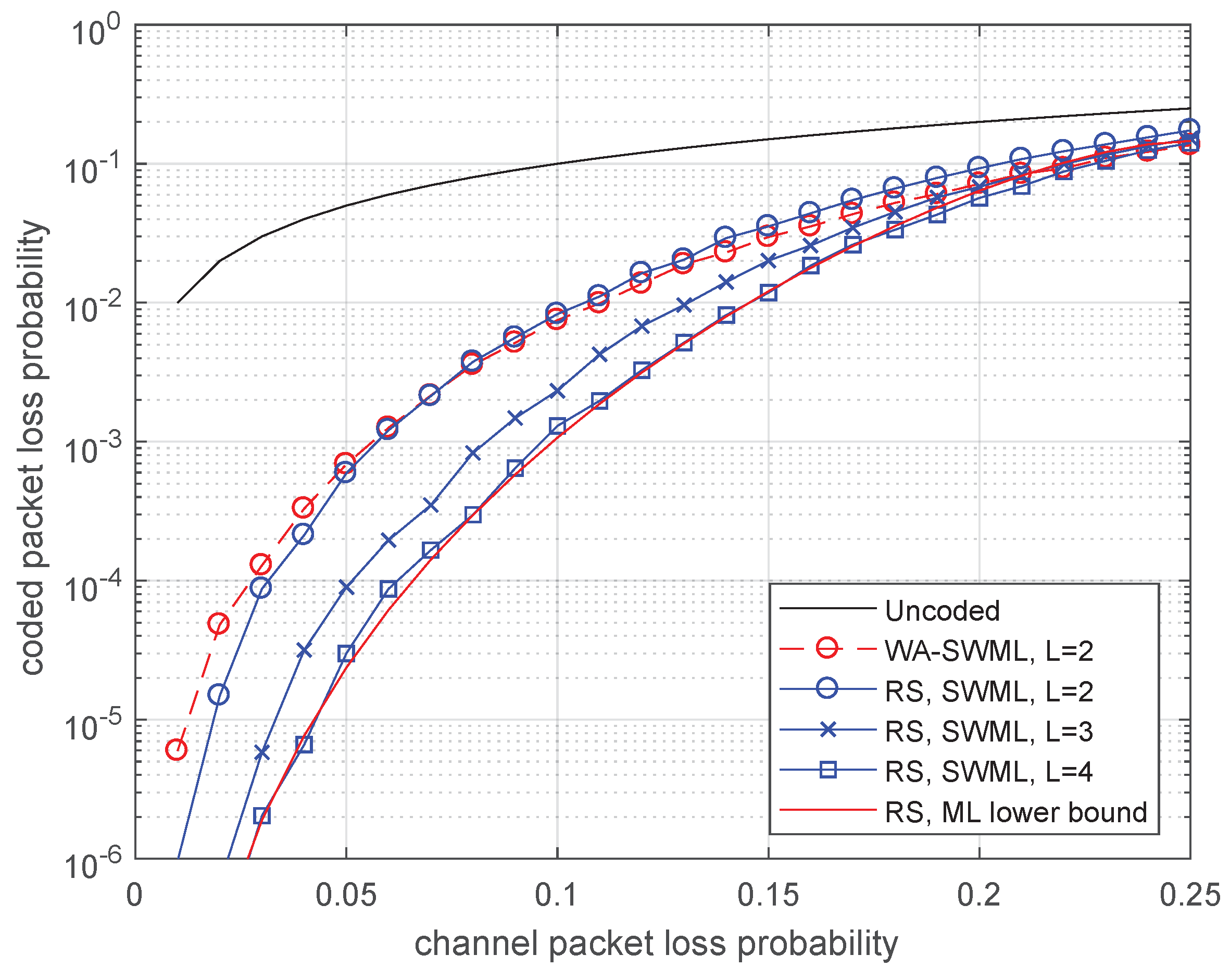
In Figure 5, binary and nonbinary (RS) convolutional coding efficiency is compared. Surprisingly, when the decoding delay is small, , the two codes have near the same efficiency. However, if the allowed decoding delay grows, the RS convolutional codes become more efficient. We also compare the packet loss probability with the lower bound in Equation (16) achievable without restriction on the decoding delay. Again, we can see that the SWML-decoder for the RS convolutional code achieves near optimal performance already for . Notice that, if L grows, then the decoding complexity grows approximately proportional to .
It is interesting to compare efficiency of the considered convolutional codes to block codes under the same delay constraints. Delay and 4 correspond to the length of block codes and 20, respectively. The block codes of rate with the best minimum distance for given length and rate were chosen for comparison.
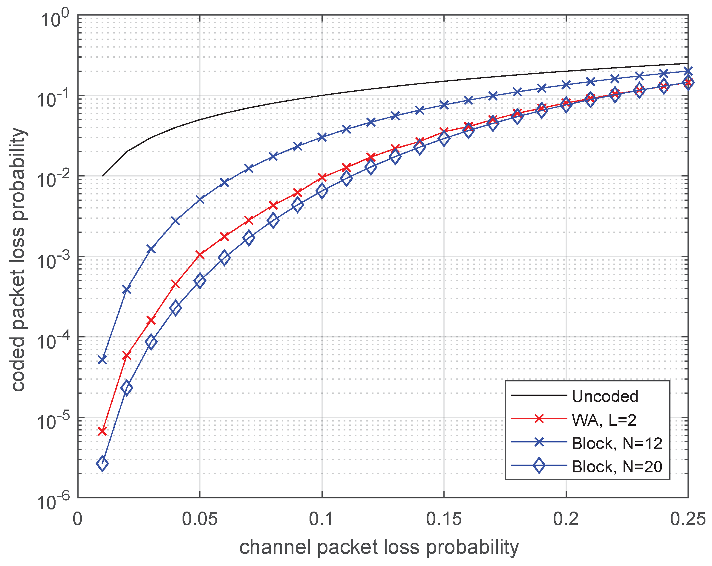
In Figure 6, the comparison is done for binary codes. The convolutional code with delay provides almost the same efficiency as the block code with code length . Moreover, typically, if one erasure occurs, then the SWML decoder outputs the result with delay at most 4, whereas the decoder of block code processes the entire codeword of length 20.
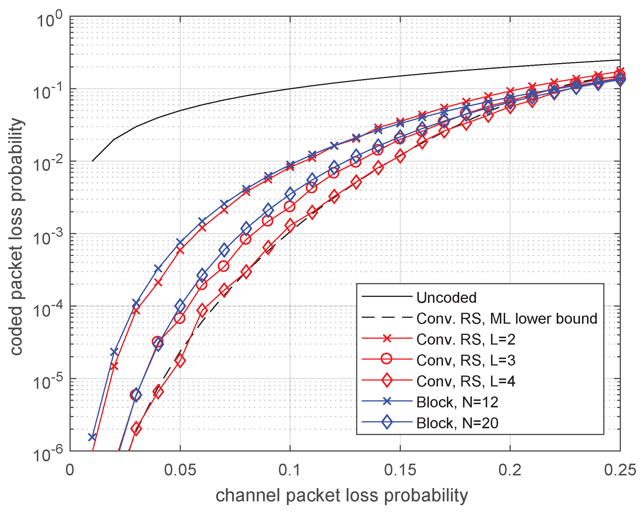
In Figure 7, we can see that the relation between nonbinary RS-block and RS-convolutional codes differs from that for binary codes. The RS-block code of length 12 loses very little compared to the RS-convolutional code. With increasing delay, the advantage of convolutional codes increases. Notice that the decoding complexity for the convolutional code is less than that for the block codes since its parity-check matrix is more sparse.
4.2. Channel with Memory (M-BEC)
In this subsection, we compare performance of the binary WA codes and the RS-convolutional codes on the erasure channel with memory. We model this channel as a discrete approximation of the fading channel. The Rice fading channel model is determined by signal-to-noise ratio , correlation coefficient and coefficient characterizing the ratio of energies of regular and random components of the received signal. If , we obtain the Rayleigh fading channel. We approximate this channel by the Gilbert–Elliott model using technique in [19,20]. See also the tutorial in [30] for overview of approaches to constructing finite-state discrete approximations of analog wireless channel models.
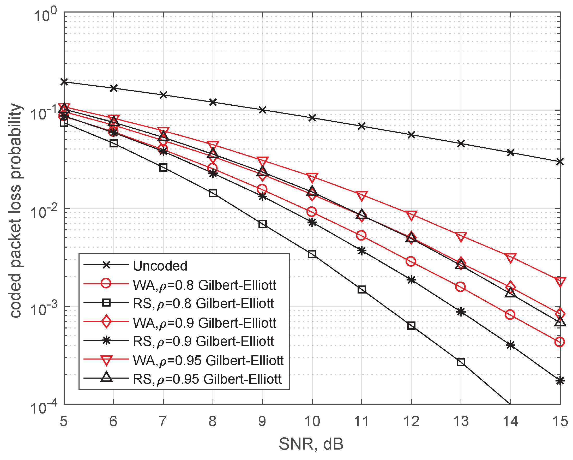
In Figure 8, the same codes with SWML-decoding are compared over the Gilbert–Elliott model approximating the Rayleigh fading with , , and [19,25]. The decoding performance rapidly degrades with increasing correlation coefficient. Larger delay codes are superior with respect to the codes with . The obtained coding gain decreases from 2 dB to 1 dB with increasing from 0.8 to 0.95.
4.3. Probability of Message Successful Delivering for AstaZero Scenario
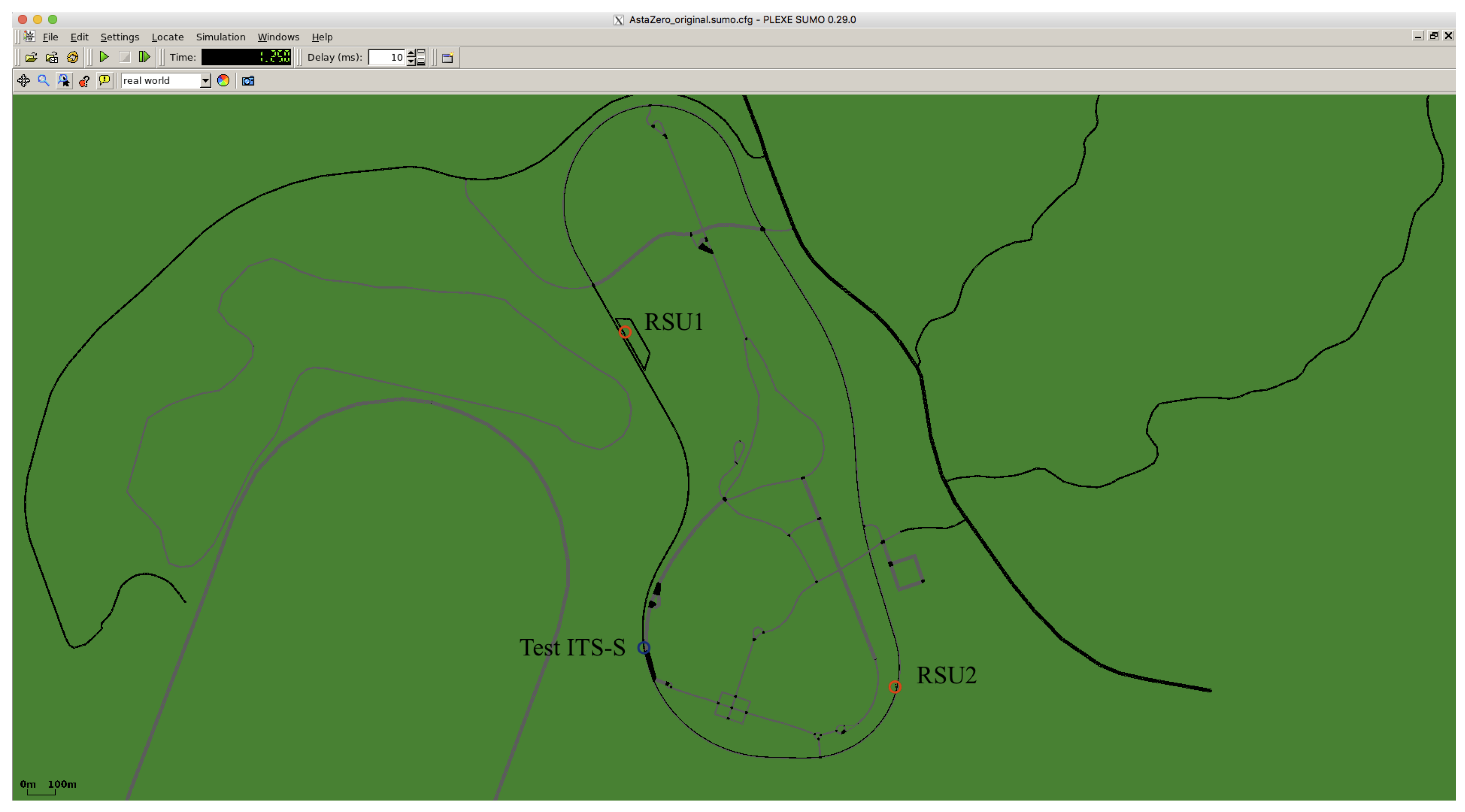
In Figure 9, the general view of the rural test area of AstaZero is shown. We consider two RSUs that are placed such that, together, they cover most of the test track.
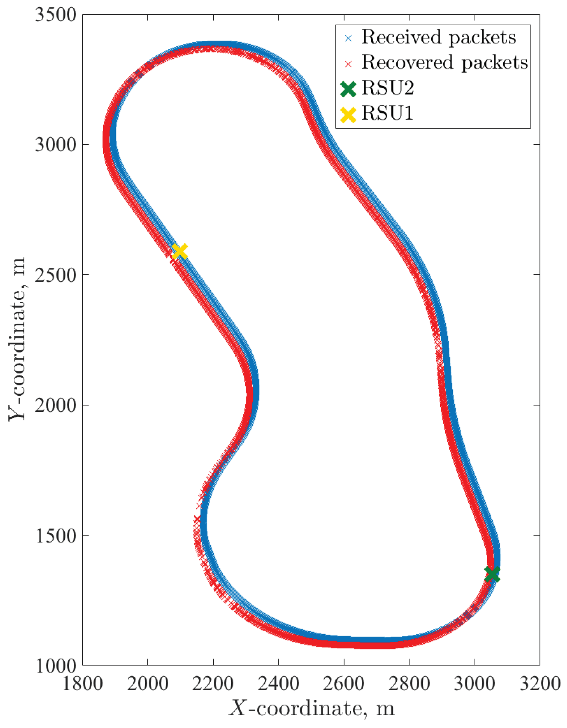
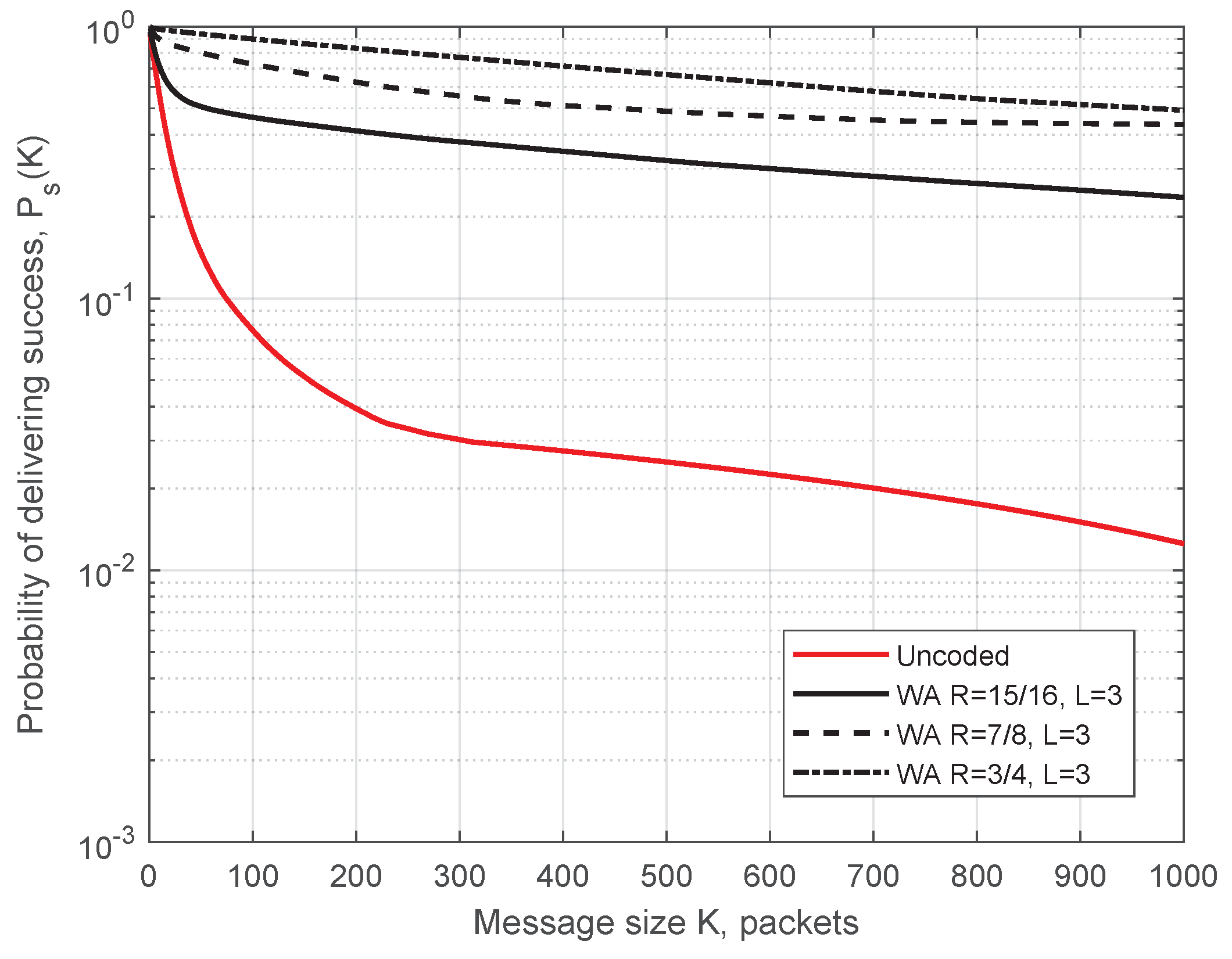
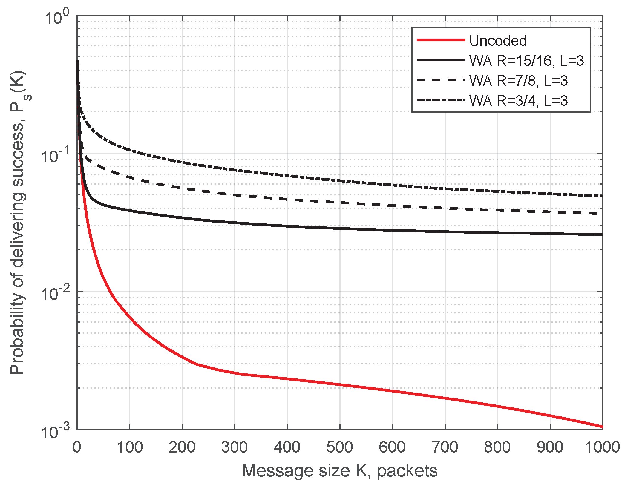
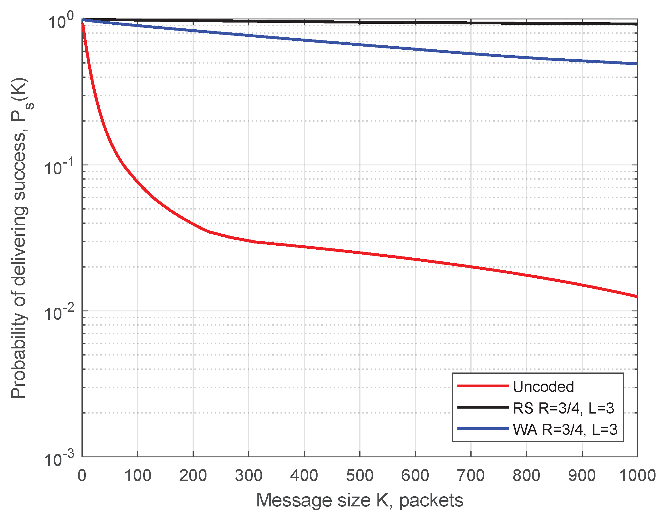
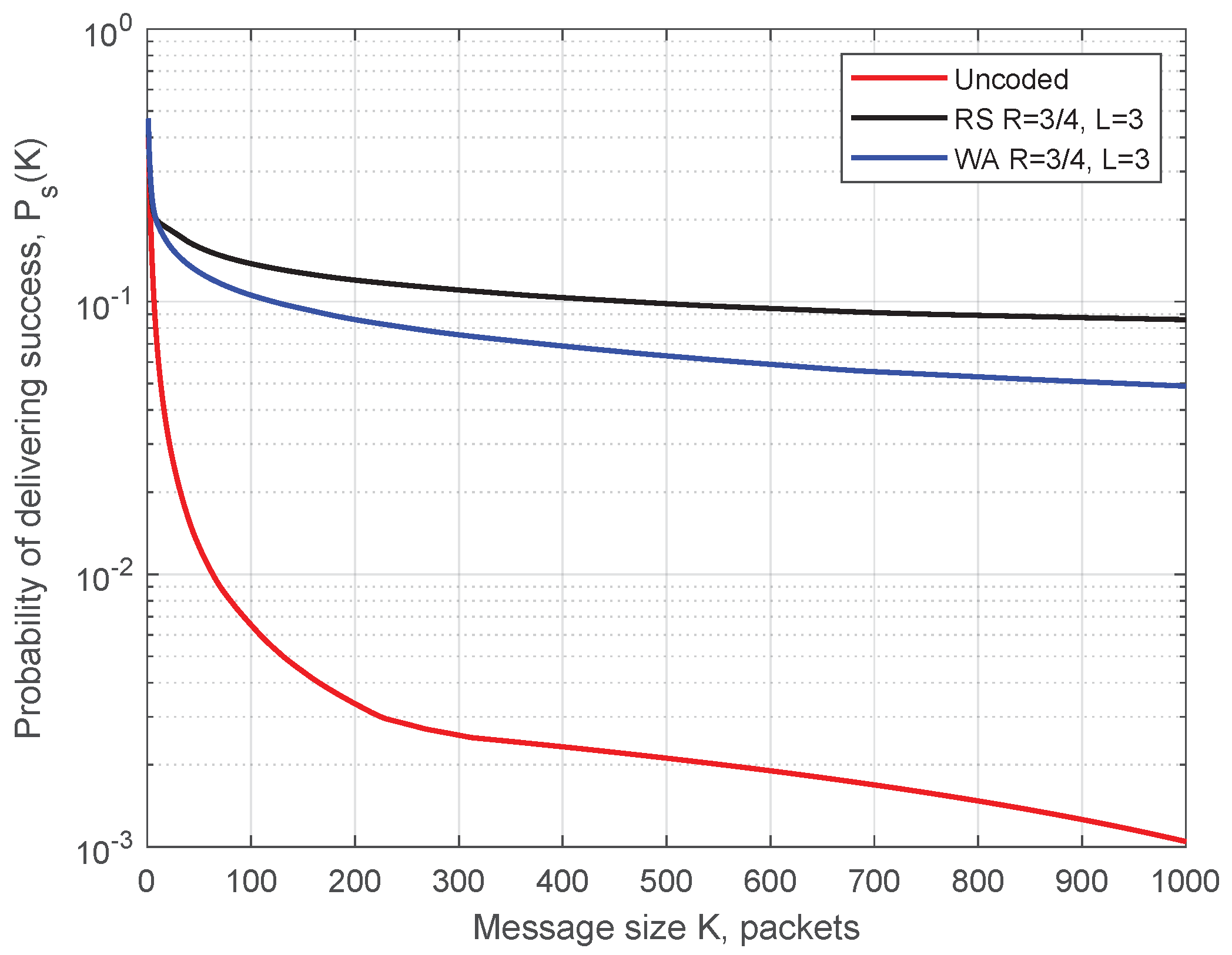
Simulation parameters for Figure 10 are as follows: transmission power 200 mW (23 dBm—maximum allowed power on control ITS-G5 channel), datarate 6 Mbit/s, packet size 400 Bytes, ITS-s generates 1500 msg/s, m = 1 in the Nakagami-m model, simulation time 425 s (time for one full circuit drive on the test track with the constant speed of 50 km/h), and the code rate . In Figure 10, blue circles demonstrate the packets received before decoding, and red crosses depict packets additionally recovered by the decoder. (For representational purposes, all the points for recovered packets were moved 20 m to the left.) Predictably, the demonstrated performance is best next to each RSU, when ITS-s resides in the production zone. Here, we present the simulated probability of successful delivering (SDF) determined by Equation (1) as a function of message length K. The WA and RS convolutional codes under SWML decoding are considered. In Figure 11 and Figure 12, we show the SDFs for the WA binary convolutional codes used over the production zone and over the entire session, respectively. In Figure 11 and Figure 12, the SDFs obtained for different code rates and for uncoded transmission are compared. As follows from the presented plots, the lower is the code rate, the better is the reliability of packet delivery that can be achieved. However, it seems that decreasing the code rate below does not lead to a significant improvement and this rate can be considered as a reasonable choice. During the production zone, successful delivering of message of length up to 1000 packets is highly probable. For the entire session, only about 10% of long messages will be delivered even for the coded system.
In Figure 13 and Figure 14, we compare the WA codes versus the RS codes for the production zone and for the entire session, respectively. We conclude that the RS codes provide better reliability of the transmission compared to the WA codes but at the cost of higher computational complexity.
Both classes of codes demonstrate high reliability of delivering long message during the production zone.
5. Conclusions
In summary, we have shown that significant gains come through our proposed erasure codes. From the figures of the previous section, it is clear that there is a significant difference in the probability of successful delivery, between codes and uncoded transmissions. Our new algorithm has low delay and low complexity, and is based on Wyner–Ash convolutional codes. We conducted an erasure performance analysis for both these Wyner–Ash convolutional codes, and also for corresponding ones based on Reed–Solomon convolutional codes. Thus, our main recommendation for V2R communications is to apply erasure codes for boosting packet reception rates.
Our future work towards the support of C-ITS safety testing is planned in three main directions.
First is the experimental proof-of-concept validation of the developed inter-packet coding scheme, to be performed at AstaZero.
Secondly, we are planning to propose such inter-packet coding in the ongoing ISO 22133-1 standardization of messages formats and communication protocols for automotive testing facilities.
Finally, we intend to address tighter requirements on decoding delays. The studied coding scheme introduces some delays which are acceptable for non-critical (quasi real-time) VANET scenarios such as maps updates, but these delays are not acceptable for hard real-time data traffic (e.g., the tracking of objects under test). Therefore, designing of appropriate coding schemes which meet the reliability requirements for hard real-time C-ITS applications will be a subject of our future work.
Author Contributions
Conceptualization E.F. and A.V.; methodology and formal analysis, B.K. and I.B.; software, N.L.; investigation, B.K., I.B., M.R., N.L. and A.V.; writing—original draft preparation, B.K. and I.B.; writing—review and editing, M.R.; supervision, A.V.
Funding
The research leading to the results reported in this work has received funding from the Knowledge Foundation in the framework of AstaMoCA “Model-based Communication Architecture for the AstaZero Automotive Safety” project (2017–2019), COST Action CA15127 (“Resilient communication services protecting end-user applications from disaster-based failures—RECODIS”) supported by COST (European Cooperation in Science and Technology), Swedish Foundation for Strategic Research (SSF) in the framework of Strategic Mobility Program (2019–2020), from Eesti Teadusagentuur under the grant PRG49 and from the ELLIIT Strategic Research Network. This support is gratefully acknowledged.
Conflicts of Interest
The authors declare no conflict of interest.
References
- Zheng, K.; Zheng, Q.; Chatzimisios, P.; Xiang, W.; Zhou, Y. Heterogeneous Vehicular Networking: A Survey on Architecture, Challenges, and Solutions. IEEE Commun. Surv. Tutor. 2015, 17, 2377–2396. [Google Scholar] [CrossRef]
- Sjoberg, K.; Andres, P.; Buburuzan, T.; Brakemeier, A. Cooperative Intelligent Transport Systems in Europe: Current Deployment Status and Outlook. IEEE Veh. Technol. Mag. 2017, 12, 89–97. [Google Scholar] [CrossRef]
- AstaZero Test Site. Available online: http://www.astazero.com/ (accessed on 10 October 2019).
- ETSI. Intelligent Transport Systems (ITS); Vehicular Communications; Basic Set of Applications; Definitions; ETSI TS 102 638 V1.1.1 (2009-06); ETSI: Valbonne, France, 2014. [Google Scholar]
- Zhang, K.; Mao, Y.; Leng, S.; Maharjan, S.; Vinel, A.; Zhang, Y. Contract-theoretic Approach for Delay Constrained Offloading in Vehicular Edge Computing Networks. Mob. Netw. Appl. 2018, 1–12. [Google Scholar] [CrossRef]
- Xing, M.; He, J.; Cai, L. Maximum-Utility Scheduling for Multimedia Transmission in Drive-Thru Internet. IEEE Trans. Veh. Technol. 2016, 65, 2649–2658. [Google Scholar] [CrossRef]
- Zhou, H.; Liu, B.; Hou, F.; Luan, T.H.; Zhang, N.; Gui, L.; Yu, Q.; Shen, X.S. Spatial Coordinated Medium Sharing: Optimal Access Control Management in Drive-Thru Internet. IEEE Trans. Intell. Transp. Syst. 2015, 16, 2673–2686. [Google Scholar] [CrossRef]
- Atallah, R.F.; Khabbaz, M.J.; Assi, C.M. Modeling and Performance Analysis of Medium Access Control Schemes for Drive-Thru Internet Access Provisioning Systems. IEEE Trans. Intell. Transp. Syst. 2015, 16, 3238–3248. [Google Scholar] [CrossRef]
- Martinian, E.; Sundberg, C.E. Burst erasure correction codes with low decoding delay. IEEE Trans. Inform. Theory 2004, 50, 2494–2502. [Google Scholar] [CrossRef]
- Johnson, S.J. Burst erasure correcting LDPC codes. IEEE Trans. Commun. 2009, 57, 641–652. [Google Scholar] [CrossRef]
- Badr, A.; Khisti, A.; Tan, W.T.; Apostolopoulos, J. Streaming codes for channels with burst and isolated erasures. In Proceedings of the 2013 IEEE INFOCOM, Turin, Italy, 14–19 April 2013; pp. 2850–2858. [Google Scholar]
- Gao, Y.; Xu, X.; Guan, Y.L.; Chong, P.H.J. V2X content distribution based on batched network coding with distributed scheduling. IEEE Access 2018, 6, 59449–59461. [Google Scholar] [CrossRef]
- Yang, S.; Yeung, R.W. Batched sparse codes. IEEE Trans. Inf. Theory 2014, 60, 5322–5346. [Google Scholar] [CrossRef]
- Shokrollahi, A.; Luby, M. Raptor codes. Found. Trends Commun. Inf. Theory 2011, 6, 213–322. [Google Scholar] [CrossRef]
- Arai, M.; Yamaguchi, A.; Fukumoto, S.; Iwasaki, K. Method to recover lost Internet packets using (n, k, m) convolutional codes. Electron. Commun. Jpn. Part III Fundam. Electron. Sci. 2005, 88, 1–13. [Google Scholar] [CrossRef]
- Wyner, A.; Ash, R. Analysis of recurrent codes. IEEE Trans. Inform. Theory 1963, 9, 143–156. [Google Scholar] [CrossRef]
- Ebert, P.; Tong, S. Convolutional Reed-Solomon Codes. Bell Labs Tech. J. 1969, 48, 729–742. [Google Scholar] [CrossRef]
- Johannesson, R.; Zigangirov, K.S. Fundamentals of Convolutional Coding; John Wiley & Sons: New York, NY, USA, 2015. [Google Scholar]
- Bocharova, I.; Kudryashov, B.; Rabi, M.; Lyamin, N.; Dankers, W.; Frick, E.; Vinel, A. Modeling packet losses in communication networks. In Proceedings of the IEEE International Symposium on Information Theory (ISIT), Paris, France, 7–12 July 2019; pp. 1–5. [Google Scholar]
- Bocharova, I.; Kudryashov, B.; Rabi, M.; Lyamin, N.; Dankers, W.; Frick, E.; Vinel, A. Characterizing Packet Losses in Vehicular Networks. IEEE Trans. Veh. Technol. 2019, in press. [Google Scholar] [CrossRef]
- Gabidulin, E.M. Theory of codes with maximum rank distance. Probl. Peredachi Inform. 1985, 21, 3–16. [Google Scholar]
- Roth, R.M. Maximum-rank array codes and their application to crisscross error correction. IEEE Trans. Inform. Theory 1991, 37, 328–336. [Google Scholar] [CrossRef]
- Blaum, M.; McEliece, R. Coding protection for magnetic tapes: A generalization of the Patel-Hong code. IEEE Trans. Inform. Theory 1985, 31, 690–693. [Google Scholar] [CrossRef]
- MacWilliams, F.J.; Sloane, N.J.A. The Theory of Error-Correcting Codes; Elsevier: Amsterdam, The Netherlands, 1977. [Google Scholar]
- Bocharova, I.E.; Kudryashov, B.D. Development of Discrete Models for Fading Channels. Probl. Peredachi Inform. 1993, 29, 58–67. [Google Scholar]
- Yakimenka, Y.; Skachek, V.; Bocharova, I.E.; Kudryashov, B.D. Stopping redundancy hierarchy beyond the minimum distance. IEEE Trans. Inform. Theory 2019, 65, 3724–3737. [Google Scholar] [CrossRef]
- Schwartz, M.; Vardy, A. On the stopping distance and the stopping redundancy of codes. IEEE Trans. Inform. Theory 2006, 52, 922–932. [Google Scholar] [CrossRef] [Green Version]
- Bocharova, I.E. Weight enumerators of high-rate convolutional codes based on the Hamming code. Probl. Peredachi Inform. 1991, 27, 86–91. [Google Scholar]
- Bocharova, I.E.; Kudryashov, B.D.; Skachek, V.; Yakimenka, Y. Distance Properties of Short LDPC Codes and their Impact on the BP, ML and Near-ML Decoding Performance. In Proceedings of the International Castle Meeting on Coding Theory and Applications, Vihula, Estonia, 28–31 August 2017; Springer: New York, NY, USA, 2017; pp. 48–61. [Google Scholar]
- Sadeghi, P.; Kennedy, R.A.; Rapajic, P.B.; Shams, R. Finite-state Markov modeling of fading channels—A survey of principles and applications. IEEE Signal Process. Mag. 2008, 25, 57–80. [Google Scholar] [CrossRef]
Figure 1.
Asta-Zero test track.

Figure 2.
Coding for recovering packet losses.

Figure 3.
Comparison of SWML decoding and SWBP decoding with RPC of the binary Wyner–Ash code of rate .
Figure 3.
Comparison of SWML decoding and SWBP decoding with RPC of the binary Wyner–Ash code of rate .

Figure 4.
Comparison of SWBP, SWBP-RPC and SWML decoding of the binary Wyner–Ash code of rate .

Figure 5.
Comparison of the binary Wyner–Ash code and the RS convolutional code of rate .

Figure 6.
Comparison of rate 3/4 block codes and the WA convolutional code for different decoding delays.
Figure 6.
Comparison of rate 3/4 block codes and the WA convolutional code for different decoding delays.

Figure 7.
Comparison of RS-block codes and the RS-convolutional code for different delays.

Figure 8.
Comparison of the binary rate WA code with the rate RS-convolutional code for different correlation coefficients of the fading channel.
Figure 8.
Comparison of the binary rate WA code with the rate RS-convolutional code for different correlation coefficients of the fading channel.

Figure 9.
AstaZero test area in simulation environment.

Figure 10.
AstaZero scenario results.

Figure 11.
SDF for the production zone. Simulation results for the WA codes of different rates used over production zone.
Figure 11.
SDF for the production zone. Simulation results for the WA codes of different rates used over production zone.

Figure 12.
SDF for the entire session. Simulation results for the WA codes of different rates used over the entire session.
Figure 12.
SDF for the entire session. Simulation results for the WA codes of different rates used over the entire session.

Figure 13.
SDF for the production zone. Comparison of the WA and the RS codes of rate .

Figure 14.
SDF for the entire session. Comparison of the WA and the RS codes of rate .


Table 1.
Weight enumerators for Wyner–Ash codes.
| m | R | Spectrum Coefficients |
|---|---|---|
| 2 | 3/4 | 6, 23, 80, 290, 1050, 3804, 13782, 49929, 180888, 655334 |
| 3 | 7/8 | 28, 275, 2456, 22468, 205826, 1885187, 17266158, 158138208, 1448368114, 13265417898 |
| 4 | 15/16 | 120, 2644, 52456, 1066592, 21738992, 442834486, 9021091078, 183772934474, 3743704654772, 76264411563598 |
Table 2.
Coefficients of series expansion of for the RS convolutional code of rate .
| m | R | Series Expansion Coefficients |
|---|---|---|
| 2 | 3/4 | 1, 32, 342, 2282, 8756, 9657, −102562, −773838 |
© 2019 by the authors. Licensee MDPI, Basel, Switzerland. This article is an open access article distributed under the terms and conditions of the Creative Commons Attribution (CC BY) license (http://creativecommons.org/licenses/by/4.0/).
Share and Cite
MDPI and ACS Style
Bocharova, I.; Kudryashov, B.; Lyamin, N.; Frick, E.; Rabi, M.; Vinel, A. Low Delay Inter-Packet Coding in Vehicular Networks. Future Internet 2019, 11, 212. https://doi.org/10.3390/fi11100212
AMA Style
Bocharova I, Kudryashov B, Lyamin N, Frick E, Rabi M, Vinel A. Low Delay Inter-Packet Coding in Vehicular Networks. Future Internet. 2019; 11(10):212. https://doi.org/10.3390/fi11100212
Chicago/Turabian StyleBocharova, Irina, Boris Kudryashov, Nikita Lyamin, Erik Frick, Maben Rabi, and Alexey Vinel. 2019. "Low Delay Inter-Packet Coding in Vehicular Networks" Future Internet 11, no. 10: 212. https://doi.org/10.3390/fi11100212
Note that from the first issue of 2016, this journal uses article numbers instead of page numbers. See further details here.