Protograph LDPC Code Design for Asynchronous Random Access †
by
 , , and
Federico Clazzer
1,*,‡ ,
,
Balázs Matuz
1,‡,
Sachini Jayasooriya
2,
Mahyar Shirvanimoghaddam
3 and
Sarah J. Johnson
2 1
Institute of Communications and Navigation of the German Aerospace Center (DLR), D-82234 Wessling, Germany
2
School of Electrical Engineering and Computing, University of Newcastle, University Drive, Callaghan, NSW 2308, Australia
3
Center for IoT and Telecommunications, School of Electrical and Information Engineering, The University of Sydney, Darlington, NSW 2006, Australia
*
Author to whom correspondence should be addressed.
†
This paper is an extended version of our paper published in IEEE 10th International Symposium on Turbo Codes Iterative Information Processing (ISTC), Hong Kong, 25–29 November 2018.
‡
These authors contributed equally to this work.
Algorithms 2019, 12(8), 170; https://doi.org/10.3390/a12080170
Submission received: 30 July 2019
/
Revised: 8 August 2019
/
Accepted: 13 August 2019
/
Published: 15 August 2019
(This article belongs to the Special Issue Coding Theory and Its Application)
Abstract
:This work addresses the physical layer channel code design for an uncoordinated, frame- and slot-asynchronous random access protocol. Starting from the observation that collisions between two users yield very specific interference patterns, we define a surrogate channel model and propose different protograph low-density parity-check code designs. The proposed codes are both tested in a setup where the physical layer is abstracted, as well as on a more realistic channel model, where finite-length physical layer simulations of the entire asynchronous random access scheme, including decoding, are carried out. We find that the abstracted physical layer model overestimates the performance when short blocks are considered. Additionally, the optimized codes show gains in supported channel traffic, a measure of the number of terminals that can be concurrently accommodated on the channel, of around 17% at a packet loss rate of w.r.t. off-the-shelf codes.
1. Introduction
Driven by the emerging machine-to-machine (M2M) communications and the Internet of things services, the number of connected devices is expected to reach the impressive number of 50 billion by 2025 [1]. One of the key challenges, still largely unresolved in the current release of the 5G standard [2], is the problem on how to share efficiently the medium among a vast population of terminals intermittently and, possibly unpredictably, sending small data packets. The change in perspective required by the characteristic of M2M data traffic calls for novel solutions to the medium access problem. The classic scheduled approach, well-suited for the transmission of large amounts of data, becomes rapidly inefficient due to the overhead required to assign resources to users. In particular, exchange of signalling information may become even larger than the data packet itself, and drastically lowers the efficiency of the medium access policy (see for example the physical random access channel (PRACH) procedure [3]).
A natural solution to reduce the signalling overhead, and thus increase the achievable efficiency, is to rely on random access techniques. In recent years, the classic ALOHA and slotted ALOHA (SA) schemes [4,5] have inspired a flourishing of novel medium access protocols that can be collectively labelled as modern random access [6,7,8,9,10]. In all these schemes, nodes send proactively multiple copies of the same packet, while successive interference cancellation (SIC) enhances the receiver and helps in resolving contention. The pioneer of these schemes is contention resolution diversity slotted ALOHA (CRDSA) [6] (concurrently, the work in [11] also proposed a random access tree-resolution scheme that relies on the use of SIC at the receiver, which is able to largely outperform the classic standard and modified tree-algorithms [12,13]) where the nodes are enforced to transmit two packet copies per transmission attempt [6]. The CRDSA protocol shows a great performance gain compared to SA. Tools borrowed from the theory of codes on graphs [14,15] enable an asymptotic analysis of the performance [7], when the delay among replicas grows very large. The analysis suggests that a variable number of packet copies per user is beneficial. The probability mass function of these packet copies is called user degree distribution. Analysis of the finite length performance (when the delay among replicas becomes bounded) has shown that good user degree distributions discovered for the asymptotic setting perform well also in the bounded delay regime [16,17].
A further extension was proposed in [8], where instead of simply repeating the packets prior to transmission, a coded version is generated. Such a modification is able to achieve higher energy efficiency, compared to [7]. In [8], also an achievable throughput region for the collision channel was derived. Impressively, letting the maximum number of replicas and delay among them grow large is sufficient to achieve the limit of one packet per slot in the collision channel [18]. This remarkable result shows that such schemes are able to close the gap to coordinated and orthogonal medium access schemes. In [9], the authors showed that removing medium access (MAC) frame synchronization, while keeping slot synchronization, is beneficial to the performance, and they adopted a sliding-window receiver to cope with the frame-asynchronism among users. Along a similar line of research, in [10], the authors investigated the behaviour of a random access protocol with repetitions where the frame dimension is not set a priori, but it is dynamically adapted for maximizing the throughput.
In [19], an information theoretic rate bound that considers the finite length nature of M2M communications and a more realistic channel model were derived. The paper shed light on the gap between practical schemes like CRDSA and the achievable bound, raising awareness to a larger community about the energy-efficiency problem. A new wave of research has been initiated, bringing several new approaches to the uncoordinated (and unsourced) multiple-access problem, e.g., [20,21,22,23,24].
The relaxation of slot-synchronicity reduces the complexity and especially power consumption of the transmitter devices. Avoiding the need to keep synchronization to a common clock enables longer sleep times for the nodes. This is of uttermost importance in many M2M scenarios, where devices are powered via batteries that cannot (or may not) be replaced for their entire lifetime. Some recent solutions derived from the asynchronous ALOHA protocol have been shown to be competitive in comparison with their slot-synchronous counterpart [25,26,27,28]. These solutions also adopt the transmission of multiple copies of the packets and SIC at the receiver. When the receiver entangles combining techniques, e.g., maximal-ratio combining, with SIC, slot-synchronous protocols may be outperformed [27] (the performance heavily depends on the specific configuration, i.e., number of replicas, physical layer forward error correction, channel conditions, etc.).
In this work, we consider an asynchronous random access scheme. We assume that every packet (codeword) is subject to additive white Gaussian noise (AWGN) and possibly to interference. Due to the asynchronous nature of the scheme, the interference may affect different portions of the packet with different power, depending on the number of colliding users. In order to allow reliable transmission on the asynchronous random access channel, a suitable error protection scheme needs to be used. Works in the literature usually assume capacity achieving random code ensembles and apply a threshold-based model for decoding [25]: the average signal-to-noise plus interference ratio over a packet is compared to the Shannon limit, i.e., the worst channel parameter for which error-free transmission is possible, to decide whether decoding is possible or not. In [29], the authors replaced the Shannon limit by iterative decoding thresholds of some off-the-shelf low-density parity-check (LDPC) code ensembles. In an earlier conference paper [30], we considered a decoding region (which can be seen as a multi-dimensional threshold-based model) to perform dedicated protograph-based LDPC code design for the asynchronous random access channel and to estimate the packet loss rate (PLR) of the random access protocol. However, it remains an open question how accurately such threshold-based models can predict the PLR.
The code design of [30] using a multi-dimensional threshold-based model can be seen as a type of code design for unequal error protection. Unequal error protection using error correcting codes has long been studied in the literature for different channels. Early works date back to the 1960s. For instance, the work in [31] addressed the problem of achieving different bit error probabilities in different parts of the decoded codeword. More recently, both turbo codes and LDPC codes have been designed for channels that introduce different reliabilities to different parts of the codeword [32,33,34] to counteract the effect of block fading: a block is characterized by a constant fading coefficient, while block-by-block, the fading coefficient is independently drawn from a predefined distribution.
In the following, we focus on the asynchronous random access channel for which we provide tailored protograph LDPC code designs. Here, we make use of a surrogate channel model to simplify the code design. We show that the resulting codes evidently boost the MAC performance, even in comparison with the most competitive code designs for standard AWGN channels. As an extension of [30], we do not restrict to finding LDPC code ensembles with favourable iterative decoding thresholds only, but also design finite-length codes. These codes are used to simulate the physical layer of the random access protocol, giving a more realistic estimate of the PLR. The key contributions of the paper can be summarized as follows:
- In Section 3, we present a surrogate channel model, exploited in the code design phase, which assumes constant interference power over a fraction of the codeword. To facilitate code design, we further approximate the aggregate interference contribution, possibly generated by a multitude of terminals, as Gaussian. In Section 3.4, we present a protograph LDPC code design for this channel model, and its iterative decoding threshold is compared with the one of a raptor-like LDPC code design proposed for the recently introduced fifth generation of mobile networks (5G) standard. Both code designs are compared with the Shannon limit.
- The impact of the Gaussian interference assumption on the code performance is also considered in Section 3.5. The expression of the log-likelihood ratio (LLR) and the threshold performance, computed with quantized density evolution, are presented for a single interferer when the Gaussian assumption is dropped.
- In order to get a first, yet not fully accurate, performance characteristic for the proposed LDPC codes in the random access (RA) channel, we elaborate on the decoding condition so as to abstract the physical layer in Section 4.1. A decoding region, as a function of the interference pattern for both a random code ensemble and for the LDPC code ensemble is derived. Although more accurate than the surrogate channel model, since the effective interference power and affected codeword position are considered, the abstraction is grounded on the iterative decoding threshold, and thus on large blocks assumption.
- Since RA is particularly appealing for short packet transmission, we depart from the physical layer abstraction and present in Section 4.2 physical layer simulations considering a finite block length. Interestingly, the codes designed for the surrogate channel model still perform very well on the asynchronous multiple access channel. Moreover, the performance trends and relative performance identified via the simpler simulations with the abstracted physical layer are confirmed.
2. System Model
In this Section, we describe the system model, starting with the medium access policy in Section 2.1. Section 2.2 follows with the physical layer model.
2.1. Asynchronous Random Access Protocol
We consider an uncoordinated asynchronous random access protocol based on [25,26]. With respect to [25], no concept of the MAC frame is present, so that the terminals operate in a full asynchronous scenario. Compared to [26], local time slots constraining the transmission delay between replicas of the same user are eliminated. An infinite user population generates data traffic modelled as a Poisson process with intensity , called the channel load. It is measured in packet arrivals per packet duration . Specifically, the probability distribution that u users initiate a transmission within a packet duration is . Note that throughout the paper, we use the convention of writing the exponential exp as e.
Users are allowed to make a single attempt to transmit their data, i.e., no re-transmissions are considered. Prior to transmission, the data packet is replicated times. We refer to each copy as a replica. The replicas are transmitted adhering to the following rules:
- self-interference must be avoided, i.e., no portion of the two replicas shall overlap;
- the maximum delay, called virtual frame (VF), between the start of the first replica and the end of the second one shall not exceed seconds;
- the delay between the start of the two replicas is drawn uniformly at random within the interval , with the activation time of User u.
Once the transmission times for the replicas are chosen, this information is stored in the header in order to enable SIC at the receiver. Then, the replicas are encoded so as to be protected against noise and multiple access interference.
At the receiver side, the incoming signal is sampled, stored and subsequently processed. The receiver makes use of a decoding window of size W samples. At first, replicas are detected, e.g., with correlation-based rules [35,36]. In this work, ideal detection is considered, i.e., all transmitted replicas can be detected by the receiver, and no false alarms are present. Channel estimation is performed (for details, see Section 2.2). The soft-demodulator provides bit-wise LLRs as input to the channel decoder. When the cyclic redundancy check (CRC) matches, the replica is declared as correctly decoded. When this is the case, readily, two operations follow:
- the replica waveform is reconstructed on a sample level and subtracted from the incoming signal. We will consider ideal interference cancellation, i.e., after cancellation, no residual power is left by the replica;
- the information about the twin location (the time position of the other replica of the same user) is extracted from the header.
The second operation is followed by data-aided channel estimation on the packet copy. In fact, all the data carried by the packet are now known and can be used as pilots for refining channel estimation. The received waveform of the twin can be reconstructed and removed from the received signal. We shall note that if a replica can be decoded, the interference reduction triggered by SIC may impact underlying collided packets and can lead to further packet recovery. The receiver proceeds with extracting the second candidate replica and repeats the aforementioned operations. SIC is iterated until no more packets are present in the decoding window or when a predefined maximum number of iterations is reached. The second option is normally adopted when the receiver has tighter complexity or delay constraints. Once the operations on the current receiver decoding window are terminated, the receiver window is shifted forward by samples, and the detection of the replicas is initiated again.
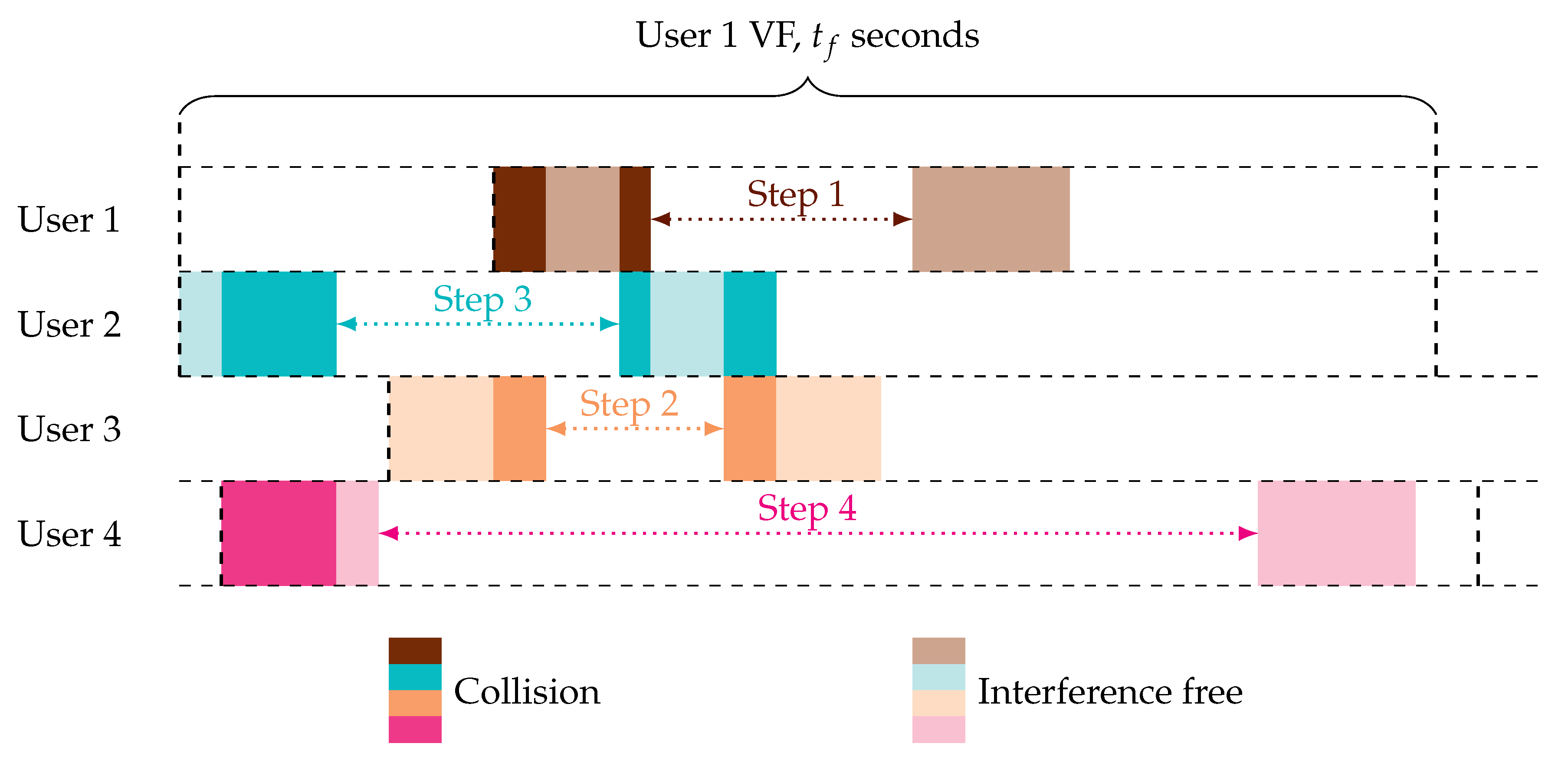
Example 1.
Consider an instance of SIC as depicted in Figure 1. A SIC step consists of successfully decoding a replica and removing it, as well as its twin from the received signal. Thus, in Figure 1, the first SIC step consists of decoding the second replica of User 1, since it is interference free. Then, the contribution of both replicas can be removed from the received signal. Consequently, the first replica of User 3 becomes interference free. We decode User 3 and remove both replicas from the signal. We proceed in the same way for User 2. Since no interference is present any more, we assume that also User 4 can be successfully decoded.
Note that replicas with the lowest level of interference are the ones with the highest chance to be correctly decoded. Interference-free replicas or replicas collided with a single interferer have the highest chance to be recovered in a SIC iteration. Considering the latter, collision of two packets yields interference, which is either at the beginning or at the end of a packet. Consequently, an error-correcting code able to better protect the beginning or the end of a packet should come to the aid of SIC improving the random access’s overall performance. In light of this, in Section 3, we focus on the design of error correcting codes able to better protect the beginning and end of a codeword.
2.2. Asynchronous Random Access Channel Model
In the following, we define the general channel model for the considered random access scheme. Assume that all replicas of all users form the set . Consider the replica in . The transmitted signal corresponding to the modulated codeword is:
where is the number of modulation symbols in a packet, is the symbol duration, and is the pulse shape. The received signal is in general affected by a frequency offset, modelled as a uniformly-distributed random variable , with the maximum frequency offset. A sampling epoch is also modelled as a uniformly distributed random variable ([37], Chapter 2). Both frequency offset and sampling epoch are common to each replica of the same user, but independently user-by-user. Furthermore, the signal is also affected by phase offset , modelled as a uniformly-distributed random variable between zero and , i.e., . Differently from the frequency offset and epoch, the phase offset is assumed to be independent replica-by-replica, i.e., may vary even among replicas of the same user. Further, we assume AWGN. No fading is considered, which is typical, e.g., for fixed-terminal geostationary orbit satellite scenarios. For , the received signal after matched filtering, which is a superposition of all replicas , is:
where is the matched filtered signal . In Equation (1), is the rth replica delay w.r.t. the common reference time. The noise term is given by , where is a white Gaussian process with single-sided power spectral density . For the sake of simplicity, throughout the paper, we make the assumptions that and , . Hence, Equation (1) becomes:
We focus again on replica r. After ideal detection, the received signal corresponding to r can be identified and isolated. Ideal channel estimation recovers perfectly the phase offset . After compensation, the discrete-time version of the received signal corresponding to the replica r is given by:
here, are the samples of a complex discrete white Gaussian process with , , . The aggregate interference contribution over the replica-r signal is , with:
here, and . The instantaneous received power for symbol i is . The useful received power is assumed to be constant over the entire replica r, i.e., for and for . For simplicity, we further assume that users are received with the same power thanks to perfect power control, i.e., for . This is a typical assumption for fixed satellite communication systems. As a result, . The aggregate interference power for symbol i is . Finally, the noise power is , and we define the signal-to-noise ratio, . We also define the signal-to-interference ratio .
3. Code Design for the Asynchronous Random Access Channel
3.1. Protograph LDPC Codes
We propose protograph-based binary LDPC code designs tailored to the interference that occurs in an asynchronous RA scenario. The parity-check matrix of these codes is derived from a relatively small matrix, called a base matrix , which represents the code constraints. Alternatively, we may describe the base matrix as a bipartite graph, termed protograph, with variable nodes (VNs) and check nodes (CNs). Non-zero entries in represent connections between VNs of type j and CNs of type i. In order to improve the code performance, we may decide to puncture some of the VN types in the base matrix whose number is denoted by . The number of not punctured variable nodes is denoted by . The parity check-matrix of a protograph-based LDPC code is obtained by expansion or lifting of the base matrix. This is done by copying the protograph times and interconnecting the copies among each other following certain rules (see [38] for details). In this work, we consider standard Gray-labelled quadrature amplitude shift keying (QPSK) modulation where the binary labels of a symbol consist of two bits. Thus, a packet with symbols is protected by an LDPC code with codeword length bits.
3.2. Code Optimization
Good base matrices are found by some optimization algorithm, such as differential evolution [39]. The goal is to find protographs that maximize a gain function. To this end, differential evolution creates a generation of candidate base matrices for which the gain function is evaluated. By introducing perturbations on the base matrix entries, a new generation of base matrices is obtained. They may replace the original ones if their gain function is higher. After a certain number of generations, we choose those base matrices that maximize the gain function.
The gain function is usually a function of the protograph ensemble’s iterative decoding threshold, which can be seen as the worst channel parameter for which symbol error probability vanishes (assuming that the block length and the number of decoding iterations go to infinity). We will give a more precise description in the following.
Iterative decoding thresholds can be found using (quantized) density evolution [15] or a suitable approximation, such as extrinsic information transfer (EXIT) analysis [40] if certain Gaussian assumptions can be made. EXIT analysis simplifies the computation of the protograph code ensemble’s compared to (quantized) differential evolution. To compute iterative decoding thresholds, we make use of the channel LLRs distributions for each codeword bit. In the following sections, we discuss the effect of the interference model on the channel LLR distributions and thus on the code design.
3.3. Simplified Channel Models for Code Design
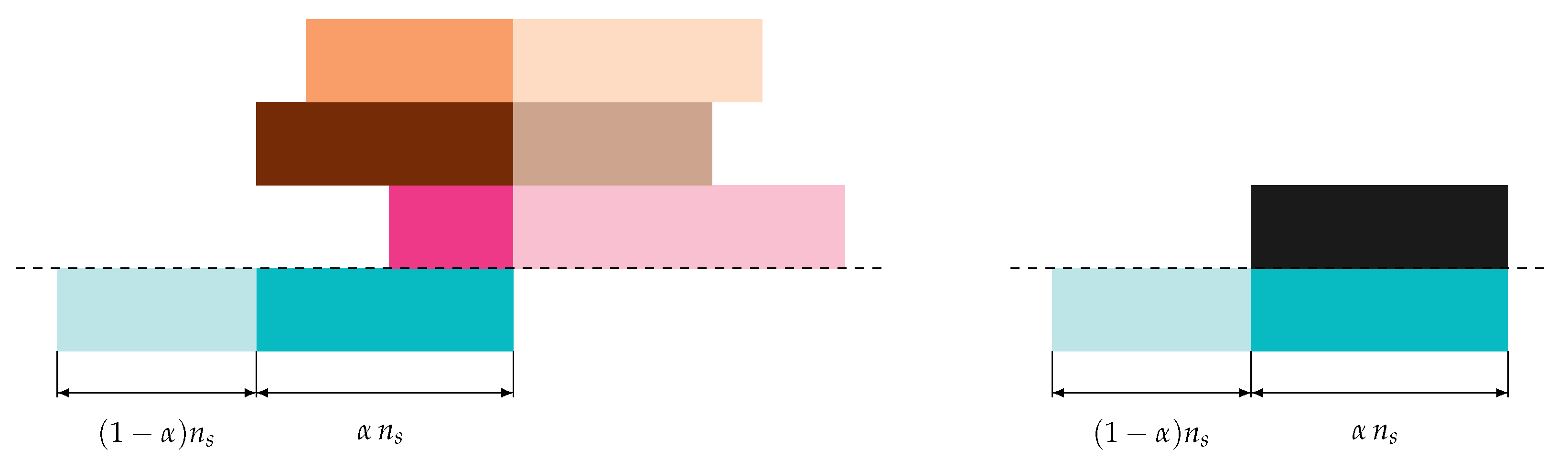
To facilitate the code design, we assume the following surrogate channel model:
- A fraction , , of a (modulated) codeword is only affected by noise with power .
- A fraction of a (modulated) codeword is affected by noise and interference of constant power over the fraction.
Thus, we make the assumption of a block interference channel [41], which is a widely-used model in the literature (see, e.g., [27] and the references therein). Clearly, this is a simplification, since a codeword in reality may experience various interference levels due to multiple packet collisions. Note also that for our asynchronous RA protocol, the interference is confined to the beginning, the end, or to the beginning and the end of a codeword. This observation is exploited for the code design. The surrogate channel model is exemplified in Figure 2. We will illustrate its validity in Section 4.
3.3.1. Gaussian Interference Model
Consider the interference vector in (2). Let its ith element be non-zero, i.e., the ith packet symbol is subject to interference. Then, is a sample of a complex Gaussian distribution , where is the interference power. This assumption is accurate already in the case of a few interferers having different phase, frequency and time offset. When only one interferer affects a packet, the assumption becomes inaccurate. Nevertheless, we will illustrate that it is a reasonable model for the LDPC code design.
Under the assumption of Gaussian interference, the interference plus noise also follows a complex Gaussian distribution , with:
Let us define as the QPSK constraint AWGN channel capacity for a given . The corresponding outage capacity for our surrogate channel model in Section 3.3 under the Gaussian interference assumption becomes:
for a fixed and , we can invert (3) and write (or likewise ) as a function of . Then, for a fixed rate, error-free transmission is possible if the interference power where is referred to as the Shannon limit.
Code design for the case of the Gaussian interference model becomes equivalent to code design for an AWGN channel where codeword bits are subjected to one of two possible noise levels. The design of LDPC photograph codes for this channel is well studied, and given that the interference is modelled as Gaussian noise, various approximations to density evolution, such as EXIT charts, are well verified in this scenario.
3.3.2. Single Interferer Model
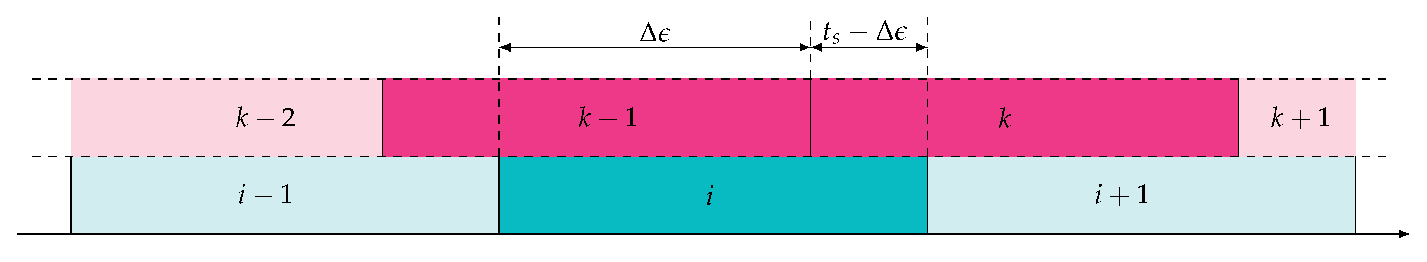
The Gaussian interference model is a reasonable approximation already in the presence of a few interferers under the assumption of time, frequency, and phase offset. When a single interferer is present over the codeword, the Gaussian model may become imprecise, and the interference shall be better characterized, taking into account the chosen modulation. Thus, in this Section, we consider a codeword affected by interference generated by a single QPSK-modulated interferer, received with the same power. After ideal detection and ideal channel estimation, the interference occurring on a codeword symbol i presents a relative phase shift and a relative epoch . Hence, the interference on codeword symbol i, i.e., , can be expressed as:
Note that . For the ease of notation, we drop the superscript , so that and . Figure 3 shows the considered scenario. The codeword symbol is interfered by a portion of symbol duration with the symbol of the interferer and by with the symbol of the interferer. We define as the set of QPSK constellation points with respective labels . For a given relative epoch and a relative phase offset , known at the receiver, the channel LLR of Bit Level 1 of a Gray-labelled QPSK signal is given by:
where we defined . For the sake of simplification, we assume symbol-synchronous interference, i.e., , and unknown, uniformly-distributed relative phase offset. We can write the the channel LLR of Bit Level 1 as:
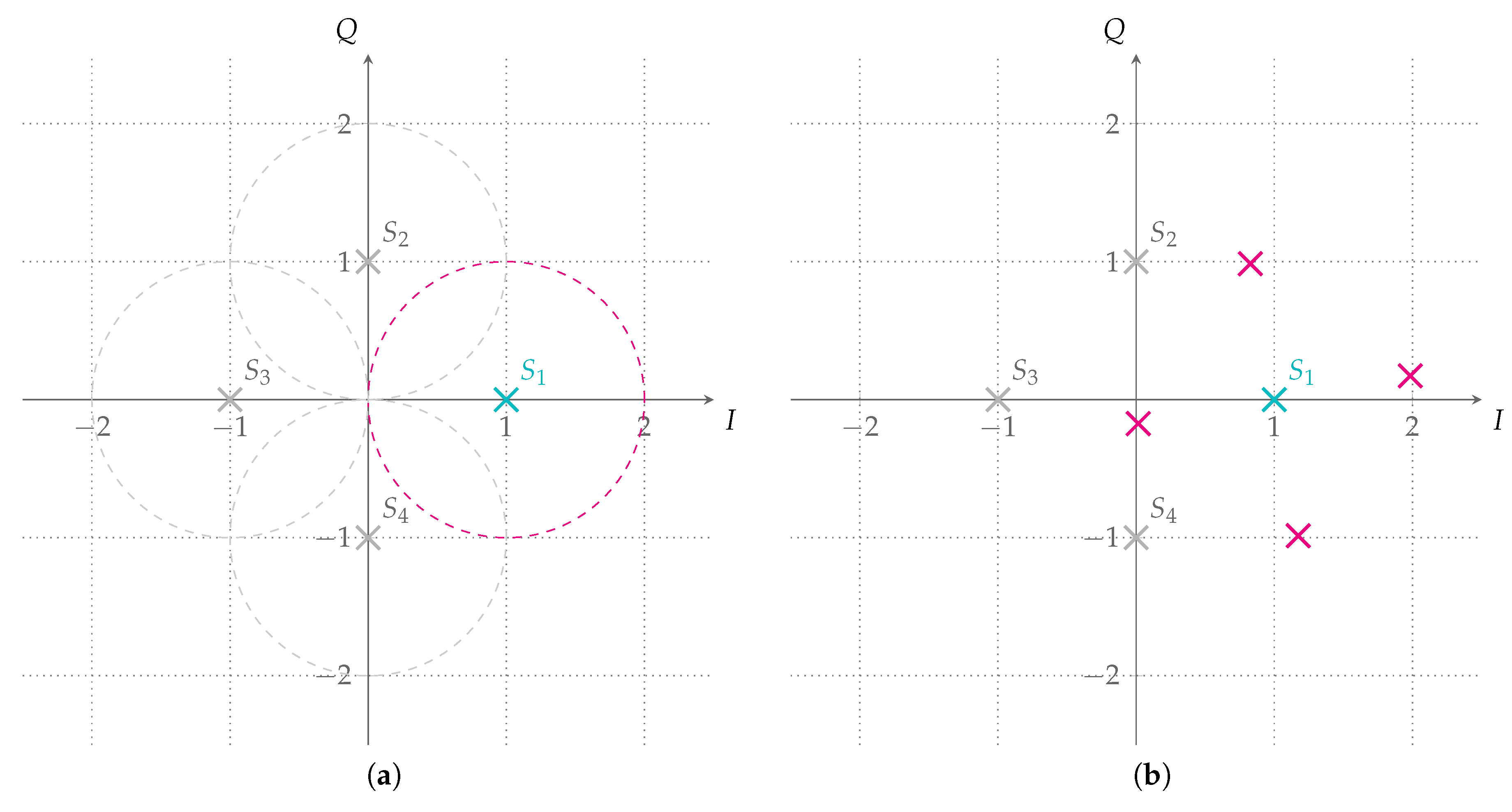
Figure 4 shows the possible received symbol i after phase compensation with no noise when symbol (or ) is transmitted. The received symbol can lay anywhere on the red circle if no assumption on interference relative phase shift is done; see Figure 4a. If a relative shift of is present, then any of the four red points can be received depending on the transmitted interference symbol k; see Figure 4b.
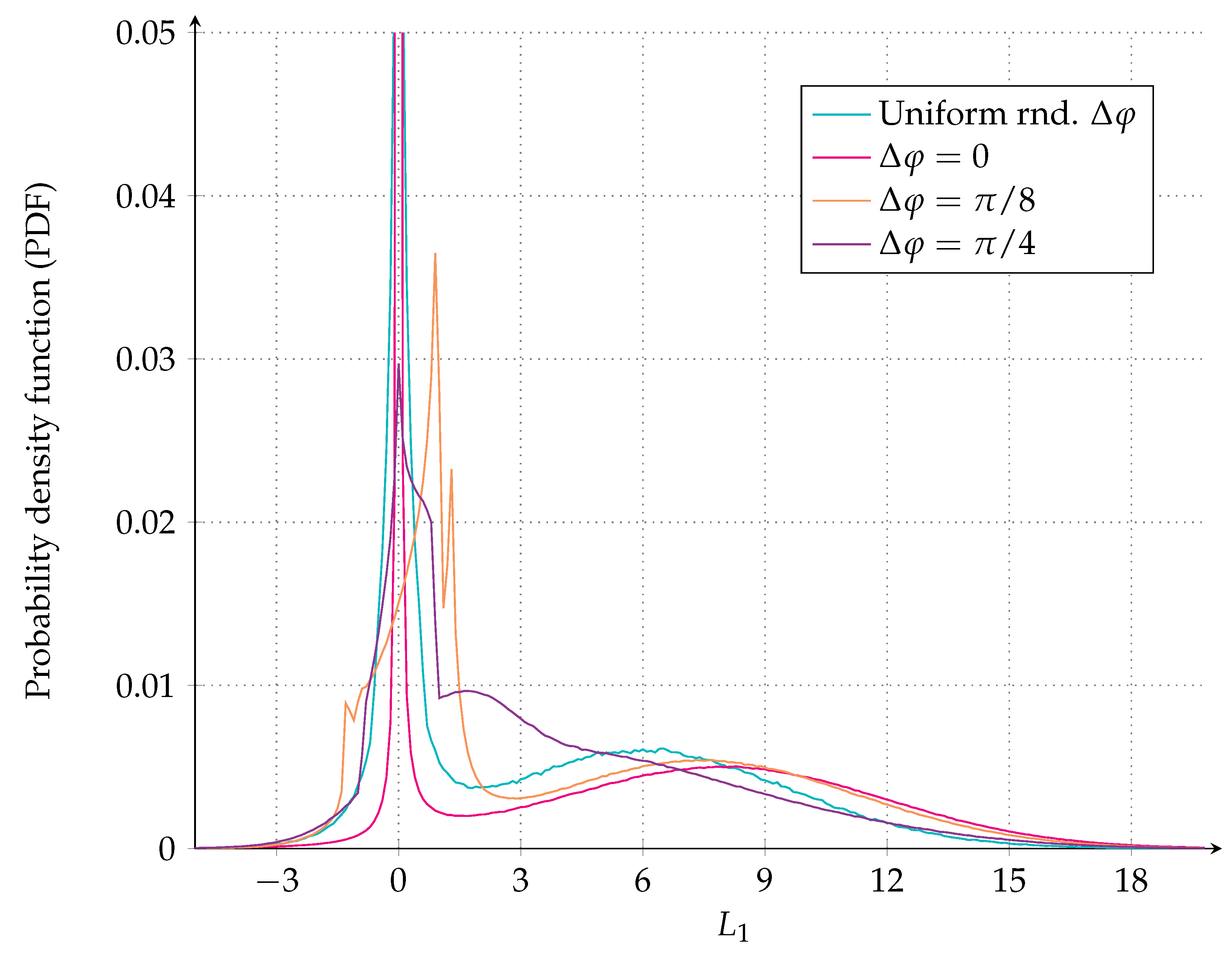
In Figure 5, the probability density function (PDF) of the bit LLRs assuming a symbol-synchronous QPSK interferer either uniform at random phase or with a fixed relative phase offset plus AWGN noise with dB is shown. For the plot, we assume that either symbol or has been transmitted, i.e., Bit level 1 is zero. The curve with shows the PDF of the bit LLRs for the case of the aligned phase. The channel LLRs are no-longer Gaussian, and thus quantized density evolution, which passes the entire LLR though the decoding algorithm, rather than a Gaussian model, will be used to calculate the code thresholds.
3.4. Code Design for Gaussian Interference
Two different code designs for the surrogate channel with Gaussian interference, as defined in Section 3.3.1, are presented next. The designs are exemplified for a code rate of , QPSK modulation and a target dB, typical parameters for an asynchronous RA scheme [25,26]. However, the code design can be easily performed for any other parameter set.
3.4.1. Ad-Hoc LDPC Code Design
Observe that the interference present in the random access channel may affect the beginning, the end, and sometimes both the beginning and end of a packet. In fact, by analysing the interference patterns, we found that the third case, where the interference affects both the beginning and end of a packet, is a case of limited interest for the code design (although it is not difficult to embed additional constraints in the code design). To see this, consider the collision of two packets. Clearly, the interference here hits the beginning or end of a packet. Consider now that three packets collide such that there exists a packet with interference both at the beginning and at the end. Then, the two remaining packets will experience a lower level of interference, which is either at the beginning or at the end. Therefore, SIC may preferably decode one of those packets and cancel their contribution from the received signal. Similar considerations can be made when four packets collide, and we have a packet with both interference at the beginning and the end. For five or more interfering packets, there could conceivably be cases where a packet with interference at both the beginning and end might be favourable to decode first, but for the code design, we focus on the most frequent cases. Thus, we tailor our code design to these specific interference patterns by targeting codes that are robust w.r.t. interference at the beginning or at the end of a codeword.
In the following, we target code designs robust to interference at the beginning or end of a codeword by imposing certain symmetry constraints on the code’s base matrix . Let us split into two submatrices, an matrix for the punctured columns and an matrix composed by all columns that are not punctured. For the entries of , we impose:
and . The symmetry requirement in (6) states that the column of from the left shall be equal to the column from the right, whose elements are however placed in a reversed order. A similar requirement is put on the submatrix .
For the protograph search by means of differential evolution, we fix , , and , such that the code rate . We also fix (e.g., as a result of link budget considerations) and look for protographs that for certain allow successful decoding at an interference power as high as possible. Thus, the iterative decoding threshold is the maximum interference power for a certain and , such that the probability of symbol error in a codeword vanishes. Since is the outcome of a random process, we are interested in a code design that is robust for various values of , denoted by . This implies a multi-target optimization. Due to complexity reasons, we resort to only a few different for which we simultaneously optimize our base matrices.
The Gaussian interference model yields channel LLRs for the two QPSK bit levels that are Gaussian distributed. For this setup, EXIT analysis [40] is known to provide accurate iterative decoding threshold estimates. Thus, for each , we aim at determining the maximum amount of interference , such that error-free decoding is possible. Following the results in [40], this requires that the log-likelihood a posteriori probability (APP) mutual information (assuming that the block length and the number of decoding iterations go to infinity).
For a general code ensemble, the computation of the iterative decoding threshold has to take into account the respective cases of the interferer being at the beginning or end of the codeword. Let us denote by and by the iterative decoding threshold for a chosen , when the interferer affects the beginning or end of the codeword, respectively. We evaluate the following gain function g,
where is obtained from the outage capacity expression in (3). Note that due to the symmetry constraint in (6), and (7) can be simplified.
Example 2.
Fix , , , , where the first column is punctured. For the multi-target optimization, we impose the symmetry constraint in (6). For complexity reasons, we optimize the threshold for only two different values of α, namely and . The differential evolution algorithm in [39] was executed with the following parameters: crossover probability of , population size of 200, and number of generations of 4000. The multi-target optimization yields:
3.4.2. Raptor-Like LDPC Code Design
Protograph-based Raptor-like LDPC codes [42] belong to the class of rate-compatible LDPC codes. The base matrix has the following structure:
where in analogy to Raptor codes, and represent the base matrices of the precode and Luby transform (LT) code, respectively. Further, is an identity matrix. Owing to their excellent performance, protograph-based Raptor-like LDPC codes are adapted in the context of the 5G standardization for enhanced mobile broadband (eMBB). During the standardization, several proposals for base matrices have been made with very similar performance. We consider one of these 5G proposals for short blocks [43]
where the first two VNs are punctured. The motivation for this choice is to illustrate that 5G eMBB codes might be suitable candidates for RA applications.
The base matrix in (8) is not tailored to the specific interference patterns that occur for our asynchronous RA protocol. Recall that for our code design, we consider interference that is confined to the beginning or end of a codeword. To improve the iterative decoding threshold for the base matrix in (8), we may permute its columns such that the gain function in (7) is maximized. We evaluate the gain function for two different , i.e., and .
Note that there exist permutations for the base matrix (ignoring the punctured columns). To reduce the number of permutations to test, we group VNs together based on their degrees with the intuition that placing a VN from a certain group at a position in the protograph will yield a comparable value of the gain function. Therefore, the total number of different permutations to be tested reduces to 4200. The permutation vector yielding the highest value of the gain function is:
We denote the resulting permuted base matrix by .
3.4.3. Asymptotic Results for Gaussian Interference
In Figure 6, we depict iterative decoding thresholds versus on the surrogate channel with Gaussian interference for the code ensembles with base matrices , and . In all three cases, the design rate and dB. We provide thresholds for the cases when the interferer is at the beginning or at the end of a packet. As a reference, we also show versus from the outage capacity expression in (3).
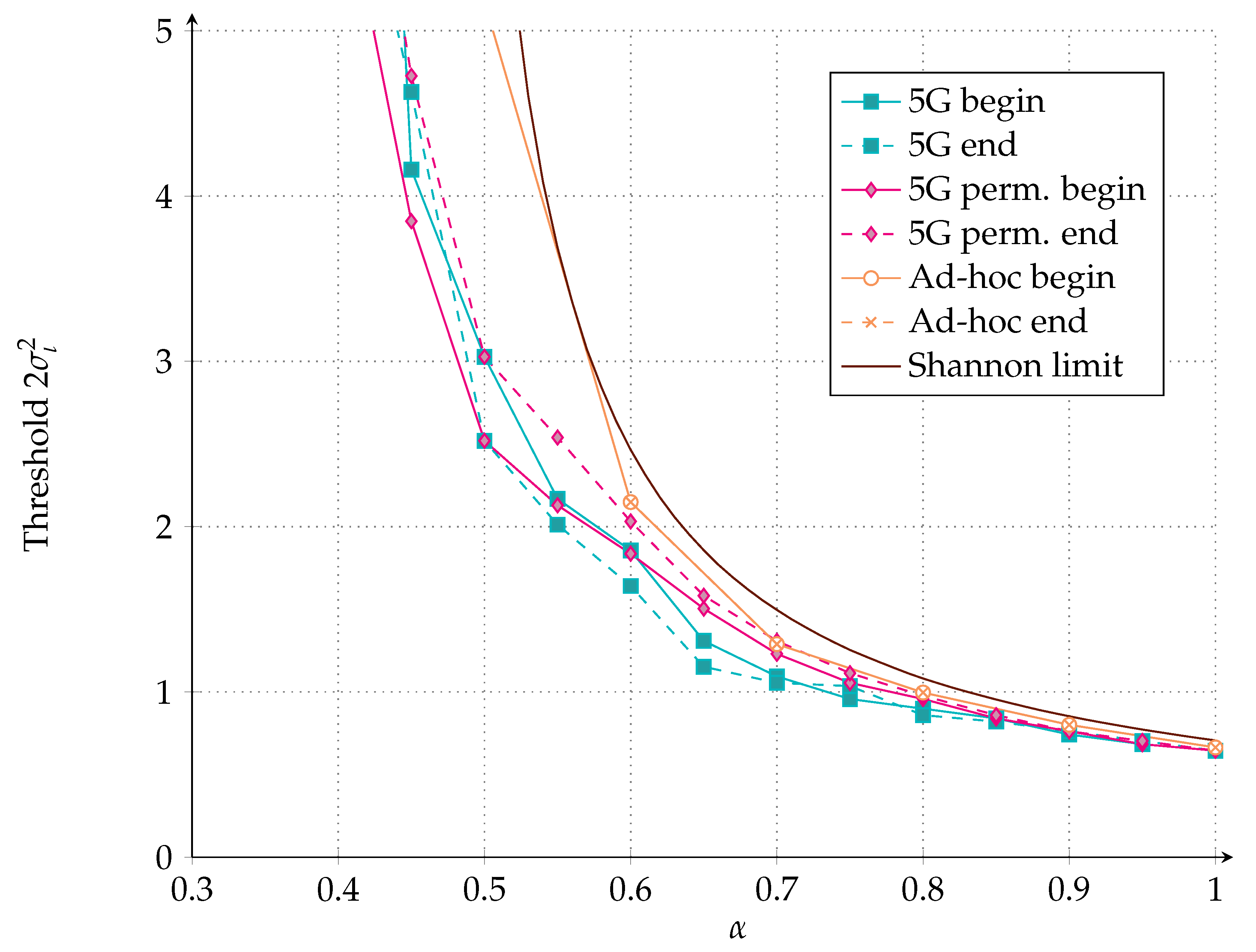
Observe from the figure that the ad-hoc code design (base matrix ) performs close to the capacity curve. Furthermore, owing to the symmetry constraint in (6), the code ensemble shows the same behaviour for the interference being at the beginning or at the end of a codeword. The 5G-like protograph code ensemble (base matrix ) performs differently if the interferer is from the left or right. By permuting the code (base matrix ) as described in Section 3.4.2, the code ensemble performance gets closer to capacity. Further, for close to one, both 5G-like and ad-hoc code design perform similarly. This is because here, the channel is like a conventional AWGN channel for which 5G codes are known to be among the best LDPC codes.
3.5. Asymptotic Results for a Single Non-Gaussian Interferer
Although our ad-hoc protograph ensemble was designed for the Gaussian interference model, we show here that its asymptotic performance is also good in this case of non-Gaussian interferers. We consider the iterative decoding threshold of our ad-hoc protograph ensemble for two cases:
- Symbol-synchronous, phase-aligned, equal-power QPSK interferer, i.e., , , .
- Symbol-synchronous, equal-power QPSK interferer uniform at random phase, i.e., , , .
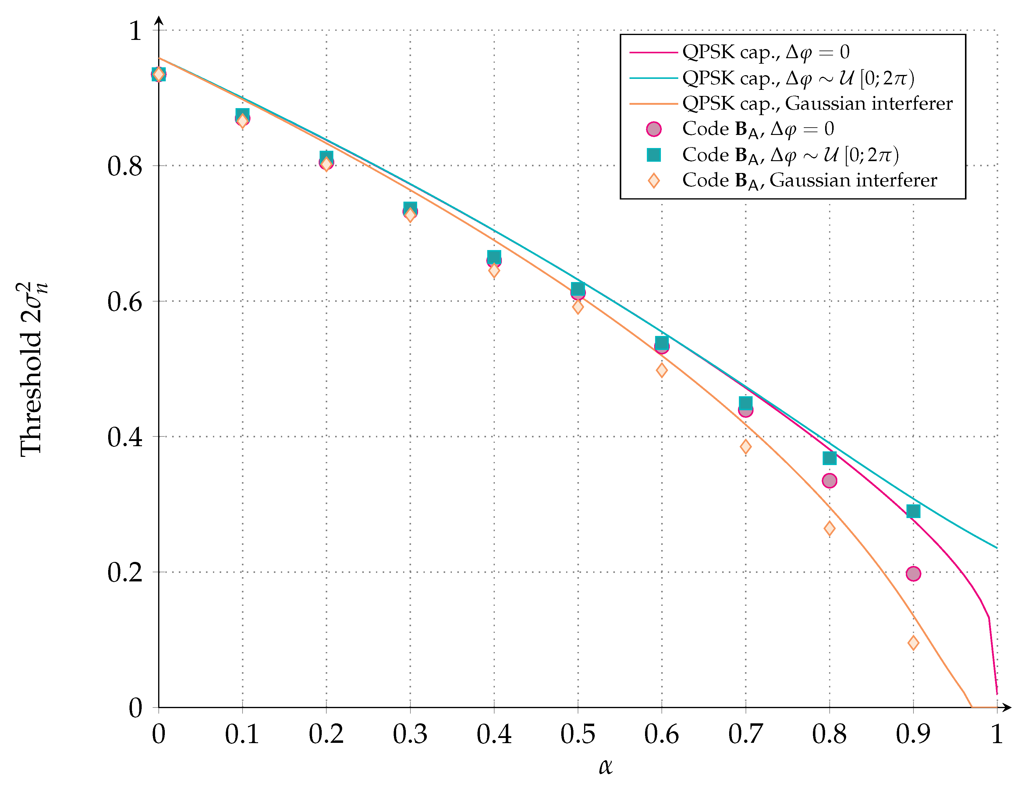
For reference, we also show the results for a single equal-power interferer if that interferer is assumed to be Gaussian. We determine the iterative decoding threshold of our ad-hoc protograph ensemble for these interference models by applying (quantized) density evolution, making use of Equations (4) and (5). Since the interferer power is fixed, we define the iterative decoding threshold as the largest noise power per dimension such that error-free transmission is possible. Figure 7 shows the density evolution threshold of the ad-hoc protograph ensemble compared to the channel capacity in each of the three interferer models.
As shown in Figure 7, the QPSK interferer with random phase gives the best threshold, whereas the Gaussian interferer gives the worst threshold. We can explain this by using Figure 4. In the absence of noise, the received signal is on a circle around the transmitted signal, . To depict , we can simply draw four circles around the four QPSK constellation points. It can be observed that these circles intersect. However, the probability to pick exactly the intersection point goes to zero. Thus, we can reach a mutual information of two for the QPSK interferer with random phase. For the phase-aligned QPSK interferer, the mutual information between and reaches one in the absence of noise. Thus, for the interfered part, we can get a rate of at most one. Hence, the phase-aligned QPSK interferer gives a lower threshold than the QPSK interferer with random phase. For the Gaussian interferer case, the mutual information is limited by the QPSK capacity at dB, where the mutual information at 0 dB is 0.96 for the interfered part. Thus, the Gaussian interference model shows the worst threshold compared to the phase-aligned QPSK interferer and QPSK interferer with random phase.
4. Numerical Results
For the numerical results, we drop the simplified surrogate channel model and focus on two more realistic RA channels. The first set of numerical results makes use of a physical layer abstraction where the interference is Gaussian, but not necessarily constant over the symbols of a modulated codeword. In the second set of numerical results, the complete physical layer is implemented, and hence, the Gaussian assumption on the interference is dropped. While the abstracted physical layer model is a common approach to get first-level insights into the system performance [27], (long) physical layer simulations serve as a confirmation of the results. If the identified trends are still present, physical layer results may give evidence of the validity of the surrogate channel model adopted for the code design.
The assumptions common to both sets of numerical results are summarized in the following. Users transmit replicas according to the asynchronous RA protocol described in Section 2.1. Replicas are affected by multiple access interference and by AWGN noise, with dB. All replicas are received with the same normalized power , thanks to perfect power control. For simplicity, we normalized all durations to the packet length . The VF duration was set to , while the receiver decoding window was . The receiver decoding window shift was set to .
The performance metric we used to compare the performance of different error correcting codes in the asynchronous random access setting is the PLR , as a function of the channel load . The PLR is the average probability that a user cannot be correctly recovered at the receiver, at the end of the SIC process.
4.1. Abstracted Physical Layer
To abstract the physical layer, we made use of so-called decoding regions [44]. Based on a certain interference pattern, we decided whether the decoding of a replica was successful or not, simply by checking whether the corresponding noise plus interference vector fell within the decoding region. An m-dimensional decoding region can be seen as an extension of a threshold model to channels with m-dimensional channel parameters, such as block fading channels.
4.1.1. Decoding Region for Random Code Ensembles
We assumed that replicas are received with interference whose power may vary over the replica symbols. We resorted to a block interference channel [41], where a replica experiences various blocks of constant interference. Recall that the interference was assumed to be drawn from a complex white Gaussian process , with being the interference power (see also Section 3.3.1).
Let us call the maximum number of interferers affecting a replica. Let us denote by m, , the number of different interference plus noise levels that are present over the considered replica. Define:
as the ordered interference plus noise vector, which contains the m different noise plus interference levels in the replica. Let , where , , is the fraction of a replica subject to the interference plus noise of power per dimension. Clearly, and . Recalling that is the QPSK constraint AWGN channel capacity for a given , the outage capacity under the Gaussian interference assumption is:
For a fixed transmission rate , we define the decoding region [33,44] as:
Every -user collision resulting in can be resolved.
A possibility to evaluate numerically the performance of a random code ensemble that achieves a fraction of the outage capacity with , is to compute the decoding region as:
For the abstracted physical layer simulations, we followed the steps from the literature [44]. We generated realizations of packet collisions for a certain channel load . For each of the codeword symbols of a replica, we computed an instantaneous noise plus interference power. We assumed that for each codeword symbol, we had knowledge of the number of interferers due to ideal detection. Thus, we grouped the instantaneous noise plus interference power values into m blocks, sorted them according to the number of interferers, and averaged over the noise plus interference power in every block to finally obtain the ordered interference plus noise vector in (9). Successful decoding was declared if (or ).
4.1.2. Decoding Region for LDPC Code Ensembles
For LDPC protograph ensembles, the decoding region was computed slightly differently from (10). Since for structured code ensembles, not only the power and fraction, but also the position of the interferer are important, we introduced a length- protograph noise plus interference vector . An element corresponds to the specific signal plus interference level for a VN of type j. Then, the decoding region in (10) can be restated as:
The signal plus interference level for a VN of type j is determined as follows. For a certain channel load , realizations of packet collisions are generated. For each of them, one may determine an instantaneous bit-wise noise plus interference power for each of the n codeword bits. Then, for each of the unpunctured VN types in the protograph, we determine an average noise plus interference level by averaging over subsequent values of the instantaneous bit-wise noise plus interference powers, yielding . Decoding is successful only if .
4.1.3. Simulation Results
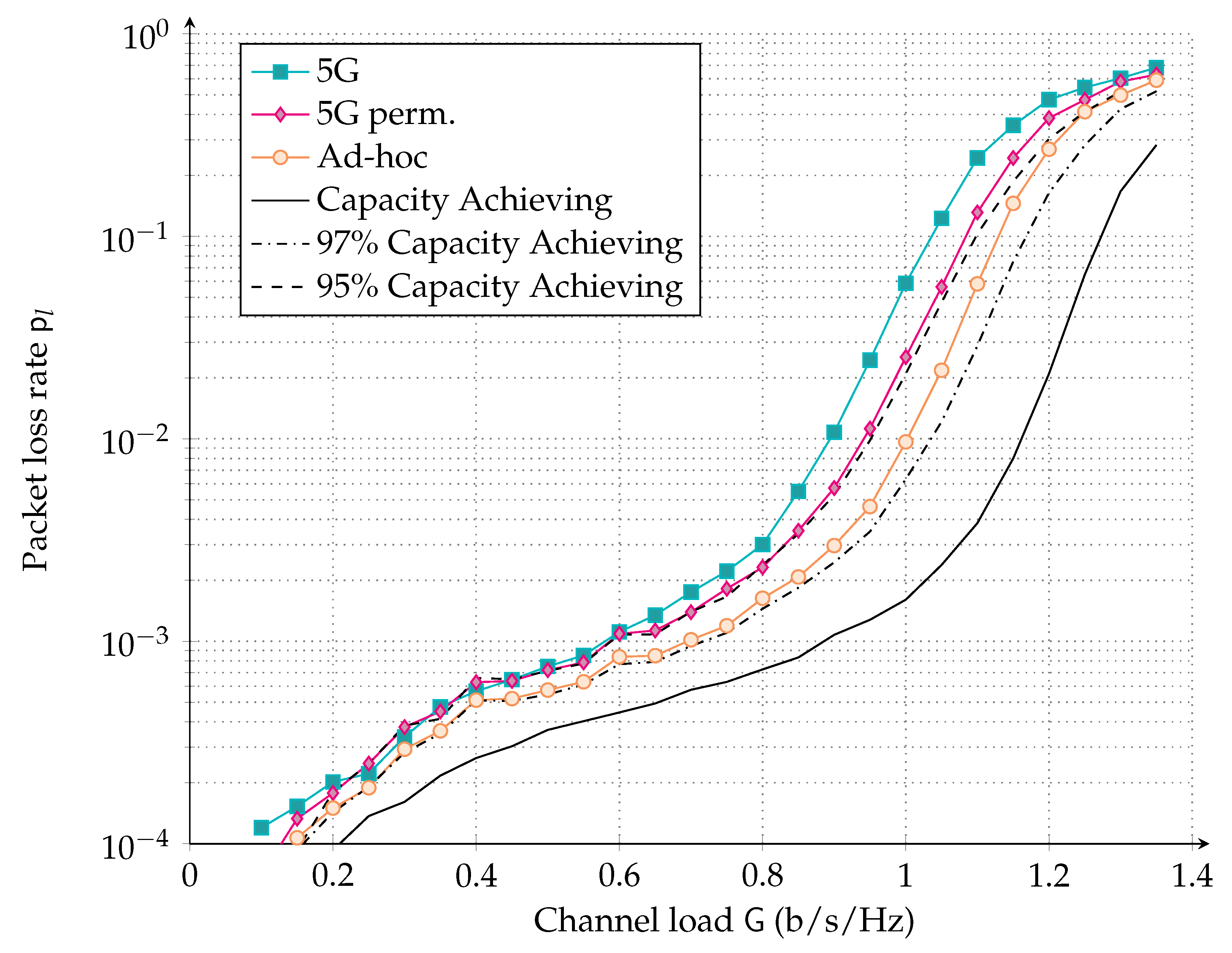
The PLR performance assuming the three different protograph code ensembles from Section 3.4 is shown in Figure 8. For reference, the performance for a capacity achieving code ensemble, one that achieves of capacity and one that achieves of capacity, is also shown (solid black, dot-dashed black and dashed black curves, respectively). In the entire channel load range, the ad-hoc design (base matrix ) visibly outperformed both 5G-based solutions (base matrices and ). The simple yet insightful observation that the beginning and the end of a packet shall be strongly protected by the channel code led to a beneficial performance gain also when the overall multiple access interference comes into play. In particular, for a target PLR of , the channel load supported can be extended from b/s/Hz of the 5G-based solutions to b/s/Hz of the ad-hoc LDPC design, resulting in a b/s/Hz or gain. Similarly, at PLR of , the channel load supported can be extended from b/s/Hz of the 5G-based solutions to b/s/Hz of the ad-hoc LDPC design, resulting in a b/s/Hz or gain. For a fixed channel load operating point, the gain was even more remarkable.
Finally, observe that there is still a visible gap to capacity achieving code ensembles. One may erroneously conclude that the constant interfering power assumption of the surrogate channel model in Section 3.3 is inaccurate, yielding a design that is penalized on the Gaussian interference channel with varying interference powers. However, we found that even a small loss in error correction performance may have a big effect on the PLR. To underpin this observation, consider a code ensemble that achieves of the outage capacity. Observe that this code ensemble performs similarly to the permuted 5G-like design and worse than our ad-hoc design for the surrogate channel. A possible reason for the drastic impact of the code performance on the asynchronous random access PLR might be due to the SIC: in the case that a replica cannot be correctly decoded due to the sub-optimality of the error correcting code, it may arrest the SIC process and cause multiple packet losses. Consider a code ensemble that achieves of the outage capacity instead of . Observe from the figure that such a minor improvement on the code design can result in gains of up to b/s/Hz.
In order to confirm the trends identified with the abstracted physical layer and to overcome its inherent limitations, in the following Section we will resort to simulate the physical layer performance of the proposed LDPC codes.
4.2. Finite-Length Physical Layer Simulations with the Designed LDPC Codes
We consider here LDPC codes obtained from the base matrices in Section 3.4. The code parameters were chosen to fit in the context of short packet communications. Packets in the order of hundreds of information bits are typical of M2M applications. An example is the early data transmission procedure available in Release 15 of 3GPP, where terminals are allowed to piggyback data on Message 3 of the PRACH with sizes between 328 and 1000 information bits [2]. Each user selects a codeword uniformly at random from the codebook. The codeword is QPSK modulated, and two instances (replicas) are transmitted. Each of the modulated replicas are sent over the asynchronous RA channel undergoing the protocol rules as described in Section 2. Ideal channel estimation is assumed, so that the receiver can perfectly compensate for the phase offset. After channel estimation, soft-LLR values are computed based on the perfect interference power knowledge. Note that the interference contribution here is the superposition of possibly multiple QPSK-modulated, equal-power signals, with random phase offsets, corresponding to all replicas that are concurrently received. It is important to stress that this assumption departs from the Gaussian interference assumption, especially when the number of interfering replicas is small. A standard belief propagation LDPC decoder with a maximum of 50 decoding iterations is used to counteract the effect of noise and multiple access interference. If the decoder is successful, the replica is removed from the received signal together with its twin, so that no residual interference power is left after cancellation.
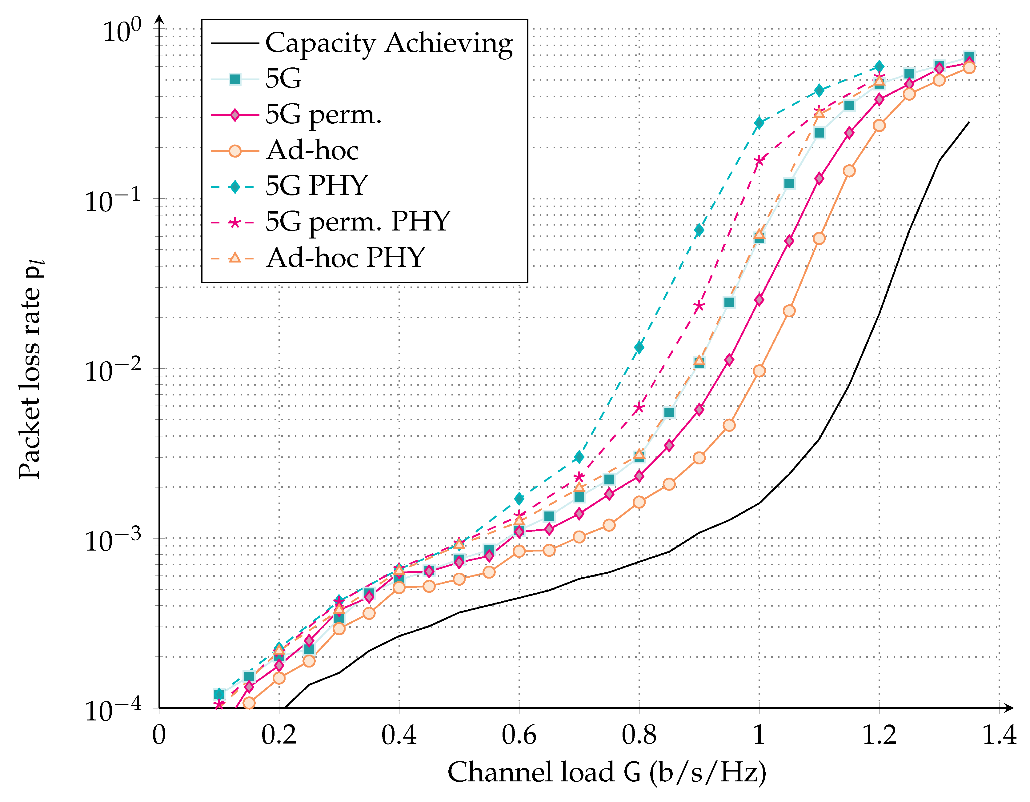
The dashed curves in Figure 9 show the PLR performance versus channel load of the asynchronous RA scheme with replicas protected with a code described by the base matrix (named ad-hoc PHY), (named 5G perm. PHY), or (named 5G PHY), respectively. The solid curves are resumed from Figure 8 and depict results for the abstracted physical layer. Observe that the relative gap between the ad-hoc LDPC design, permuted 5G design, as well as the 5G design was preserved, since all three codes suffered from a similar degradation due to finite length effects. For the ad-hoc design, at a target PLR of , the supported channel load was reduced from b/s/Hz to b/s/Hz. Similarly, at , the achieved channel load became b/s/Hz compared to 1 b/s/Hz when the abstract physical layer was considered. In line with the ad-hoc design, also the 5G code suffered from a degradation of b/s/Hz in the channel load region of interest.
Interestingly, although the ad-hoc LDPC code was designed for a surrogate channel, both the abstract physical layer and the full physical layer simulations confirmed the beneficial impact on the asynchronous random access protocol. The abstract physical layer model was able to hinge the performance tendencies that were subject to a penalty when one considers the precise physical layer. Such penalty mostly originated from finite-length effects of the channel code. The assumption of Gaussianity for the multiple access interference, as well as constant interfering power appeared to be reasonable and thus can be exploited to simplify the channel code design.
5. Conclusions
This work presented protograph LDPC code designs for asynchronous RA with SIC. For the code design, we made use of a simplified surrogate channel model that assumed Gaussian interference and constant interfering power over the interfered part of a packet. Considering more realistic RA channels, we showed that the proposed designs for the surrogate channel performed close to theoretical limits. Gains of 17%, in the supported channel load at a packet loss rate of , were observed w.r.t. an off-the-shelf code. In contrast to literature where the physical layer code performance is often abstracted by means of decoding thresholds or decoding regions, physical layer LDPC code simulations for short blocks were performed, yielding a more realistic estimate of the achievable supported channel load (for a fixed target packet error rate). We found that abstracting the physical layer overestimated the performance for our setup by approximately 10% in the supported channel load, at a packet loss rate of .
Author Contributions
Conceptualization, F.C., B.M. and S.J.J.; methodology, M.S. and S.J.J.; software, F.C.; validation, F.C., B.M. and S.J.; formal analysis, F.C. and B.M.; investigation, F.C., B.M., S.J., M.S. and S.J.J.; writing–original draft preparation, F.C., B.M., S.J., M.S. and S.J.J.; writing–review and editing, F.C., B.M.; visualization, F.C.; supervision, F.C. and B.M.
Funding
This research was partially funded by the German Academic Exchange Service (DAAD) PPP Australien 2017 grant number 57319586 and by the Universities Australia (UA) grant number GJRCS17 for the project Ultra-Low Latency Communication Strategies for Machine-to-Machine Communications.
Acknowledgments
The authors would like to thank Nina Grosheva for her support in the design of the asynchronous medium access simulation environment during its early stages.
Conflicts of Interest
The authors declare no conflict of interest.
Acronyms
The following abbreviations are used in this manuscript:
| 5G | fifth generation of mobile networks |
| ACRDA | asynchronous contention resolution diversity ALOHA |
| APP | a posteriori probability |
| ARA | accumulate repeat accumulate |
| AWGN | additive white Gaussian noise |
| CDF | cumulative distribution function |
| CN | check node |
| CRA | contention resolution ALOHA |
| CRC | cyclic redundancy check |
| CRDSA | contention resolution diversity slotted ALOHA |
| CSA | coded slotted ALOHA |
| DAMA | demand assigned multiple access |
| DSA | diversity slotted ALOHA |
| ECRA | enhanced contention resolution ALOHA |
| eMBB | enhanced mobile broadband |
| EXIT | extrinsic information transfer |
| FEC | forward error correction |
| GEO | geostationary orbit |
| IC | interference cancellation |
| IRCRA | irregular repetition contention resolution ALOHA |
| IRSA | irregular repetition slotted ALOHA |
| LDPC | low-density parity-check |
| LLR | log-likelihood ratio |
| LT | Luby transform |
| M2M | machine-to-machine |
| MAC | medium access |
| MF | matched filter |
| MF-TDMA | multi-frequency time division multiple access |
| MRC | maximal-ratio combining |
| mMTC | massive machine-type communications |
| probability density function | |
| PER | packet error rate |
| PLR | packet loss rate |
| PRACH | physical random access channel |
| QPSK | quadrature amplitude shift keying |
| RA | random access |
| RV | random variable |
| SA | slotted ALOHA |
| SB | Shannon bound |
| SC | selection combining |
| SIC | successive interference cancellation |
| SINR | signal-to-interference and noise ratio |
| SNIR | signal-to-noise-plus-interference ratio |
| SNR | signal-to-noise ratio |
| TDMA | time division multiple access |
| TS | time sharing |
| VF | virtual frame |
| VN | variable node |
| WER | word error rate |
References
- Osseiran, A.; Boccardi, F.; Braun, V.; Kusume, K.; Marsch, P.; Maternia, M.; Queseth, O.; Schellmann, M.; Schotten, H.; Taoka, H.; et al. Scenario for 5G mobile and wireless communications: The vision of the METIS project. IEEE Commun. Mag. 2014, 52, 26–35. [Google Scholar] [CrossRef]
- 3GPP. TR 21.915 v1.1.0, Release 15 Description. 2019. Available online: https://www.3gpp.org/DynaReport/21-series.htm (accessed on 14 August 2019).
- Laya, A.; Alonso, L.; Alonso-Zarate, J. Is the Random Access Channel of LTE and LTE-A Suitable for M2M Communications? A Survey of Alternatives. IEEE Commun. Surv. Tutor. 2014, 16, 4–16. [Google Scholar] [CrossRef]
- Abramson, N. The ALOHA system: Another alternative for computer communications. In Proceedings of the Fall Joint Computer Conference (AFIPS), Houston, Texas, 17–19 November 1970; ACM: New York, NY, USA, 1970; Volume 37, pp. 281–285. [Google Scholar]
- Roberts, L.G. ALOHA packet system with and without slots and capture. Proc. SIGCOMM Comput. Commun. Rev. 1975, 5, 28–42. [Google Scholar] [CrossRef]
- Casini, E.; De Gaudenzi, R.; Del Rio Herrero, O. Contention resolution diversity slotted ALOHA (CRDSA): An enhanced random access scheme for satellite access packet networks. IEEE Trans. Wirel. Commun. 2007, 6, 1408–1419. [Google Scholar] [CrossRef]
- Liva, G. Graph-Based Analysis and Optimization of Contention Resolution Diversity Slotted ALOHA. IEEE Trans. Commun. 2011, 59, 477–487. [Google Scholar] [CrossRef]
- Paolini, E.; Liva, G.; Chiani, M. Coded Slotted ALOHA: A Graph-Based Method for Uncoordinated Multiple Access. IEEE Trans. Inf. Theory 2015, 61, 6815–6832. [Google Scholar] [CrossRef] [Green Version]
- Sandgren, E.; i Amat, A.G.; Brännström, F. On Frame Asynchronous Coded Slotted ALOHA: Asymptotic, Finite Length, and Delay Analysis. IEEE Trans. Commun. 2017, 65, 691–703. [Google Scholar] [CrossRef]
- Stefanovic, C.; Popovski, P. ALOHA Random Access that Operates as a Rateless Code. IEEE Trans. Commun. 2013, 61, 4653–4662. [Google Scholar] [CrossRef] [Green Version]
- Yu, Y.; Giannakis, G.B. High-Throughput Random Access Using Successive Interference Cancellation in a Tree Algorithm. IEEE Trans. Inf. Theory 2007, 53, 4628–4639. [Google Scholar] [CrossRef]
- Massey, J.L. Collision-Resolution Algorithm and Random-Access Communication. In Multi-User Communication Systems; Longo, G., Ed.; Springer: Vienna, Austria, 1981; pp. 73–137. [Google Scholar]
- Gallager, R. A perspective on Multiaccess Channels. IEEE Trans. Inf. Theory 1985, 31, 124–142. [Google Scholar] [CrossRef]
- Luby, M.; Mitzenmacher, M.; Shokrollahi, A.; Spielman, D.A. Improved Low-Density Parity-Check Codes Using Irregular Graphs. IEEE Trans. Inf. Theory 2001, 47, 585–598. [Google Scholar] [CrossRef]
- Richardson, T.J.; Shokrollahi, A.; Urbanke, R.L. Design of Capacity-Approaching Irregular Low-Density Parity-Check Codes. IEEE Trans. Inf. Theory 2001, 47, 619–637. [Google Scholar] [CrossRef]
- Ivanov, M.; Brännström, F.; i Amat, A.G.; Popovski, P. Error Floor Analysis of Coded Slotted ALOHA Over Packet Erasure Channels. IEEE Commun. Lett. 2015, 19, 419–422. [Google Scholar] [CrossRef]
- i Amat, A.G.; Liva, G. Finite-Length Analysis of Irregular Repetition Slotted ALOHA in the Waterfall Region. IEEE Commun. Lett. 2018, 22, 886–889. [Google Scholar] [CrossRef] [Green Version]
- Narayanan, K.R.; Pfister, H.D. Iterative Collision Resolution for Slotted ALOHA: An Optimal Uncoordinated Transmission Policy. In Proceedings of the 7th International Symposium on Turbo Codes and Iterative Information Processing (ISTC), Gothenburg, Sweden, 27–31 August 2012; pp. 136–139. [Google Scholar]
- Polyanskiy, Y. A Perspecitve on Massive Random-Access. In Proceedings of the 2017 IEEE International Symposium on Information Theory (ISIT), Aachen, Germany, 25–30 June 2017; pp. 2523–2527. [Google Scholar]
- Effros, M.; Kostina, V.; Yavas, R.C. Random Access Channel Coding in the Finite Blocklength Regime. In Proceedings of the 2018 IEEE International Symposium on Information Theory (ISIT), Vail, CO, USA, 17–22 June 2018. [Google Scholar]
- Ordentlich, O.; Polyanskiy, Y. Low Complexity Scheme for the Random Access Gaussian Channel. In Proceedings of the 2017 IEEE International Symposium on Information Theory (ISIT), Aachen, Germany, 25–30 June 2017; pp. 2528–2532. [Google Scholar]
- Vem, A.; Narayanan, K.R.; Cheng, J.; Chamberland, J.F. A User-Indipendent Serial Interference Cancellation Based Coding Scheme for the Unsourced Random Access Gaussian Channel. In Proceedings of the 2017 IEEE Information Theory Workshop (ITW), Kaohsiung, Taiwan, 6–10 November 2017; pp. 121–125. [Google Scholar]
- Calderbank, R.; Thompson, A. CHIRRUP: A Practical Algorithm for Unsourced Multiple Access. arXiv 2018, arXiv:1811.00879. [Google Scholar]
- Amalladinne, V.K.; Chamberland, J.F.; Narayanan, K.R. A Coded Compressed Sensing Scheme for Uncoordinated Multiple Access. arXiv 2018, arXiv:1809.04745. [Google Scholar]
- Kissling, C. Performance Enhancements for Asynchronous Random Access Protocols over Satellite. In Proceedings of the 2011 IEEE International Conference on Communications (ICC), Kyoto, Japan, 5–9 June 2011; pp. 1–6. [Google Scholar]
- De Gaudenzi, R.; del Rio Herrero, O.; Acar, G.; Barrabes, E.G. Asynchronous Contention Resolution Diversity ALOHA: Making CRDSA Truly Asynchronous. IEEE Trans. Wirel. Commun. 2014, 13, 6193–6206. [Google Scholar] [CrossRef]
- Clazzer, F.; Kissling, C.; Marchese, M. Enhancing Contention Resolution ALOHA using Combining Techniques. IEEE Trans. Commun. 2018, 66, 2576–2587. [Google Scholar] [CrossRef]
- Akyildiz, T.; Demirhan, U.; Duman, T.M. Asymptotic Analysis of Contention Resolution ALOHA with Replica Concatenation. In Proceedings of the 2019 IEEE International Conference on Communications (ICC), Shanghai, China, 20–24 May 2019; pp. 1–6. [Google Scholar]
- Kissling, C.; Clazzer, F. LDPC code performance and optimum code rate for Contention Resolution Diversity ALOHA. In Proceedings of the IEEE Global Communications Conference (GLOBECOM), Atlanta, GA, USA, 9–13 December 2013; pp. 2932–2938. [Google Scholar]
- Matuz, B.; Clazzer, F.; Johnson, S.J.; Jayasooriya, S.; Shirvanimoghaddam, M. LDPC Code Design for Asynchronous Random Access. In Proceedings of the 2018 IEEE 10th International Symposium on Turbo Codes Iterative Information Processing (ISTC), Hong Kong, China, 3–7 December 2018; pp. 1–5. [Google Scholar]
- Masnick, B.; Wolf, J. On linear unequal error protection codes. IEEE Trans. Inf. Theory 1967, 13, 600–607. [Google Scholar] [CrossRef]
- Caire, G.; Biglieri, E. Parallel Concatenated Codes with Unequal Error Protection. IEEE Trans. Commun. 1998, 46, 565–567. [Google Scholar] [CrossRef]
- Boutros, J.J.; i Fabregas, A.G.; Calvanese, E. Analysis of Coding on Non-Ergodic Block fading Channels. In Proceedings of the 2005 Allerton Conference on Communication, Control and Computing, Monticello, IL, USA, 28–30 September 2005. [Google Scholar]
- Boutros, J.J.; i Fabregas, A.G.; Biglieri, E.; Zemor, G. Low-Density Parity-Check Codes for Nonergodic Block-Fading Channels. IEEE Trans. Inf. Theory 2010, 56, 4286–4300. [Google Scholar] [CrossRef] [Green Version]
- Chiani, M. Noncoherent Frame Synchronization. IEEE Trans. Commun. 2010, 58, 1536–1545. [Google Scholar] [CrossRef]
- Clazzer, F.; Lázaro, F.; Liva, G.; Marchese, M. Detection and Combining Techniques for Asynchronous Random Access with Time Diversity. In Proceedings of the 11th International ITG Conference on Systems, Communications and Coding (SCC), Hamburg, Germany, 6–9 February 2017; pp. 1–6. [Google Scholar]
- Mengali, U.; D’Andrea, A.N. Synchronization Techniques for Digital Receivers; Springer Science+Business Media: Berlin, Germany, 1997. [Google Scholar]
- Thorpe, J. Low-Density Parity-Check (LDPC) Codes Constructed from Protographs; Ipn Progress Report 42-154; NASA JPL: Pasadena, CA, USA, 2003. [Google Scholar]
- Uchikawa, H. Design of Non-Precoded Protograph-Based LDPC Codes. In Proceedings of the IEEE International Symposium on Information Theory, Honolulu, HI, USA, 29 June–4 July 2014; pp. 2779–2783. [Google Scholar]
- Liva, G.; Chiani, M. Protograph LDPC Codes Design Based on EXIT Analysis. In Proceedings of the IEEE Global Telecommunications Conference (GLOBECOM), Washington, DC, USA, 26–30 November 2007; pp. 3250–3254. [Google Scholar]
- McEliece, R.J.; Stark, W.E. Channels with Block Interference. IEEE Trans. Inf. Theory 1984, IT-30, 44–53. [Google Scholar] [CrossRef]
- Chen, T.Y.; Divsalar, D.; Wang, J.; Wesel, R.D. Protograph-Based Raptor-Like LDPC Codes for Rate Compatibility with Short Blocklengths. In Proceedings of the IEEE Global Telecommunications Conference (GLOBECOM), Kathmandu, Nepal, 5–9 December 2011; pp. 1–6. [Google Scholar]
- Huawei; HiSilicon. R1-1706970 LDPC Design for eMBB Data. 2017. RAN1 #89. Available online: https://www.3gpp.org/DynaReport/TDocExMtg--R1-89--17065.htm (accessed on 14 August 2019).
- Pulini, P.; Liva, G.; Chiani, M. Unequal Diversity LDPC Codes for Relay Channels. IEEE Trans. Wirel. Commun. 2013, 12, 5646–5655. [Google Scholar] [CrossRef]
Figure 1.
Example of the collision pattern at the receiver and of the SIC procedure. Upon correct decoding, SIC removes the packet and its twin.
Figure 1.
Example of the collision pattern at the receiver and of the SIC procedure. Upon correct decoding, SIC removes the packet and its twin.

Figure 2.
Collision of multiple users (left) and the abstracted surrogate model with constant interference power over symbols (right).
Figure 2.
Collision of multiple users (left) and the abstracted surrogate model with constant interference power over symbols (right).

Figure 3.
The ith codeword symbol (azure) affected by a single interferer (red), with a relative epoch of . Both interferer symbols and k impact the codeword symbol i.
Figure 3.
The ith codeword symbol (azure) affected by a single interferer (red), with a relative epoch of . Both interferer symbols and k impact the codeword symbol i.

Figure 4.
QPSK-modulated constellation after phase compensation at the receiver side and single symbol-synchronous interferer with the same power, relative phase shift, and no noise. (a) QPSK-modulated constellation after phase compensation at the receiver side. We highlight symbol . If the symbol is affected by QPSK-modulated interference with the same unit power, no noise, and random phase, the received symbol will lay on the red unit circle centred in . (b) QPSK-modulated constellation after phase compensation at the receiver side and one QPSK-modulated interferer with the same unit power, no noise, and relative phase shift. Red crosses represent the four possible received symbols if the considered transmitted symbol was .

Figure 5.
Probability density function of the bit LLRs assuming AWGN and a symbol-synchronous QPSK interferer uniform at random phase (rnd. in the caption), or with a fixed phase offset when dB.
Figure 5.
Probability density function of the bit LLRs assuming AWGN and a symbol-synchronous QPSK interferer uniform at random phase (rnd. in the caption), or with a fixed phase offset when dB.

Figure 6.
Maximum interference power versus for different protographs and outage capacity on a QPSK channel with fixed AWGN at dB. The 5G corresponds to the ensemble with base matrix . The 5G perm.corresponds to the ensemble with base matrix . Ad-hoc corresponds to the ensemble with base matrix . Begin and end represent the iterative decoding threshold with the interference hitting the codeword from the left or the right, respectively.

Figure 7.
The noise threshold for the code ensemble described by the base matrix , calculated using quantized density evolution, compared to capacity, on a QPSK channel with a single equal power interferer as the interferer overlap, , is varied. Three different models for the interferer are considered, a time- and phase-aligned QPSK signal, a time-aligned and random phase QPSK signal and a Gaussian interferer.

Figure 8.
PLR vs. channel load for the 5G, permuted 5G and ad-hoc LDPC protograph code ensembles for the asynchronous RA setting with an abstracted physical layer. The 5G corresponds to the ensemble with base matrix . The 5G perm. corresponds to the ensemble with base matrix . Ad-hoc corresponds to the ensemble with base matrix .

Figure 9.
Dashed: PLR vs. channel load for the asynchronous RA protocol with replicas protected by different LDPC codes, as a result of physical layer simulations. Solid: curves from Figure 8 assuming the abstracted physical layer. The 5G corresponds to the ensemble with base matrix . The 5G perm. corresponds to the ensemble with base matrix . Ad-hoc corresponds to the ensemble with base matrix .

© 2019 by the authors. Licensee MDPI, Basel, Switzerland. This article is an open access article distributed under the terms and conditions of the Creative Commons Attribution (CC BY) license (http://creativecommons.org/licenses/by/4.0/).
Share and Cite
MDPI and ACS Style
Clazzer, F.; Matuz, B.; Jayasooriya, S.; Shirvanimoghaddam, M.; Johnson, S.J. Protograph LDPC Code Design for Asynchronous Random Access. Algorithms 2019, 12, 170. https://doi.org/10.3390/a12080170
AMA Style
Clazzer F, Matuz B, Jayasooriya S, Shirvanimoghaddam M, Johnson SJ. Protograph LDPC Code Design for Asynchronous Random Access. Algorithms. 2019; 12(8):170. https://doi.org/10.3390/a12080170
Chicago/Turabian StyleClazzer, Federico, Balázs Matuz, Sachini Jayasooriya, Mahyar Shirvanimoghaddam, and Sarah J. Johnson. 2019. "Protograph LDPC Code Design for Asynchronous Random Access" Algorithms 12, no. 8: 170. https://doi.org/10.3390/a12080170
Note that from the first issue of 2016, this journal uses article numbers instead of page numbers. See further details here.