Article

Operation of Thin-Film Electrolyte Metal-Supported Solid Oxide Fuel Cells in Lightweight and Stationary Stacks: Material and Microstructural Aspects

1
Forschungszentrum Jülich GmbH, Institute of Energy and Climate Research, IEK-1: Materials Synthesis and Processing, Jülich 52425, Germany
2
Forschungszentrum Jülich GmbH, Institute of Energy and Climate Research, IEK-3: Electrochemical Process Engineering, Jülich 52425, Germany
3
Christian Doppler Laboratory for Interfaces in Metal-Supported Electrochemical Energy Converters, Jülich 52425, Germany
*
Author to whom correspondence should be addressed.
Materials 2016, 9(9), 762; https://doi.org/10.3390/ma9090762
Submission received: 2 August 2016 / Revised: 26 August 2016 / Accepted: 2 September 2016 / Published: 8 September 2016
(This article belongs to the Special Issue Recent Advances in Materials for Solid Oxide Cells)

Abstract

:
In this study we report on the development and operational data of a metal-supported solid oxide fuel cell with a thin film electrolyte under varying conditions. The metal-ceramic structure was developed for a mobile auxiliary power unit and offers power densities of 1 W/cm2 at 800 °C, as well as robustness under mechanical, thermal and chemical stresses. A dense and thin yttria-doped zirconia layer was applied to a nanoporous nickel/zirconia anode using a scalable adapted gas-flow sputter process, which allowed the homogeneous coating of areas up to 100 cm2. The cell performance is presented for single cells and for stack operation, both in lightweight and stationary stack designs. The results from short-term operation indicate that this cell technology may be a very suitable alternative for mobile applications.

Graphical Abstract

1. Introduction

Materials science and engineering has been a major contributor to the progress of fuel cell technology [1]. Especially, solid oxide fuel cells (SOFCs) have attracted a great deal of interest because of their fuel flexibility, versatility, and efficiency [2,3]. The advancement of oxide ion electrolytes and the introduction of potent mixed ionic and electronic conducting (MIEC) electrodes has enabled a reduction in operating temperatures [4,5,6]. This made it possible to incorporate metallic interconnects into the cell design at substantially lower costs than for their ceramic counterparts [7,8]. Additionally, the development of materials and microstructures led to significant improvements in terms of power density and lifetime [9,10,11,12]. However, production costs for conventional ceramic SOFCs and limited mechanical robustness remain limiting factors.
Recent advances in powder-metallurgy have led to the establishment of another SOFC concept: the metal-supported SOFC (MSC) [13]. Here, the electrochemically active ceramic cell is constructed on top of a porous, and usually highly corrosion-resistant, steel support. MSCs have been demonstrated to be a promising technology for operation under non-stationary conditions because of their comparatively high tolerance of thermal, mechanical, and chemical stresses [14,15]. Additionally, the incorporation of standardized metal parts as a backbone permits relatively cheap mass manufacturing, which is crucial in terms of commercial competitiveness of the technology.
In recent years, many different concepts have emerged enabling cheaper manufacturing and assembly, as well as increased mechanical stability [14,16,17,18,19,20,21,22,23,24]. Of these, the Plansee SE’s cell design has gained considerable attention, since it is manufactured by a combined sintering and deposition route, leading to a very thin electrolyte membrane being realized [25,26,27]. These cells have been manufactured on a pilot scale and achieve power densities comparable to their more mature ceramic SOFC counterparts [28]. However, this type of metal-supported SOFC represents a much younger technology and previous electrochemical characterizations have been carried out mostly on a single-cell level or for symmetrical model samples. To our knowledge, results of electrical performance characterization and long-term testing in a stack environment has so far not been published. In this study, we summarize recent results with the Plansee SE MSC both in terms of electrical operation for single-cell arrangements, as well as for lightweight designs and in stationary stacks. Microstructural features before and after operation were explored with electron microscopy and energy dispersive X-ray spectroscopy.

2. Results and Discussion

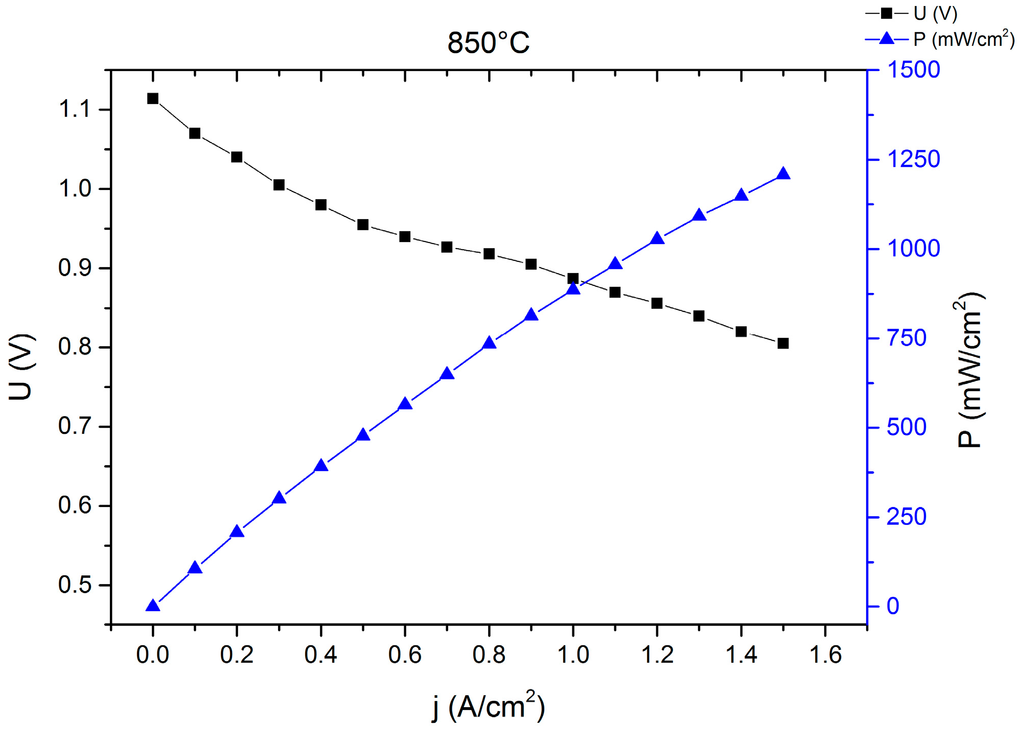
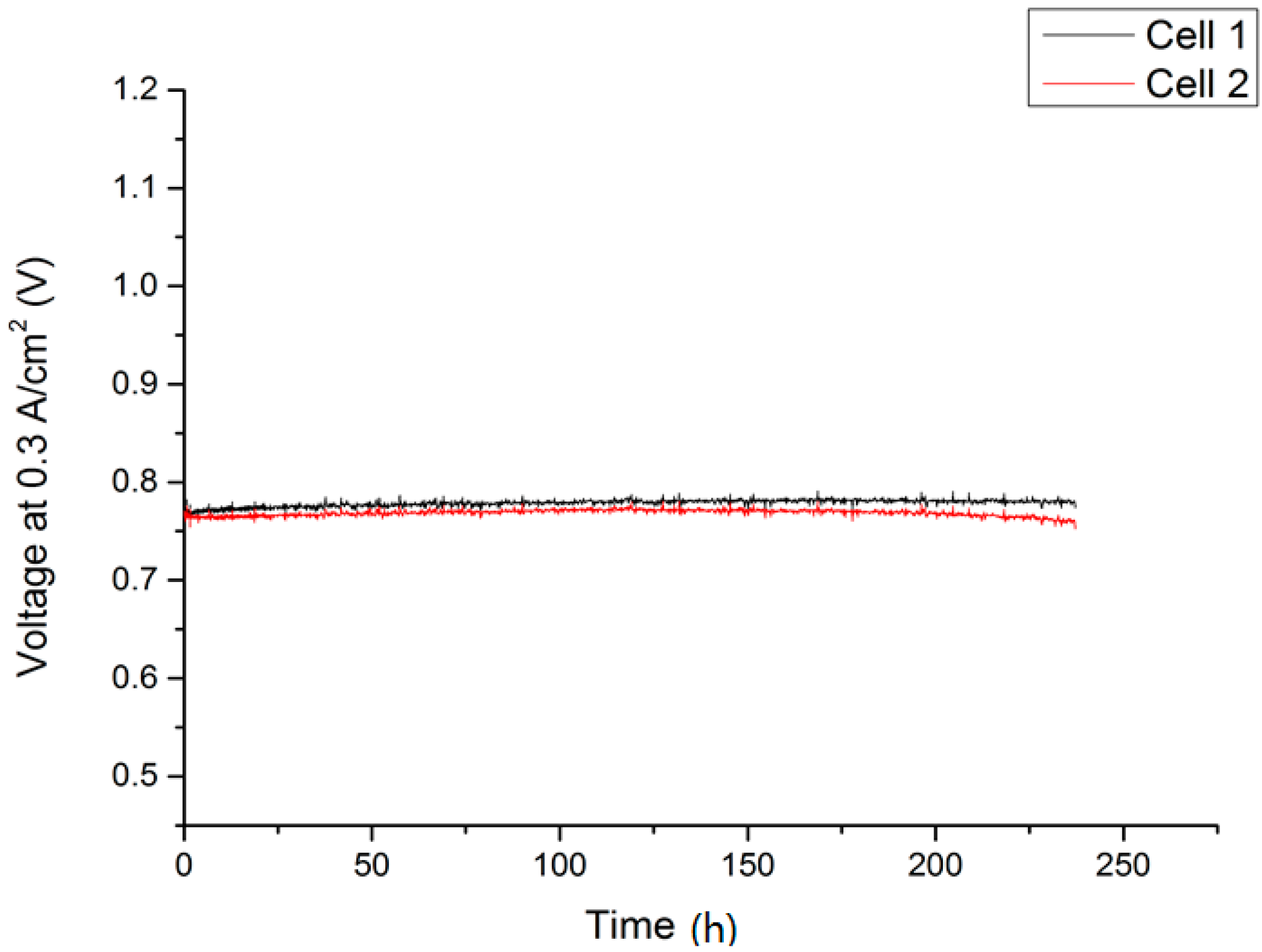
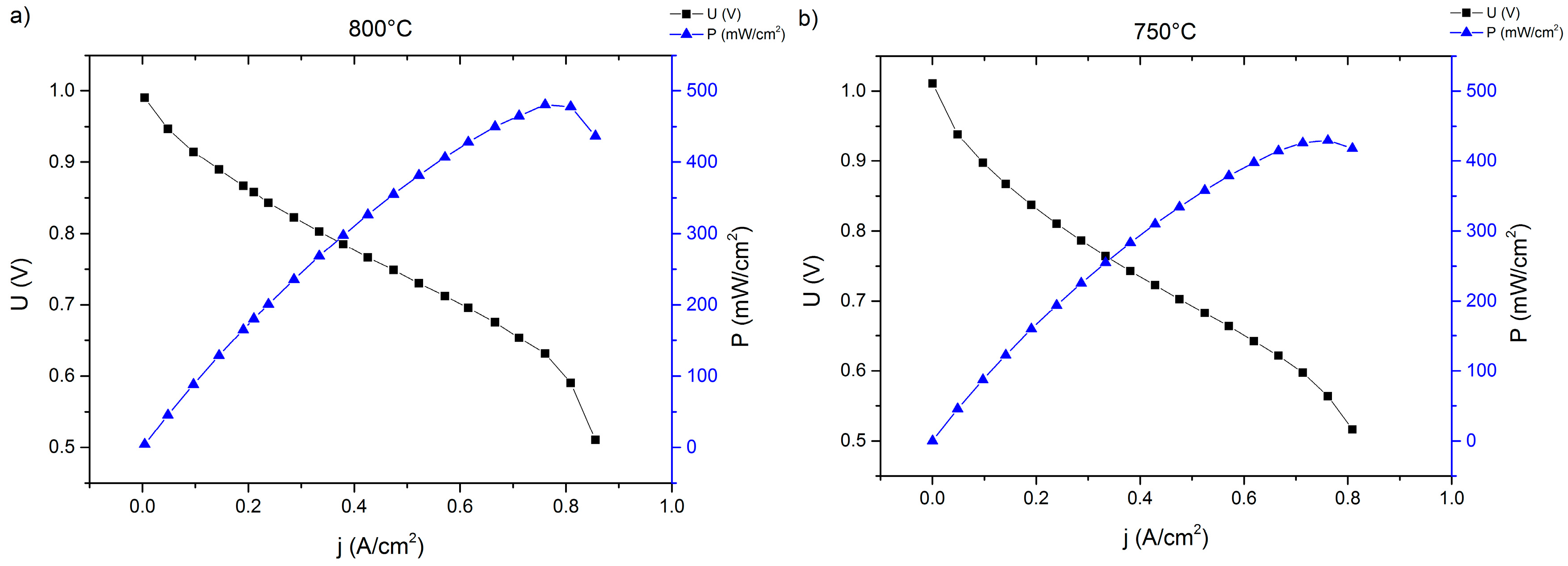
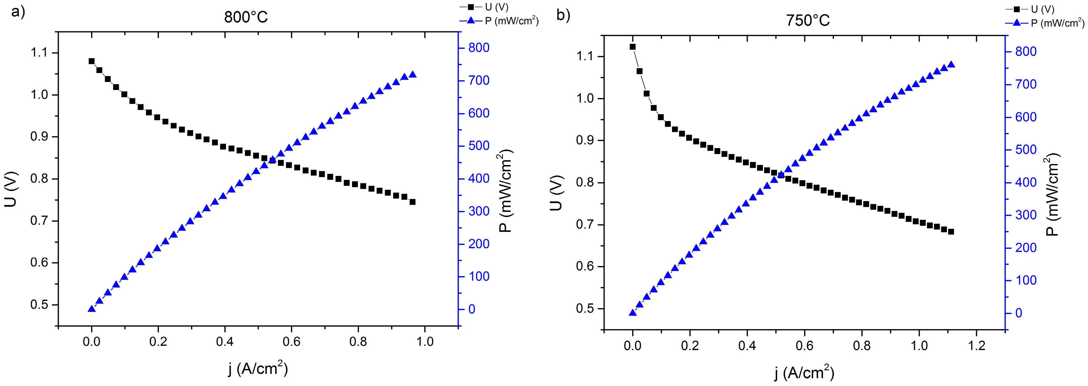
2.1. Single-Cell Test

Single-cell MSCs with small-area cathodes (1 cm2) have been characterized under various conditions [26]. An example is given in Figure 1. This cell was activated in-situ for 10 h at 850 °C in a dual gas atmosphere (air/3% humidified hydrogen) in order to achieve densification and adhesion of the green La0.58Sr0.4Co0.2Fe0.8O3-δ (LSCF) cathode to the barrier layer.
Although 10 h at 850 °C is not sufficient to ensure a sintering of the A-site-deficient LSCF cathode, the power densities obtained from single-cell tests with hydrogen are in a range that is comparable to full ceramic SOFCs (1.5 A/cm2 at 0.8 V and 850 °C). When the fuel gas is switched to a system-relevant simulated diesel reformate (50% N2, 15% H2 14% CO, 11% H2O, 10% CO2) and a temperature of 750 °C cell performances in the range of 200 to 630 mW/cm2 at 0.7 V were recorded [26], which is sufficient for the application of this type of cell in a mobile APU.

2.2. Lightweight Cassette Stack

A two-layer lightweight stack was set up with cells welded into the interconnector frame. After the glass sealant crystallized during the joining process for 100 h at 850 °C, gas tightness was achieved. The fuel gas was then set to humidified hydrogen and galvanostatic stack operation commencing at 750 °C, 0.3 A/cm2, and a fuel utilization of 20%. The resulting I–V and performance curves are shown in Figure 2 and Figure 3.
The measured IV-curves show a significantly reduced performance of the MSC (300 mA/cm2 at 0.8 V and 800 °C) as part of the stack compared to the single-cell measurements, both in terms of open circuit voltage (OCV) values and the slope of the voltage curve, which translates to a higher area-specific resistance. A lower OCV due to small internal leakages may be attributed to variations in the production cycle; the higher ASR compared to the single-cell test is a direct result of the introduction of several additional components which are necessary for stack operation, such as contacting oxide layers and or interconnector coatings. Due to the generally larger cell sizes, contact geometry and gas-flow are different compared to the single-cell laboratory experiment. Additionally, neighboring cells influence each other, for example with respect to temperature distribution [29]. These factors may contribute to the earlier onset of transport limitation at a current density of about 0.8 A/cm2, thus explaining the difference to the single cell measurement. However, these issues are common when comparing single-cell experiments with stack operation and a performance loss of 30%–50% is observed frequently [30].
In terms of performance degradation over time, the data indicate different behavior comparing cell 1 and cell 2 in Figure 2. While the cell voltage for cell 1 increases by 5.2 mV over 237 h of operation, which is probably a result of a slight improvement of the activity at the cathode side, cell 2 shows a progressive degradation of 18.62 mV or 2.4% over 237 h, which equates to 10.2% over 1000 h. This was, however, not related to intrinsic defects on the cell level, since OCV values for both cells were similar at 1.011 V (cell 1) and 1.015 V (cell 2) at 750 °C after the joining process, but rather were a direct result of an external leakage and subsequent reoxidation of cell 2 that developed during the course of the experiment, which resulted in an area increase in dark gray oxidized domains and some cracks in the cathode layer in the scanning electron microscopy (SEM) analysis. Cell 1, on the other hand, was subjected to less microstructural degradation, as can be seen in Figure 4a. A cross-section of cell 2 is presented in Figure 4b.
Although the electrical performance of cell 1 did not show progressive degradation, an incipient corrosion of the metal substrate is visible as dark gray areas in Figure 4a (left). At the present time, it is unclear what the effect will be on the long term stability of the cell and the study of these issues is now part of research at the recently established Christian-Doppler Laboratory [31].
The Ni/8YSZ, however, was not subjected to severe microstructural changes and the thin film electrolyte was found to be crack-free for the entire surveyed area. Additionally, the LSCF-cathode activated in situ shows good adherence to the electrolyte membrane and the porosity distribution was found to be homogeneous.

2.3. Stationary Stack

In order to exclude influences characteristic of the lightweight stack design, an additional two-layer stack was set up according to a well-known stationary stack design. For this test, a higher, more system-relevant current density of 0.5 A/cm2 was selected. Before galvanostatic operation, an in situ activation of the cathode was conducted at 850 °C in dual gas conditions (air-side electrode: atmospheric air, fuel-side electrode: argon stream) for 100 h. After activation, IV curves were recorded with humidified hydrogen as fuel gas at different temperatures (see Figure 5).
Both I-V curves show a significantly higher performance of the Plansee MSCs compared to the corresponding results from the lightweight stack (Figure 3). This is true for both cells from both stacks and can be explained by the improved electrical contact in the stationary design. Additionally, both cells in the stationary design show a higher OCV-value because of improved internal and external gas-tightness and a later onset of the gas-transport limitation, which is a result of a more efficient layout of the distribution manifolds and gas channels compared to the lightweight system.
The initial cell characteristics, as shown in Figure 5, were very promising. However, during the operation of the stack elevated degradation was recorded (see Figure 6). Over the course of galvanostatic operation (43 h), cell 1 lost 31 mV or 4.15% of the initial value, while cell 2 degraded by 61 mV (8.31%). Although the rate of performance loss in Figure 6 decreased considerably with increasing time at 0.5 A/cm2, we decided to cool down the stack and investigate the cells’ microstructure. Representative cross-sections are shown in Figure 7.
Although a slight internal leakage was detected after cooling down the stack, the thin 8YSZ electrolyte membrane was intact along the analyzed cross-sections (see Figure 7). No significant increase in local defect densities was observed compared to the initial state. Furthermore, the cathode microstructure and contact to the electrolyte were well established. EDS analysis of the cathode and electrolyte did not reveal any indications of a stoichiometric change in comparison to the as-prepared state.
However, signs of progressive corrosion of the porous metal-support were found. The ITM substrate exhibited a large number of dark gray areas (see Figure 7, left), which were identified as Cr/Fe oxide phases by EDS analysis. These oxide areas are also found in direct contact with the Gd2O3-doped CeO2 (GDC) diffusion barrier, indicating insufficient inhibition of the cation transport under these conditions (see Figure 8).
These interdiffusion phenomena may have been caused by insufficient stability of the barrier material GDC under the applied conditions. Indeed, it has been reported previously that doped cerates are prone to oxygen loss and phase transformation under highly reducing atmospheres, which enables interaction with neighboring materials or even decomposition [32].
Higher performance degradation rates, compared to full ceramic SOFCs, are a relatively common phenomenon for MSCs and have been reported for various cell concepts by other groups [13,21,33,34,35]. Reasons for this are in part the presence of the porous steel support, which may oxidize or coarsen during operation and can, at least in part, interact with the catalytically active centers of the anode (usually Ni). By applying a suitable and more redox-stable barrier layer, the expected lifetime of the MSC will increase significantly, while electrical properties remain largely unaffected.

3. Materials and Methods

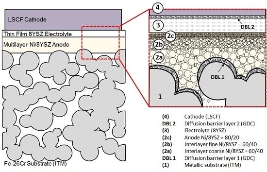
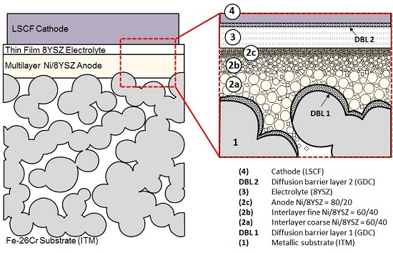
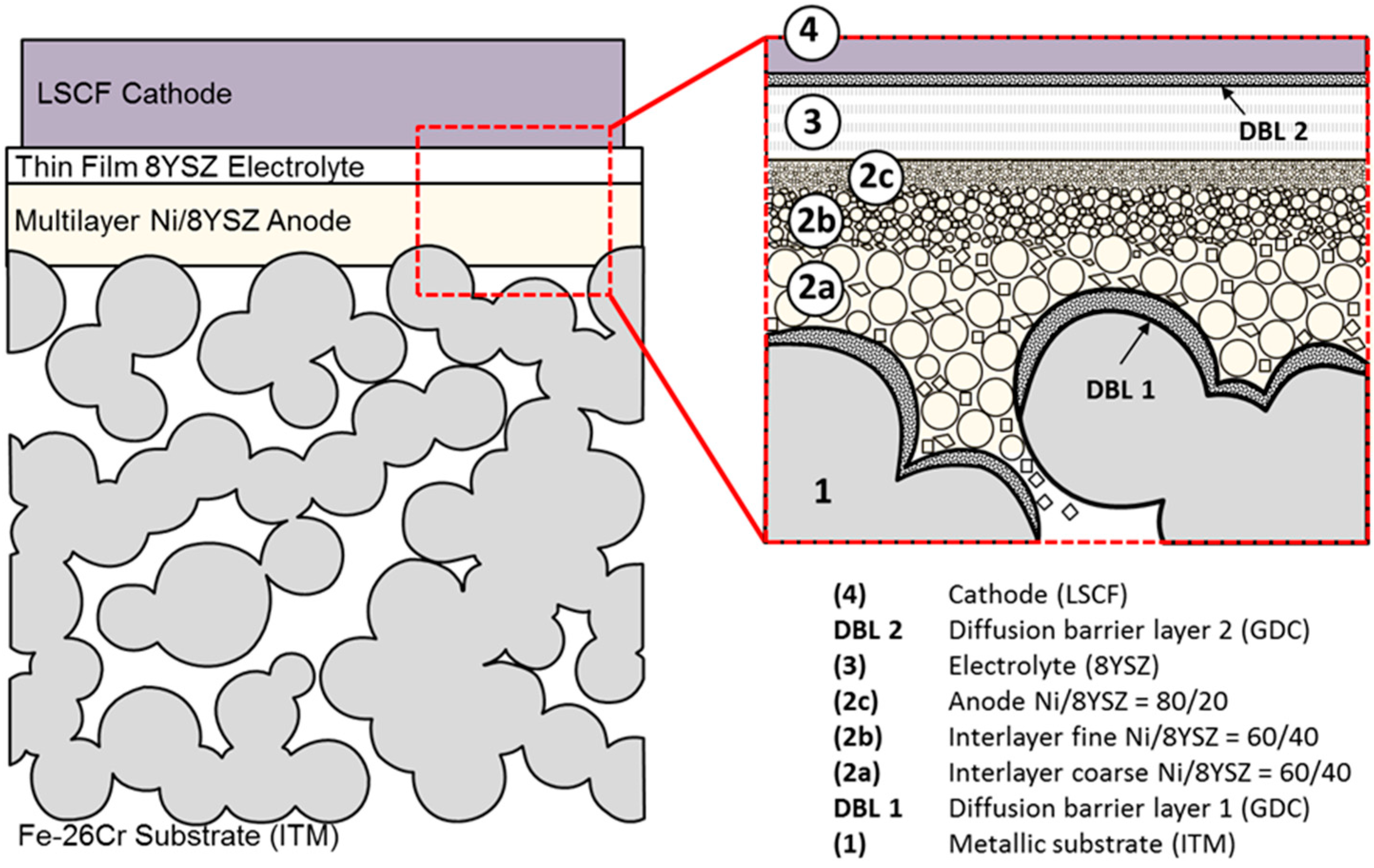
3.1. Cell Design and Manufacturing
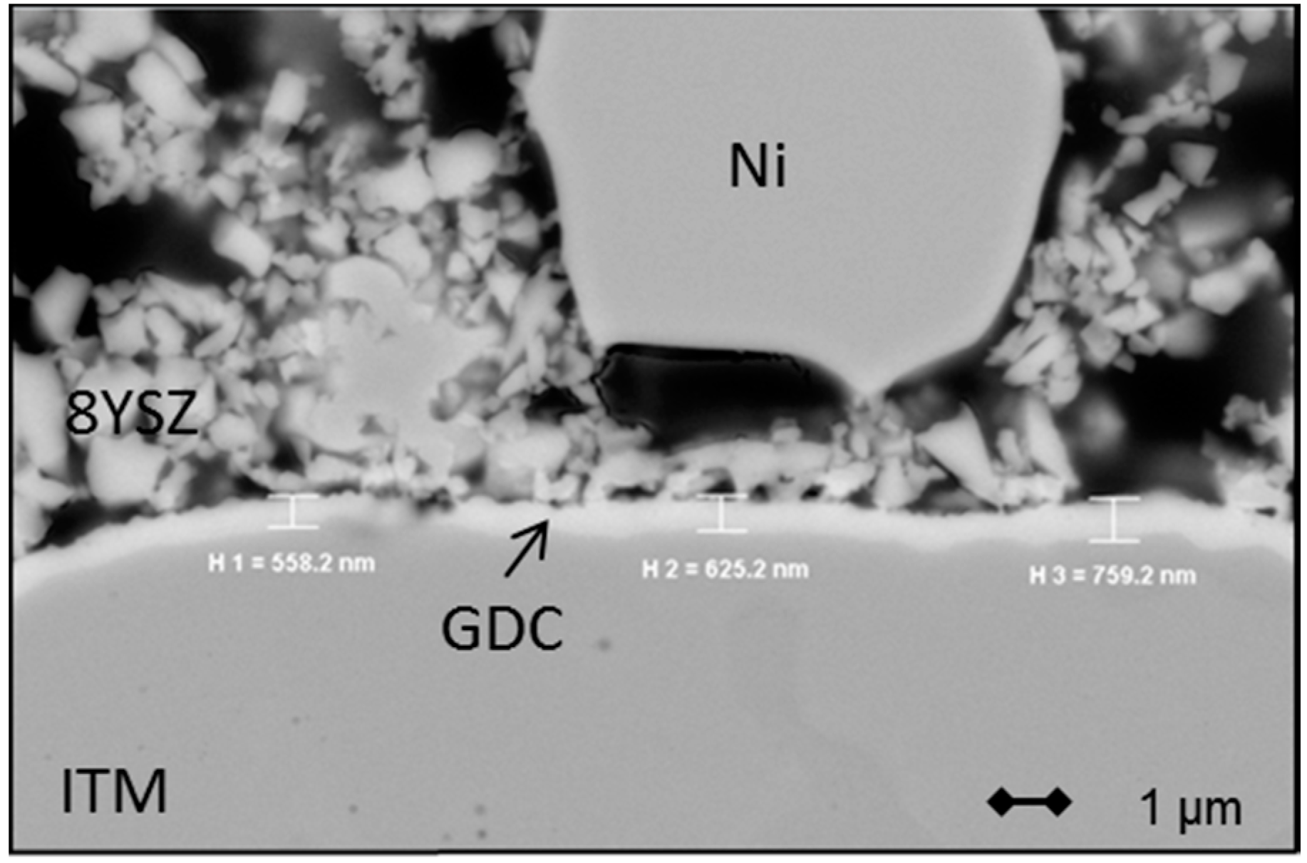
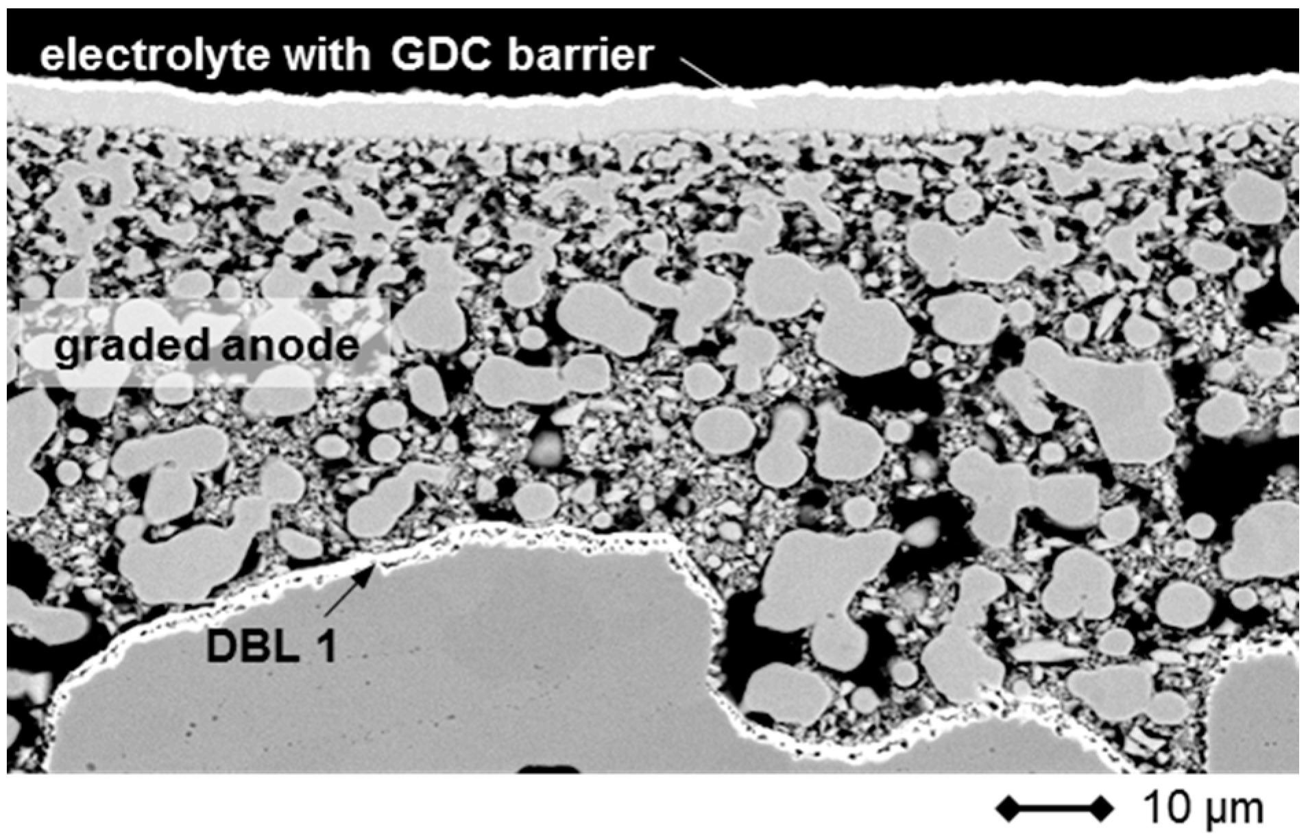
The cell design is presented schematically in Figure 9. The first step in the production cycle is the manufacturing of the 0.8 mm thick porous metal support (Cr26-Fe, ITM) by a powder-metallurgical process. To avoid interdiffusion of Fe and Cr into the anode, the substrate is coated with a 500 nm thin Gd2O3-doped CeO2 (GDC) layer by magnetron sputtering. In the second step, a 40 µm multilayer nickel/8%-Y2O3-doped ZrO2 (Ni/8YSZ) anode is applied to the substrate by screen-printing and subsequently annealed in hydrogen atmosphere. The composition of the anode paste is varied in each step (finer particles, lower porosity) to ensure a graded improvement of the surface, which is necessary for the application of the 4 µm electrolyte membrane in step 3 via gas-flow sputtering (GFS). Finally, a 40 µm LSCF cathode is screen printed on top of a magnetron-sputtered 500 nm thin GDC diffusion barrier. Each step will be discussed in detail below.

3.1.1. Substrate

The substrate (ITM) consists of an oxide dispersion-strengthened (OSD) ferritic steel containing 26% chromium, which is alloyed with small amounts of titanium, molybdenum, and Y2O3 additions. The material was prepared by a powder-metallurgical process and exhibits porosities of about 40%, good corrosion resistance and a thermal expansion coefficient that matches SOFC materials well and was found to be independent of the porosity [36,37,38]. ITM was formed into sheets of 0.8 mm in thickness and different areas from 25 cm2 to 100 cm2, which can be welded to the interconnector frame. Figure 10 shows a cross-section and a fracture image, in which the oxide crystals along the grain boundaries are visible.
The interdiffusion of cations from the metal substrate into the anode, and vice versa, can be a significant issue in the manufacturing and operation of MSCs and may lead to severe performance degradation [39]. Fe and Cr, once transported into the anode, form alloys with the Ni-catalyst and, thus, reduce cell performance. A number of possible protective coatings for different steel supports displaying sufficient chemical stability, a matching thermal expansion coefficient (TEC), and electrical conductivity have been explored in the literature and shown to be effective [39,40,41]. In this study we decided to produce a thin (0.5–1.0 µm) GDC layer by magnetron sputtering on top of the porous substrate, which is shown in Figure 11.

3.1.2. Fuel-Side Electrode

In order to achieve a graded transfer from the large particle and pore sizes of the ITM substrate, a 3-step screen-printing process was developed. In contrast to the manufacturing of full ceramic SOFCs, which relies on atmospheric sintering of NiO, the screen printing pastes for the Plansee MSC are based on metallic Ni particles. To avoid high-temperature corrosion of the metal substrate, sintering has to be conducted in reducing atmosphere and anode porosities have to be defined by the organic content of the paste. Sintering is conducted at 1180 °C in hydrogen atmosphere.
By gradually reducing the particle size of Ni in the screen-printing pastes and adjusting the solid load, composition and paste rheology a very smooth and homogeneous surface was achieved, which is necessary for the successful application of a thin 8YSZ electrolyte by gas-flow sputtering. A cross-section image of a sintered 3-layer anode is presented in Figure 12.

3.1.3. Electrolyte Membrane

Dense and thin (4 µm) 8YSZ electrolytes have been prepared on top of the graded Ni/8YSZ anode by means of a gas-flow sputter process for active areas of up to 84 cm2. This method allows high deposition rates and a wide range of possible compounds and is generally considered to be a more economic physical vapor deposition (PVD) method [42].
After GFS processing, the 8YSZ membrane shows a low defect density and leakage rates of less than 3 × 10⁻⁴ hPa·dm3·s−1·cm−2 (Δp: 100 hPa) in air at room temperature have been obtained, which is sufficient for the electrical operation of the cell [27]. The 8YSZ layer adheres well to the anode surface and is able to withstand small height variations of the support even after operation (see Figure 13). Additionally, it was found that the thin membrane is flexible with respect to mechanical stresses which may arise from the oxidation of the anode or variations in thermal expansion coefficients [43]. This is a phenomenon which is characteristic of thin membranes, in general, and was recently reported for full ceramic SOFCs [44]. Due to the reactivity of the LSCF cathode material with zirconia, a dense 500 nm GDC layer is deposited by magnetron sputtering on top of the electrolyte in a second step to avoid the formation of strontium zirconates, which are detrimental to cell performance [45].

3.1.4. Air-Side Electrode

Cathodes 40 µm in thickness were applied by screen printing on top of the electrolyte/diffusion barrier layer. Sr- and Fe-doped lanthanum cobaltites, in general, and A-site-deficient LSCF, in particular, have been used for SOFCs of all kinds and lead to excellent cell performance [46,47]. However, due to the presence of the metal substrate, a conventional sintering route at temperatures higher than 1000 °C in air is not possible for the MSC. Due to this, the cathode was kept in its green state during stack assembly and the first heat-up of the cell. An in situ activation step (850 °C, 10 to 100 h) in dual gas conditions was applied in order to ensure sufficient adherence to the electrolyte and, thus, good cell performance. The microstructure of the cathode after this activation step is shown in Figure 13 in Section 3.1.3.

3.1.5. Stack Assembly

Two MSCs with an active area of 84 cm2 each were assembled into a lightweight cassette design that was developed for a mobile APU. The setup has been published earlier [26] and will only be discussed briefly. The interconnector frame was made up of dense ITM and accommodates the gas distribution manifolds. High temperature sealing was accomplished by using a conventional glass-ceramic [48]. During the joining process, the two-layer short stack was heated to 850 °C for 100 h in a dual gas atmosphere under a mechanical load of 0.5 kN. After that, the temperature was set to 750 °C and stack operation commenced under constant current conditions (0.3 A/cm2).
In addition to the lightweight setup, 10 × 10 cm2 MSCs were incorporated into a stack that was developed for stationary applications. Details can be found in a previous publication [29]. The joining process was identical to the lightweight-stack. Electrical operation was conducted galvanostatically at a lower temperature (700 °C) and under higher current density (0.5 A/cm2), compared to the lightweight setup, in order to expose the MSCs to conditions that were more relevant to the system’s point of operation.
For both stacks, humidified hydrogen was supplied to the fuel-side electrode (cassette stack Uf = 20%, stationary-stack Uf = 40%).

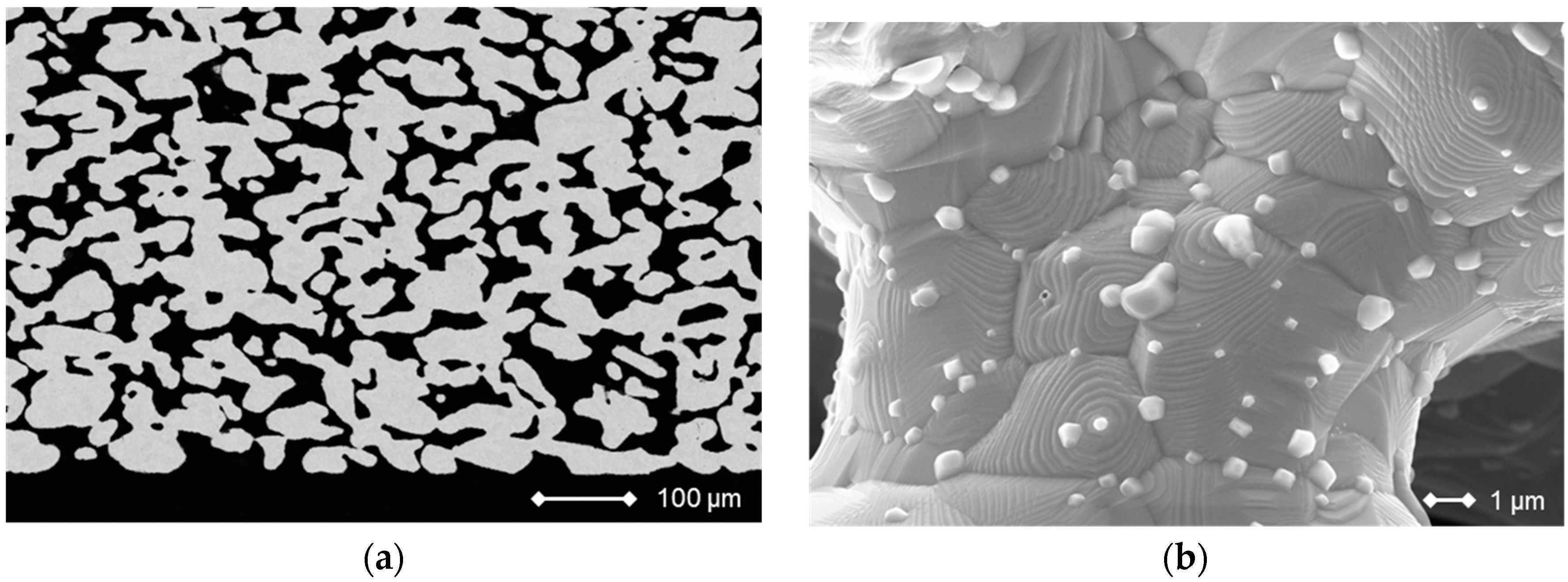
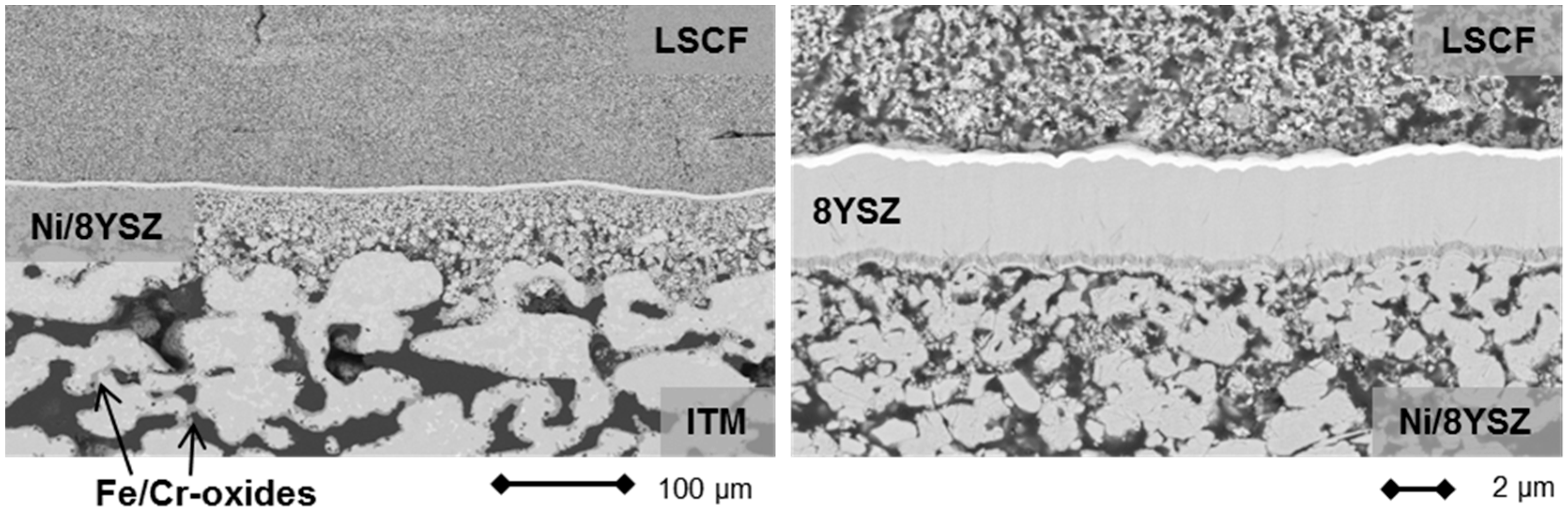
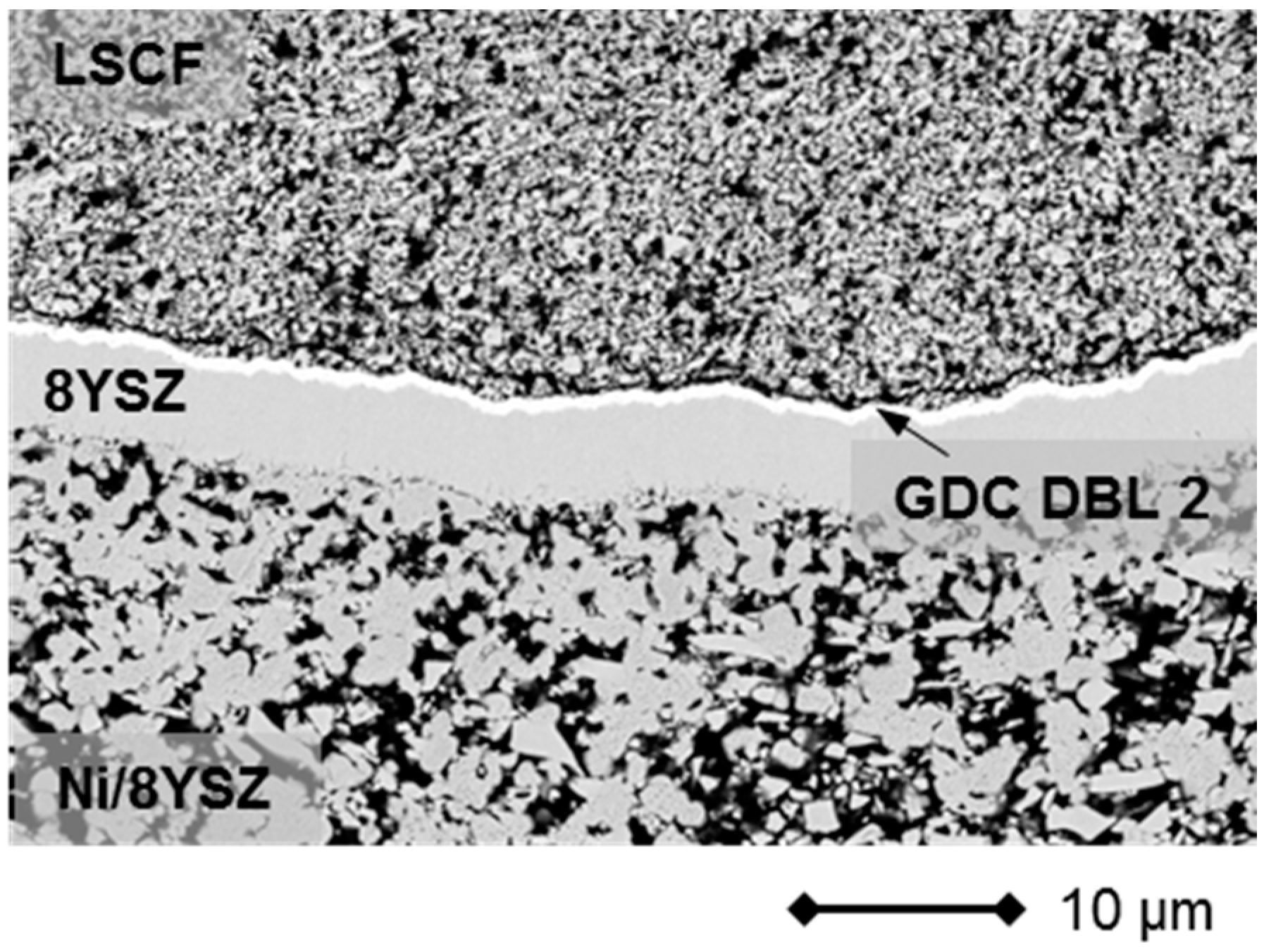
3.1.6. Electron Microscopy

The SEM (scanning electron microscopy) images of polished cross sections were taken using a Zeiss Ultra55 (Oberkochen, Germany) with INCA Energy 355 EDX (energy-dispersive X-ray) and INCA Crystal EBSD (electron backscatter diffraction) detectors.

4. Conclusions

A metal-supported SOFC based on a porous steel substrate, a graded three-layer Ni/8YSZ anode, and a thin film 8YSZ membrane was operated in two different stack designs. The cells were characterized in terms of electrical performance and microstructural behavior. Single cell IV-characterization of such cells with an LSCF cathode activated in situ displays power densities of about 1 W/cm2 at 800 °C and 1.5 A/cm2. A two-layer lightweight MSC stack with an 84 cm2 active cell area was operated at 0.3 A/cm2 for more than 237 h at 750 °C. IV characterization of the cells activated in situ showed a reduction of the power densities obtained due to contacting and gas-transport losses, which is in line with other studies. A further two layer MSC stack in a stationary design was set up and operated at 0.5 A/cm2 for 43 h. For both stacks, one cell each showed increased degradation rates, while the other one remained relatively stable. The increased degradation rate is at least in part the result of setup related issues, which was confirmed by post-test microstructural analysis of the cells. Even though cell degradation for this MSC concept was higher compared to traditional full ceramic SOFCs, the first results from stack operation show performance data that are sufficient for the operation of a mobile APU, while a future redesign of current diffusion barrier layers will contribute greatly to extending cell lifetime.

Acknowledgments

The authors would like to thank the German Federal Ministry for Economic Affairs and Energy (BMWi) for financial support as part of the MetAPU and NextGen MSC projects (contract No. 0327779F and 0327867A); We would also like to thank Marco Brandner and Wolfgang Schafbauer, Innovation Services, Plansee SE, Reutte Austria, for providing the MSCs, as well as for financial and technical support; Parts of the work were performed in cooperation with the Christian Doppler Laboratory for Interfaces in Electrochemical Energy Converters. Equal shares in the funding of Christian Doppler Laboratories are borne by public authorities and the companies directly involved in the laboratories. The most important source of funding from public authorities is the Austrian Bundesministerium für Wissenschaft, Forschung und Wirtschaft (BMWFW). This funding is gratefully acknowledged; Furthermore, the authors would like to thank Peter Batfalsky and Arnold Cramer, Zentralinstitut für Engineering, Elektronik und Analytik (ZEA-1), Forschungszentrum Jülich GmbH, Germany for assembly and post-test analysis of the MSC-stacks, as well as André Weber, Institut für Angewandte Materialien–Werkstoffe der Elektrotechnik (IAM–WET), Karlsruher Institut für Technologie (KIT), Karlsruhe, Germany for IV-characterization of MSC-single cells.

Author Contributions

Daniel Roehrens supported the stack-tests, SEM analysis and wrote the paper, Ute Packbier, Qingping Fang and Ludger Blum carried out and supervised the electrical testing, Doris Sebold carried out the SEM analysis, Martin Bram prepared visualizations and Norbert Menzler supervised the study.

Conflicts of Interest

The authors declare no conflict of interest.

References

  1. Steele, B.C.H.; Heinzel, A. Materials for fuel-cell technologies. Nature 2001, 414, 345–352. [Google Scholar] [CrossRef] [PubMed]
  2. Singhal, S.C. Solid oxide fuel cells for stationary, mobile, and military applications. Solid State Ion. 2002, 152, 405–410. [Google Scholar] [CrossRef]
  3. Stambouli, A.B.; Traversa, E. Solid oxide fuel cells (SOFCS): A review of an environmentally clean and efficient source of energy. Renew. Sustain. Energy Rev. 2002, 6, 433–455. [Google Scholar] [CrossRef]
  4. Goodenough, J.B. Oxide-ion electrolytes. Annu. Rev. Mater. Res. 2003, 33, 91–128. [Google Scholar] [CrossRef]
  5. Brett, D.J.L.; Atkinson, A.; Brandon, N.P.; Skinner, S.J. Intermediate temperature solid oxide fuel cells. Chem. Soc. Rev. 2008, 37, 1568–1578. [Google Scholar] [CrossRef] [PubMed]
  6. Sun, C.; Hui, R.; Roller, J. Cathode materials for solid oxide fuel cells: A review. J. Solid State Electrochem. 2010, 14, 1125–1144. [Google Scholar] [CrossRef]
  7. Fergus, J.W. Metallic interconnects for solid oxide fuel cells. Mater. Sci. Eng. A 2005, 397, 271–283. [Google Scholar] [CrossRef]
  8. Quadakkers, W.J. Metallic materials in solid oxide fuel cells. Mater. Res. 2004, 7, 203–208. [Google Scholar] [CrossRef]
  9. Menzler, N.; Tietz, F.; Uhlenbruck, S.; Buchkremer, H.; Stöver, D. Materials and manufacturing technologies for solid oxide fuel cells. J. Mater. Sci. 2010, 45, 3109–3135. [Google Scholar] [CrossRef]
  10. Tietz, F.; Mai, A.; Stöver, D. From powder properties to fuel cell performance—A holistic approach for SOFC cathode development. Solid State Ion. 2008, 179, 1509–1515. [Google Scholar] [CrossRef]
  11. Singhal, S.C. Advances in solid oxide fuel cell technology. Solid State Ion. 2000, 135, 305–313. [Google Scholar] [CrossRef]
  12. Steele, B.C.H. Materials for IT-SOFC stacks: 35 years R&D: The inevitability of gradualness? Solid State Ion. 2000, 134, 3–20. [Google Scholar]
  13. Tucker, M.C. Progress in metal-supported solid oxide fuel cells: A review. J. Power Sources 2010, 195, 4570–4582. [Google Scholar] [CrossRef]
  14. Tucker, M.C.; Lau, G.Y.; Jacobson, C.P.; DeJonghe, L.C.; Visco, S.J. Stability and robustness of metal-supported SOFCs. J. Power Sources 2008, 175, 447–451. [Google Scholar] [CrossRef]
  15. Ansar, A.; Szabo, P.; Arnold, J.; Ilhan, Z.; Soysal, D.; Costa, R.; Zagst, A.; Gindrat, M.; Franco, T. Metal supported solid oxide fuel cells and stacks for auxilary power units—Progress, challenges and lessons learned. ECS Trans. 2011, 35, 147–155. [Google Scholar]
  16. Villarreal, I.; Jacobson, C.; Leming, A.; Matus, Y.; Visco, S.; De Jonghe, L. Metal-supported solid oxide fuel cells. Electrochem. Solid State Lett. 2003, 6, A178–A179. [Google Scholar] [CrossRef]
  17. Brandon, N.P.; Corcoran, D.; Cummins, D.; Duckett, A.; El-Khoury, K.; Haigh, D.; Leah, R.; Lewis, G.; Maynard, N.; McColm, T.; et al. Development of metal supported solid oxide fuel cells for operation at 500–600 °C. J. Mater. Eng. Perform. 2004, 13, 253–256. [Google Scholar] [CrossRef]
  18. Tucker, M.C.; Lau, G.Y.; Jacobson, C.P.; DeJonghe, L.C.; Visco, S.J. Performance of metal-supported SOFCs with infiltrated electrodes. J. Power Sources 2007, 171, 477–482. [Google Scholar] [CrossRef]
  19. Blennow, P.; Hjelm, J.; Klemensø, T.; Persson, A.; Brodersen, K.; Srivastava, A.; Frandsen, H.; Lundberg, M.; Ramousse, S.; Mogensen, M. Development of planar metal supported SOFC with novel cermet anode. ECS Trans. 2009, 25, 701–710. [Google Scholar]
  20. Huang, Q.-A.; Wang, B.; Qu, W.; Hui, R. Impedance diagnosis of metal-supported SOFCs with SDC as electrolyte. J. Power Sources 2009, 191, 297–303. [Google Scholar] [CrossRef]
  21. Rodriguez-Martinez, L.M.; Otaegi, L.; Alvarez, M.; Rivas, M.; Gomez, N.; Zabala, A.; Arizmendiarrieta, N.; Antepara, I.; Urriolabeitia, A.; Olave, M.; et al. Degradation studies on tubular metal supported SOFC. ECS Trans. 2009, 25, 745–752. [Google Scholar]
  22. Blennow, P.; Hjelm, J.; Klemensø, T.; Ramousse, S.; Kromp, A.; Leonide, A.; Weber, A. Manufacturing and characterization of metal-supported solid oxide fuel cells. J. Power Sources 2011, 196, 7117–7125. [Google Scholar] [CrossRef] [Green Version]
  23. Matus, Y.B.; De Jonghe, L.C.; Jacobson, C.P.; Visco, S.J. Metal-supported solid oxide fuel cell membranes for rapid thermal cycling. Solid State Ion. 2005, 176, 443–449. [Google Scholar] [CrossRef]
  24. Lang, M.; Szabo, P.; Ilhan, Z.; Cinque, S.; Franco, T.; Schiller, G. Development of solid oxide fuel cells and short stacks for mobile application. J. Fuel Cell Sci. Technol. 2007, 4, 384–391. [Google Scholar] [CrossRef]
  25. Franco, T.; Brandner, M.; Rüttinger, M.; Kunschert, G.; Venskutonis, A.; Sigl, L. Recent development aspects of metal supported thin-film SOFC. ECS Trans. 2009, 25, 681–688. [Google Scholar]
  26. Franco, T.; Haydn, M.; Weber, A.; Schafbauer, W.; Blum, L.; Packbier, U.; Roehrens, D.; Menzler, N.H.; Rechberger, J.; Venskutonis, A.; et al. The status of metal-supported SOFC development and industrialization at plansee. ECS Trans. 2013, 57, 471–480. [Google Scholar] [CrossRef]
  27. Haydn, M.; Ortner, K.; Franco, T.; Uhlenbruck, S.; Menzler, N.H.; Stöver, D.; Bräuer, G.; Venskutonis, A.; Sigl, L.S.; Buchkremer, H.-P.; et al. Multi-layer thin-film electrolytes for metal supported solid oxide fuel cells. J. Power Sources 2014, 256, 52–60. [Google Scholar] [CrossRef]
  28. Rüttinger, M.; Mücke, R.; Franco, T.; Büchler, O.; Menzler, N.H.; Venskutonis, A. Metal-supported cells with comparable performance to anode-supported cells in short-term stack environment. ECS Trans. 2011, 35, 259–268. [Google Scholar]
  29. Celik, I.B.; Pakalapati, S.R. From a Single cell to a stack modeling. In Modeling Solid Oxide Fuel Cells: Methods, Procedures and Techniques; Bove, R., Ubertini, S., Eds.; Springer Netherlands: Dordrecht, The Netherlands, 2008; pp. 123–182. [Google Scholar]
  30. Blum, L.; Buchkremer, H.P.; Gross, S.; Gubner, A.; de Haart, L.G.J.; Nabielek, H.; Quadakkers, W.J.; Reisgen, U.; Smith, M.J.; Steinberger-Wilckens, R.; et al. Solid oxide fuel cell development at forschungszentrum juelich. Fuel Cells 2007, 7, 204–210. [Google Scholar] [CrossRef]
  31. Rojek, V.; Roehrens, D.; Brandner, M.; Menzler, N.H.; Guillon, O.; Opitz, A.K.; Bram, M. Development of high performance anodes for metal-supported fuel cells. ECS Trans. 2015, 68, 1297–1307. [Google Scholar] [CrossRef]
  32. Kim, K.J.; Choi, G.M. Phase stability and oxygen non-stoichiometry of Gd-doped ceria during sintering in reducing atmosphere. J. Electroceramics 2015, 35, 1–7. [Google Scholar] [CrossRef]
  33. Jeong, J.; Baek, S.-W.; Bae, J. A diesel-driven, metal-based solid oxide fuel cell. J. Power Sources 2014, 250, 98–104. [Google Scholar] [CrossRef]
  34. Blennow, P.; Sudireddy, B.R.; Persson, Å.H.; Klemensø, T.; Nielsen, J.; Thydén, K. Infiltrated SrTiO3: Fecr-based anodes for metal-supported SOFC. Fuel Cells 2013, 13, 494–505. [Google Scholar] [CrossRef]
  35. Choi, J.H.; Lee, T.; Choi, M.; Yoo, Y.-S.; Baek, S.-W.; Bae, J. Long-term performance of anode-supported SOFC integrated with metal interconnect by joining process. Int. J. Hydrogen Energy 2010, 35, 4285–4291. [Google Scholar] [CrossRef]
  36. Venskutonis, A.; Kunschert, G.; Mueller, E.; Hoehle, H.-M. P/M processing and coating technologies for fabrication of interconnect for stationary and mobile SOFC applications. ECS Trans. 2007, 7, 2109–2115. [Google Scholar]
  37. Vasechko, V.; Pećanac, G.; Kuhn, B.; Malzbender, J. Mechanical properties of porous ITM alloy. Int. J. Hydrogen Energy 2016, 41, 562–569. [Google Scholar] [CrossRef]
  38. Megel, S.; Girdauskaite, E.; Sauchuk, V.; Kusnezoff, M.; Michaelis, A. Area specific resistance of oxide scales grown on ferritic alloys for solid oxide fuel cell interconnects. J. Power Sources 2011, 196, 7136–7143. [Google Scholar] [CrossRef]
  39. Kim, K.J.; Kim, S.J.; Choi, G.M. Y0.08Sr0.88TiO3–CeO2 composite as a diffusion barrier layer for stainless-steel supported solid oxide fuel cell. J. Power Sources 2016, 307, 385–390. [Google Scholar] [CrossRef]
  40. Brandner, M.; Bram, M.; Froitzheim, J.; Buchkremer, H.P.; Stöver, D. Electrically conductive diffusion barrier layers for metal-supported SOFC. Solid State Ion. 2008, 179, 1501–1504. [Google Scholar] [CrossRef]
  41. Yan, Y.; Bateni, R.; Harris, J.; Kesler, O. Fabrication of reactive element oxide coatings on porous ferritic stainless steel for use in metal-supported solid oxide fuel cells. Surf. Coat. Technol. 2015, 272, 415–427. [Google Scholar] [CrossRef]
  42. Jung, T.; Kälber, T.; Heide, V.v.d. Gas flow sputtering of oxide coatings: Practical aspects of the process. Surf. Coat. Technol. 1996, 86, 218–224. [Google Scholar] [CrossRef]
  43. Roehrens, D.; Han, F.; Haydn, M.; Schafbauer, W.; Sebold, D.; Menzler, N.H.; Buchkremer, H.P. Advances beyond traditional SOFC cell designs. Int. J. Hydrogen Energy 2015, 40, 11538–11542. [Google Scholar] [CrossRef]
  44. Keuter, T.; Roehrens, D.; Menzler, N.H.; Vaßen, R. Redox-stable high-performance thin-film solid oxide fuel cell. ECS Trans. 2015, 68, 2001–2009. [Google Scholar] [CrossRef]
  45. Mai, A.; Haanappel, V.A.C.; Uhlenbruck, S.; Tietz, F.; Stöver, D. Ferrite-based perovskites as cathode materials for anode-supported solid oxide fuel cells: Part I. Variation of composition. Solid State Ion. 2005, 176, 1341–1350. [Google Scholar] [CrossRef]
  46. Mai, A.; Haanappel, V.A.C.; Tietz, F.; Stöver, D. Ferrite-based perovskites as cathode materials for anode-supported solid oxide fuel cells: Part II. Influence of the CGO interlayer. Solid State Ion. 2006, 177, 2103–2107. [Google Scholar] [CrossRef]
  47. Tai, L.W.; Nasrallah, M.M.; Anderson, H.U.; Sparlin, D.M.; Sehlin, S.R. Structure and electrical properties of La1−xSrxCo1−yFeyO3. Part 1. The system La0.8Sr0.2Co1−yFeyO3. Solid State Ion. 1995, 76, 259–271. [Google Scholar] [CrossRef]
  48. Gross, S.M.; Koppitz, T.; Remmel, J.; Reisgen, U. Glass-Ceramic Materials of the System BaO-CaO-SiO2 as Sealants for Sofc Applications. In Advances in Solid Oxide Fuel Cells: Ceramic Engineering and Science Proceedings; John Wiley & Sons, Inc.: Hoboken, NJ, USA, 2008; pp. 239–245. [Google Scholar]
Figure 1. I–V curve of a planar 5 cm by 5 cm2 single cell MSC with a 4 µm thin layer 8YSZ electrolyte, a Ni/8YSZ anode and an LSCF cathode at 850 °C in 3% humidified hydrogen after 10 h of in-situ activation. For more details about the manufacturing refer to Section 3.
Materials 09 00762 g001
Figure 2. Performance of two metal-supported cells operated in a lightweight stack at 750 °C under galvanostatic conditions.
Materials 09 00762 g002
Figure 3. I-V- and I-P-curves of cell 1 of the lightweight MSC stack after joining, measured at 800 °C (a) and 750 °C (b).
Materials 09 00762 g003
Figure 4. (a) SEM images of cross sections of cell 1 after operation at 750 °C under load (0.3 A/cm2). The dark gray areas within the metal substrate ITM (intermediate temperature metal, Plansee SE, Reutte, Austria) are comprised of chromium and iron oxides; and (b) SEM images of cross-sections of cell 2 after operation at 750 °C under load (0.3 A/cm2). The dark gray areas within the metal substrate ITM are comprised of chromium and iron oxides.
Materials 09 00762 g004
Figure 5. I-V- and I-P-curves of cell 1 during operation in a stationary stack after joining at 800 °C (a) and 750 °C (b).
Materials 09 00762 g005
Figure 6. Performance of two MSC cells operated in a stationary stack at 750 °C under galvanostatic conditions (0.5 A/cm2).
Materials 09 00762 g006
Figure 7. Cross-section of MSC 2 (see Figure 6) after operation in a stationary design.
Materials 09 00762 g007
Figure 8. Cross-section of MSC 2 after operation in a stationary design exhibiting interdiffusion phenomena at contact interface between substrate/DBL/anode.
Materials 09 00762 g008
Figure 9. Schematic representation of the Plansee SE MSC. Ratios given for the composition of the anode in (2) are in weight percent.
Materials 09 00762 g009
Figure 10. Cross section of the Cr26-Fe substrate material ITM (a) and fracture image (b). The bright crystals along the grain boundaries were identified as yttria and titania.
Materials 09 00762 g010
Figure 11. SEM image of a cross-section of an MSC with a magnetron sputtered GDC diffusion barrier layer covering the metal substrate.
Materials 09 00762 g011
Figure 12. SEM-image of a cross section through the graded anode of an MSC before application of the cathode.
Materials 09 00762 g012
Figure 13. SEM image of a cross-section through an MSC highlighting the GFS applied 8YSZ electrolyte and the GDC diffusion barrier after operation. The cell was activated in situ for 100 h in a dual gas atmosphere at 850 °C and operated for 100 h at 750 °C.
Materials 09 00762 g013

