
A Comparative Study on Permanent Mold Cast and Powder Thixoforming 6061 Aluminum Alloy and Sicp/6061Al Composite: Microstructures and Mechanical Properties

Abstract
:1. Introduction
2. Materials and Methods
2.1. Fabrication PMC of 6061 Alloy
2.2. Fabrication PTF of Sicp/6061 Composite and 6061 Alloy
2.3. Material Characterization
2.4 Tensile Testing
3. Results and Discussion
3.1. Microstructural Analysis
- the initial coarsening
- structure separation and spheroidization
- final coarsening
3.2. Porosity Evaluation
3.3. Tensile Properties
3.4. Strengthening Mechanisms of Sicp
4. Conclusions
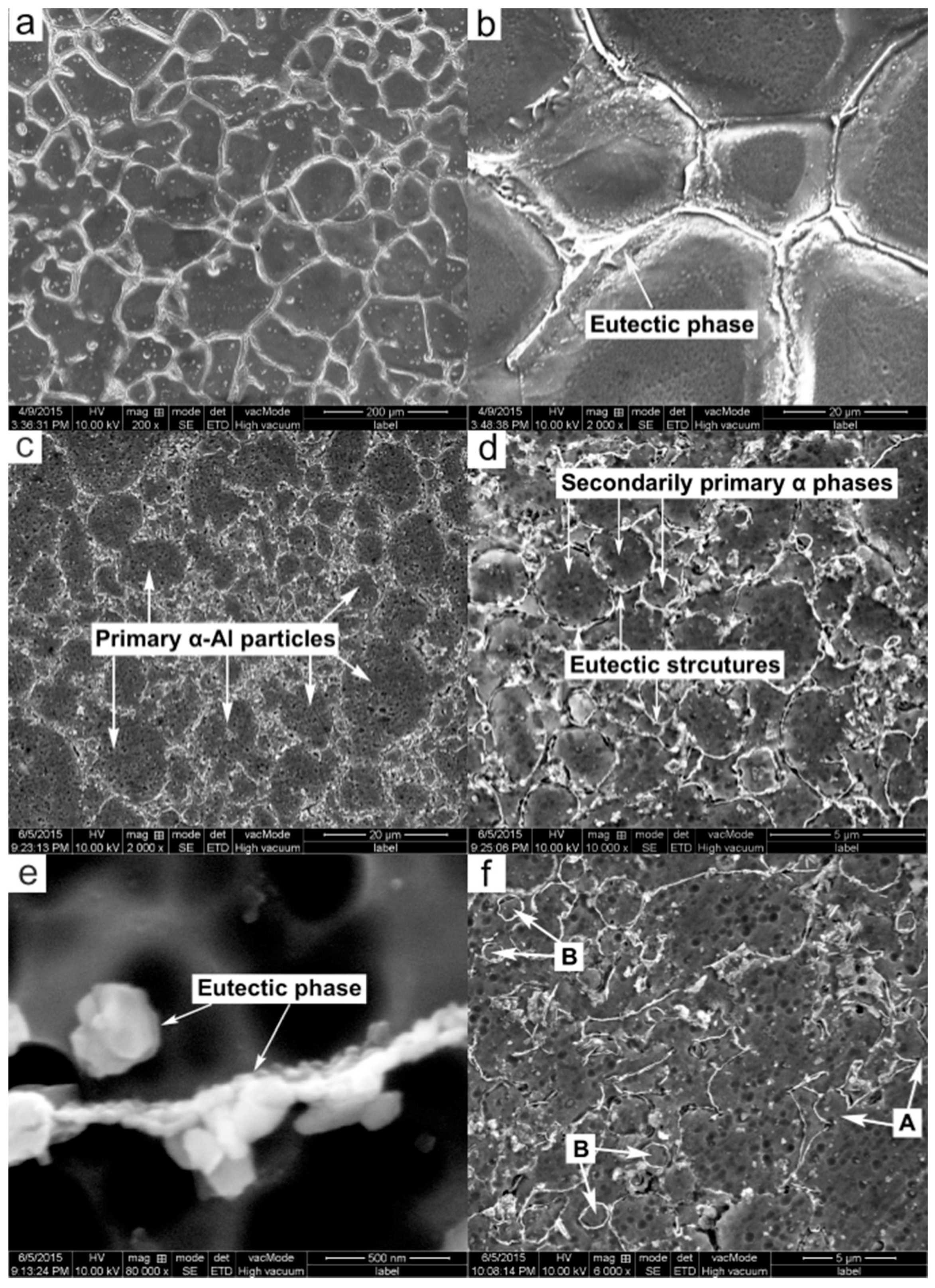
- The microstructure of the PMC-6061 alloy is composed of coarse and equiaxed α dendrites with an average size of 90.01 μm and interdendritic net-like eutectic phases, but the microstructure of the PTF-SiCp/6061Al composite, similar to that of the PTF-6061 alloy, consists of near-spheroidal primary particles and intergranular secondarily solidified structures except SiCp, which are distributed in the secondarily solidified structures.
- The primary particles of the PTF composite are more irregular and the amount of secondarily solidified structures is lower than those of the PTF alloy because of the delayed microstructural evolution rate during partial remelting. Besides, the size of the primary particles is slightly smaller than that in the PTF alloy due to the delayed microstructural evolution rate as well as the pinning effect of SiCp against the coalescence of the nearby primary particles.
- The amount of Mg2Si based eutectic phases in the PTF materials is distinctly lower than that in the PMC alloy due to the dissolution of eutectic phases towards the primary α-Al particles during partial remelting. The eutectics amount in PTF composite is slightly lower than that in the PTF alloy owing to the reactions of Mg and Al with SiO2 on the surfaces of oxidized SiCp as well as the delayed microstructural evolution.
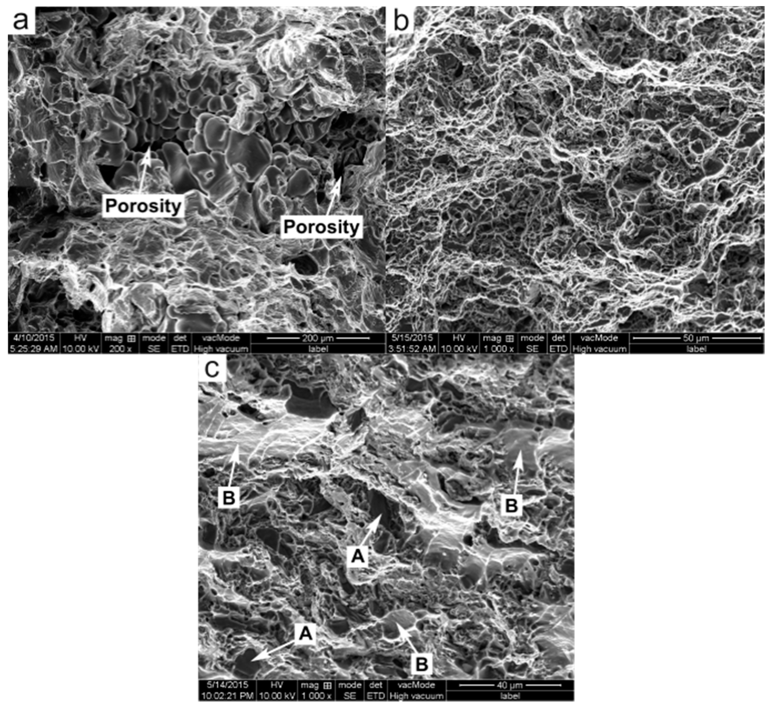
- The microstructures of the PTF materials are quite compact while that of the PMC alloy is porous. The porosity elimination in the PTF materials is due to the applied high pressure during solidification, the low filling velocity during mold filling, the improved feeding ability of near-spheroidal primary α-Al particles and the low liquid fraction of the semisolid slurry.
- The ultimate tensile strength and the yield strength of the PTF composite are 230 MPa and 128 MPa, which is apparently higher than those of the PTF (180 MPa and 99 MPa) and PMC (120 MPa and 59 MPa) alloys. The elongation of the PTF alloy attains the maximum value of 8.0% among these three materials.
- The superior tensile properties of the PTF alloy than the PMC alloy can be attributed to the elimination in porosities and the decrease in the average grain size as well as the lower amount of Mg2Si phase in the former alloy. The superior tensile properties of the PTF composite over the PTF alloy should be attributed to the existence of the SiC reinforcing particles to strengthen the α-Al phase.
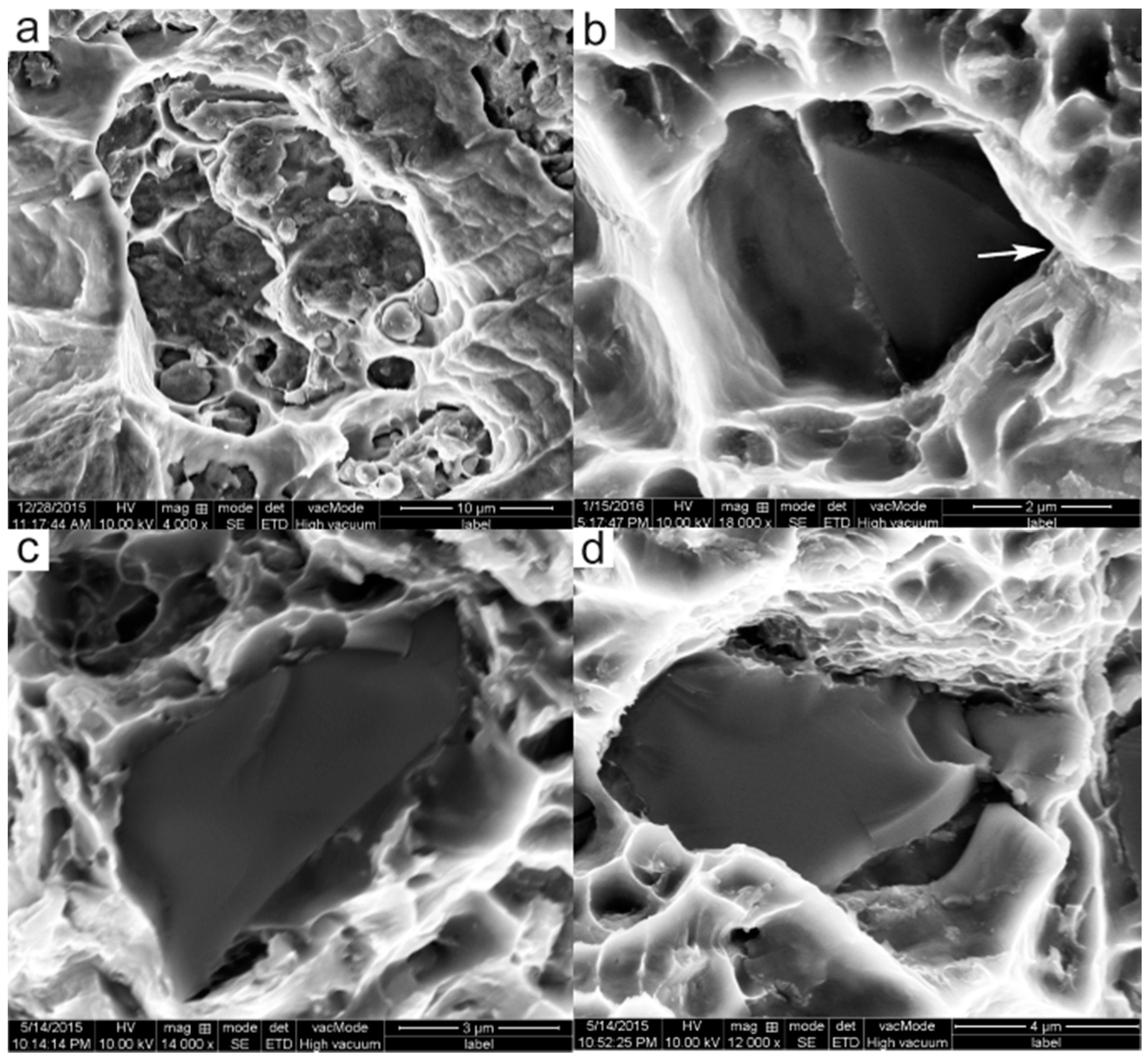
- The fracture surface of the PMC-6061 alloy is characterized by porosity features while that of the PTF-6061 alloy is quite compact. Both of the fractures belong to the intergranular mode. The fracture surface of the PTF-SiCp/6061Al composite is characterized by visible SiC particles and flat facets. The failure turns into the transgranular fracture mode.
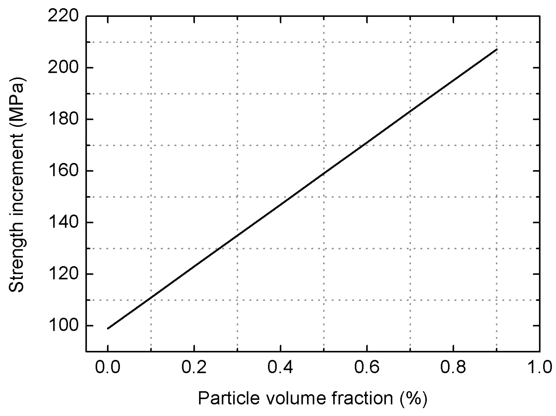
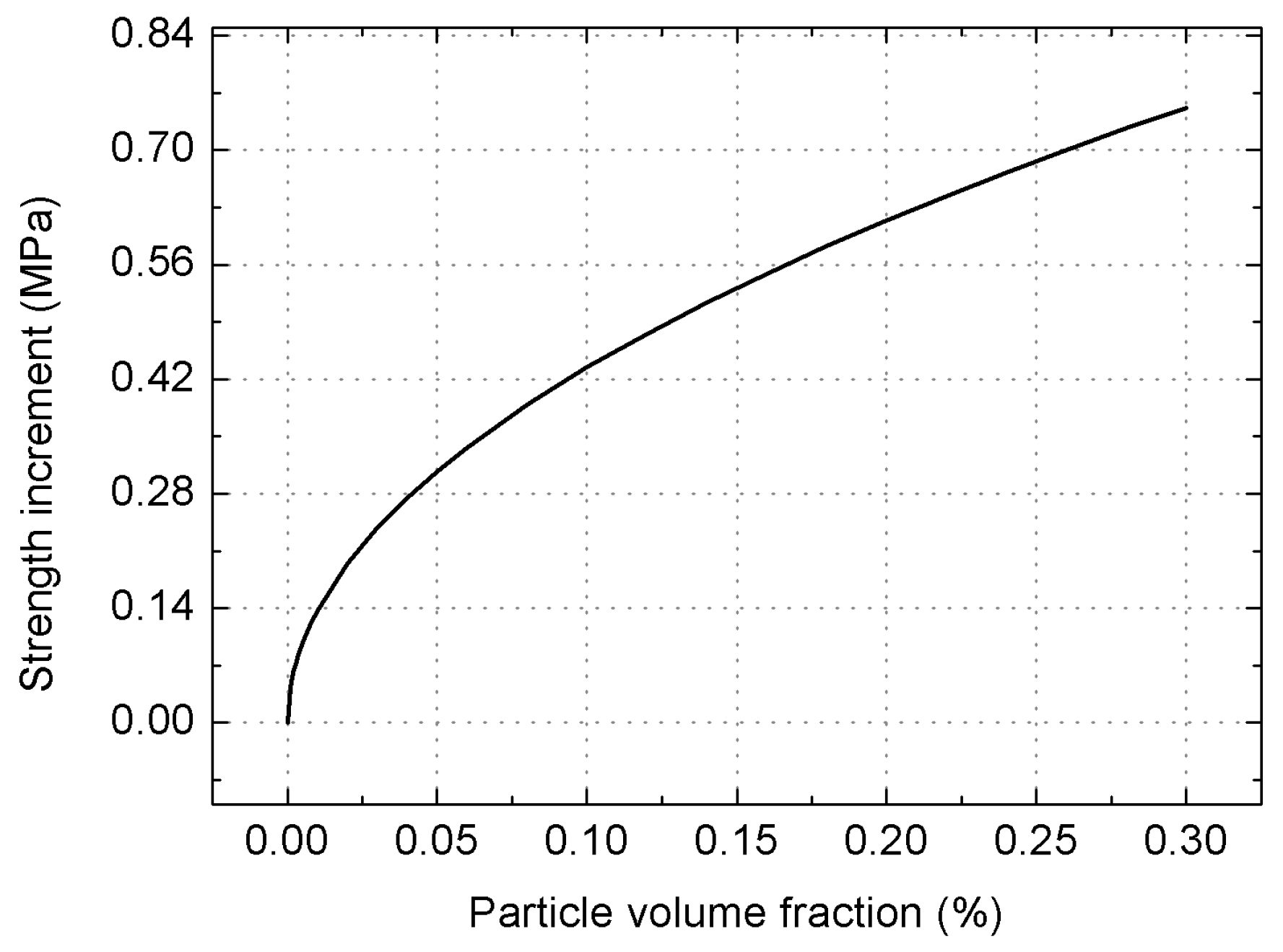
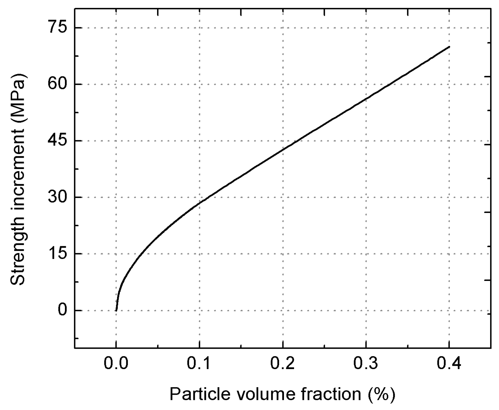
- The strength increment resulted from MSL model plays largest role in improving the yield strength of the composite. However, the strength increase obtained from the Orowan strengthening is quite minor owing to the micro size of the employed SiCp and the large inter-particle spacing.
- A modified model taking into consideration the SiCp failure fraction was proposed to calculate the yield strength of the PTF composite. The obtained theoretical results were quite consistent with the experimental data, revealing that the SiCp failure including SiCp/matrix debonding and SiCp cracking has a significant effect on the composite’s yield strength.
Acknowledgments
Author Contributions
Conflicts of Interest
References
- Liu, Z.Y.; Xiao, B.L.; Wang, W.G.; Ma, Z.Y. Elevated temperature tensile properties and thermal expansion of CNT/2009Al composites. Compos. Sci. Technol. 2012, 72, 1826–1833. [Google Scholar] [CrossRef]
- Sajjadi, S.A.; Ezatpour, H.R.; Beygi, H. Microstructure and mechanical properties of Al–Al2O3 micro and nano composites fabricated by stir casting. Mater. Sci. Eng. A 2011, 528, 8765–8771. [Google Scholar] [CrossRef]
- Hamedan, A.D.; Shahmiri, M. Production of A356-1 wt% SiC nanocomposite by the modified stir casting method. Mater. Sci. Eng. A 2012, 556, 921–926. [Google Scholar] [CrossRef]
- Lan, J.; Yang, Y.; Li, X. Microstructure and microhardness of SiC nanoparticles reinforced magnesium composites fabricated by ultrasonic method. Mater. Sci. Eng. A 2004, 386, 284–290. [Google Scholar] [CrossRef]
- Onat, A.; Akbulut, H.; Yilmaz, F. Production and characterisation of silicon carbide particulate reinforced aluminium–copper alloy matrix composites by direct squeeze casting method. J. Alloys Compd. 2007, 436, 375–382. [Google Scholar] [CrossRef]
- Hsu, C.W.; Chao, C.G. Effect of heat treatments on In-Situ Al2O3 /TiAl3 composites produced from squeeze casting of TiO2/A356 composites. Metall. Mater. Trans. B 2002, 33, 31–40. [Google Scholar] [CrossRef]
- Chao, Y.; He, F.H.; de los Reyes, M.; Long, Y.; Zhou, X.-T.; Xia, T.; Zhang, D.-L. Microstructures and Tensile Properties of Ultrafine-Grained Ni–(1–3.5) wt% SiCNP Composites Prepared by a Powder Metallurgy Route. Acta Metall. Sin. Engl. Lett. 2015, 7, 809–816. [Google Scholar]
- Ogel, B.; Gurbuz, R. Microstructural characterization and tensile properties of hot pressed Al–SiC composites prepared from pure Al and Cu powders. Mater. Sci. Eng. A 2001, 301, 213–220. [Google Scholar] [CrossRef]
- Li, P.; Chen, T.; Zhang, S.; Guan, R. Research on Semisolid Microstructural Evolution of 2024 Aluminum Alloy Prepared by Powder Thixoforming. Metals 2015, 5, 547–564. [Google Scholar] [CrossRef]
- Chen, Y.S.; Chen, T.J.; Zhang, S.Q.; Pu-Bo, L.I. Effects of processing parameters on microstructure and mechanical properties of powder-thixoforged 6061 aluminum alloy. Trans. Nonferrous Met. Soc. China 2015, 25, 699–712. [Google Scholar] [CrossRef]
- Chen, Y.S.; Chen, T.J.; Fu, W.; Li, P.B. Microstructural Evolution during Partial Remelting of 6061 Aluminum Bulk Alloy Prepared by Cold-Pressing of Alloy Powder. Adv. Mater. Res. 2013, 7, 20–24. [Google Scholar] [CrossRef]
- Zhang, X.Z.; Chen, T.J.; Qin, Y.H. Effects of solution treatment on tensile properties and strengthening mechanisms of SiCp/6061 Al composites fabricated by powder thixoforming. Mater. Des. 2016, 99, 182–192. [Google Scholar]
- Li, P.B.; Chen, T.J.; Zhang, S.Q.; Wang, Y.J. Effects of partial remelting on the microstructure evolution of SiCp/2024p aluminum composites prepared by alloy powder cold pressing. Spec. Cast. Nonferrous Alloys 2015, 35, 260–263. [Google Scholar]
- Chen, Y.S. The Research on Microstructure and Mechanical Properties of SiCp/6061 Al Matrix Composite Prepared by Powder Thixoforming. Master’s Thesis, Lanzhou University of Technology, Lanzhou, China, 20 April 2014. [Google Scholar]
- Belov, N.A.; Eskin, D.G.; Aksenov, A.A. Multicomponent Phase Diagrams: Applications for Commercial Aluminum Alloys; Elsevier: Amsterdam, The Netherlands, 2005. [Google Scholar]
- Cheng, F.L.; Chen, T.J.; Qi, Y.S.; Zhang, S.Q.; Yao, P. Effects of solution treatment on microstructure and mechanical properties of thixoformed Mg2Sip/AM60B composite. J. Alloys Compd. 2015, 636, 48–60. [Google Scholar] [CrossRef]
- Chen, T.; Jiang, X.; Huang, H.; Ma, Y.; Li, Y.; Hao, Y. Semisolid Microstructure of AZ91D Magnesium Alloy Refined by MgCO3. Int. J. Met. 2012, 6, 43–54. [Google Scholar] [CrossRef]
- Mitra, R.; Rao, V.S.C.; Maiti, R.; Chakraborty, M. Stability and response to rolling of the interfaces in cast Al–SiCp and Al–Mg alloy-SiCp composites. Mater. Sci. Eng. A 2004, 379, 391–400. [Google Scholar] [CrossRef]
- Zhang, S.; Chen, T.; Cheng, F.; Li, P. A Comparative Characterization of the Microstructures and Tensile Properties of As-Cast and Thixoforged in situ AM60B-10 vol% Mg2Sip Composite and Thixoforged AM60B. Metals 2015, 5, 457–470. [Google Scholar] [CrossRef]
- Flemings, M.C. Solidification processing. Metall. Mater. Trans. A 1974, 5, 2121–2134. [Google Scholar] [CrossRef]
- Fan, Z.; Fang, X.; Ji, S. Microstructure and mechanical properties of rheo-diecast (RDC) aluminium alloys. Mater. Sci. Eng. A 2005, 412, 298–306. [Google Scholar] [CrossRef]
- Burt, D.J. Direct thermal method: New process for development of globular alloy microstructure. Int. J. Cast. Met. Res. 2003, 16, 418–426. [Google Scholar]
- Tan, M.; Xin, Q.; Li, Z.; Zong, B.Y. Influence of SiC and Al2O3 particulate reinforcements and heat treatments on mechanical properties and damage evolution of Al-2618 metal matrix composites. J. Mater. Sci. 2001, 36, 2045–2053. [Google Scholar] [CrossRef]
- Song, M. Effects of volume fraction of SiC particles on mechanical properties of SiC/Al composites. Trans. Nonferrous Met. Soc. China 2009, 19, 1400–1404. [Google Scholar] [CrossRef]
- Chen, T.; Zhang, S.; Chen, Y.; Li, Y.; Ma, Y.; Hao, Y. Effects of Reheating Duration on the Microstructures and Tensile Properties of Thixoforged In Situ Mg2Sip/AM60B Composites. Acta. Metall. Sin. 2014, 27, 957–967. [Google Scholar] [CrossRef]
- Gubicza, J.; Nauyoks, S.; Balogh, L.; Labar, J.; Zerda, T.W.; Ungár, T. Influence of sintering temperature and pressure on crystallite size and lattice defect structure in nanocrystalline SiC. J. Mater. Res. 2007, 22, 1314–1321. [Google Scholar] [CrossRef] [Green Version]
- Zhang, Q.; Xiao, B.L.; Wang, W.G.; Ma, Z.Y. Reactive mechanism and mechanical properties of in situ composites fabricated from an Al–TiO2 system by friction stir processing. Acta Mater. 2012, 60, 7090–7103. [Google Scholar] [CrossRef]
- Wang, Z.; Prashanth, K.G.; Scudino, S.; Chaubey, A.K.; Sordelet, D.J.; Zhang, W.W.; Li, Y.Y.; Eckert, J. Tensile properties of Al matrix composites reinforced with in-situ devitrified Al84Gd6Ni7Co3 glassy particles. J. Alloys Compd. 2013, 586, S419–S422. [Google Scholar] [CrossRef]
- Wang, Z.; Tan, J.; Sun, B.A.; Scudino, S.; Prashanth, K.G.; Zhang, W.W.; Li, Y.Y.; Eckert, J. Fabrication and mechanical properties of Al-based metal matrix composites reinforced with Mg65Cu20Zn5Y10 metallic glass particles. Mater. Sci. Eng. A 2014, 4, 53–58. [Google Scholar] [CrossRef]
- Poirier, D.; Drew, R.A.L.; Trudeau, M.L.; Gauvin, R. Fabrication and properties of mechanically milled alumina/aluminum nanocomposites. Mater. Sci. Eng. A 2010, 527, 7605–7614. [Google Scholar] [CrossRef]
- Yan, S.J.; Dai, S.L.; Zhang, X.Y.; Yang, C.; Hong, Q.H.; Chen, J.Z.; Lin, Z.M. Investigating aluminum alloy reinforced by graphene nanoflakes. Mater. Sci. Eng. A 2014, 612, 440–444. [Google Scholar] [CrossRef]
- Rashad, M.; Pan, F.; Tang, A.; Asif, M. Effect of Graphene Nanoplatelets addition on mechanical properties of pure aluminum using a semi-powder method. Prog. Nat. Sci. Mater. Int. 2014, 3, 101–108. [Google Scholar] [CrossRef]
- Tabandeh-Khorshid, M.; Ferguson, J.B.; Schultz, B.F.; Kim, C.S.; Cho, K.; Rohatgi, P.K. Strengthening mechanisms of graphene and Al2O3 reinforced aluminum nanocomposites synthesized by room temperature milling. Mater. Des. 2015, 92, 79–87. [Google Scholar] [CrossRef]
- Tong, X.C.; Ghosh, A.K. Fabrication of in situ TiC reinforced aluminum matrix composites. J. Mater. Sci. 2001, 36, 4059–4069. [Google Scholar] [CrossRef]
- Nardone, V.C.; Prewo, K.M. On the strength of discontinuous silicon carbide reinforced aluminum composites. Scr. Metall. 1986, 20, 43–48. [Google Scholar] [CrossRef]
- Min, S.; Xie, C.Q.; He, Y.-H. Model of effects of particle failure on yield stress of SiC reinforced aluminum alloy composites. J. Nonferrous Met. 2010, 20, 244–249. [Google Scholar]
- Chen, K.H.; Fang, L.; Li, X.; Huang, D.W.; Fang, H.C. Influence of particle failure on strength of SiCp/Al composite. J. Cent. South Univ. Sci. Technol. 2008, 39, 493–499. [Google Scholar]


| Materials | Al (wt%) | Mg (wt%) | Si (wt%) |
|---|---|---|---|
| PMC alloy | 99.6 | 0.3 | 0.1 |
| PTF alloy | 98.5 | 1.0 | 0.5 |
| PTF composite | 98.0 | 0.8 | 1.2 |
© 2016 by the authors; licensee MDPI, Basel, Switzerland. This article is an open access article distributed under the terms and conditions of the Creative Commons Attribution (CC-BY) license (http://creativecommons.org/licenses/by/4.0/).
Share and Cite
Zhang, X.; Chen, T.; Qin, H.; Wang, C. A Comparative Study on Permanent Mold Cast and Powder Thixoforming 6061 Aluminum Alloy and Sicp/6061Al Composite: Microstructures and Mechanical Properties. Materials 2016, 9, 407. https://doi.org/10.3390/ma9060407
Zhang X, Chen T, Qin H, Wang C. A Comparative Study on Permanent Mold Cast and Powder Thixoforming 6061 Aluminum Alloy and Sicp/6061Al Composite: Microstructures and Mechanical Properties. Materials. 2016; 9(6):407. https://doi.org/10.3390/ma9060407
Chicago/Turabian StyleZhang, Xuezheng, Tijun Chen, He Qin, and Chong Wang. 2016. "A Comparative Study on Permanent Mold Cast and Powder Thixoforming 6061 Aluminum Alloy and Sicp/6061Al Composite: Microstructures and Mechanical Properties" Materials 9, no. 6: 407. https://doi.org/10.3390/ma9060407