
Shape Effect of Electrochemical Chloride Extraction in Structural Reinforced Concrete Elements Using a New Cement-Based Anodic System


Abstract
:1. Introduction
2. Experimental Program and Materials
2.1. Case Studies Carried out
- Case study 1
- application of ECE to a cylindrical specimen with Ti-RuO2 mesh anode.
- Case study 2
- application of ECE to a cylindrical specimen with graphite-cement paste anode.
- Case study 3
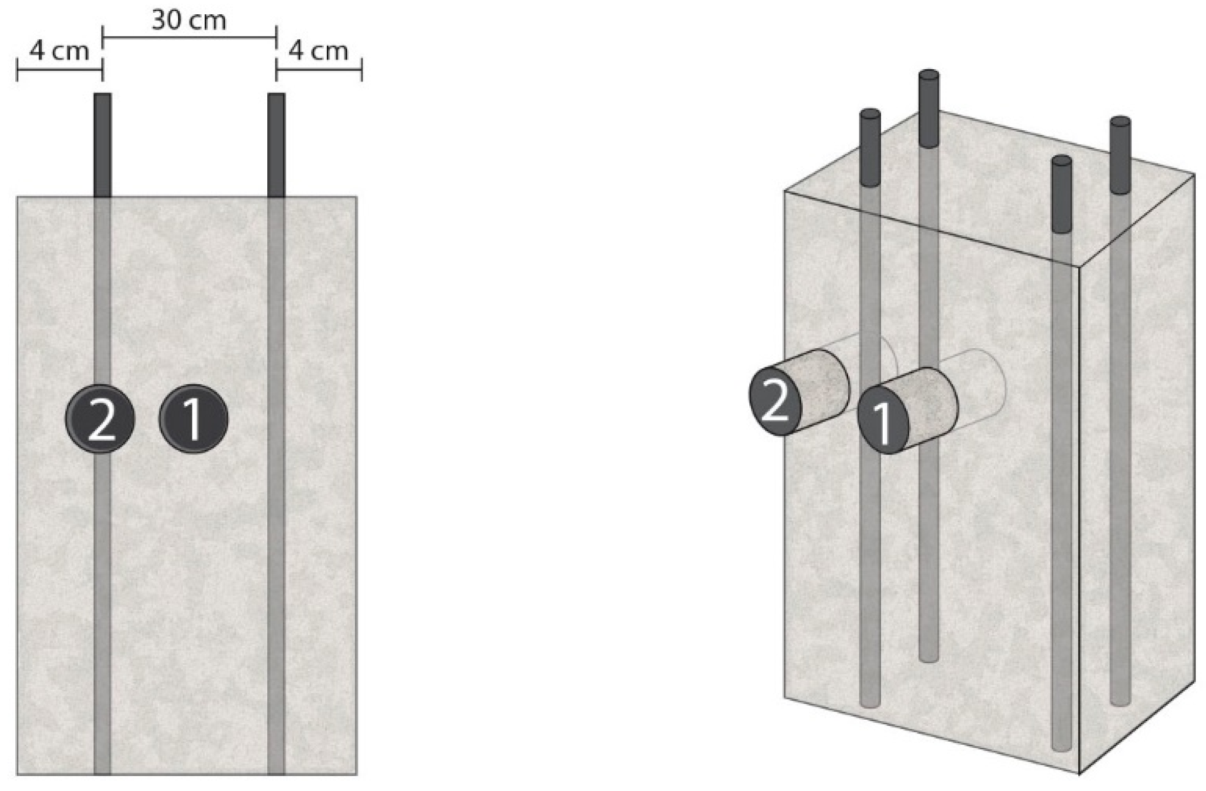
- application of ECE to a rectangular section specimen with Ti-RuO2 mesh anode. ECE efficiency is obtained for a core sample extracted on the center of the biggest face of the specimen.
- Case study 4
- application of ECE to a rectangular section specimen with Ti-RuO2 mesh anode. ECE efficiency is obtained for a core sample extracted on the cover zone of the rebar, just over the steel.
- Case study 5
- application of ECE to a rectangular section specimen with graphite-cement paste anode. ECE efficiency is obtained for a core sample extracted on the center of the biggest face of the specimen.
- Case study 6
- application of ECE to a rectangular section specimen with graphite-cement paste anode. ECE efficiency is obtained for a core sample extracted on the cover zone of the rebar, just over the steel.
2.2. Materials Used
2.2.1. Concrete

| Material | Dosage |
|---|---|
| Portland cement | 350 kg/m3 |
| w/c Ratio | 0.6 |
| Distilled water | 210 kg/m3 |
| Limestone aggregate 4/6 | 466 kg/m3 |
| Limestone aggregate 6/12 | 679 kg/m3 |
| Limestone sand | 630 kg/m3 |
| NaCl | 3.3% (2% Cl− relative to cement mass) |
2.2.2. Anodic Systems
| Material | Dosage (for 5 kg of paste) |
|---|---|
| Portland cement | 1.389 kg |
| Graphite powder | 1.389 kg |
| Distilled water | 2.222 kg |
2.2.3. Electrolyte and Way of Moistening
2.2.4. Electric Power Source
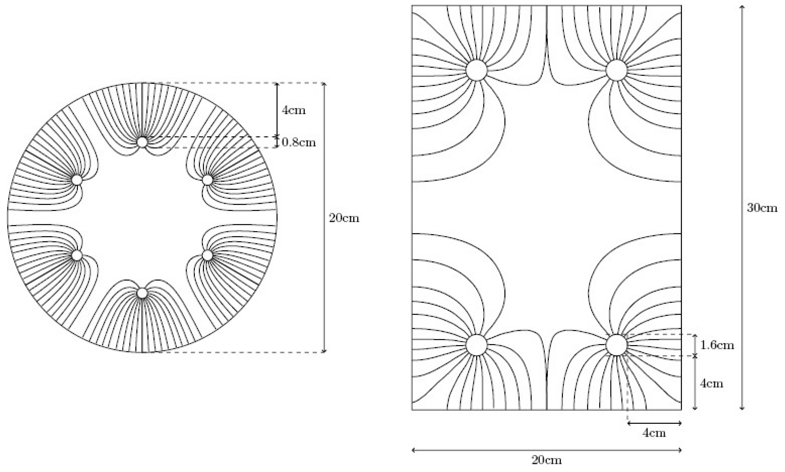
2.3. Assembly of Specimens
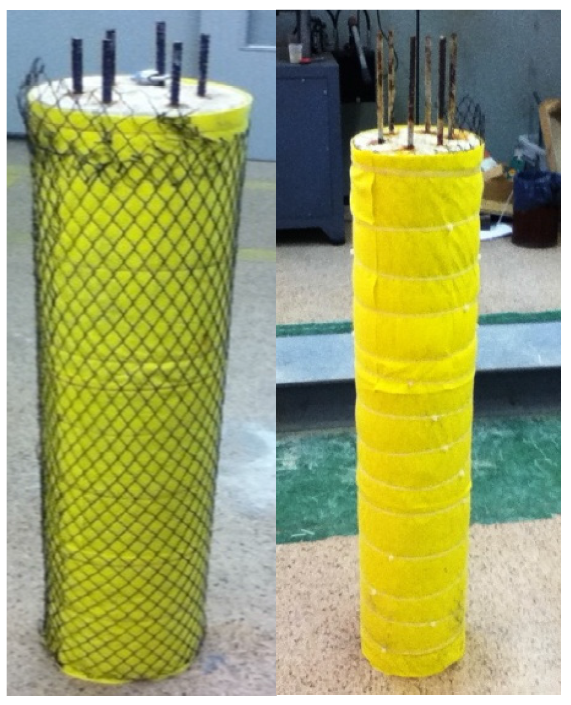
2.3.1. Specimens with Ti-RuO2 Mesh Anode System

2.3.2. Specimens with Graphite-Cement Paste (GCP) Anode System
2.4. ECE Applications
2.4.1. Specimens with Ti-RuO2 Mesh Anode System
2.4.2. Specimens with Graphite-Cement Paste (GCP) Anode System
- -
- a reduction in current density, but never under 1 A/m2; and
- -
- the inclusion of pauses along the treatment.
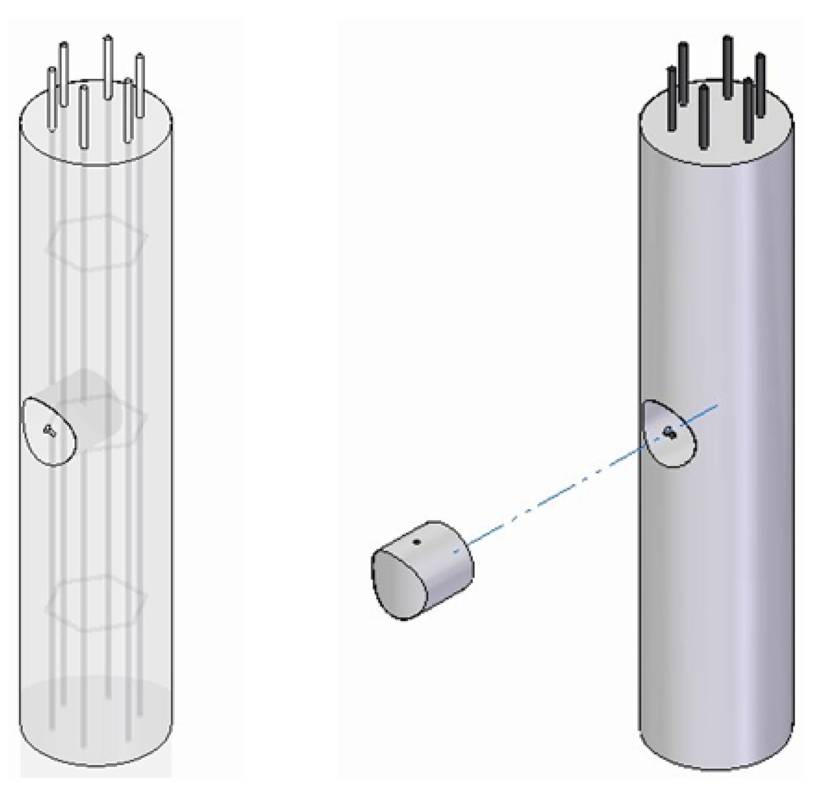
2.5. Extraction of Core Samples


2.6. Chloride Analysis
3. Results and Discussion
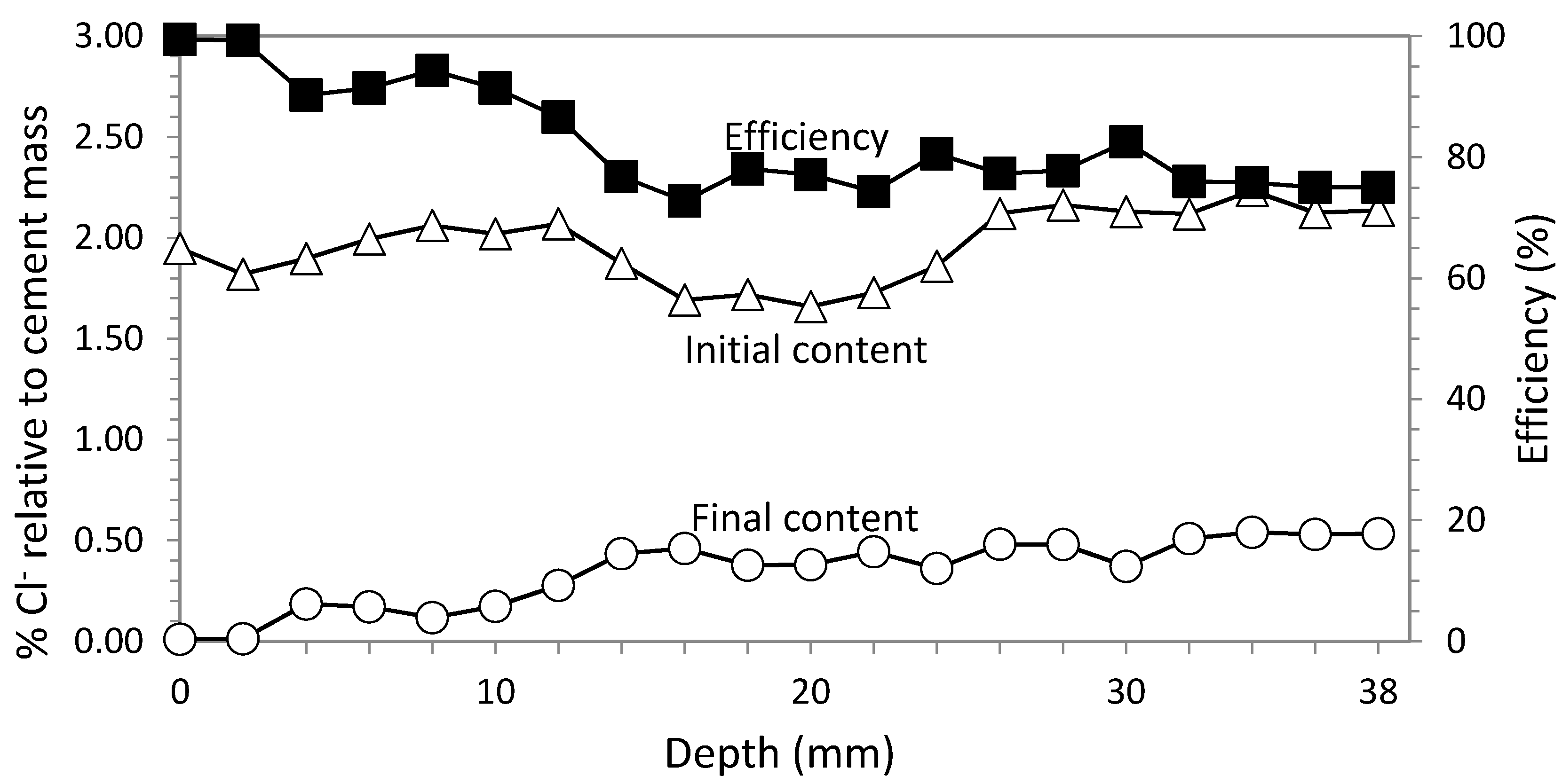
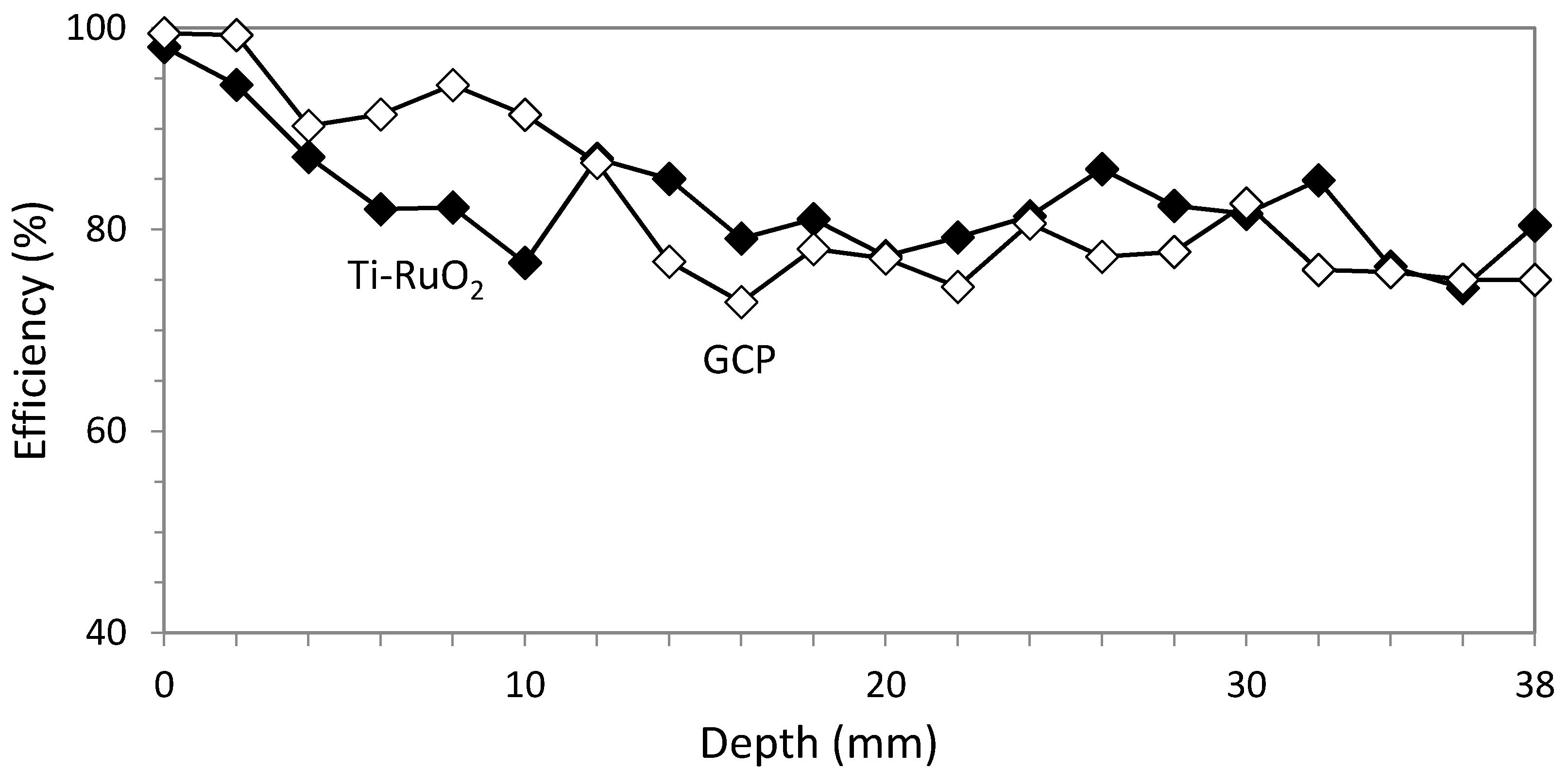
3.1. Study 1. Circular Section with Ti-RuO2 Mesh Based Anode System
3.2. Study 2. Circular Section with GCP Based Anode System


3.3. Rectangular Section with Ti-RuO2 Mesh Based Anode System
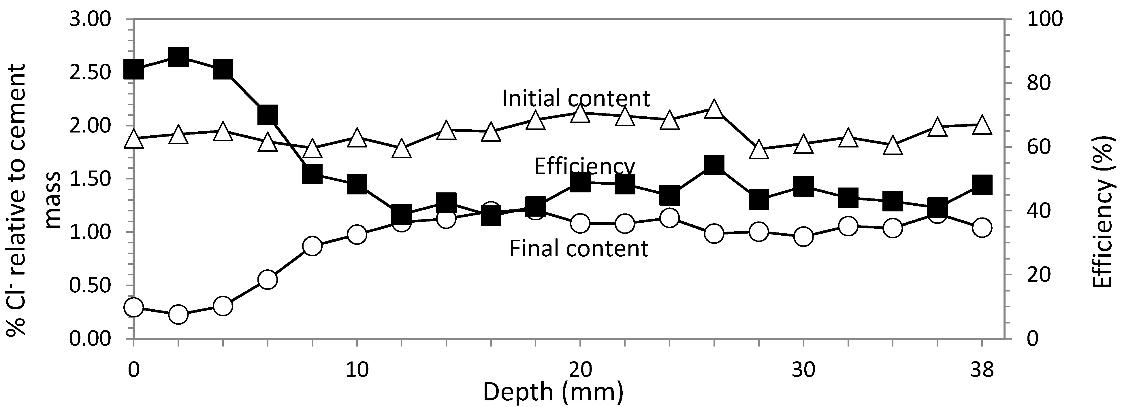
3.3.1. Study 3. Core Sample in the Center of the Biggest Face

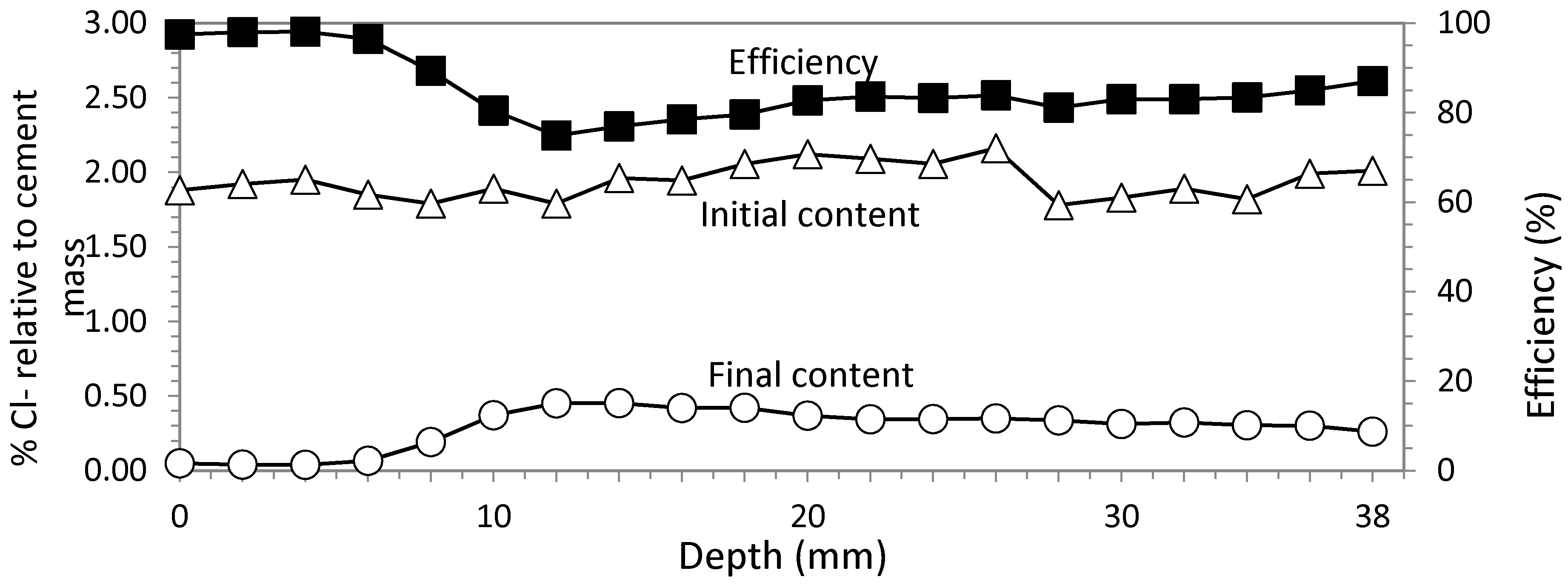
3.3.2. Study 4. Core Sample in the Concrete Cover Zone

3.4. Rectangular Section with GCP Based Anode System
3.4.1. Study 5. Core Sample in the Center of the Biggest Face
3.4.2. Study 6. Core Sample in the Concrete Cover Zone

| Study | Horizontal section shape of specimen | Anode system | Core sample location | Average efficiency (%) |
|---|---|---|---|---|
| 1 | Circular section | Ti-RuO2 mesh | 82.79 | |
| 2 | Circular section | GCP | 82.60 | |
| 3 | Rectangular section | Ti-RuO2 mesh | Center of the biggest face | 52.52 |
| 4 | Rectangular section | Ti-RuO2 mesh | Concrete cover over rebar | 85.22 |
| 5 | Rectangular section | GCP | Center of the biggest face | 64.38 |
| 6 | Rectangular section | GCP | Concrete cover over rebar | 76.15 |
4. Conclusions
Acknowledgments
Author Contributions
Conflicts of Interest
References
- Lankard, D.R.; Slater, J.E.; Hedden, W.A.; Niesz, D.E. Neutralization of Chloride in Concrete; Report No. FHWA-RD-76-60; Federal Highway Administration: Washington, DC, USA, 1975; pp. 1–143.
- Slater, J.E.; Lankard, D.R.; Moreland, P.L. Electrochemical Removal of Chlorides from Concrete Bridge Decks; Transportation Research Record No. 604; Transportation Research Board: Washington, DC, USA, 1976; pp. 6–15. [Google Scholar]
- Morrison, G.L.; Virmani, Y.P.; Stratton, F.W.; Gilliland, W.J. Chloride Removal and Monomer Impregnation of Bridge Deck Concrete by Electro-Osmosis; Report No. FHWA-Ks-RD-74-1; Kansas Department of Transportation, Federal Highway Administration (USA): Washington, DC, USA, 1976; p. 38.
- Tritthart, J. Electrochemical Chloride Removal: An Overview and Scientific Aspects; American Ceramic Society: Westerville, OH, USA, 1998; pp. 401–441. [Google Scholar]
- Mietz, J. Electrochemical Rehabilitation Methods for Reinforced Concrete Structures. A State of the Art Report; Book No 709; European Federation of Corrosion by the Institute of Materials: Graz, Austria, 1998. [Google Scholar]
- Andrade, C.; Castellote, M.; Alonso, C. An overview of electrochemical realkalisation and chloride extraction. In Proceedings of the 2nd Int. RILEM/CSIRO/ACRA Conference on Rehabilitation of Structures, Melbourne, Australia, 21–23 September 1998; Ho, D.W.S., Godson, I., Collins, F., Eds.; pp. 1–12.
- Bertolini, L.; Elsener, B.; Pedeferri, P.; Polder, R. Corrosion of Steel in Concrete; WYLEY-VCH Verlag GmbH & Co. KGaA: Veinheim, Germany, 2008; pp. 345–374. [Google Scholar]
- Vennesland, Ø.; Opsahl, O.A. Removal of Chlorides from Concrete. U.S.A & U.K. Patent 4832803, May 1989. [Google Scholar]
- Chung, D.D.L. Electrically conductive cement-based materials. Adv. Cem. Res. 2004, 16, 167–176. [Google Scholar] [CrossRef]
- Climent, M.A.; Sánchez de Rojas, M.J.; De Vera, G.; Garcés, P. Effect of type of anodic arrangements on the efficiency of electrochemical chloride removal from concrete. ACI Mater. J. 2006, 103, 243–250. [Google Scholar]
- Sánchez de Rojas, M.J.; Garcés, P.; Climent, M.A. Electrochemical extraction of chlorides from reinforced concrete: Variables affecting treatment efficiency. Mater. Constr. 2006, 56, 17–26. [Google Scholar]
- Garcés, P.; Andión, L.G.; Varga, I.; Catalá, G.; Zornoza, E. Corrosion of steel reinforcement in structural concrete with carbon material addition. Corros. Sci. 2007, 49, 2557–2566. [Google Scholar] [CrossRef]
- Ivorra, S.; Garcés, P.; Catalá, G.; Andión, L.G.; Zornoza, E. Effect of silica fume particle size on mechanical properties of short carbon fiber reinforced concrete. Mater. Des. 2010, 31, 1553–1558. [Google Scholar] [CrossRef]
- Garcés, P.; Zornoza, E.; Alcocel, E.G.; Galao, Ó.; Andión, L.G. Mechanical properties and corrosion of CAC mortars with carbon fibers. Constr. Build. Mater. 2012, 34, 91–96. [Google Scholar] [CrossRef]
- Garcés, P.; Fraile, J.; Vilaplana-Ortego, V.; Cazorla, D.; Alcocel, E.G.; Andión, L.G. Effects of carbon fibres on the mechanical properties and corrosion levels of reinforced Portland cement mortars. Cem. Concr. Res. 2005, 35, 324–331. [Google Scholar] [CrossRef]
- Fu, X.; Chung, V. Carbon fiber reinforced mortar as an electrical contact material for cathodic protection. Cem. Concr. Res. 1995, 25, 689–694. [Google Scholar] [CrossRef]
- Hou, J.; Chung, D.D.L. Cathodic protection of steel reinforced concrete facilitated by using carbon fiber reinforced mortar or concrete. Cem. Concr. Res. 1997, 27, 649–656. [Google Scholar] [CrossRef]
- DePeuter, F.; Lazzari, L. New conductive overlay for CP in concrete: Results of long term testing. Corrosion/93, paper nº 325. In Proceedings of the NACE Conference, Houston, TX, USA, 1993.
- Bertolini, L.; Bolzoni, F.; Pastore, T.; Pedeferri, P. Effectiveness of a conductive cementitious mortar anode for cathodic protection of steel in concrete. Cem. Concr. Res. 2004, 34, 681–694. [Google Scholar] [CrossRef]
- Pérez, A.; Climent, M.A.; Garcés, P. Electrochemical extraction of chlorides from reinforced concrete using a conductive cement paste as the anode. Corros. Sci. 2010, 52, 1576–1581. [Google Scholar] [CrossRef]
- Cañón, A.; Garcés, P.; Climent, M.A.; Carmona, J.; Zornoza, E. Feasibility of electrochemical chloride extraction from structural reinforced concrete using a sprayed conductive graphite powder-cement as anode. Corros. Sci. 2013, 77, 128–134. [Google Scholar] [CrossRef]
- Hope, B.B.; Ihekwaba, V。; Hansson, C.M. Influence of Multiple Rebar Mats on Electrochemical Removal of Chloride from concrete. Mater. Sci. Forum 1995, 192–194, 993–890. [Google Scholar]
- Ihekwaba, N.M.; Hope, N.M.; Hansson, C.M. Structural shape effect on rehabilitation of vertical concrete structures by ECE technique. Cem. Concr. Res. 1996, 26, 165–175. [Google Scholar] [CrossRef]
- Garcés, P.; Sánchez de Rojas, M.J.; Climent, M.A. Effect of the reinforcement bar arrangement on the efficiency of electrochemical chloride removal technique applied to the reinforced concrete structures. Corros. Sci. 2006, 48, 531–545. [Google Scholar] [CrossRef]
- Comisión Permanente del Hormigón, Ministerio de Fomento. Instrucción de Hormigón Estructural EHE-08 (Spanish Code on Structural Concrete EHE-08); Comisión Permanente del Hormigón, Ministerio de Fomento: Madrid, Spain, 2008; (Only available in Spanish). [Google Scholar]
- BSI. Electrochemical Re-Alkalization and Chloride Extraction Treatments for Reinforced Concrete—Part 2: Chloride Extraction; CEN/TS 14038-2:2011; BSI: London, UK, 2011. [Google Scholar]
- Elsener, B.; Molina, M.M.; Böhni, H. The Electrochemical Removal of Chlorides from Reinforced Concrete. Corros. Sci. 1993, 35, 1563–1570. [Google Scholar] [CrossRef]
- Polder, R.B.; Walker, R.; Page, C.L. Electrochemical chloride removal tests of concrete cores from a coastal structure. In Proceedings of the International Conference on Corrosion and Corrosion Protection of Steel in Concrete, University of Sheffield, Sheffield, UK, 24–28 July 1994.
- Vennesland, Ø.; Climent, M.A.; Andrade, C. Recommendation of RILEM TC 178-TMC: Testing and modeling chloride penetration in concrete. Methods for obtaining dust samples by means of grinding concrete in order to determine the chloride concentration profile. Mater. Struct. 2013, 46, 337–337. [Google Scholar]
- Climent, M.A.; Viqueira, E.; de Vera, G.; López, M.M. Analysis of acid-soluble chloride in cement, mortar and concrete by potentiometric titration without filtration steps. Cem. Concr. Res. 1999, 29, 893–898. [Google Scholar] [CrossRef]
- Climent, M.A.; de Vera, G.; Viqueira, E.; López, M.M. Generalization of the possibility of eliminating the filtration step in the determination of acid-soluble chloride content in cement and concrete by potentiometric titration. Cem. Concr. Res. 2004, 34, 2291–2295. [Google Scholar] [CrossRef]
© 2015 by the authors; licensee MDPI, Basel, Switzerland. This article is an open access article distributed under the terms and conditions of the Creative Commons Attribution license (http://creativecommons.org/licenses/by/4.0/).
Share and Cite
Carmona, J.; Climent, M.-Á.; Antón, C.; De Vera, G.; Garcés, P. Shape Effect of Electrochemical Chloride Extraction in Structural Reinforced Concrete Elements Using a New Cement-Based Anodic System. Materials 2015, 8, 2901-2917. https://doi.org/10.3390/ma8062901
Carmona J, Climent M-Á, Antón C, De Vera G, Garcés P. Shape Effect of Electrochemical Chloride Extraction in Structural Reinforced Concrete Elements Using a New Cement-Based Anodic System. Materials. 2015; 8(6):2901-2917. https://doi.org/10.3390/ma8062901
Chicago/Turabian StyleCarmona, Jesús, Miguel-Ángel Climent, Carlos Antón, Guillem De Vera, and Pedro Garcés. 2015. "Shape Effect of Electrochemical Chloride Extraction in Structural Reinforced Concrete Elements Using a New Cement-Based Anodic System" Materials 8, no. 6: 2901-2917. https://doi.org/10.3390/ma8062901