Article

Direct Ink Writing of Three-Dimensional (K, Na)NbO3-Based Piezoelectric Ceramics

1
State Key Laboratory of New Ceramics and Fine Processing, School of Materials Science and Engineering, Tsinghua University, Beijing 100084, China
2
Research Institute for Advanced Materials, Graduate School at Shenzhen, Tsinghua University, Shenzhen 518055, China
*
Author to whom correspondence should be addressed.
Materials 2015, 8(4), 1729-1737; https://doi.org/10.3390/ma8041729
Submission received: 11 March 2015 / Revised: 31 March 2015 / Accepted: 8 April 2015 / Published: 14 April 2015

Abstract

:
A kind of piezoelectric ink was prepared with Li, Ta, Sb co-doped (K, Na)NbO3 (KNN) powders. Piezoelectric scaffolds with diameters at micrometer scale were constructed from this ink by using direct ink writing method. According to the micro-morphology and density test, the samples sintered at 1100 °C for 2 h have formed ceramics completely with a high relative density of 98%. X-ray diffraction (XRD) test shows that the main phase of sintered samples is orthogonal (Na0.52K0.4425Li0.0375)(Nb0.87Sb0.07Ta0.06)O3. The piezoelectric constant d33 of 280 pC/N, dielectric constant ε of 1775, remanent polarization Pr of 18.8 μC/cm2 and coercive field Ec of 8.5 kV/cm prove that the sintered samples exhibit good electrical properties. The direct ink writing method allows one to design and rapidly fabricate piezoelectric structures in complex three-dimensional (3D) shapes without the need for any dies or lithographic masks, which will simplify the process of material preparation and offer new ideas for the design and application of piezoelectric devices.

1. Introduction

Environmentally-friendly lead-free piezoelectric ceramics have attracted much attention in recent years. In 2004, Saito et al. [1] reported a big breakthrough of a high d33 (416 pC/N) in the Li+-, Ta5+-, and Sb5+-modified (K, Na)NbO3 (KNN) textured ceramics as a promising candidate for lead-free piezoelectric ceramics. Up to now, studies about KNN are focusing on the improvement of the materials and the structure designs. Material improvement mainly concerns the substitution behavior [2,3], phase transitional behavior [4,5,6,7] and adulteration of the materials [8,9,10,11,12]. For the structure design refers to the KNN-based piezoelectric devices such as the sensors, transducers and actuators [13,14,15,16,17], most of which are fabricated by the 1–3 KNN composite [18,19,20] or the single crystalline KNN nanostructures [21,22,23,24]. Few works about the three-dimensional (3D) KNN structures, however, have been reported in the fabrication of piezoelectric devices. Direct ink writing (DIW) technique is a powerful fabrication method in building 3D KNN piezoelectric scaffolds due to its favorable performance. In this method, subtle 3D KNN architectures can be constructed without the need for any dies or lithographic masks [25], which is more convenient than the dice and fill method to fabricate 1–3 type KNN products [26]. DIW shows a potential for application in catalytic materials [27], tissue engineering [28] and especially the composites [29].
In this paper, we prepared methyl methacrylate based suspensions of KNN inks and fabricated 3D piezoelectric woodpile structures with various structural parameters by using DIW technique. The phase composition, the microstructure and the piezoelectric parameters of the sintered samples were observed.

2. Experimental Section

The KNN-based powders with enhanced piezoelectricity by co-additive of Li, Sb, and Ta were prepared by a two-step calcining and ball milling route. The average particle size of the powder was about 0.5 μm with the specific surface area of 10.1 m2/g. Methyl methacrylate (AR, Beijing Yili Fine Chemicals, Beijing, China) and pentaerythritol three acrylate (Alfa Aesar, Beijing, China) were mixed as a solvent. A certain amount of KNN powders were added into the mixture with ultrasound treatment and the final suspension had a solid content fraction of 56 wt%. The plot of viscosity as a function of the shear stress and the plot of shear stress on shear rate were measured by a controlled stress rheometer (Physica MRC 300 Modular Compact Rheometer, Physica Paar, Berlin, Germany) under the pressure from 1 Pa to 1000 Pa at room temperature.
The direct ink writing equipment (A3200, Aerotech Inc., Pittshurgh, PA, USA) consists of three parts (Figure 1). The first one is the computer-controlled system which designs the structure and translates the mobile paths into code languages. The second one is the 3D motion platform which can move under the instruction of the computer. The last one is the extrusion system which can eject the inks under a proper pressure. In this experiment, we designed three woodpile structures with different sizes and changed those into code languages. The 3D platform constructed all the KNN woodpile structures after receiving the motion instructions.
Figure 1. Experimental set-up for the direct write printing process.
Materials 08 01729 g001
Those green samples were sintered at varying temperatures for 2 h with a heating rate of 3 °C/min. The macrostructures of the samples were characterized by optical microscope (AXio Imager.Z1m, Carl Zeiss Shanghai Co. Ltd., Shanghai, China). The microstructures of the sintered samples were analyzed by using scanning electron microscopy (Leo-1530, Oberkochen, Germany). The density of the sintered sample was measured by the Archimedes technique with deionized water as the suspension fluid. The dielectric properties were measured by an impedance analyzer (HP4278A, Santa Clara, CA, USA) and the d33 measurements were performed by using a ZJ-3A quasi-static d33 tester (Institute of Acoustics, Chinese Academy of Sciences, Beijing, China). The hysteresis loop was tested by a ferroelectric tester (RT 6000HVA, Radiant Technologies Inc., Albuquerque, NM, USA) under a maximum electric field of 2.5 kV/mm.

3. Results and Discussion
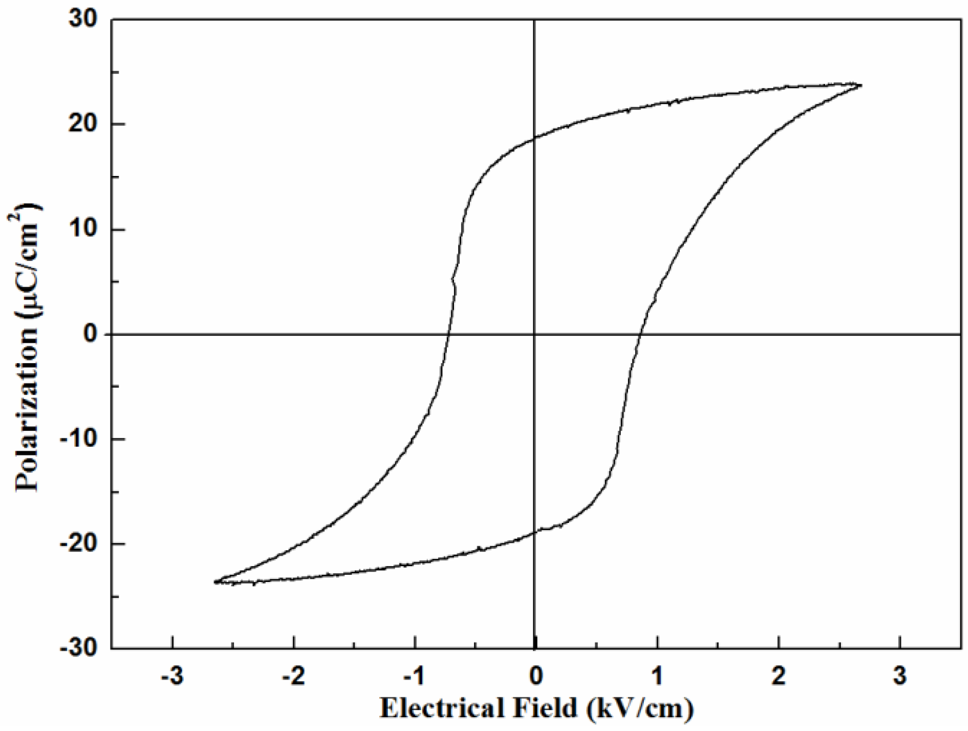
Nanosize KNN powders with little soft-agglomerates is shown in Figure 2a. The X-ray diffraction (XRD) pattern of the KNN powders (Figure 2b) shows the main phase is (Na0.52K0.4425Li0.0375)(Nb0.87Sb0.07Ta0.06)O3 which is prepared by the co-additive of Li, Sb, and Ta in the (K, Na)NbO3 powders.
Figure 2. (a)The SEM image of the KNN powders; (b) the XRD pattern of the KNN powders.
Materials 08 01729 g002
Figure 3a shows the plot of shear stress as a function on shear rate, which is close to that of the classic shear thinning fluid. When the shear stress less than 15 Pa, the ink shows an elastic deformation behavior, and the deformation can be restored after unloading (Figure 3b). Then the viscosity decreases rapidly and experiences a plastic deformation to reach a steady state at 50 Pa. This deformation type cannot be restored after unloading. The changing trend of the plot indicates that the ink has a shear-thinning behavior.
Figure 3. (a) Plot of the shear stress as a function of shear rate; (b) plot of the viscosity as a function of shear stress.
Materials 08 01729 g003
The optimum solid content of the ink is related to the specific surface area of the original powders, and the KNN ink with a solid content fraction of 56 wt% is beneficial for the fabrication process and can be sintered with a high relative density. For example, the ink formed by TiO2 nanoparticle powders (specific surface area of 50 m2/g) has a proper solid content of 42.5 wt% [30]. The ink formed by PLZT powders (specific surface area of 4.735 m2/g) has an appropriate solid content about 70 wt% [31]. Both of the above mentioned two inks can be sintered with a high relative density. In this paper, we use the KNN powders with a specific surface area of 10.1 m2/g to form the ink with a final solid content of 56 wt%. We can conclude that the powders with a larger specific surface area can be developed to an ink with a smaller solid content fraction.
Here, we design 3D KNN woodpile structures with various shape sizes, filament diameters and rod-to-rod distances. Figure 4a shows the top view of the three structures with shape sizes of 10 mm × 10 mm or 12 mm × 12 mm. Figure 4b shows the sample with the filament diameter of 400 μm and rod-to-rod distance of 1 mm. Figure 4c shows the sample with the filament diameter of 250 μm and rod-to-rod distance of 600 μm. Figure 4d shows the sample with the filament diameter of 300 μm and rod-to-rod distance of 500 μm. It is obvious that the direct ink writing (DIW) method has an advantage in the structure design and size precision control.
A series of sintered experiments have been performed to find out the optimum sintering process. We designed three sintering temperatures, namely: 1050 °C, 1100 °C and 1130 °C. Figure 5a shows the sample sintered in 1050 °C for 2 h, we can see that this sample has not been sintered completely with the non-uniform grain size and lots of pores. Figure 5c shows the SEM image of the sample sintered under 1130 °C for 2 h, which is over sintered with an abnormal grain growth. From Figure 5b we can conclude that the KNN sample sintered at 1100 °C for 2 h has a better performance with the uniform grain size and less pores. The density of the sintered sample was measured by the Archimedes method with deionized water as the suspension fluid. Moreover, the testing density is 4.52 g/cm3, while the theoretical density of KNN is about 4.60 g/cm3. The relative density (98%) is the ratio of the testing density and the theoretical density. Figure 5d shows the top view of the sample (on the right-hand side of Figure 4a) sintered at 1100 °C for 2 h, which shows that the deformation did not occur during the sintering process.
Figure 4. Optical images of the woodpile structures: (a) top view of three samples with different sizes; (b) 10 mm × 10 mm sample with a filament diameter of 400 μm; (c) 12 mm × 12 mm sample with a filament diameter of 250 μm; (d) 10 mm × 10 mm sample with filament a diameter of 300 μm.
Materials 08 01729 g004
Figure 5. SEM photos of KNN samples sintered to varying maximum temperatures: (a) 1050 °C; (b) 1100 °C; (c) 1130 °C; (d) the top view of the sintered 10 mm × 10 mm sample.
Materials 08 01729 g005
Figure 6 shows the XRD pattern of the KNN sample sintered at 1100 °C. The sintered sample agrees well with the origin powders, indicating that no significant phase transition occurred during the sintering process.
The sintered sample with the original size of 10 mm×10 mm and filament diameter of 400 μm was printed with the low temperature silver paste on the top and bottom surface and covered with aluminum foil. Then the sample was poled at 2.5 kV/mm for 20 min in a silicone oil bath at 100 °C. The hysteresis loop was tested under a maximum electric field of 2.5 kV/mm (Figure 7), and the value of remanent polarization Pr and coercive field Ec were gained. Table 1 shows the dielectric and piezoelectric properties of the sintered 3D KNN sample. We can see that sintered sample has good electrical properties with piezoelectric constant d33 of 280 pC/N, dielectric constant of 1775, remanent polarization Pr of 18.8 μC/cm2 and coercive field Ec of 8.5 kV/cm.
Figure 6. XRD pattern of the sample sintered at 1100 °C.
Materials 08 01729 g006
Figure 7. The hysteresis loop of the sintered KNN sample.
Materials 08 01729 g007
Table 1. Dielectric and piezoelectric properties of the sintered KNN sample.
Electrical propertiesε330d33 (pC/N)Pr (μC/cm2)Ec (kV/cm)
KNN sample177528018.88.5

4. Conclusions

We prepared KNN woodpile structures with a relatively high piezoelectric constant by using direct ink writing method along with the ink methyl methacrylate based suspensions of KNN. Three woodpile structures with various shape sizes, filament diameters and rod-to-rod distances have been constructed. Samples sintered in 1100 °C for 2 h have a relative density of 98%. The piezoelectric constant d33 of 280 pC/N, dielectric constant ε of 1775, remanent polarization Pr of 18.8 μC/cm2 and coercive field Ec of 8.5 kV/cm show that the sintered samples exhibit good electrical properties. Compared with the other methods such as dice and fill method and injection molding, the direct ink writing method allows one to design and rapidly fabricate piezoelectric structures in complex 3D shapes without the need for any dies or lithographic masks, which will simplify the processing of the material preparation and offer ideas for the design and application of new piezoelectric devices.

Acknowledgments

This work was financially supported by National Science Foundation of China (Grant Nos. 50902081, 61077029 and 51032003), National 973 project (Grant No. 2009CB623304), Shenzhen Science and technology plan under JSE201007200050A, and by the Project of Cooperation from Industry, Education and Academy supported by Guangdong Province (Grant No. 2009A090100021).

Author Contributions

Longtu Li and Bo Li provide some theoretical guidances about KNN. Renlong Gao offers some experimental guidances on this paper. Yayun Li wrote the manuscript.

Conflicts of Interest

The authors declare no conflict of interest.

References

  1. Saito, Y.; Takao, H.; Tani, T.; Nonoyama, T.; Takatori, K.; Homma, T.; Nagaya, T.; Nakamura, M. Lead-free piezoceramics. Nature 2004, 432, 84–87. [Google Scholar] [CrossRef] [PubMed]
  2. Ha, J.; Ryu, J.; Lee, H. Substitution behavior of x(Na0.5K0.5)NbO3-(1−x)BaTiO3 ceramics for multilayer ceramic capacitors by a near edge X-ray absorption fine structure analysis. Appl. Phys. Lett. 2014, 104, 262904:1–262904:4. [Google Scholar]
  3. Lu, L.; Gong, Y.Q.; Gong, L.J.; Dong, H.D.; Dong, H.; Yi, X.F.; Zheng, X.J. Low-temperature hydro/solvothermal synthesis of Ta-modified K0.5Na0.5NbO3 powders and piezoelectric properties of corresponding ceramics. Mater. Des. 2012, 33, 362–366. [Google Scholar]
  4. Toshio, K.; Yuan, Y.; Fumito, S. Mechanisms of texture development in lead-free piezoelectric ceramics with perovskite structure made by the templated grain growth process. Materials 2010, 3, 4965–4978. [Google Scholar] [CrossRef]
  5. Dai, Y.J.; Zhang, X.W.; Zhou, G.Y. Phase transitional behavior in K0.5Na0.5NbO3-LiTaO3 ceramics. Appl. Phys. Lett. 2007, 90, 262903:1–262903:3. [Google Scholar]
  6. Zuo, R.Z.; Fu, J.; Lv, D.Y.; Liu, Y. Antimony tuned rhombohedral-orthorhombic phase transition and enhanced piezoelectric properties in sodium potassium niobate. J. Am. Ceram. Soc. 2010, 93, 2783–2787. [Google Scholar] [CrossRef]
  7. Fisher, J.G.; Rout, D.; Moon, S.K.; Kang, S.J.L. Structural changes in potassium sodium niobate ceramics sintered in different atmospheres. J. Alloys Compd. 2009, 479, 467–472. [Google Scholar] [CrossRef]
  8. Fu, J.; Zuo, R.Z.; Wang, X.H.; Li, L.T. Phase transition characteristics and piezoelectric properties of compositionally optimized alkaline niobate based ceramics. J. Alloys Compd. 2009, 486, 790–794. [Google Scholar] [CrossRef]
  9. Wang, X.P.; Wu, J.G.; Xiao, D.Q.; Zhu, J.G.; Cheng, X.J.; Zheng, T.; Zhang, B.Y.; Lou, X.J.; Wang, X.J. Giant piezoelectricity in potassium-sodium niobate lead-free ceramics. J. Am. Ceram. Soc. 2014, 136, 2905–2910. [Google Scholar]
  10. Lee, Y.; Yoo, J.; Lee, K.; Kim, I.; Song, J.; Park, Y.W. Dielectric and piezoelectric characteristics of the non-stoichiometric (Na, K)NbO3 ceramics doped with CuO. J. Alloys Compd. 2010, 506, 872–876. [Google Scholar] [CrossRef]
  11. Wang, Y.L.; Damjanovic, D.; Klein, N.; Setter, N. High-temperature instability of Li- and Ta- modified (K, Na)NbO3 piezoceramics. J. Am. Ceram. Soc. 2008, 91, 1962–1970. [Google Scholar] [CrossRef]
  12. Ming, B.Q.; Wang, J.F.; Qi, P.; Zang, G.Z. Piezoelectric properties of (Li, Sb, Ta) modified (Na, K)NbO3 lead-free ceramics. J. Appl. Phys. 2007, 101, 054103:1–054103:4. [Google Scholar] [CrossRef]
  13. Kwok, K.W.; Hon, S.F.; Lin, D. Lead-free self-focused piezoelectric transducers for viscous liquid ejection. Sens. Actuators A Phys. 2011, 168, 168–171. [Google Scholar] [CrossRef]
  14. Wu, D.W.; Chen, R.M.; Zhou, Q.F.; Shung, K.K.; Lin, D.M.; Chan, H.L.W. Lead-free KNLNT piezoelectric ceramics for high-frequency ultrasonic transducer application. Ultrasonic 2009, 49, 395–398. [Google Scholar] [CrossRef]
  15. Hong, J.; Yoo, J.; Lee, K.; Lee, S.; Song, H. Characteristics of acoustic emission sensor using lead-free (LiNaK)(NaTaSb)O3 ceramics for fluid leak detection at power plant valves. Jpn. J. Appl. Phys. 2008, 47, 2192–2194. [Google Scholar] [CrossRef]
  16. Oh, Y.; Noh, J.; Yoo, J.; Kang, J.; Hwang, L.; Hong, J. Dielectric and piezoelectric properties of CeO2-added Nonstoichiometric (Na0.5K0.5)0.97(Nb0.96Sb0.04)O3 ceramics for piezoelectric energy harvesting device applications. IEEE Trans. Ultrason. Ferroelectr. Freq. Control 2011, 58, 1860–1866. [Google Scholar]
  17. Lee, T.; Kwok, K.W.; Li, H.L.; Chan, H.L.W. Lead-free alkaline niobate-based transducer for ultrasonic wirebonding applications. Sens. Actuators A Phys. 2009, 150, 267–271. [Google Scholar] [CrossRef]
  18. Shen, Z.Y.; Li, J.F.; Chen, R.M.; Zhou, Q.F.; Shung, K.K. Microscale 1–3 type (Na, K)NbO3-based Pb-free piezocomposites for high-frequency ultrasonic transducer applications. J. Am. Ceram. Soc. 2011, 94, 1346–1349. [Google Scholar] [CrossRef] [PubMed]
  19. Zhou, D.; Lam, K.H.; Chen, Y.; Zhang, Q.H.; Chiu, Y.C.; Luo, H.; Dai, J.Y.; Chan, H.L.W. Lead-free piezoelectric single crystal based 1–3 composites for ultrasonic transducer applications. Sens. Actuators A Phys. 2012, 182, 95–100. [Google Scholar] [CrossRef]
  20. Xu, Y.; Li, J.F.; Ma, J.; Nan, C.W. Magnetoelectricity of lateral 1–3 type composites with CoFe2O4 ferromagnetic microstrips embedded in (K, Na)NbO3-based piezoelectric substrate. J. Appl. Phys. 2011, 110, 044104:1–044104:4. [Google Scholar]
  21. Li, L.H.; Deng, J.X.; Chen, J.; Yu, R.B.; Qiao, L.J.; Xing, X.R. Piezoelectric and ferroelectric properties of 0.96(Na,K)(Nb0.9Ta0.1)O3–0.04LiSbO3 ceramics synthesized by molten salt method. J. Alloys Compd. 2009, 471, 428–431. [Google Scholar]
  22. Urban, J.J.; Spanier, J.E.; Lian, O.Y.; Yun, W.S.; Park, H. Single-crystalline barium titanate nanowires. Adv. Mater. 2003, 15, 423–426. [Google Scholar] [CrossRef]
  23. Farooq, M.U.; Fisher, J.G. Growth of (K0.5Na0.5)NbO3SrTiO3 lead-free piezoelectric single crystals by the solid state crystal growth method and their characterization. Ceram. Int. 2014, 40, 3199–3207. [Google Scholar]
  24. Hou, Y.D.; Hou, L.; Zhang, T.T.; Zhu, N.K.; Wang, H.; Yan, H. (Na0.8K0.2)0.5Bi0.5TiO3 nanowires: Low-temperature sol-gel-hydrothermal synthesis and densification. J. Am. Ceram. Soc. 2007, 90, 1738–1743. [Google Scholar]
  25. Lewis, J.A. Direct-write assembly of ceramics of colloidal inks. Curr. Opin. Solid State Mater. Sci. 2002, 6, 245–250. [Google Scholar] [CrossRef]
  26. Li, J.F.; Wang, K.; Zhu, F.Y.; Cheng, L.Q.; Yao, F.Z. (K, Na)NbO3-based lead-free piezoceramics: Fundamental aspects, processing technologies, and remaining challenges. J. Am. Ceram. Soc. 2013, 96, 3677–3696. [Google Scholar] [CrossRef]
  27. Li, Y.Y.; Li, B.; Li, L.T. Fabrication of 3D photocatalytic α-Fe2O3 structure using direct ink writing method. Mod. Phys. Lett. B 2014, 28, 1450051. [Google Scholar] [CrossRef]
  28. Simon, J.L.; Michna, S.; Lewis, J.A.; Rekow, E.D.; Thompson, V.P.; Smay, J.E.; Yampolsky, A.; Parsons, J.R.; Ricci, J.L. In vivo bone response to 3D periodic hydroxyapatite scaffolds assembled by direct ink writing. J. Biomed. Mater. Res. A 2006, 83A, 747–758. [Google Scholar]
  29. San, C.M.; Kouzeli, M.; Rao, R.; Lewis, J.A.; Dunand, D.C. Alumina-aluminum interpenetrating-phase composites with three-dimensional periodic architecture. Scr. Mater. 2013, 49, 861–866. [Google Scholar]
  30. Cai, K.P.; Li, Y.Y.; Sun, Z.X.; Sun, J.B.; Li, B.; Zhou, J. Preparation of 3D ceramic meshes by direct-write method and modulation of its photocatalytic properties by structure design. J. Inorg. Mater. 2012, 27, 102–106. [Google Scholar] [CrossRef]
  31. Li, Y.Y.; Li, B.; Sun, J.B.; Cai, K.P.; Zhou, J.; Li, L.T. Direct write assembly of 3-dimensional structures with aqueous-based piezoelectric inks. Key Eng. Mater. 2012, 512, 390–394. [Google Scholar] [CrossRef]

