Titania Nanotubes Grown on Carbon Fibers for Photocatalytic Decomposition of Gas-Phase Aromatic Pollutants

Abstract
: This study aimed to prepare titania (TiO2) nanotube (TNT) arrays grown on un-activated carbon fibers (UCFs), with the application of different TiO2 loadings based on the coating-hydrothermal process, and to evaluate their photocatalytic activity for the degradation of sub-ppm levels of aromatic pollutants (benzene, toluene, ethyl benzene, and o-xylene (BTEX)) using a plug-flow photocatalytic reactor. The characteristics of the prepared photocatalysts were determined by scanning electron microscopy (SEM),energy-dispersive X-ray (EDX), transmission electron microscopy (TEM), UV-visible absorption spectroscopy (UV-Vis) and X-ray diffraction (XRD) analyses. Spectral analysis showed that the prepared photocatalysts were closely associated with the characteristics of one-dimensional nanostructured TiO2 nanotubes for TNTUCFs and spherical shapes for TiO2-coated UCF (TUCF). The photocatalytic activities of BTEX obtained from TNTUCFs were higher than those obtained from a reference photocatalyst, TUCF). Specifically, the average degradation efficiencies of BTEX observed for TNTUCF-10 were 81%, 97%, 99%, and 99%, respectively, while those observed for TUCF were 14%, 42%, 52%, and 79%, respectively. Moreover, the photocatalytic activities obtained for TNTUCFs suggested that the degradation efficiencies of BTEX varied with changes in TiO2 loadings, allowing for the optimization of TiO2 loading. Another important finding was that input concentrations and air flow rates could be important parameters for the treatment of BTEX, which should be considered for the optimization of TNTUCFs application. Taken together, TNTUCFs can be applied to effectively degrade sub-ppm levels of gas-phase aromatic pollutants through the optimization of operational conditions.1. Introduction
Specific structural designs of titania (TiO2) photocatalysts can be applied to enhance TiO2 oxidation activity for the treatment of a number of environmental pollutants [1]. Especially, one-dimensional structured TiO2 nanotube (TNT) arrays have unique charge-transport natures, large adsorption capacities, and multiple pathways for the enhanced diffusion of molecules [1–3]. The free movement of charge carriers over the length of TNTs can reduce the recombination rates of photo-induced electron and hole pairs when compared to TiO2 particles [3,4]. TNTs also contain large amounts of hydroxyl functional groups on the interlayer region of their walls, which are likely responsible for the reduced charge recombination rates [5]. In addition, TNTs are known to possess large surface areas and multiple channels for adsorption, resulting in a high adsorption capacity and improved photocatalytic performance [2]. These characteristics of one-dimensional TNTs have led to their applications to a number of environmental pollutant treatments. Several studies [4–6] have found that the photocatalytic performance of TNTs was superior to that of anatase phase TiO2 particles for the photocatalytic decomposition of a range of environmental pollutants such as aqueous phenols, methyl orange, and gaseous acetone.
Application of nanomaterials, including one-dimensional nanostructured TNTs and TiO2 nanoparticles, for air pollutant treatments requires their combination with a supporting substrate in order to minimize their escapes from photocatalytic reactors with cleaned air. Popular supporting substrates of nano-sized photocatalysts which have been applied to air purification include granular activated carbon [7], activated carbon fiber [8], glass materials [9], polymer materials [10], andun-activated carbon fiber [11,12]. Special attention has been given to un-activated carbon fibers (UCFs) as photocatalyst supporting materials because of their unique properties, such as temperature and corrosion resistance, and high strength and flexibility [12]. The combination of TiO2 with carbon materials can also retard the recombination rates of photo-generated electron and positive hole pairs, thereby enhancing photocatalytic activity [13]. In addition, UCFs are quite robust, and hence, are resistant to degradation throughout photocatalysis, whereas some other polymers or cotton textiles are less durable [11,14]. Nevertheless, to date, only limited studies of the application of TiO2 combined with UCFs have been carried out [11,12]. Moreover, the aforementioned studies investigated the photocatalytic activity of TNT or TiO2 nanosheet arrays grown on UCFs based on the degradation of aqueous-phase dyes such as methyl orange and rhodamine B. The photon absorbance mechanismsand heterogeneous photocatalytic kinetics of chemical species differ between the two different interfaces [15]. As such, there are still a number of relevant yet unanswered questions relating tothe photocatalytic performance of TNTs grown on UCFs, and their applications to treatment of polluted air.
In this study, TNT arrays on UCFs (TNTUCFs) with different loadings of the TiO2 source were prepared using a coating-hydrothermal process, and their photocatalytic activities were investigated for the decomposition of aromatic pollutants at indoor air concentration levels (sub-ppm). A TiO2-coated UCF (TUCF) was also investigated as a reference photocatalyst for its surface characteristics and photocatalytic decomposition under the same photocatalytic conditions. The target chemicals were four aromatic volatile organic compounds (VOCs) (benzene, toluene, ethyl benzene, and o-xylene, (BTEX)), which were selected based on their prevalence in indoor air [16] and due to their representing both carcinogenic and non-carcinogenic health hazards [17,18].
2. Results and Discussion
2.1. Characteristics of Prepared Photocatalysts
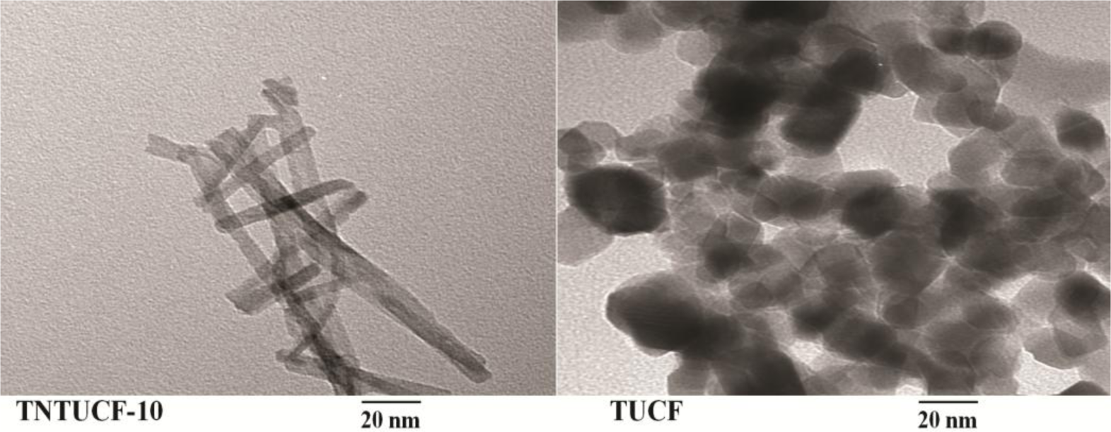
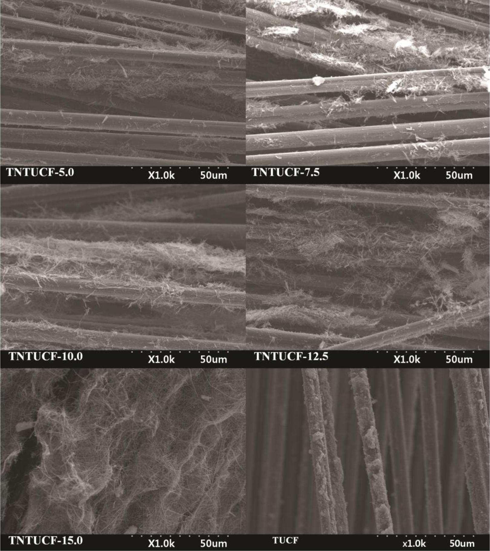
TNTUCFs with different TiO2 loadings, as well as a reference TUCF photocatalyst, were characterized by SEM, EDX, TEM, and XRD analyses. Figure 1 displays the SEM photographs of TNTUCF-5, TNTUCF-7.5, TNTUCF-10, TNTUCF-12.5, TNTUCF-15 and TUCF. The SEM images of TNTUCFs showed the TNT arrays grown on UCFs, of which the degree of cover was increased with increasing TiO2 loading, whereas SEM images of TUCF exhibited TiO2 nanoparticles coated onto UCFs. In addition, the TEM images of TNTUCF-10 revealed the nanotubular structure, whereas those for TUCF showed spherical shapes (Figure 2). Similarly, Fu et al. [19] reported that an N-TiO2 structure prepared using a solid-state reaction method with NH4Cl as the nitrogen source revealed a tubular structure in its TEM image. For the present study, the length and outer diameter of the TNTUCF-10 were ca. 20–110 nm and ca. 6–11 nm, respectively. Consequently, these results demonstrated that the hydrothermal process used in this study could be used to grow TNTs on the surface of the supporting substrate (UCF) to form TNTUCFs. In addition, Guo et al. [12] reported that TiO2 nanosheet arrays could be successfully grown on UCFs via an alternative hydrothermal process.
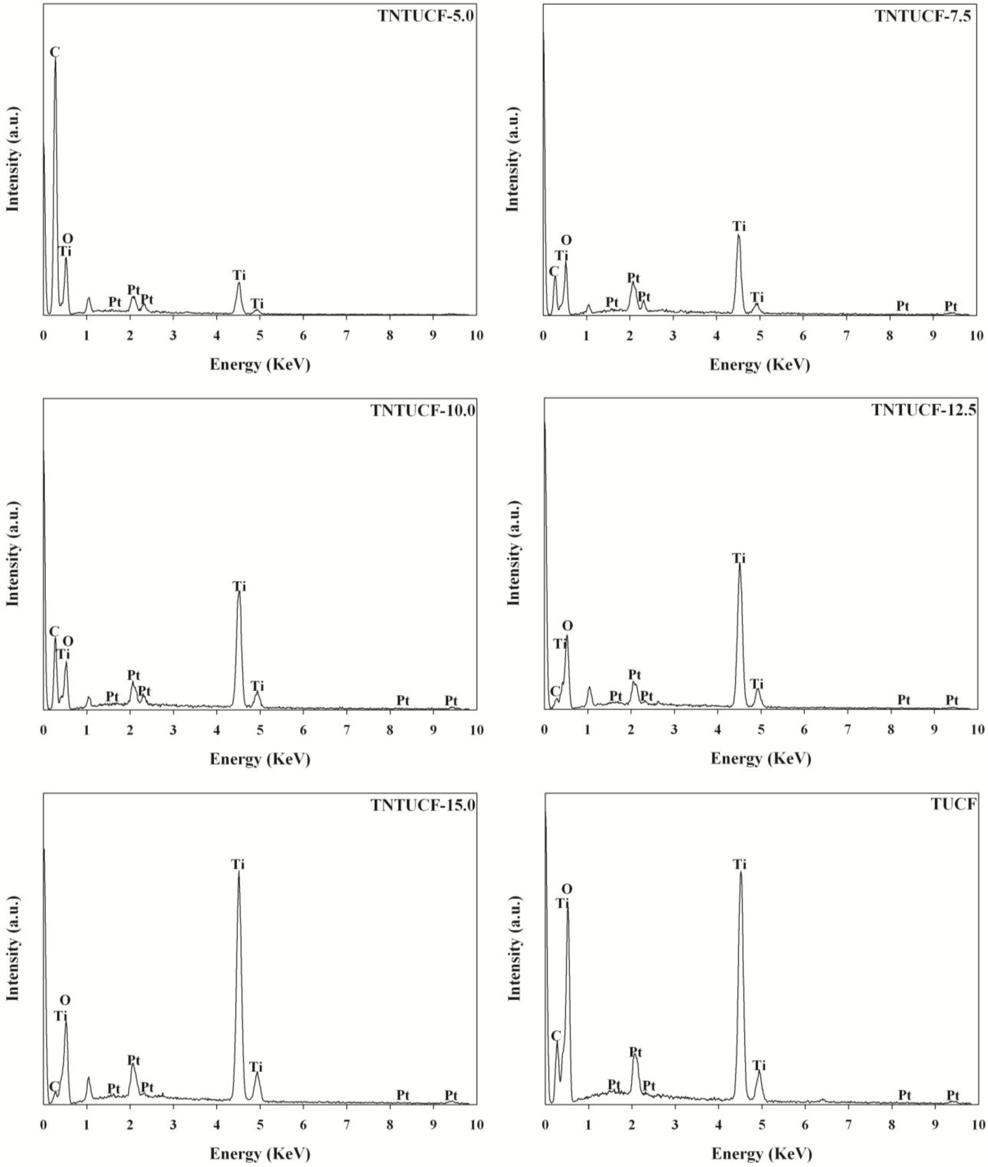
The EDX spectra of the TNTUCFs displayed peaks of C, Ti, Pt, and O atoms with different peak intensities (Figure 3). The peaks of the Ti and O atoms were assigned to TiO2, while the C atom peak was attributed to UCF. In addition, Pt atoms were considered to have originated from the Pt coating pretreatment of the TNTUCF samples prior to conducting SEM analysis. Similar to the TNTUCFs,the EDX spectra of the TUCF also revealed peaks of C, Ti, Pt, and O atoms, although their peak intensities differed.
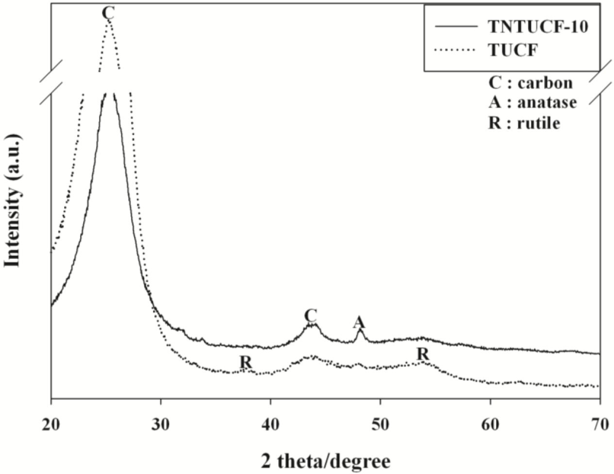
Figure 4 illustrates the XRD images of TNTUCF-10 and TUCF. Both photocatalysts showed a broad C peak at 2θ = 25.3° and a smaller C peak at 2θ = 43.3°. In addition, TNTUCF-10 revealed an anatase crystal phase with a peak at 2θ = 48.2°, while the typical anatase peak at 2θ = 25.3° was thought to be overlapped with the carbon peak of UCFs. These results were similar to those obtained by Chen et al. [11]. Accordingly, the prepared one-dimensional structured TNTs had the characteristics of TiO2 crystals, which have photocatalytic activity for the degradation of environmental pollutants. In contrast, TUCF showed rutile crystal phases with two peaks at 2θ = 37.6° and 53.9°, while the typical anatase peak at 2θ = 25.3° and rutile peak at 2θ = 27.4° were thought to be overlapped with the carbon peak of UCFs. These results were ascribed to the uses of Degussa P25 TiO2 for the preparation of TUCF, which is composed of both rutile and anatase phases. Although the UV-Vis spectra of the prepared photocatalysts were not shown in this paper because of limited space, their band gap energies estimated using their UV-Vis absorption spectra were all close to 3.1 eV.
2.2. Photocatalytic Activity of As-Prepared Photocatalysts
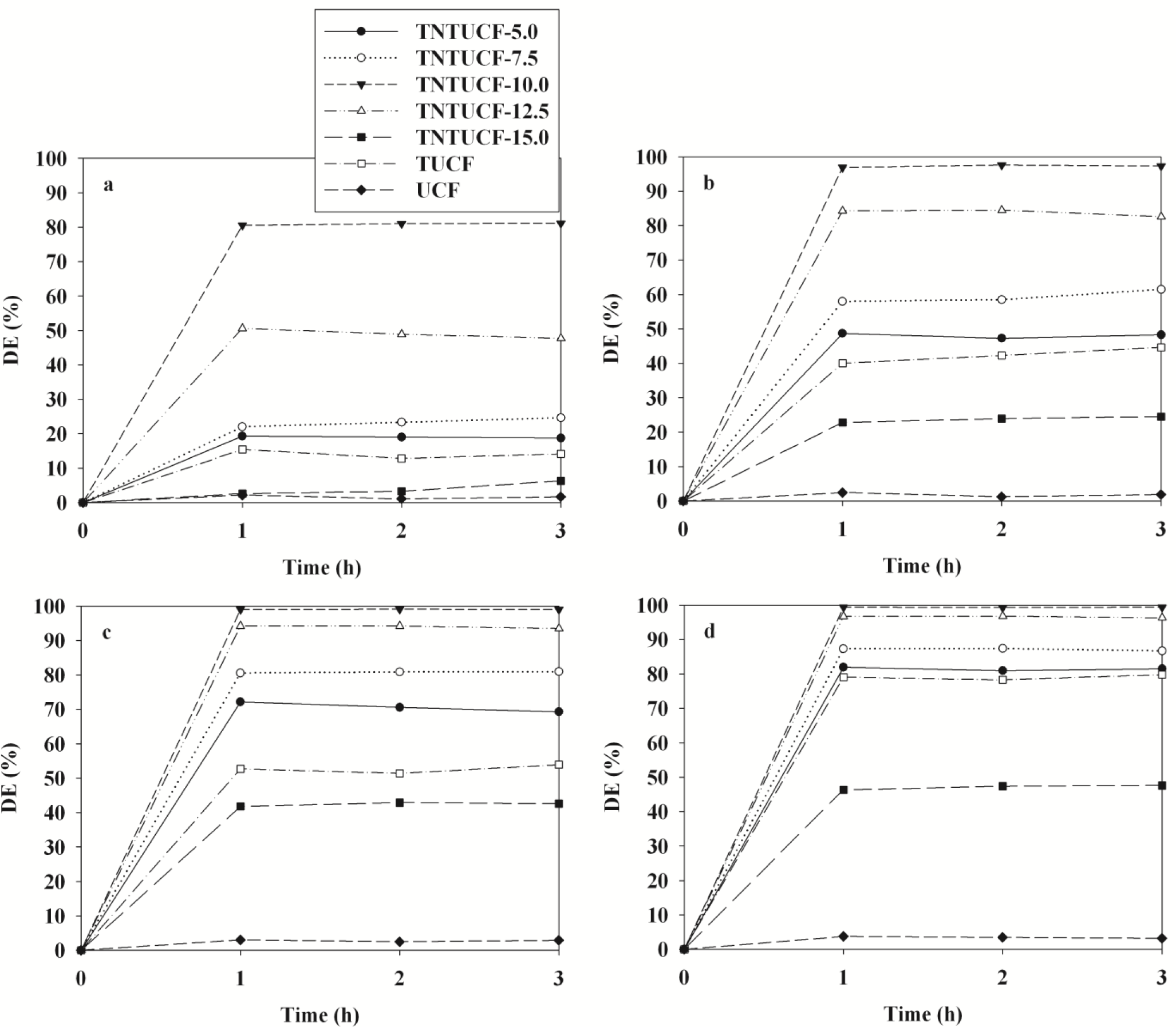
The photocatalytic activity of four TNTUCFs, TUCF, and UCF were evaluated based on their ability to decompose four target compounds (BTEX). Figure 5 shows the time-series degradation efficiencies of BTEX observed via the as-prepared photocatalysts. All BTEX degradation efficiencies determined for the TNTUCFs were higher than those of TUCF and UCF, except for those of TNTUCF-15. Specifically, the average degradation efficiencies of BTEX for the TNTUCF-10 were 81%, 97%, 99% and 99%, respectively, while those for TUCF were 14%, 42%, 52% and 79%, respectively. Additionally, the BTEX removal efficiencies determined via the TNTUCF-10 were higher than those obtained via a prototype photocatalyst (P25 TiO2), which were reported inJo et al. [10]. Specifically, the aforementioned study reported that the average degradation efficiencies of BTEX determined for P25 TiO2 under similar operational conditions were 28%, 38%, 51%, and 64%, respectively. The higher degradation efficiencies of TNTUCFs were attributed to synergistic effects between their large adsorption capacity and reduced recombination rates of photo-induced electron and hole pairs of one-dimensional nanostructured TNTs [1–3]. Moreover, the BTEX degradation efficiencies determined for the TNTUCFs increased as the TiO2 loadings increasedfrom 5% to 10%, but then decreased as the TiO2 loadings increased further from 10% to 15%. Specifically, the average degradation efficiencies of BTEX for the TNTUCF-5 were 19%, 48%, 71%, and 81%, respectively, while those for TNTUCF-15 were 4%, 24%, 42%, and 47%, respectively. These findings allowed for the optimization of TiO2 loading during TNTUCFs preparation for BTEX degradation. For high TiO2 loading conditions, TiO2 nanoparticles might block some of carbon sites, lowering adsorption capacity of prepared photocatalysts. In a similar study, Chen et al. [11] reported that TNTUCF showed a higher photocatalytic efficiency for the degradation of aqueous rhodamine B when compared with pure UCF. In addition, Guo et al. [12] showed that TiO2 nanosheets grown on carbon fibers had higher photocatalytic activities for aqueous methyl orange when compared with pure UCF. Meanwhile, a long-term study is suggested to examine the dependence of the activity of the prepared photocatalysts on application time.
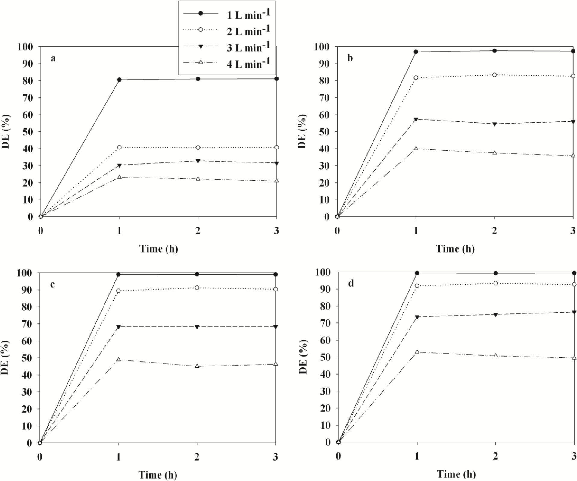
The time-series degradation efficiencies of BTEX obtained via the representative TNTUCF-10 according to air flow rates (AFRs) are shown in Figure 6. The BTEX degradation efficiencies revealed a decreasing trend with increasing AFRs. Specifically, the average degradation efficiencies of BTEX decreased from 81% to 22%, 97% to 37%, 99% to 46%, and 99% to 51%, respectively, as the AFR increased from 1 to 4 L·min−1. Similarly, Yu and Brouwers [20] reported a descending trend in NO degradation efficiencies within an AFR range of 1–5 L·min−1. These results were attributed to the mass transfer of target compounds to the surface of the catalysts and the reaction kinetics of target compounds, which are two important factors of heterogeneous photocatalytic degradation [21,22]. The mass transfer rate of gas-phase pollutants in a plug-flow reactor is strongly associated with the face velocities of air [23]. Accordingly, the degradation efficiencies of BTEX might have increased as face velocities increased, if the increased mass transfer rate was likely a crucial factor for the photocatalytic degradation kinetics of BTEX. Conversely, for the present study, the degradation efficiencies of BTEX decreased as the face velocities increased. Specifically, the face velocities for AFRs of 1, 2, 3, and 4 L·min−1 corresponded to 2.1, 4.2, 6.3, and 8.4 cm·s−1, respectively, suggesting that the degradation efficiencies of BTEX obtained from TNTUCF-10 would have been somewhat limited by reaction kinetics on the photocatalyst surface. This suggestion was supported by the finding that the residence times of the target compounds in the plug-flow reactor, which were calculated by dividing the reactor volume by the AFRs, decreased as the AFR increased. Specifically, the residence times for the AFRs of 1, 2, 3 and 4 L·min−1 were 16.4, 12.3, 8.2 and 4.1 s, respectively. Consequently, the low degradation efficiencies of BTEX under high AFR conditions were likely due to low reaction rates on the catalyst surface because of insufficient reaction times in the plug-flow reactor.
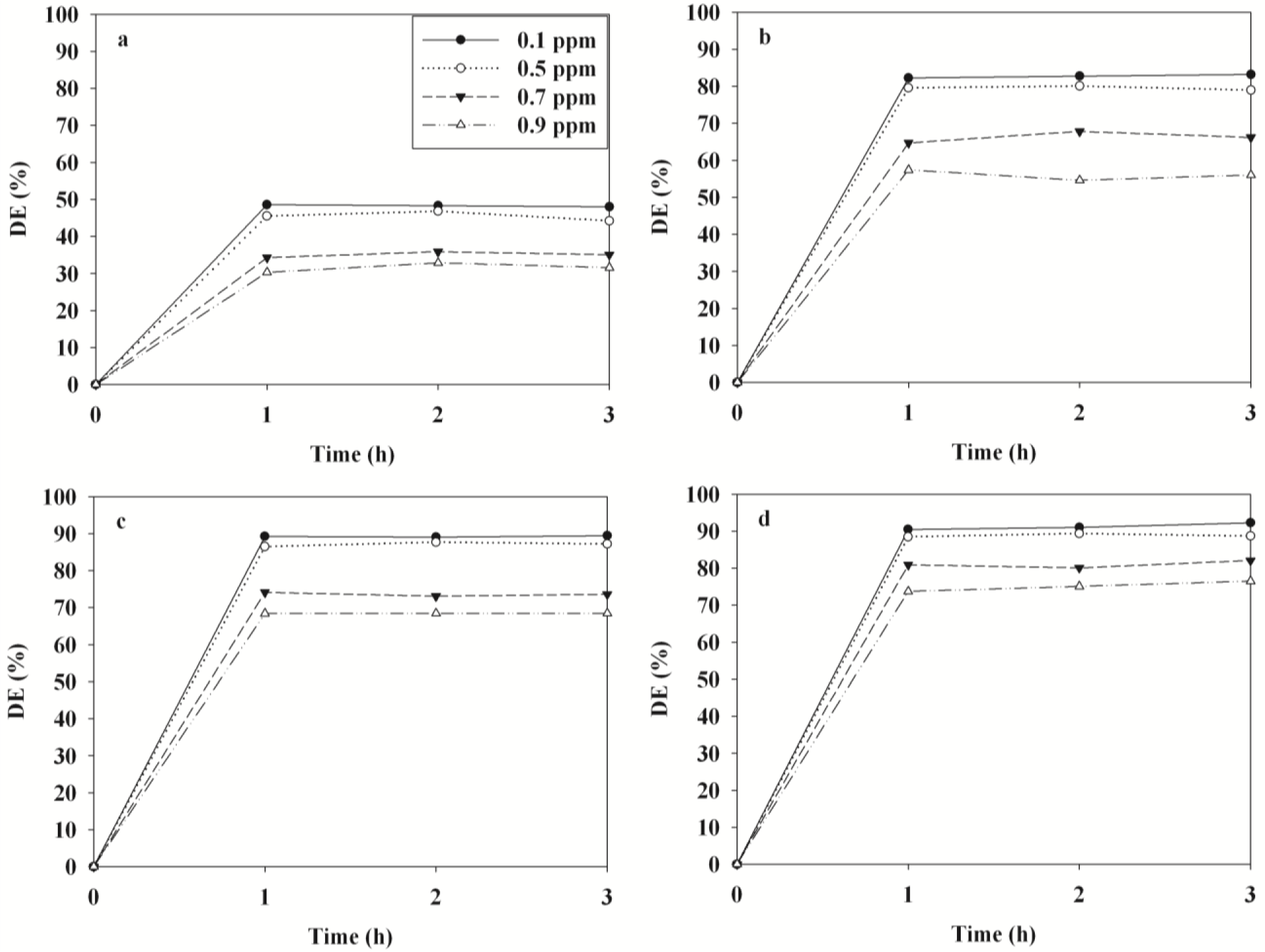
Figure 7 illustrates the time-series degradation efficiencies of BTEX determined via TNTUCF-10 according to input concentrations (ICs) within a range of typical indoor air concentrations. For the target compounds, the degradation efficiencies decreased as ICs increased. Specifically, at the lowest IC of 0.1 ppm the average degradation efficiencies of BTEX were 48%, 83%, 89% and 91%, respectively, whereas those for the highest IC of 0.9 ppm were 32%, 56%, 68% and 75%, respectively. Similarly, Devahasdin et al. [24] reported that the NO degradation efficiency determined using UV-activated TiO2 decreased from 70% to 15% when IC increased from 5 to 60 ppm. Yu and Brouwers [20] also found that the degradation efficiency of NO determined using visible light-activated carbon-impregnated TiO2 decreased from 61% to 16% when IC increased from 0.1 to 0.9 ppm. Because chemical adsorption onto photocatalyst surfaces is known as a primary factor influencing the degradation efficiency of chemicals [22], the increasing pattern in degradation efficiencies with IC increases was ascribed to adsorption competition of BTEX molecules on the catalyst surface. Specifically, a small amount of the active adsorption sites on the surface of the TNTUCF-10 under low IC conditions would have been available for BTEX adsorption before the surface reaction was initiated.
3. Experimental Section
3.1. Synthesis and Characterization of TUCF and TNTUCFs
A TUCF was synthesized using a simple coating process, while TNTUCFs with different TiO2 loadings were prepared by hydrothermally treating the prepared TUCF. CF sheets (Hyundai Fiber Co., Hanam, Korea) were first washed with NaOH solution (1 M, Sigma-Adrich, St. Louis, MO, USA) and then with distilled water, after which they were dried in an oven at 110 °C. The cleaned CFs were immersed into tetrabutyl titanate (TBT, Sigma-Aldrich, St. Louis, MO, USA)-hexane (Sigma-Aldrich, St. Louis, MO, USA) solution (10 vol% TBT) for 10 min and were then exposed to water-saturated air for the hydrolysis of TBT. These immersion and hydrolysis processes were repeated five times in order to obtain high TiO2 loaded CFs. The coated CF was calcined in an oven at 400 °C for 6 h to obtain TUCF. In addition, CF sheets were immersed in TBT-hexane solutions (5%, 7.5%, 10%, 12.5%, or 15%) to prepare TNTUCFs with different TiO2 loadings (named as TNTUCF-5, TNTUCF-7.5, TNTUCF-10, TNTUCF-12.5, or TNTUCF-15, respectively). To hydrothermally treat the coated CFs, they were rolled up and immersed into NaOH solution (10 M) in a stainless steel autoclave (170 mL) with Teflon-lined inner-walls, after which they were heated at 160 °C for 48 h. The autoclave was then cooled down to room temperature, and the hydrothermally treated samples were washed with acetic acid (0.1 M, Sigma-Aldrich, St. Louis, MO, USA) and distilled water in turn, after which they were calcined in an oven at 400 °C for 6 h to obtain final products, as white powders. The characteristics of the prepared TNTUCFs and TUCF were examined using scanning electron microscopy (FE-SEM, Hitachi S-4300, Tokyo, Japan), energy-dispersive X-ray (EDX, Hitachi EDX-350, Tokyo, Japan), transmission electron microscopy (TEM, Hitachi H-7600, Tokyo, Japan), and X-ray diffraction (XRD, Rigaku D/max-2500 diffractometer, Rigaku, Tokyo, Japan) spectroscopy. In addition, for the calculation of band gaps of the prepared photocatalysts, UV-Vis absorption spectra were obtained for the dry pressed disk samples using a Varian CARY 5G spectrophotometer (Vrian Inc., Cary, NC, USA) in the wavelength range between 200 and 800 nm at a scanning rate of 120 nm/min.
3.2. Photocatalysis of BTEX via TNTUCFs and TUCF
The photocatalytic activity of the TNTUCFs, TUCF, and UCF for the degradation of aromatic VOCs were examined using a continuous-flow Pyrex tubing reactor (4.0 cm inside diameter (i.d.) and26.5 cm length), the inner wall of which was covered with each of the prepared photocatalysts. A cylindrical UV-light source (8-W fluorescent black light lamp, F8T5BL, Youngwha Lamp Co., Seoul, Korea) was inserted inside the Pyrex reactor, serving as the inside surface boundary layer of the reactor. The high-purity dried air supplied by the air cylinder was further cleaned by passing through an activated carbon filter. Humidified air was generated by passing the cleaned air through a humidification device immersed in a water bath. Standard gases were produced by mixing the humidified air with the target chemicals injected into a heated buffering Pyrex bulb via anauto-controlled syringe pump (Model Legato 100, KdScientific Inc., Holliston, MA, USA). The produced standard gases were allowed to flow into another buffering Pyrex bulb to decrease the fluctuation of input concentration fluctuation prior to being fed into the photocatalytic reactor.
The photocatalytic activity tests of the prepared photocatalysts were conducted under different operational conditions by varying air flow rates (AFRs) and input concentrations (ICs). The AFRs were adjusted to 1.0, 2.0, 3.0, or 4.0 L·min−1, while ICs were adjusted to 0.1, 0.5, 0.7, or 0.9 ppm.For each parameter test, the other parameters were fixed to their representative values: AFR,1.0 L·min−1; and IC, 0.9 ppm. The relative humidity (RH) was fixed 45%, which is within the range of comfort (40%–60%) recommended by the American Society of Heating, Refrigerating and Air Conditioning Engineers. The hydraulic diameter (HD, defined as the inner diameter of the Pyrex tubing reactor minus the outside diameter of the light source) of the Pyrex reactor was 1.2 mm. The light intensity supplied by the light source was 0.4 mW·cm−2 at a distance from the light source equal to half the HD of the photocatalytic reactor. Each test was repeated three times in order to obtain more reliable results.
Measurements of gaseous chemicals were conducted both upstream and downstream of the Pyrex tubing reactor. Gas samples were collected by drawing air through a stainless steel tube (1/4 in. i.d. and 10 cm length) containing Tenax-TA adsorbent. The gaseous species collected on the Tenax-TA trap were analyzed by combining a thermal desorbing device (ATD 500, Perkin Elmer Co., Shelton, CT, USA) to a gas chromatograph (GC, Perkin Elmer Clarus 680, Shelton, CT, USA)/mass spectrometer (MS, Perkin Elmer Clarus SQ8 T, Shelton, CT, USA) equipped with a capillary column (DB-1, Agilent Co., Santa Clara, CA, USA). The trap was thermally desorbed at 250 °C for 10 min, and the gaseous species were cryofocussed at −30 °C using an internal cryo trap, after which they were rapidly heated to 250 °C and subsequently flushed to transfer the target compounds to the GC/MS system. The initial oven temperature was set to 40 °C for 5 min, and was then ramped to 230 °C at5 °C min−1 for 7 min. The gaseous species were identified based on their reaction times and mass spectra (Wiley 275 software library), while their quantification was carried out using calibration equations based on five different concentrations. The quality control program for gas measurements included blank and spiked sample traps. On each day, a blank sample was analyzed in order to examine the trap for contamination. A spiked sample was analyzed daily to validate the quantitative response of the analytical system. The method detection limits for BTEX ranged from 0.005 to0.008 ppm, depending on the chemical species.
4. Conclusions
In this study, TNTUCFs with different TiO2 loadings were prepared using a coating-hydrothermal process and their photocatalytic activities were investigated for the decomposition of sub-ppm levels of aromatic pollutants using a plug-flow photocatalytic reactor. Spectral results of the prepared photocatalysts were closely associated with the characteristics of one-dimensional nanostructured TNTs for TNTUCFs and spherical shapes for TUCF. TNTUCFs exhibited superior photocatalytic degradation of BTEX compared to that of TUCF. Moreover, the photocatalytic activities obtained from TNTUCFs suggested that the degradation efficiencies of BTEX varied with changes in TiO2 loading, allowing for the optimization of TiO2 loading. Another important finding was that ICs and AFRs could be important parameters for the treatment of sub-ppm level vapors, which should be considered for the optimum operation of TNTUCFs.
Acknowledgments
This work was supported by the National Research Foundation of Korea (NRF) grant fundedby the Korean government (MEST) (2011-0027916) and the Korean government (MSIP) through GCRC-SOP (No. 2011-0030013).
Author Contributions
Wan-Kuen Jo established the research protocol and analyzed the experimental data. Joon Yeob lee performed experimental works, and Ho-Hwan Chun assisted in data analysis.
Conflicts of Interest
The authors declare no conflict of interest.
References
- Nakata, K.; Fujishima, A. TiO2 photocatalysis: Design and applications. J. Photochem. Photobiol. C 2012, 13, 169–189. [Google Scholar]
- Toledo-Antonio, J.A.; Capula, S.; Cortés-Jácome, M.A.; Angeles-Chávez, C.; López-Salinas, E.; Ferrat, G.; Navarrete, J.; Escobar, J. Low-temperature FTIR study of CO adsorption on titania nanotubes. J. Phys. Chem. C 2007, 111, 10799–10805. [Google Scholar]
- Yang, H.Y.; Yu, S.F.; Lau, S.P.; Zhang, X.; Sun, D.D.; Jun, G. Direct growth of ZnO nanocrystals onto the surface of porous TiO2 nanotube arrays for highly efficient and recyclable photocatalysts. Small 2009, 5, 2260–2264. [Google Scholar]
- Tachikawa, T.; Tojo, S.; Fujitsuka, M.; Sekino, T.; Majima, T. Photoinduced charge separation in titania nanotubes. J. Phys. Chem. B 2006, 110, 14055–14059. [Google Scholar]
- Toledo-Antonio, J.A.; Cortes-Jacome, M.A.; Orozco-Cerros, S.L.; Montiel-Palacios, E.; Suarez-Parra, R.; Angeles-Chavez, C.; Navarete, J.; López-Salinas, E. Assessing optimal photoactivity on titania nanotubes using different annealing temperatures. Appl. Catal. B 2010, 100, 47–54. [Google Scholar]
- Górska, P.; Zaleska, A.; Kowalska, E.; Klimczuk, T.; Sobczak, J.W.; Skwarek, E.; Janusz, W.; Hupka, J. TiO2 photoactivity in vis and UV light: The influence of annealing temperature and surface properties. Appl. Catal. B 2008, 84, 440–447. [Google Scholar]
- Matos, J.; García-López, E.; Palmisano, L.; García, A.; Marci, G. Influence of activated carbon in TiO2 and ZnO mediated photo-assisted degradation of 2-propanol in gas-solid regime. Appl. Catal. B 2010, 99, 170–180. [Google Scholar]
- Jo, W.K.; Shin, S.H.; Hwang, E.S. Removal of dimethyl sulfide utilizing activated carbon fiber-supported photocatalyst in continuous-flow system. J. Hazard. Mater 2011, 191, 234–239. [Google Scholar]
- Verbruggen, S.W.; Ribbens, S.; Tytgat, T.; Hauchecorne, B.; Smits, M.; Meynen, V.; Cool, P.; Martens, J.A.; Lenaerts, S. The benefit of glass bead supports for efficient gas phase photocatalysis: Case study of a commercial and a synthesised photocatalyst. Chem. Eng. J 2011, 174, 318–325. [Google Scholar]
- Chun, H.-H.; Lee, J.Y.; Jo, W.-K. Photocatalysis of low-concentration gaseous organic pollutants over electrospun iron-doped titanium dioxide nanofibers. Solid State Sci 2013, 25, 103–109. [Google Scholar]
- Chen, P.; Gu, L.; Xue, X.; Li, M.; Cao, X. Engineering the growth of TiO2 nanotube arrays on flexible carbon fibre sheets. Chem. Commun 2010, 46, 5906–5908. [Google Scholar]
- Guo, W.; Zhang, F.; Lin, C.; Wang, Z.L. Direct growth of TiO2 nanosheet arrays on carbon fibers for highly efficient photocatalytic degradation of methyl orange. Adv. Mater 2012, 24, 4761–4764. [Google Scholar]
- Leary, R.; Westwood, A. Carbonaceous nanomaterials for the enhancement of TiO2 photocatalysis. Carbon 2011, 49, 741–772. [Google Scholar]
- Bozzi, A.; Yuranova, T.; Guasaquillo, I.; Laub, D.; Kiwi, J. Self-cleaning of modified cotton textiles by TiO2 at low temperatures under daylight irradiation. J. Photochem. Photobiol. A 2005, 174, 156–164. [Google Scholar]
- Ochiai, T.; Fujishima, A. Photoelectrochemical properties of TiO2 photocatalyst and its applications for environmental purification. J. Photochem. Photobiol. C 2012, 13, 247–262. [Google Scholar]
- Ohura, T.; Amagai, T.; Shen, X.; Li, S.; Zhang, P.; Zhu, L. Comparative study on indoor air quality in Japan and China: Characteristics of residential indoor and outdoor VOCs. Atmos. Environ 2009, 43, 6352–6359. [Google Scholar]
- Rumchev, K.; Brown, H.; Spickett, J. Volatile organic compounds: Do they present a risk to our health? Rev. Environ. Health 2007, 22, 39–55. [Google Scholar]
- World Health Organization (WHO), Air quality guidelines for Europe; Regional Office for Europe: Copenhagen, 2000; Available online: http://www.euro.who.int/_data./pdf_file/0005/74732/E71922.pdf (accessed on 11 December 2012).
- Fu, J.; Tian, Y.; Chang, B.; Xi, F.; Dong, X. Facile fabrication of N-doped TiO2 nanocatalyst with superior performance under visible light irradiation. J. Solid State Chem 2013, 199, 280–286. [Google Scholar]
- Yu, Q.L.; Brouwers, H.J.H. Indoor air purification using heterogeneous photocatalytic oxidation. Part I: Experimental study. Appl. Catal. B 2009, 92, 454–461. [Google Scholar]
- Demeestere, K.; Dewulf, J.; van Langenhove, H. Heterogeneous photocatalysis as an advanced oxidation process for the abatement of chlorinated, monocyclic aromatic and sulfurous volatile organic compounds in air: State of the art. Crit. Rev. Environ. Sci. Technol 2007, 37, 489–538. [Google Scholar]
- Fujishima, A.; Zhang, X.; Tryk, S.A. TiO2 photocatalysis and related surface phenomena. Surf. Sci. Rep 2008, 63, 515–582. [Google Scholar]
- Boulinguiez, B.; Bouzaza, A.; Merabet, S.; Wolbert, D. Photocatalytic degradation of ammonia and butyric acid in plug-flow reactor: Degradation kinetic modeling with contribution of mass transfer. J. Photochem. Photobiol 2008, 200, 254–261. [Google Scholar]
- Devahasdin, S.; Fan, C.; Li, K., Jr.; Chen, D.H. TiO2 photocatalytic oxidation of nitric oxide: Transient behavior and reaction kinetics. J. Photochem. Photobiol. A 2003, 156, 161–170. [Google Scholar]


© 2014 by the authors; licensee MDPI, Basel, Switzerland This article is an open access article distributed under the terms and conditions of the Creative Commons Attribution license (http://creativecommons.org/licenses/by/3.0/).
Share and Cite
Jo, W.-K.; Lee, J.Y.; Chun, H.-H. Titania Nanotubes Grown on Carbon Fibers for Photocatalytic Decomposition of Gas-Phase Aromatic Pollutants. Materials 2014, 7, 1801-1813. https://doi.org/10.3390/ma7031801
Jo W-K, Lee JY, Chun H-H. Titania Nanotubes Grown on Carbon Fibers for Photocatalytic Decomposition of Gas-Phase Aromatic Pollutants. Materials. 2014; 7(3):1801-1813. https://doi.org/10.3390/ma7031801
Chicago/Turabian StyleJo, Wan-Kuen, Joon Yeob Lee, and Ho-Hwan Chun. 2014. "Titania Nanotubes Grown on Carbon Fibers for Photocatalytic Decomposition of Gas-Phase Aromatic Pollutants" Materials 7, no. 3: 1801-1813. https://doi.org/10.3390/ma7031801