Nanoscale Topographical Characterization of Orbital Implant Materials


Abstract
:1. Introduction
2. Materials and Methods
2.1. Ocular Implant Materials
2.2. Characterization
2.3. Statistical Analysis
3. Results and Discussion
4. Conclusions
Author Contributions
Conflicts of Interest
References
- Feller, L.; Jadwat, Y.; Khammissa, R.A.G.; Meyerov, R.; Schechter, I.; Lemmer, J. Cellular responses evoked by different surface characteristics of intraosseous titanium implants. Biomed. Res. Int. 2015, 2015, 1–8. [Google Scholar] [CrossRef] [PubMed]
- Wennerberg, A.; Albrektsson, T. Effects of titanium surface topography on bone integration: A systematic review. Clin. Oral Implant. Res. 2009, 20, 172–184. [Google Scholar] [CrossRef] [PubMed]
- Ross, A.M.; Jiang, Z.; Bastmeyer, M.; Lahann, J. Physical aspects of cell culture substrates: Topography, roughness, and elasticity. Small 2012, 8, 336–355. [Google Scholar] [CrossRef] [PubMed] [Green Version]
- Salerno, M.; Caneva-Soumetz, F.; Pastorino, L.; Patra, N.; Diaspro, A.; Ruggiero, C. Adhesion and proliferation of osteoblast-like cells on anodic porous alumina substrates with different morphology. IEEE Trans. Nanobiosci. 2013, 12, 106–111. [Google Scholar] [CrossRef] [PubMed]
- Schwartz, Z.; Boyan, B.D. Underlying mechanisms at the bone–biomaterial interface. J. Cell. Biochem. 1994, 56, 340–347. [Google Scholar] [CrossRef] [PubMed]
- Guehennec, L. Surface treatments of titanium dental implants for rapid osseointegration. Dent. Mater. 2007, 3, 844–854. [Google Scholar] [CrossRef] [PubMed]
- Qu, Z.; Rausch-Fan, X.; Wieland, M.; Matejka, M.; Schedle, A. The initial attachment and subsequent behavior regulation of osteoblasts by dental implant surface modification. J. Biomed. Mater. Res. Part A 2006, 82, 658–668. [Google Scholar] [CrossRef] [PubMed]
- Ventre, M.; Natale, C.F.; Rianna, C.; Netti, P.A. Topographic cell instructive patterns to control cell adhesion, polarization and migration. J. R. Soc. Intefrace 2014. [Google Scholar] [CrossRef] [PubMed]
- Courtney, J.M.; Lamba, N.M.K.; Sundaram, S.; Forbes, C.D. Biomaterials for blood-contacting applications. Biomaterials 1994, 15, 737–744. [Google Scholar] [CrossRef]
- Baino, F.; Potestio, I. Orbital implants: State-of-the-art review with emphasis on biomaterials and recent advances. Mater. Sci. Eng. C Mater. Biol. Appl. 2016, 69, 1410–1428. [Google Scholar] [CrossRef] [PubMed]
- Moshfeghi, D.M.; Moshfeghi, A.A.; Finger, P.T. Enucleation. Surv. Ophthalmol. 2000, 44, 277–301. [Google Scholar] [CrossRef]
- Patil, S.B.; Meshramkar, R.; Naveen, B.H.; Patil, N.P. Ocular prosthesis: A brief review and fabrication of an ocular prosthesis for a geriatric patient. Gerodontology 2008, 25, 57–62. [Google Scholar] [CrossRef] [PubMed]
- Chalasani, R.; Poole-Warren, L.; Conway, R.M.; Ben-Nissan, B. Porous Orbital Implants in Enucleation: A Systematic Review. Surv. Ophthalmol. 2007, 52, 145–155. [Google Scholar] [CrossRef] [PubMed] [Green Version]
- Nunery, W.R.; Heinz, G.W.; Bonnin, J.M.; Martin, R.T.; Cepela, M.A. Exposure rate of hydroxyapatite spheres in the anophthalmic socket: Histopathologic correlation and comparison with silicone sphere implants. Ophthalmic Plast. Reconstr. Surg. 1993, 9, 96–104. [Google Scholar] [CrossRef]
- Dutton, J.J. Coralline Hydroxyapatite as an Ocular Implant. Ophthalmology 1991, 98, 370–377. [Google Scholar] [CrossRef]
- Gayre, G.S.; Lipham, W.; Dutton, J.J. A comparison of rates of fibrovascular ingrowth in wrapped versus unwrapped hydroxyapatite spheres in a rabbit model. Ophthalmic Plast. Reconstr. Surg. 2002, 18, 275–280. [Google Scholar] [CrossRef]
- Baino, F. Porous glass-ceramic orbital implants: A feasibility study. Mater. Lett. 2018, 212, 12–15. [Google Scholar] [CrossRef]
- Baino, F.; di Confiengo, G.G.; Faga, M.G. Fabrication and morphological characterization of glass-ceramic orbital implants. Int. J. Appl. Ceram. Technol. 2017, 1–8. [Google Scholar] [CrossRef]
- Lombardo, M.; Carbone, G.; Lombardo, G.; De Santo, M.P.; Barberi, R. Analysis of intraocular lens surface adhesiveness by atomic force microscopy. J. Cataract Refract. Surg. 2009, 35, 1266–1272. [Google Scholar] [CrossRef] [PubMed]
- Choi, S.; Lee, S.J.; Shin, J.-H.; Cheong, Y.; Lee, H.-J.; Paek, J.H.; Kim, J.S.; Jin, K.-H.; Park, H.-K. Ultrastructural investigation of intact orbital implant surfaces using atomic force microscopy. Scanning 2011, 33, 211–221. [Google Scholar] [CrossRef] [PubMed]
- ISO 25178-2:2012. Geometrical Product Specifications (GPS)—SurfaceTexture: Areal—Part 2: Terms, Definitions and Surface Texture Parameters. Available online: https://www.iso.org/obp/ui/#iso:std:iso:25178:-2:ed-1:v1:en (accessed on 16 March 2018).
- Toccafondi, C.; Dante, S.; Reverberi, A.P.; Salerno, M. Biomedical Applications of Anodic Porous Alumina. Curr. Nanosci. 2015, 11, 572–580. [Google Scholar] [CrossRef]
- Toccafondi, C.; Thorat, S.; La Rocca, R.; Scarpellini, A.; Salerno, M.; Dante, S.; Das, G. Multifunctional substrates of thin porous alumina for cell biosensors. J. Mater. Sci. Mater. Med. 2014, 25, 2411–2420. [Google Scholar] [CrossRef] [PubMed]
- Zhu, Y.Y.; Ding, G.Q.; Ding, J.N.; Yuan, N.Y. AFM, SEM and TEM studies on porous anodic alumina. Nanoscale Res. Lett. 2010, 5, 725–734. [Google Scholar] [CrossRef] [PubMed]
- Alwitry, A.; West, S.; King, J.; Foss, A.J.; Abercrombie, L.C. Long-term follow-up of porous polyethylene spherical implants after enucleation and evisceration. Ophthalmic Plast. Reconstr. Surg. 2007, 23, 11–15. [Google Scholar] [CrossRef] [PubMed]
- Mahoney, N.R.; Grant, M.P.; Iliff, N.T.; Merbs, S.L. Exposure rate of smooth surface tunnel porous polyethylene implants after enucleation. Ophthalmic Plast. Reconstr. Surg. 2014, 30, 492–498. [Google Scholar] [CrossRef] [PubMed]
- Timoney, P.J.; Clark, J.D.; Frederick, P.A.; Krakauer, M.; Compton, C.; Horbinski, C.; Sokol, J.; Nunery, W.R. Foreign Body Granuloma Following Orbital Reconstruction with Porous Polyethylene. Ophthalmic Plast. Reconstr. Surg. 2016, 32, e137–e138. [Google Scholar] [CrossRef] [PubMed]
- Jordan, D.R.; Brownstein, S.; Dorey, M.; Yuen, V.H.; Gilberg, S. Fibrovascularization of porous polyethylene (Medpor) orbital implant in a rabbit model. Ophthalmic Plast. Reconstr. Surg. 2004, 20, 136–143. [Google Scholar] [CrossRef]
- Xu, L.-C.; Siedlecki, C.A. Effects of surface wettability and contact time on protein adhesion to biomaterial surfaces. Biomaterials 2007, 28, 3273–3283. [Google Scholar] [CrossRef] [PubMed]
- Salerno, M.; Giacomelli, L.; Derchi, G.; Patra, N.; Diaspro, A. Atomic force microscopy in vitro study of surface roughness and fractal character of a dental restoration composite after air-polishing. Biomed. Eng. Online 2010, 9, 59. [Google Scholar] [CrossRef] [PubMed]
- Salerno, M.; Loria, P.; Matarazzo, G.; Tomè, F.; Diaspro, A.; Eggenhöffner, R. Surface Morphology and Tooth Adhesion of a Novel Nanostructured Dental Restorative Composite. Materials 2016, 9, 203–210. [Google Scholar] [CrossRef] [PubMed]
- Derchi, G.; Vano, M.; Barone, A.; Covani, U.; Diaspro, A.; Salerno, M. Bacterial adhesion on direct and indirect dental restorative composite resins: An in vitro study on a natural biofilm. J. Prosthet. Dent. 2017, 117, 669–676. [Google Scholar] [CrossRef] [PubMed]
- Ţəlu, Ş.; Patra, N.; Salerno, M. Micromorphological characterization of polymer-oxide nanocomposite thin films by atomic force microscopy and fractal geometry analysis. Prog. Org. Coat. 2015, 89, 50–56. [Google Scholar] [CrossRef]
- Brandão, S.M.; Schellini, S.A.; Moraes, A.D.; Padovani, C.R.; Pellizzon, C.H.; Peitl, O.; Zanotto, E.D. Biocompatibility analysis of Bioglass® 45S5 and Biosilicate® implants in the rabbit eviscerated socket. Orbit 2012, 31, 143–149. [Google Scholar] [CrossRef] [PubMed]
- Baino, F. How can bioactive glasses be useful in ocular surgery? J. Biomed. Mater. Res. Part A 2015, 103, 1259–1275. [Google Scholar] [CrossRef] [PubMed]
- Baino, F.; Novajra, G.; Miguez-Pacheco, V.; Boccaccini, A.R.; Vitale-Brovarone, C. Bioactive glasses: Special applications outside the skeletal system. J. Non-Cryst. Solids 2016, 432, 15–30. [Google Scholar] [CrossRef]
- Crovace, M.C.; Souza, M.T.; Chinaglia, C.R.; Peitl, O.; Zanotto, E.D. Biosilicate®—A multipurpose, highly bioactive glass-ceramic. In vitro, in vivo and clinical trials. J. Non-Cryst. Solids 2016, 432, 90–110. [Google Scholar] [CrossRef]
- Chang, E.W.; Monolidis, S. Orbital floor fracture management. Facial Plast. Surg. 2005, 21, 207–213. [Google Scholar] [CrossRef] [PubMed]
- Baino, F.; Perero, S.; Ferraris, S.; Miola, M.; Balagna, C.; Verné, E.; Vitale-Brovarone, C.; Coggiola, A.; Dolcino, D.; Ferraris, M. Biomaterials for orbital implants and ocular prostheses: Overview and future prospects. Acta Biomater. 2014, 10, 1064–1087. [Google Scholar] [CrossRef] [PubMed]
- Marano, R.; Tincani, A.J. Is there an ideal implant for orbital reconstructions? Prospective 64-case study. J. Cranio-Maxillo-Facial Surg. 2016, 44, 1682–1688. [Google Scholar] [CrossRef] [PubMed]
- Vitale-Brovarone, C.; Baino, F.; Verné, E. High strength bioactive glass-ceramic scaffolds for bone regeneration. J. Mater. Sci. Mater. Med. 2009, 20, 643–653. [Google Scholar] [CrossRef] [PubMed]
- Muzio, G.; Martinasso, G.; Baino, F.; Frairia, R.; Vitale-Brovarone, C.; Canuto, R.A. Key role of the expression of bone morphogenetic proteins in increasing the osteogenic activity of osteoblast-like cells exposed to shock waves and seeded on bioactive glass-ceramic scaffolds for bone tissue engineering. J. Biomater. Appl. 2014, 29, 728–736. [Google Scholar] [CrossRef] [PubMed]
- Mawn, L.A.; Jordan, D.R.; Gilberg, S. Proliferation of human fibroblasts in vitro after exposure to orbital implants. Can. J. Ophthalmol. 2001, 36, 245–251. [Google Scholar] [CrossRef]


| Implant Material | Specimen Shape And Size | Crystalline Phases | Total Porosity (vol %) | Mean Macropore Size (µm) |
|---|---|---|---|---|
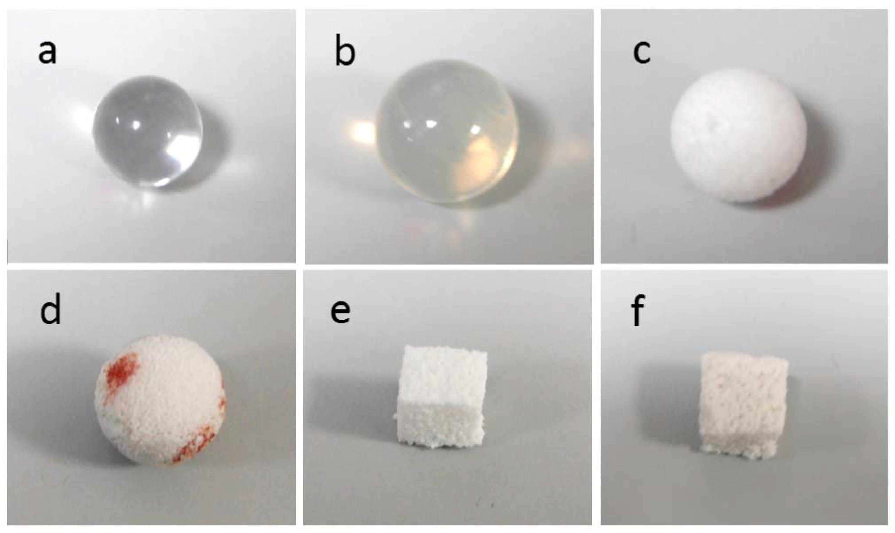
| PMMA | ball, ~12.6 mm diameter | none | 0 | - |
| Silicone | ball, ~15.9 mm diameter | none | 0 | - |
| PE | ball, ~14.9 mm diameter | none | 50 | 350 |
| Alumina | ball, ~13.9 mm diameter | Al2O3 | >75 | 500 |
| GCA | cuboid, ~1 cm side | CaSiO3 (wollastonite) | ~53 | 230 |
| GCB | cuboid, ~1 cm side | Na2Ca2Si3O9 (combeite), Na2Ca4(PO4)2SiO4 (silicorhenanite), Ca2Mg(Si2O7) (akermanite) | ~60 | 520 |
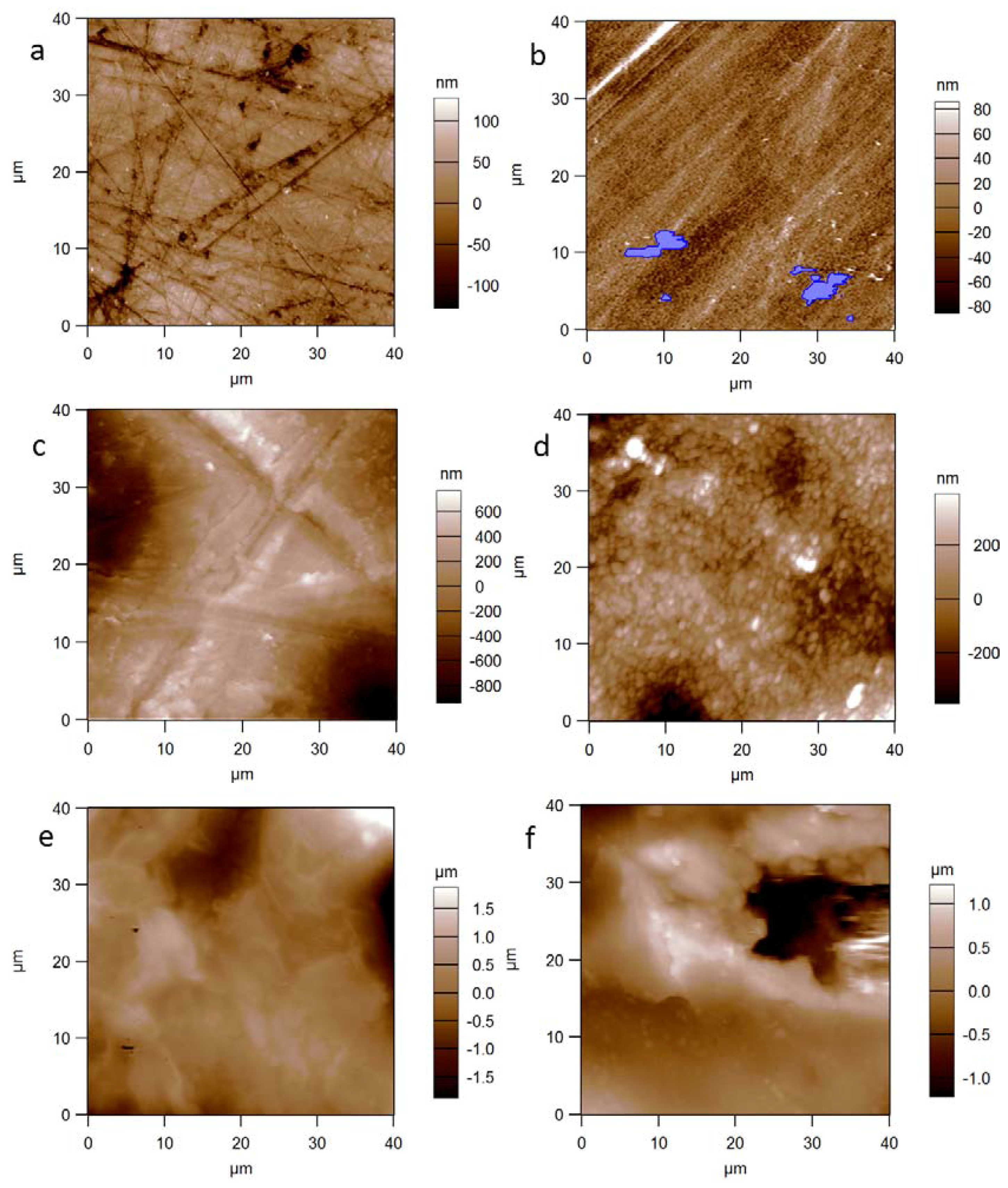
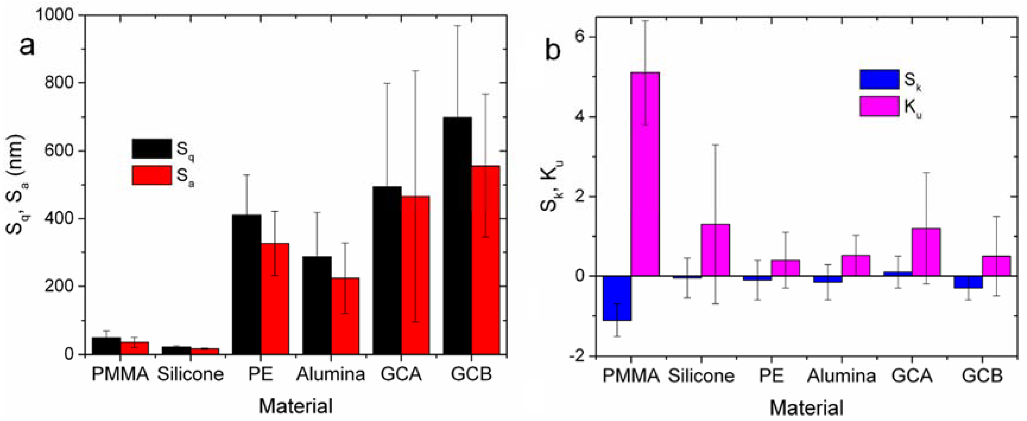
| Material | Sq (nm) | Sa (nm) | Sk | Ku |
|---|---|---|---|---|
| PMMA | 49 ± 21 | 36 ± 15 | −1.1 ± 0.4 | 5.1 ± 1.3 |
| Silicone | 22 ± 4 | 17 ± 2 | 0.1 ± 0.5 | 1.3 ± 2.0 |
| PE | 411 ± 118 | 327 ± 95 | −0.2 ± 1.0 | 0.4 ± 0.7 |
| Alumina | 287 ± 131 | 224 ± 104 | −0.2 ± 0.4 | 0.5 ± 0.5 |
| GCA | 494 ± 304 | 466 ± 370 | 0.1 ± 0.4 | 1.2 ± 1.4 |
| GCB | 699 ± 270 | 556 ± 210 | −0.3 ± 0.3 | 0.5 ± 1.0 |
© 2018 by the authors. Licensee MDPI, Basel, Switzerland. This article is an open access article distributed under the terms and conditions of the Creative Commons Attribution (CC BY) license (http://creativecommons.org/licenses/by/4.0/).
Share and Cite
Salerno, M.; Reverberi, A.P.; Baino, F. Nanoscale Topographical Characterization of Orbital Implant Materials. Materials 2018, 11, 660. https://doi.org/10.3390/ma11050660
Salerno M, Reverberi AP, Baino F. Nanoscale Topographical Characterization of Orbital Implant Materials. Materials. 2018; 11(5):660. https://doi.org/10.3390/ma11050660
Chicago/Turabian StyleSalerno, Marco, Andrea Pietro Reverberi, and Francesco Baino. 2018. "Nanoscale Topographical Characterization of Orbital Implant Materials" Materials 11, no. 5: 660. https://doi.org/10.3390/ma11050660