2.1. Characterization of the CNWs
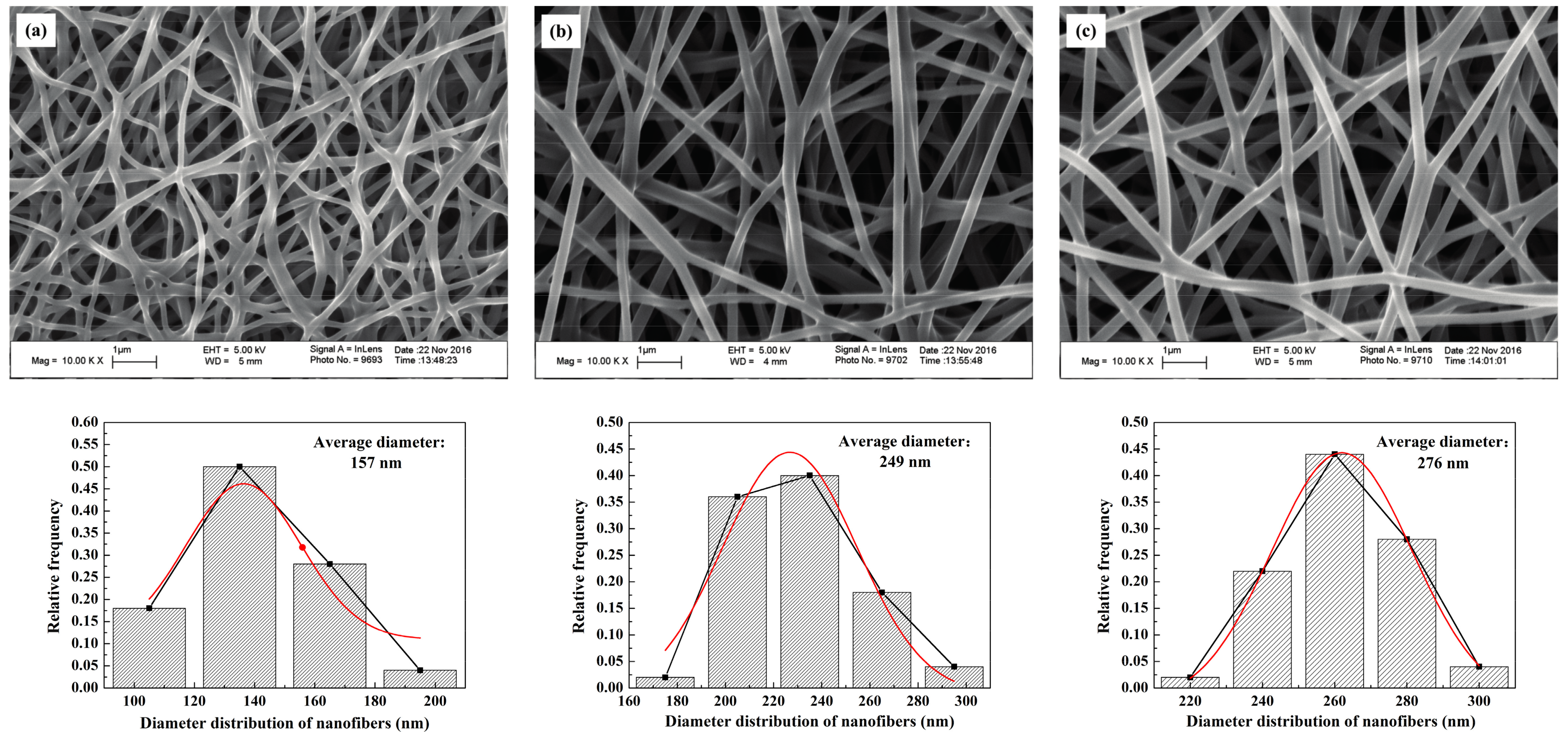
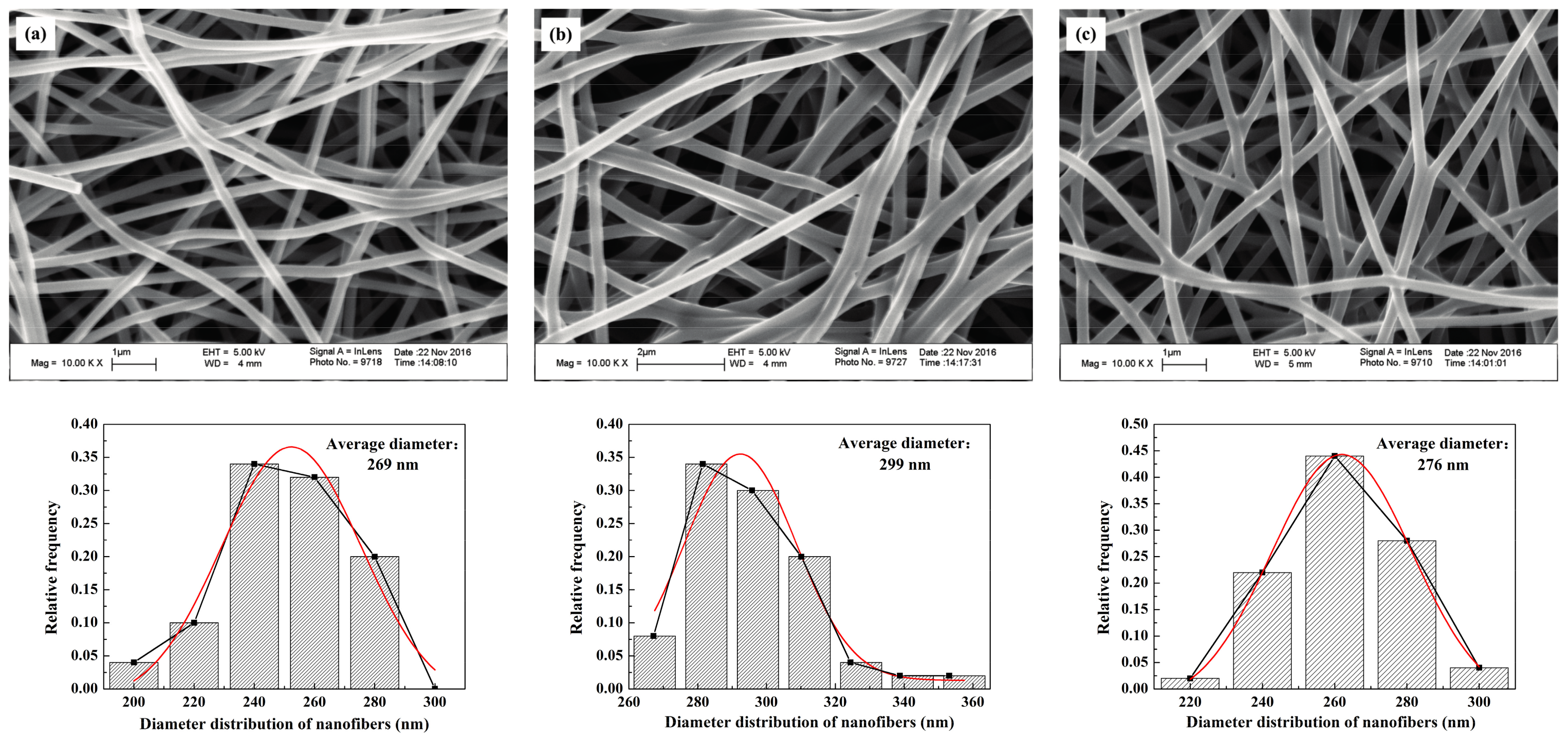
The SEM images of the self-developed CNWs and diameter distribution of nanofibers with different PAN concentrations are shown in
Figure 1. The nanofibers in this material have a regular and flexuous fibrous morphology, whose diameter becomes larger from 157, 249 to 276 nm as the PAN concentration increases from 10.96% (lower concentration,
CL), 13.70% (moderate concentration,
CM) to 16.44% (higher concentration,
CH). Sintering bonds are formed at the junctions of nanofibers, especially at a lower concentration of PAN, i.e.,
CL. This phenomenon is greatly relieved as the PAN concentration increases. The final fiber diameter is subject to the diameter of the micro droplet separated when spinning. The solution concentration relates to the viscosity, electrical conductivity and surface tension of the samples [
13]. Using a more concentrated solution makes it more difficult to separate the smaller droplets so as to increase the fiber diameter.
Table 1 lists some physical properties of the CNWs, including the penetrating time of a 4 μL droplet of 4 mol/L methanol solution. On the basis of the wettability test, the self-made CNWs have an unstable hydrophilicity. The indicator will gradually penetrate into the samples as time progresses.
Table 1 indicates that a higher concentration relates to a shorter penetrating time. Especially when the
CL is used, it yields a result several times larger than that of the
CM and
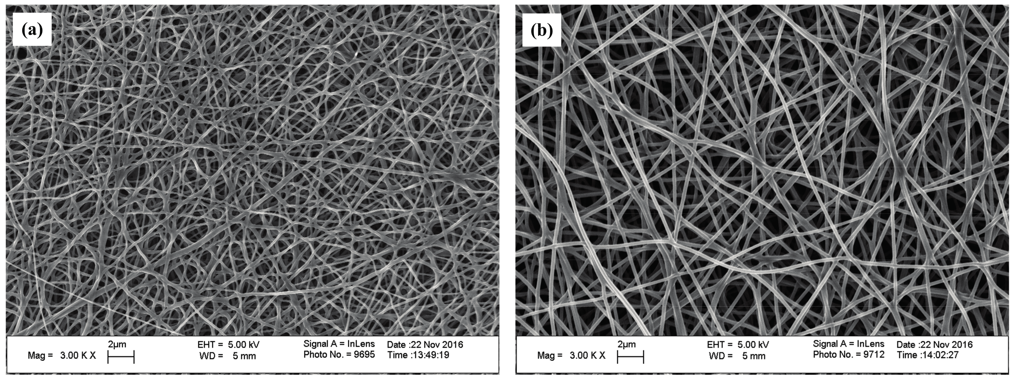
CH. This is because a smaller nanofiber diameter directly results in a more compact structure. Moreover, the sintering bonds tend to lower the porosity of the CNWs and thus reduce the permeability of the material to some extent. As shown in
Figure 2, it is evident that the
CL has a smaller diameter, lower porosity and higher compactness. The thickness of the sample increases from 42.61 to 116.49 μm with the increase in solution concentration, due to a larger diameter of fibers and more layers of stacked fibers. Besides, as shown in
Table 1, the electrical resistance of the CNW sample is influenced by the status of fiber distribution to a large extent since a higher compactness level and more sintering pastes will lead to a lower electrical resistance, which is helpful to improve the performance of current transfer. Furthermore, these CNW samples are quite light weight with a level of approximately 0.1 g.
The SEM images of the CNWs and diameter distribution of nanofibers in correspondence with different carbonizing temperatures are shown in
Figure 3. Generally, there is no apparent difference in the micro structures between the samples. The values of pore size and diameter are insensitive to the change of temperature. Besides, the levels of sintering bonds and porosities are similar to each other when different temperatures are used. In contrast, the electrical resistance of each sample decreases dramatically with the increase in carbonizing temperature, as the resistivity of the
TL,
TM and
TH are 123.33 × 10
−3, 6.15 × 10
−3 and 1.92 × 10
−3 Ω·m, respectively. This is because the hydrogen, oxygen and nitrogen can react under a high-temperature condition and fade away so that the proportion of carbon will increase substantially after 800 °C to cause a sharp drop in its proportion [
14]. This explains why the use of
TL yields a higher electrical resistance in the presence of a higher nitrogen ratio.
TH reacts at a relatively high carbonizing temperature which brings about a lower electrical resistance. In the temperature range from 800 to 1250 °C, the increase of carbonizing temperature is beneficial to the improvement of conductivity.
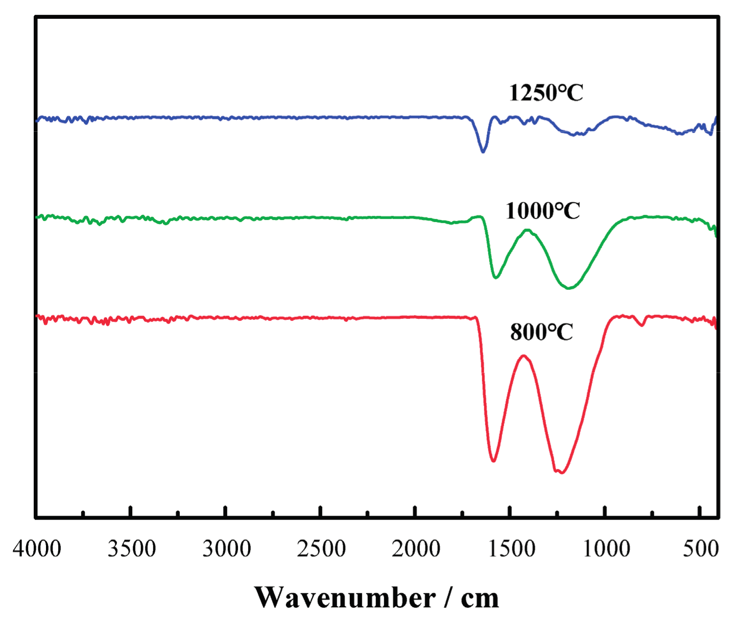
As shown in
Figure 4, with the increase in carbonizing temperature, the absorption peaks of -COO- band characteristics at 1220 cm
−1 and -C=N- features in the band at 1590 cm
−1 decrease significantly. This indicates the increased growth in the degrees of cyclization, deoxygenization and denitrification reaction to reach a higher level of carbonization of the samples.
2.2. Effects of the PAN Concentration on the Performance of DMFCs
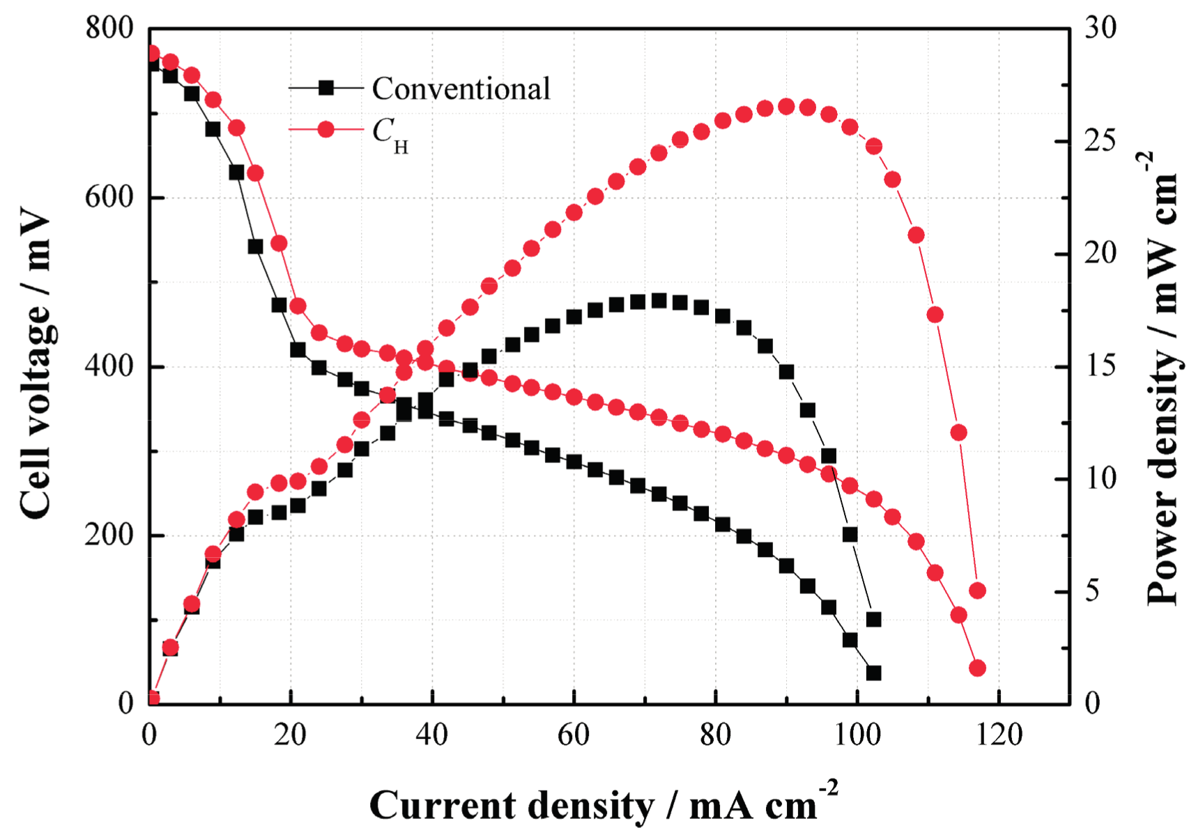
In order to evaluate the effect of the CNWs on the performance of a DMFC, the cell performance curves were measured when 2 mol/L methanol was used.
Figure 5 compares the performances of the cells with
CH and the conventional structure. As can be seen, the power density of the DMFC with
CH is much higher than that without
CH at 2 mol/L. Such performance improvement benefits from the use of
CH which helps increase the methanol mass transfer resistance and thus limit the MCO degree as well as improve the performance due to its internal porous structure.
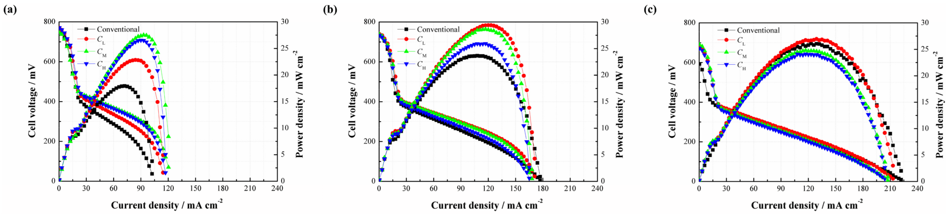
Since the CNWs are proved to benefit the performance of the DMFC, it is necessary to investigate the effect of the PAN concentration on the performance of the DMFC (see
Figure 6). As shown in
Figure 6a, three different types of CNW-based DMFCs yield a higher cell performance than the conventional setup at 2 mol/L. It is understandable that the CNWs play the role of methanol barrier to directly increase its mass transfer resistance. Besides, the hydrophilcity of the CNWs can also facilitate the water transport but indirectly inhibit the methanol transfer [
15]. These two aspects are both beneficial to alleviate the MCO. The peak power densities of
CL,
CM and
CH are 22.85, 27.53 and 26.55 mW/cm
2, whereas the conventional DMFC yields 17.93 mW/cm
2. In contrast, the samples based on
CL,
CM and
CH improve by 27.44%, 53.54% and 48.08%, respectively. This is because the sintering degree of
CL is high and the diameter of its nanofiber is smaller. As a result, the methanol transfer resistance becomes higher, so the MCO is greatly restricted by its compact structure. However, in the meantime, mass transfer becomes more difficult. In this case, the methanol supplement may not be sufficient in the fuel cell reaction at the anode, especially when a low methanol concentration is used. This means that the cell also possibly suffers from fuel starvation. Conversely, the sintering degree of
CH is much lower and its fiber diameter is larger than
CL. In other words, the methanol transfer resistance can be much lower in this situation, which helps accelerate the chemical reaction, facilitate the cell performance, but possibly brings about a higher MCO degree. The different behaviors verify that the mass transfer mechanism is a critical issue for a passive DMFC. The use of
CM produces the highest peak power density due to its moderate sintering degree and suitable size of the carbon nanofiber. An appropriate mass transfer resistance is able to not only meet the demand of methanol supplement but also alleviate MCO effectively. In this study, it is recommended to use the CNWs, especially the pattern of
CM, to improve the cell performance at a lower methanol concentration.
When the methanol concentration rises to 4 mol/L, it can be found that three different types of DMFCs with the CNWs still achieve higher peak power densities than that of the conventional DMFC. However, the performance gap becomes smaller, as shown in
Figure 6b. On the other hand, the cell performances from high to low are
CL,
CM and
CH. This phenomenon can be explained as follows. When the concentration reaches 4 mol/L, the methanol transfer to the anode catalyst layer becomes easier. This is also the case for the process of MCO. The negative effect of methanol starvation is greatly reduced while MCO is more and more severe. In the case of
CL, it has a relatively high mass transfer resistance to inhibit the methanol penetration from the anode to the cathode, which helps limit the MCO as much as possible and thus yields a better performance.
However, as shown in
Figure 6c, it is observed that the performance of
CL is slightly higher than that of the conventional one as the fuel concentration rises to 6 mol/L, while
CM and
CH exhibit even worse performances. This is because the internal reaction in the fuel cell becomes intense, consuming more methanol and generating more CO
2. The unmodified structure of the DMFC makes the CO
2 bubbles escape more easily from the diffusion layer to the outside compartment. However, the use of CNWs is not beneficial to CO
2 removal. On one hand, it increases the mass transfer resistance of bubble extrusion from the gas diffusion layer into the flow field. On the other hand, the hydrophilic surface favors the formation of CO
2 bubbles of smaller size and more uniform distribution [
16,
17]. As time progresses, small and separate bubbles, attached onto the inside wall of the CNWs, increasingly gather together, which will raise the internal pressure and block the feeding path of methanol fuel. Moreover, the water produced at the cathode should be removed as quickly as possible, otherwise it will hold back oxygen intake. Under the effect of the CNWs, the process of water backflow from the cathode to the anode becomes difficult due to the increase of anode pressure. Though the existence of CNWs greatly restrains the MCO, it also hinders the removal of the product. This section demonstrates that the cell performance is determined by diverse factors under different conditions.
2.3. Effects of the Carbonizing Temperature on the Performance of DMFCs
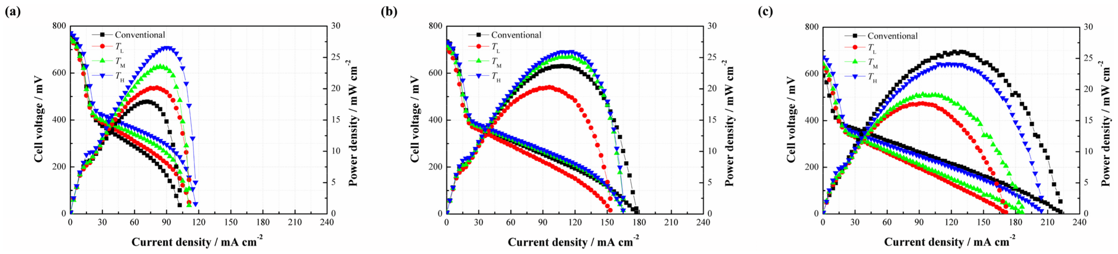
This section focuses on how the cell performance varies with the change of carbonizing temperature.
Figure 7 illustrates the effects of different carbonizing temperatures on the cell performance. As shown in
Figure 7a, three different types of DMFCs with the CNWs yield better cell performances than that of the conventional DMFC without additional CNW at a methanol concentration of 2 mol/L. This result shows a consistent trend with the cases related to different PAN concentrations, and further verifies that the CNWs are helpful to improve the performance of DMFCs. The peak power densities of TL, TM and TH are 20.17, 23.52 and 26.55 mW/cm
2, corresponding to a 27.44%, 53.54% and 48.08% improvement respectively, compared with the conventional DMFC. There is no apparent difference in the micro structure, including nanofiber diameter, porosity and the thickness among three patterns of the CNWs with different carbonizing temperatures shown in
Table 2. This means that the mass transfer resistances of these samples are nearly equal to each other. However, the conductivity of each sample increases rapidly as the temperature increases. This phenomenon highlights why the TL performs much worse than the other two samples due to its high electrical resistance in the presence of a higher nitrogen ratio. The TH reacts at a relatively high carbonizing temperature which leads to a lower resistance and yields the best cell performance.
As shown in
Figure 7b, the performances of
TM and
TH are slightly higher than that of the conventional DMFC at 4 mol/L, while
TL shows a lower performance due to the large difference of electrical resistance among the samples. From
Figure 7c, it is observed that the positive effect of the CNW even disappears as the concentration of the methanol solution rises to 6 mol/L. This phenomenon is like the effect of PAN concentration at the same methanol concentration, which can be explained by the CO
2 trapping behaviors.
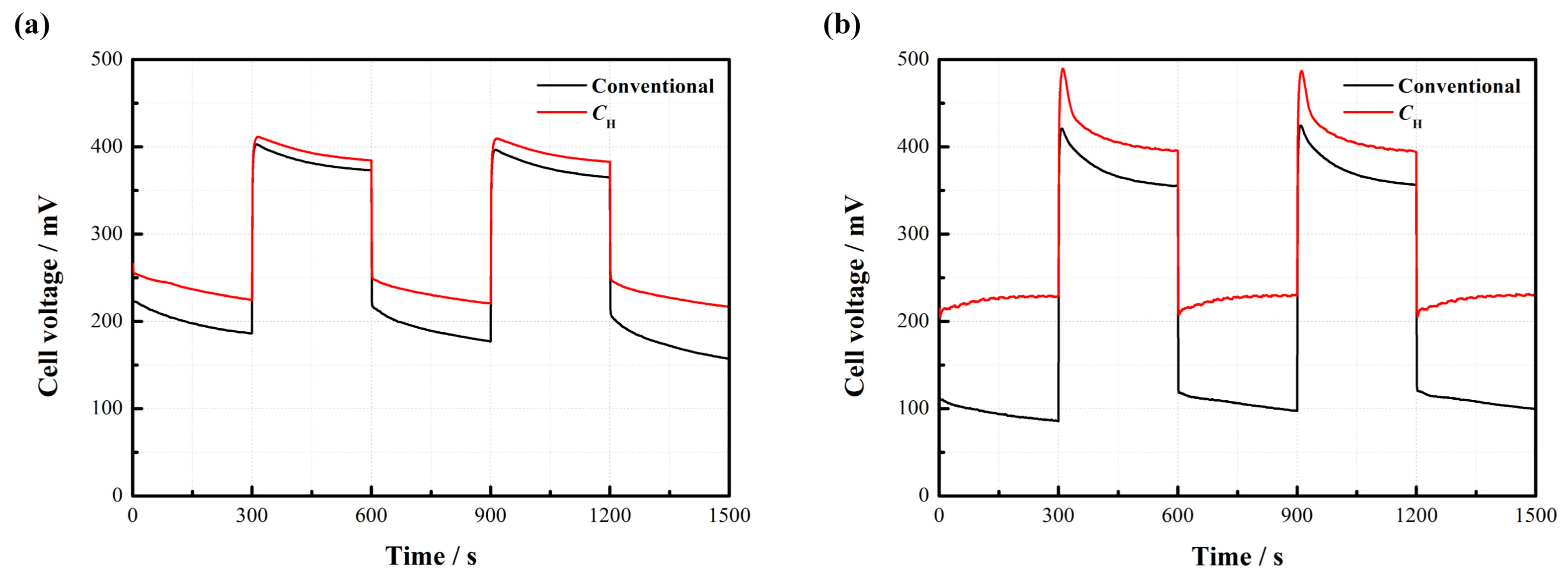
2.4. Dynamic Characteristics
Figure 8 displays the dynamic characteristics of the passive DMFCs with and without
CH.
Figure 8a indicates that the cell voltage instantly changes with the repeated change of current density from 20 to 50 mA/cm
2 at 2 mol/L. Both kinds of cells maintain a relatively stable output in each steady state. It is observed that the cell with
CH works more stably and has less voltage loss compared to the conventional pattern without
CH.
Figure 8b further suggests that the voltage of the DMFC with
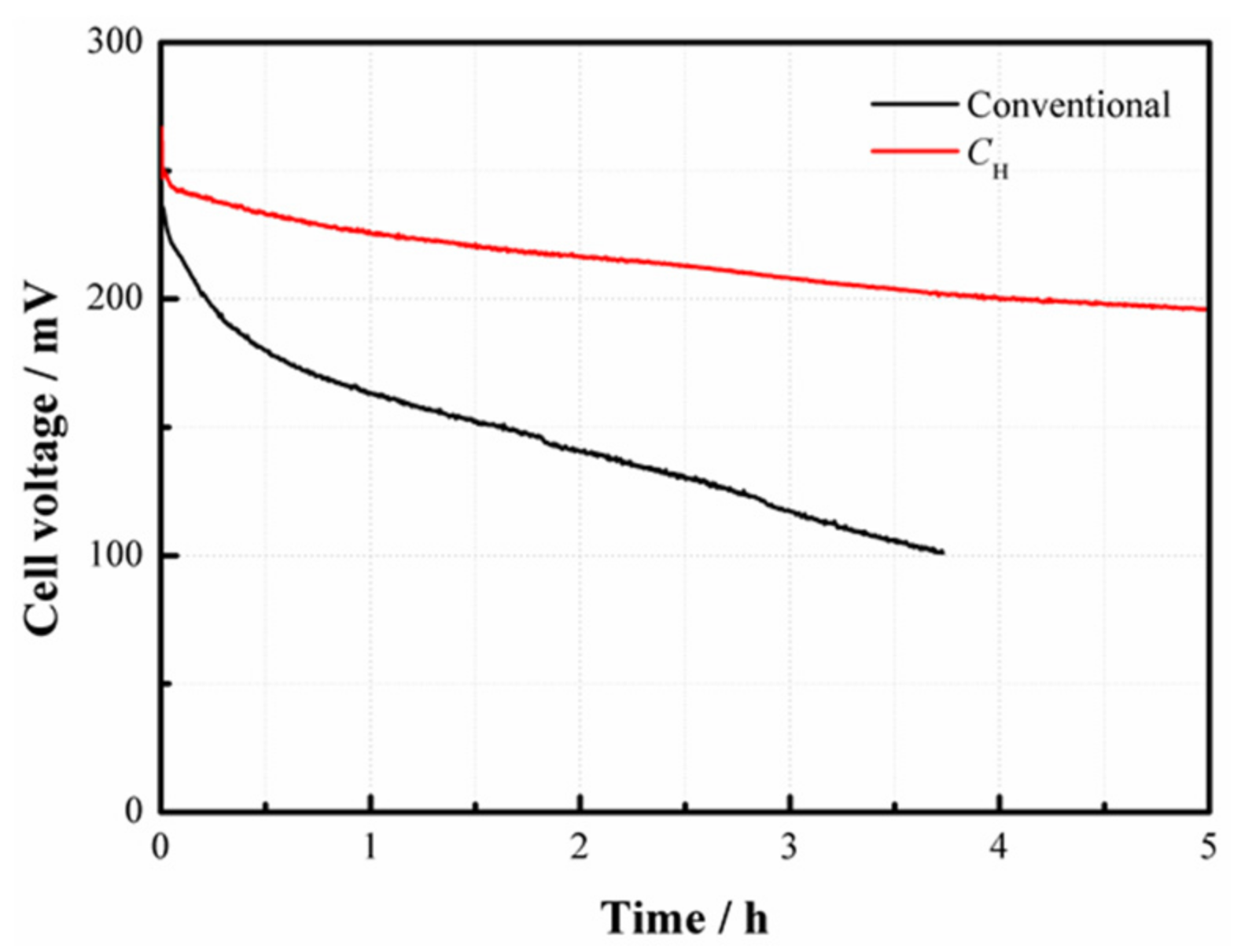
CH responds more rapidly to the change of current density. When the current density sharply drops from 80 to 20 mA/cm
2, an apparent voltage overshoot happens. After this, the cell voltage gradually drops down until reaching a new stable level. This phenomenon can be attributed to the fact that an abrupt decline of the current load reduces the demand for methanol supply, so the MCO may inevitably build up, thus inducing more voltage losses. Once a new concentration balance between the anode and the cathode is formed, the cell performance can be stabilized. The overshoot degree is closely related to the fluctuation amplitude of the current density [
18]. In addition, it is noted that the average cell voltage output with
CH is much higher than the conventional one, especially during the high-current operation.


