Article

Efficiency Enhancement of a Low-Voltage Automotive Vacuum Cleaner Using a Switched Reluctance Motor

1
Koha-A Jung Gong, Ltd., 20, Cheomdan venture-ro 60 beon-gil, Buk-gu, Gwangju 61009, Korea
2
Department of Electrical Engineering, Chonnam National University, Gwangju 61186, Korea
3
Department of Electrical Engineering, Wonkwang University, Iksan 54538, Korea
*
Author to whom correspondence should be addressed.
Energies 2016, 9(9), 692; https://doi.org/10.3390/en9090692
Submission received: 5 July 2016 / Revised: 19 August 2016 / Accepted: 23 August 2016 / Published: 30 August 2016
(This article belongs to the Special Issue Energy Saving Design for Manufacturing Process, Product, and System)

Abstract

:
A recent increase in the number of diverse leisure activities and family outdoor activities has increased the need for the automobile-embedded vacuum cleaner. To date, this technology has not been applied in Korea and development efforts are not underway. Many of the existing portable cleaners connecting to the lighter jack of the vehicle use a direct current motor (DC motor). However, they do not have sufficient suction power to satisfy consumers; moreover, they have low durability and efficiency. In this paper, we therefore propose a technology for increasing the efficiency of the low-voltage automobile vacuum cleaner by replacing the existing DC motor with a switched reluctance motor (SRM), which has superior durability and efficiency.

1. Introduction

A recent increase in the number of diverse leisure activities and family outdoor activities has increased the need for the automobile-embedded vacuum cleaner. To date, this technology has not been applied in Korea and development efforts are not underway. Many of the existing portable cleaners connecting to the lighter jack of the vehicle use a direct current motor (DC motor). However, they do not have sufficient suction power to satisfy consumers; moreover, they have low durability and efficiency on account of their brush–commutator structure. Thus, a low-cost motor with a more durable mechanical structure and high-speed capability is required to replace the existing DC motor. To address this need, the switched reluctance motor (SRM) is proposed, which is a low-cost, mechanically sturdy motor that is robust to harsh environments such as high temperature. It is also superior to DC motors because it does not have a permanent magnet or coil in its rotor. Furthermore, it has high reliability on account of its simple structure, and has a wide range of speeds. It is therefore suitable for high-speed operations and offers a torque per unit volume and efficiency that are higher than those of DC motors [1,2,3,4,5,6,7,8].
Owing to the above advantages, SRM applications are expanding to home appliances, such as vacuum cleaners. In addition, SRM is suitable for high-temperature environments and environments with severe vibration such as in vehicles. In this paper, we therefore propose a high-speed, high-efficiency, SRM drive system for application to the automotive vacuum cleaner as well as the replacement of the DC motor. We designed a prototype SRM that conforms to the related design goals. We employed the finite element method (FEM) in a magnetic field analysis [9]. Additionally, we verified the performance of the proposed vacuum cleaner by carrying out a suction power test to compare our prototype to DC-motor-type vacuum cleaners.

2. SRM Design for Low-Voltage Automotive Vacuum Cleaner

2.1. Design Requirements

The SRM motor of a 300 W automotive vacuum cleaner operates at low voltage and a relatively high current. The design specifications of the proposed DC motor includes a stator out diameter of 45 mm, a rotor out diameter of 29.2 mm, a slot of 2 ea, a resistance of 0.070 ohm/25 °C, an air gap of 0.30 mm, a magnet of 0.42 Br as shown in Table 1. The design specifications of the proposed SRM includes input voltage of 24 V, a maximum current of 40 A, a rated speed of 32,000 rpm, a suction efficiency of 40%, a stator out diameter of 57.1 mm, a rotor out diameter of 25.4 mm, a slot of 4 ea, an air gap of 0.265 mm as shown in Table 1. To create a product that is stable, while showing the maximum efficiency in a similar suction power range, a high-efficiency driver and motor with low-voltage drop was exclusively designed for the low-voltage and high-current application.

2.2. Analysis of Characteristics
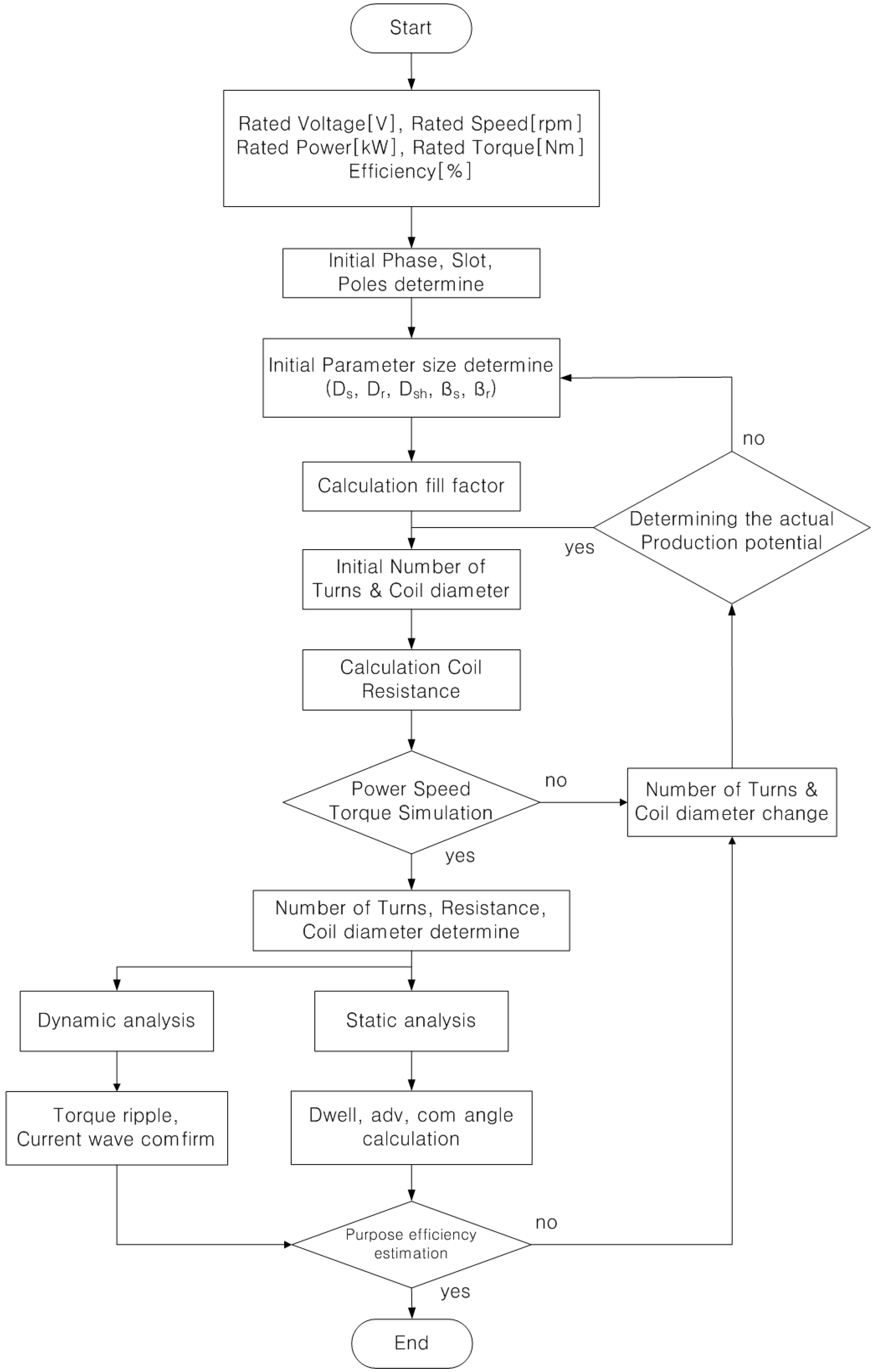
In terms of the combination of stator and rotor poles of SRM for the vacuum cleaner, previous study results show that the pole combinations of 4/2, 6/4, 8/6, and 12/8 have the highest practicality [10,11,12]. The speed characteristics should be superior and the price should be competitive to satisfy the requirements for the design of the SRM for a low-voltage automotive vacuum cleaner. The two-phase 4/2 SRM shown in Figure 1 is adopted [13].
The two-phase 4/2 SRM is competitively priced. Moreover, its pole combination design provides superior speed characteristics because the number of switching devices is two to four times less than those of the 6/4, 8/6, and 12/8 combinations. It is thus suitable for high-speed applications of 20,000 rpm or higher. However, a dead band, where no torque is generated, exists with the two-phase 4/2 SRM. This issue can be solved through a stator and rotor shape design and control technique.

3. SRM Design

We adopted the two-phase 4/2 SRM by reviewing the suitable pole combinations in accordance with the proposed design requirements. It was designed by selecting the outer diameter of the rotor, the outer diameter of the stator, and the stack. The yoke, pole arc, and number of windings were determined based on the selected outer diameters of the stator, rotor, and stack. FEM was performed with the parameters finally determined. The design algorithm is as shown in Figure 2.
Using the design algorithm, the design was repeatedly refined until the maximum efficiency was achieved. To this end, we first determined the combination of pole arcs and the numbers of slots and poles of the stator and rotor. This determination was made when we selected the rated operation specifications, thereby determining the dwell values as well as the advance and commutation angles required for motor control. This task was achieved through a static simulation. We confirmed the values of torque ripple, current, magnetic flux density, and current density through a dynamic simulation.

3.1. Basic Design of SRM

Based on the prototype design criteria, the design parameters are as shown in Figure 3. The design elements are detailed in Section 3.1.1, Section 3.1.2, Section 3.1.3 and Section 3.1.4.

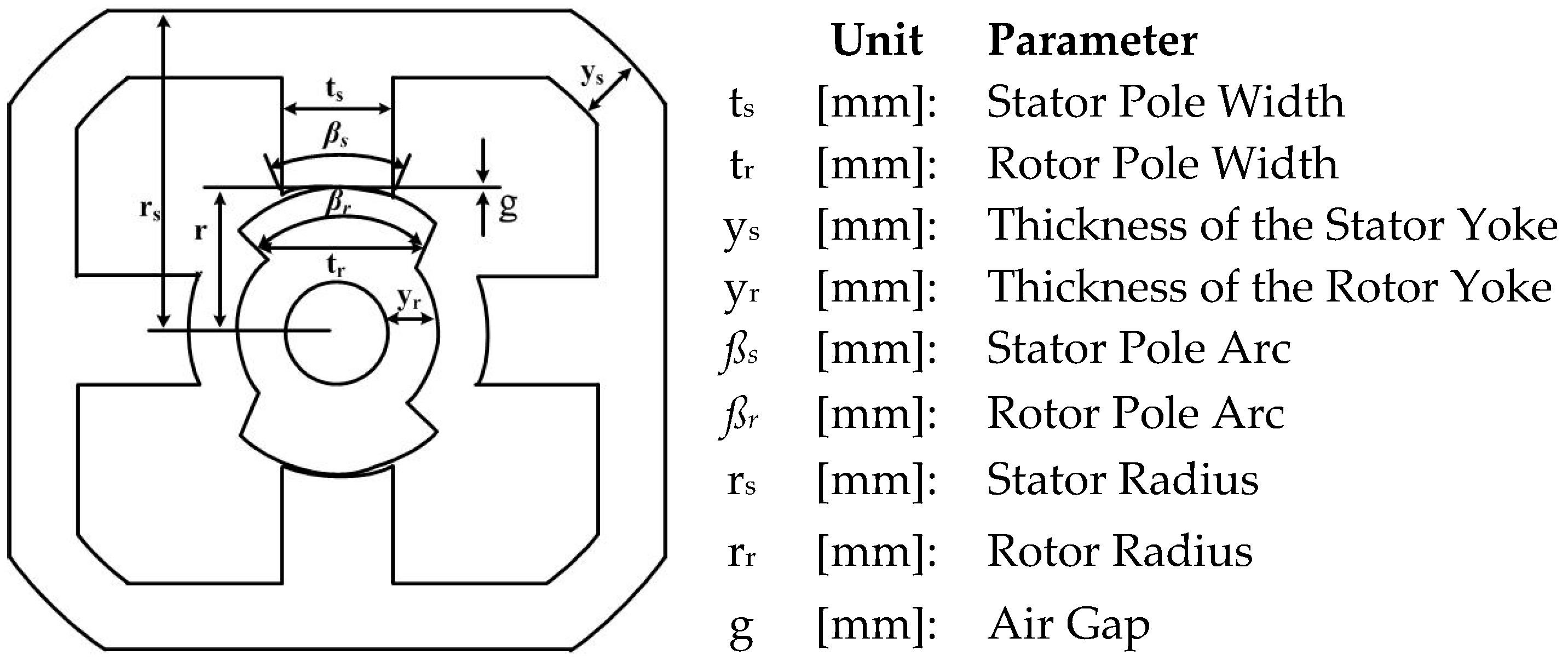
3.1.1. Stator and Rotor Yoke and Pole Width

The pole width ( t s ) is the area where the two magnetic fluxes that have passed through the yoke are joined. The yoke thickness should be approximately twice the pole width during the basic design. The initial values of the stator pole width and rotor pole width are determined in accordance with Equations (1) and (2), respectively, which can be changed during the design details. The yoke is the parameter that affects the rigidity, vibration, and noise of the motor and it should be determined from Equations (3) and (4):
t s > y s > 0.5 t s
0.75 t r > y r > 0.5 t r
t s = 2 ( r s + g ) sin ( β s 2 )
t r = 2 ( r r + g ) sin ( β r 2 )

3.1.2. Stator Rotor Pole Arc
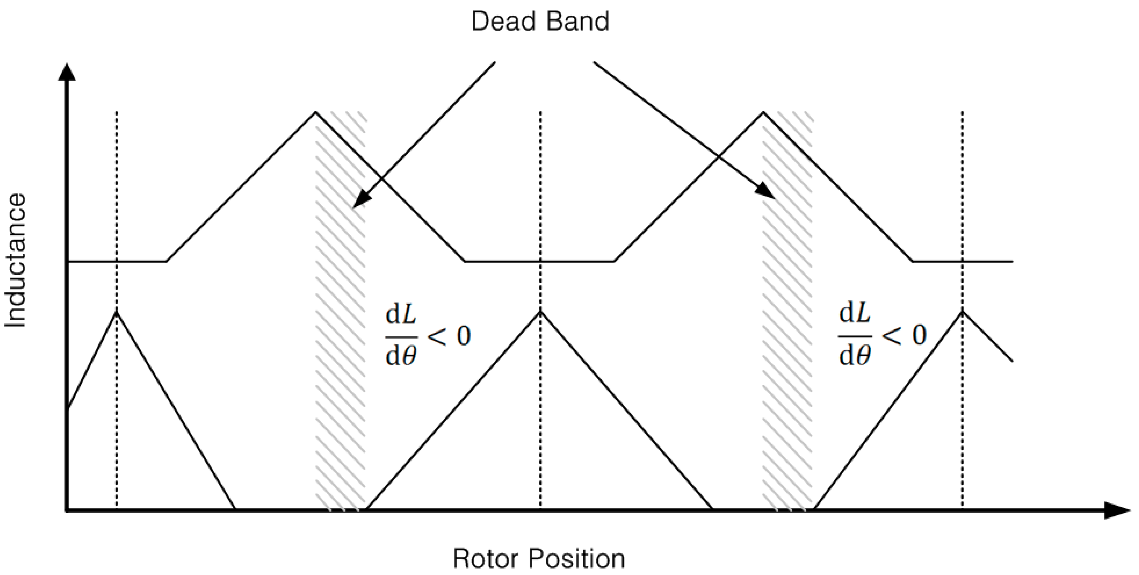
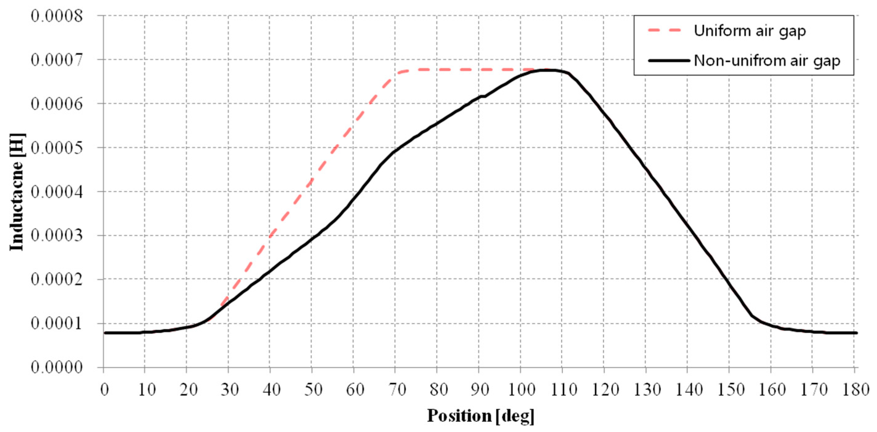
The pole arc is an important parameter that affects the width of both the pole and the yoke as well as the rated capacity and torque. Although the torque and capacity can be increased if the pole arc increases as the width increases, it is difficult to design the rated current, since the total slot area decreases. Accordingly, the pole arc is designed within the general range of Equation (5):
2 π N r β r > β s

3.1.3. Air Gap

Regarding the air gap length, approximately 0.5% of the rotor diameter is set as the basic size. The performance is superior when the leakage flux is small. Nevertheless, if the air gap in Equation (6) is small, it is difficult to uniformly maintain the air gaps in the manufacturing process, which leads to serious vibration. If the air gap is large, less vibration is generated. Nonetheless, the control characteristics deteriorate because the voltage-current condition worsens. The air gap length is thus determined to be between 0.2 and 0.3 mm when considering the manufacturing and processing technologies
g = 0.005 × D r

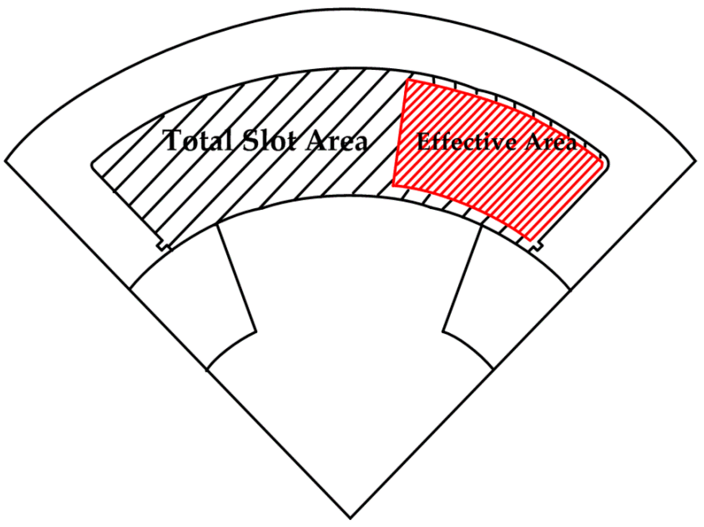
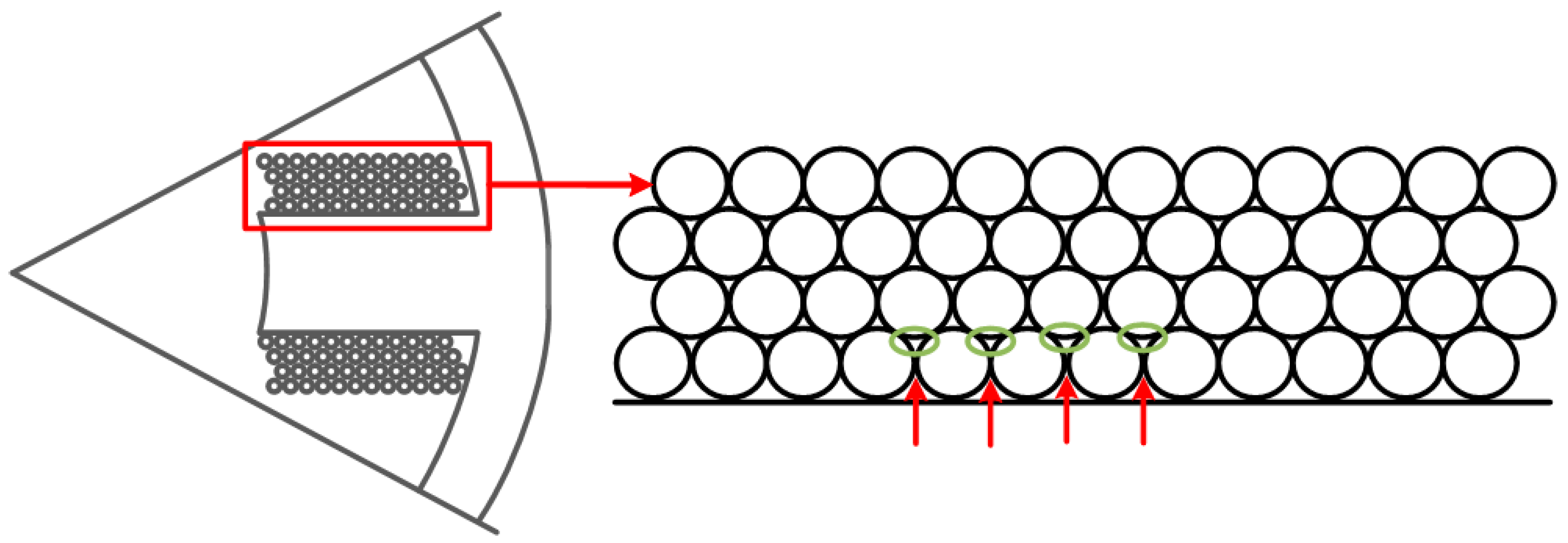
3.1.4. Slot Fill Factor

The effective area of winding is determined by drawing the actual winding over the total slot area, as shown in Figure 4. The effective area is determined to be between 30% and 40% of the general total slot area.
The winding method used for SRM is basically a concentrated winding method, whereby the wire is wound on the stator pole. Each pole has one coil. SRM coils can be wound in advance and inserted into the poles; they do not affect each other. Accordingly, the maximum slot occupation rate that can be obtained depends on the winding method, the type and amount of insulation, and the type of conductor. In terms of the actual slot occupation rate, the range in which the wire can be stably wound is determined to be 40% of the total slot area:
N p = 2 × H wire × W wire × P f × ( 4 π ( D wire ) 2 )
Here, H wire is the height accounted for by the winding in the stator pole, W wire is the thickness of the winding accounted for by the stator pole, P f is the packing factor, and D wire is the winding diameter. In addition, Equations (8) and (11) represent H wire and W wire , respectively:
H wire = ( d s D si 2 )
In addition, d s [in] is the stator pole height and D s i [in] is the stator inner diameter:
d s = D s 2 × y s
D si = D r + 2 × g
W wire = ( D r 2 × P s 2 ) ( S wire 2 )
In Equation ( 12 ) , P s [deg] is the stator pole pitch and S wire [in] is the space between the windings, for which a value between 0.1 and 0.2 is entered because it is very small. S wire is described in Figure 5, which shows the space between the windings:
P s = ( 360 ( N s × β s ) ) N s

3.2. Optimum SRM Design

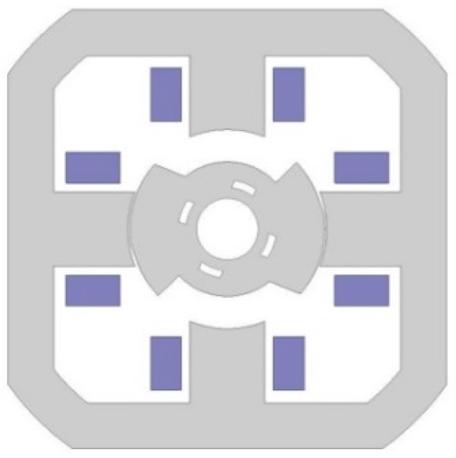
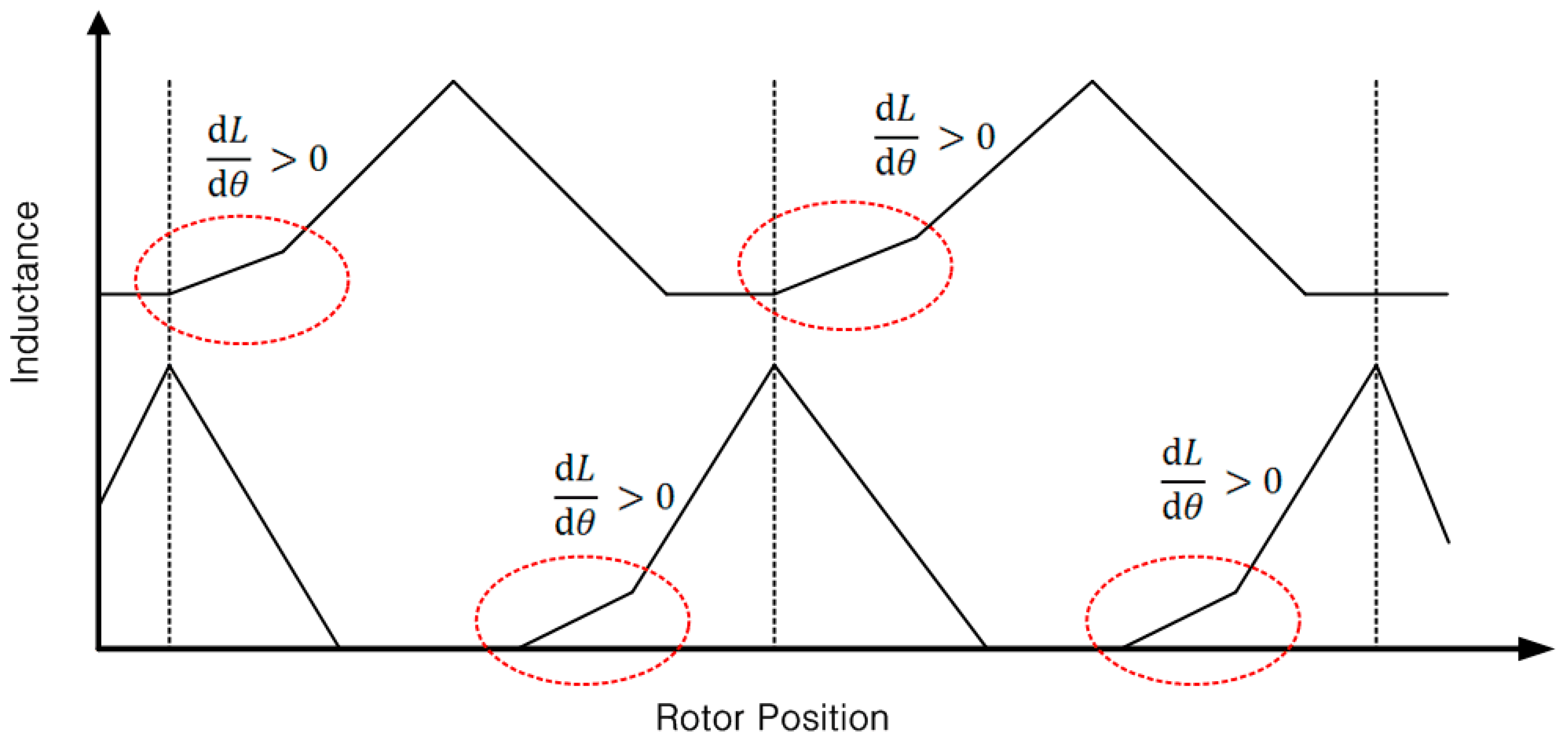
3.2.1. Structural Characteristics of Two-Phase SRM

In the case of a two-phase SRM, if the air gap of the rotor is uniform, the inclination of the inductance graph becomes 0. Moreover, dead bands, where no torque is generated, occur, as shown in Figure 6. If a section exists in the rotor position where no torque is generated during the initial operation, a significant problem can occur during the initial operation. To resolve the problem in which no torque is generated, the air gaps in the rotor are designed differently to ensure a variety in the size of the air gaps when the stator and the rotor are aligned.
If the size of the air gaps differs, the graph is asymmetrically generated, as shown in Figure 7. Furthermore, constant torque is generated at all times. The problem arising when operating the motor can be resolved because the area where the inclination of the inductance graph is 0 disappears.
Figure 8 shows comparison of the inductance profiles for the two different air gap configurations: (1) an inductance profile with the uniform air gap (dotted curve); (2) inductance profile with the non-uniform air gap (solid curve). In case of the uniform air gap, the average torque is higher than that of the non-uniform air-gap case as the slope of the inductance profile. However, the non-uniform air gap structure has a minimum dead-zone (flat inductance at peak) compared to the uniform air gap structure, and hence the non-uniform air gap excels in self-starting capability.
Figure 9 is the two different air gap configurations: (a) cross section of the non-uniform air gap; (b) cross section of the uniform air gap. Figure 10 is the cross section of the prototype rotor model.

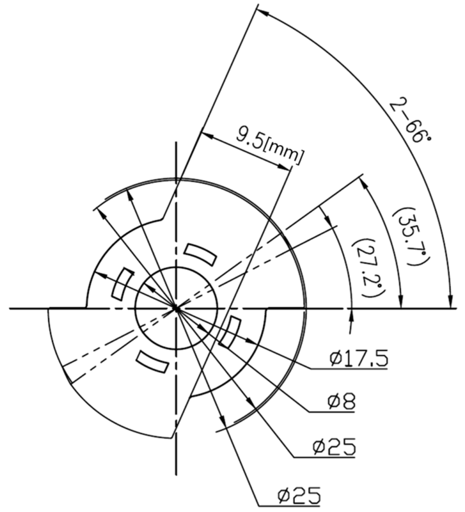
3.2.2. Design Details

Table 2 presents data of the 4/2 SRM obtained via the process illustrated in Figure 2. These data comprise the content of the basic design in Section 3.1. The outer diameter of the stator was previously determined at the initial stage based on the housing space of the cleaner set. In the detail design, the outer diameter of the rotor is set to be no larger than 50% of the stator outer diameter because it is operated at a high speed of 32,000 rpm.
In addition, owing to the characteristics of low voltage whereby a high current is applied, further space is needed in the fill factor of the winding to accommodate the correction of the number of turns and coil diameter. The pole arc of the rotor is set to be approximately twice that of the stator pole arc to supplement the characteristics of the 4/2 combination. The torque ripple of this combination is large as the rotor pole arc is set to be wider than that of the stator pole arc.
Moreover, the two-phase SRM should be designed so that the inductance curve is not structurally symmetric, unlike a general three-phase SRM. Therefore, the pole arc of the rotor is designed to be divided into three levels. The maximum air gap is determined to be 0.45 mm and the minimum air gap is determined to be 0.265 mm. Furthermore, in order to ensure the inclination of the inductance is uniform with the maximum air gap, the air gap of the rotor is designed to gradually change to equal the maximum air gap by varying the center points of the circles.

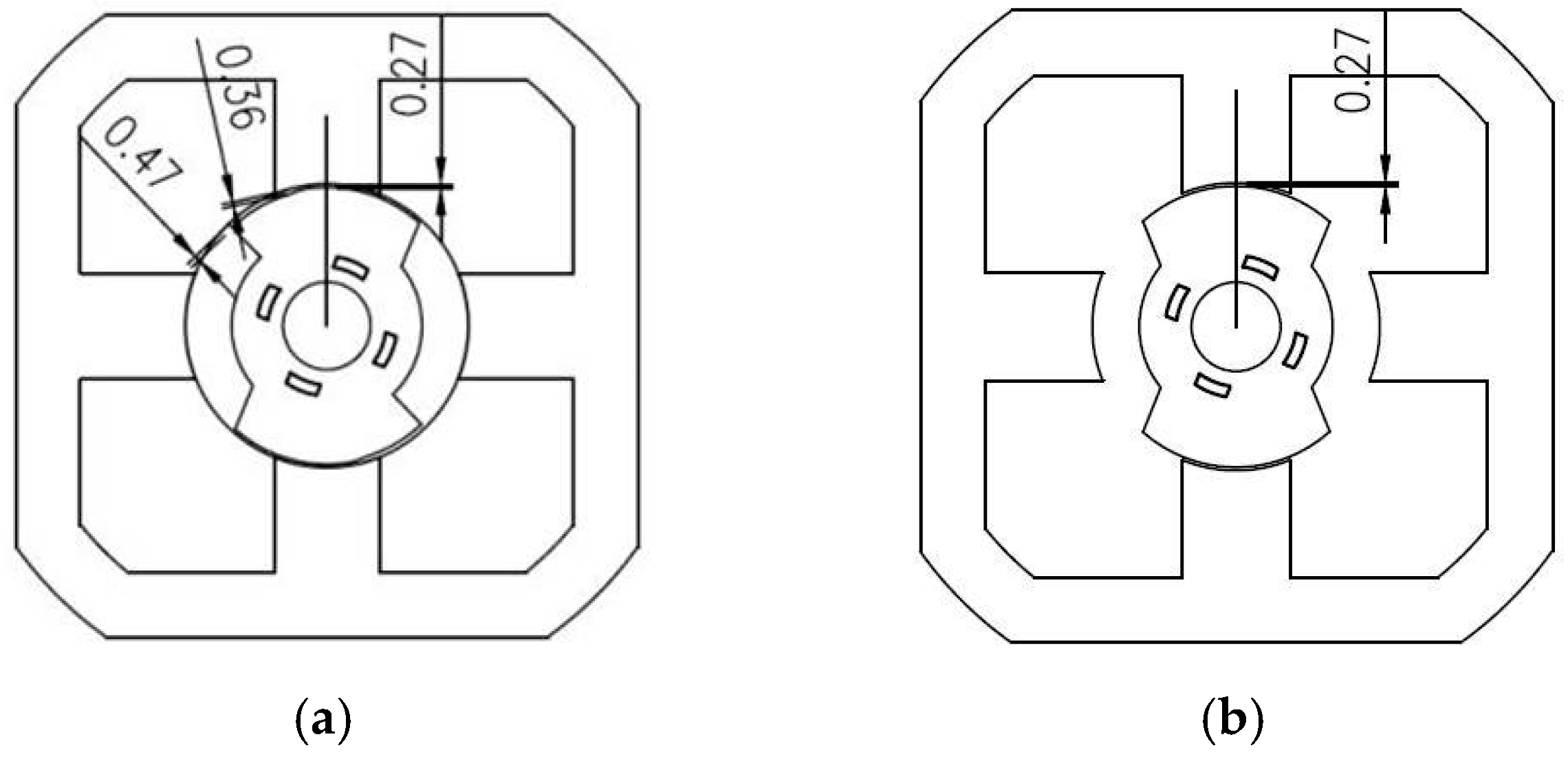
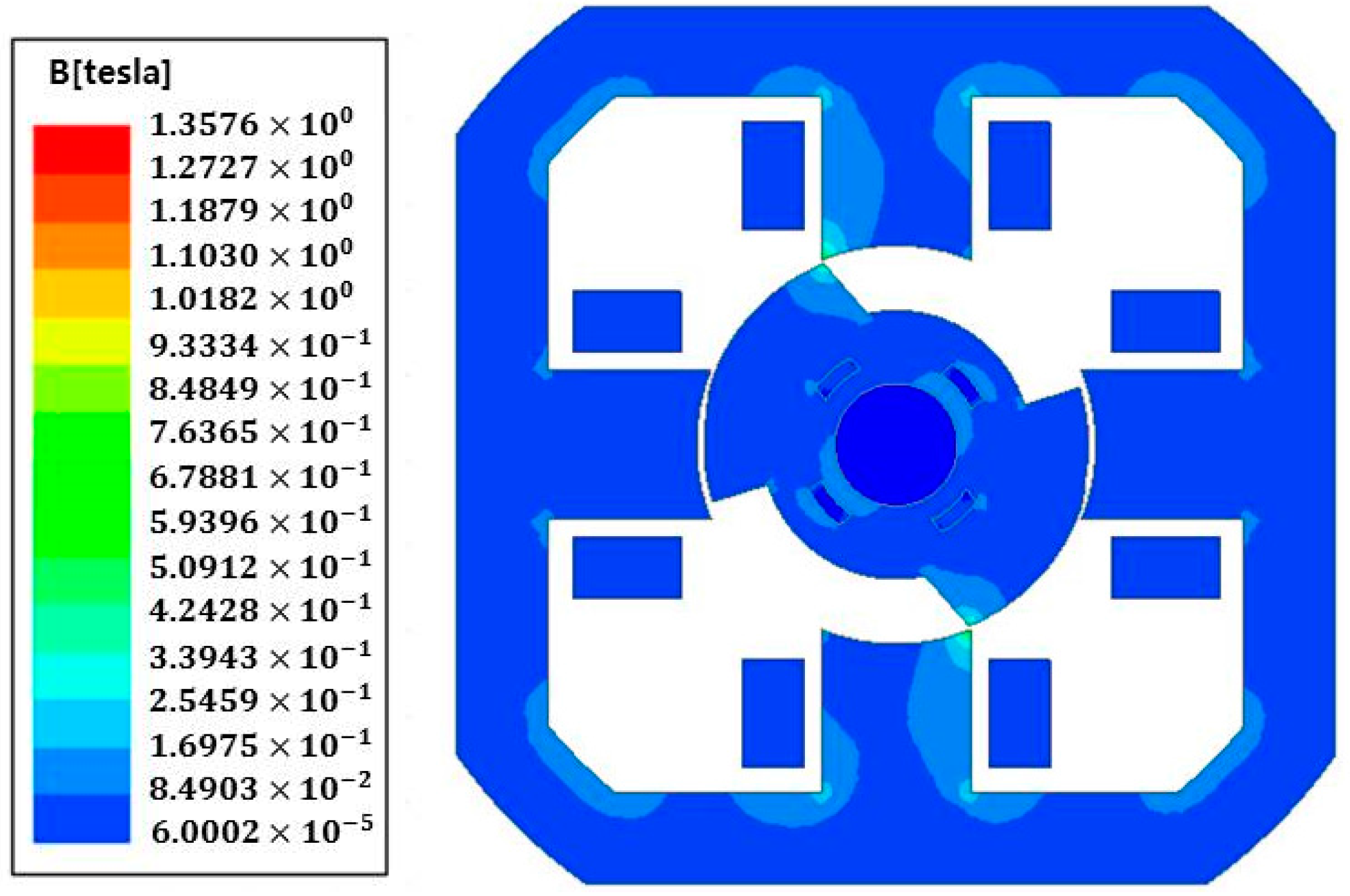
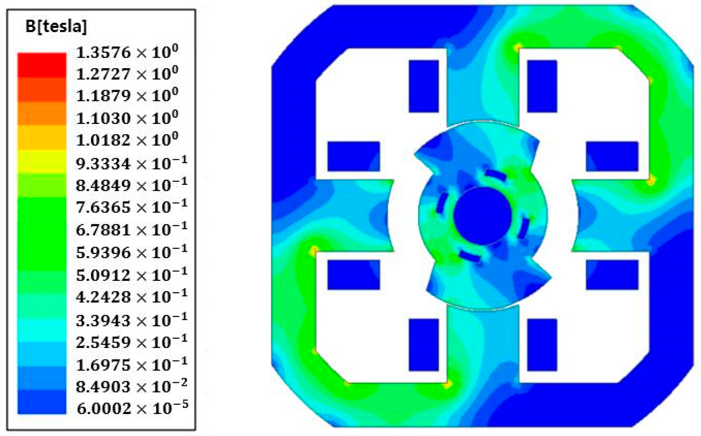
3.3. Finite Element Method of the Designed SRM

The FEM is utilized in the SRM design to obtain an approximate value by subdividing a large problem into finite elements that are interconnected. We apply simple equations to each of these elements, assemble the simple equations that model these finite elements, and solve the equations. FEM is performed in the order of modeling, mesh work, analysis, and visualization. Figure 11 shows the inductance profile value, which is the resultant value of FEM, while Figure 12 depicts the torque profile [14,15,16].
Figure 13 From finite element method (FEM) simulation results with 40 degree of advanced angle and 40 degree of commutation angle, the average torque and the torque ripple at 40 degree of advanced and commutation angles results in 0.0502 N·m and 27.94% respectively.
Figure 14 and Figure 15 show the magnetic flux density values at the moments when the stator and rotor are aligned and not aligned, respectively.
The maximum flux density is approximately 1.35 T. It is evident that the magnetic flux density is designed so that the electrical steel plate is not saturated during an operation. This is accomplished by setting the value to be no greater than 1.5 T, which is the saturated magnetic flux density of the material 35PN230 used for the production.

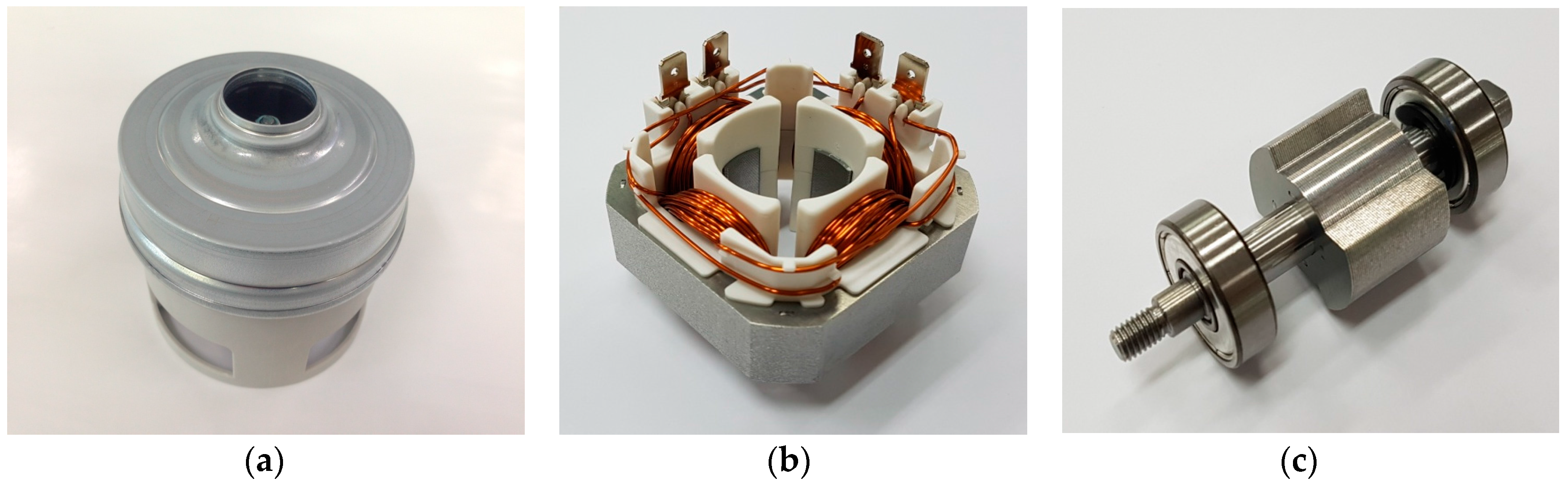
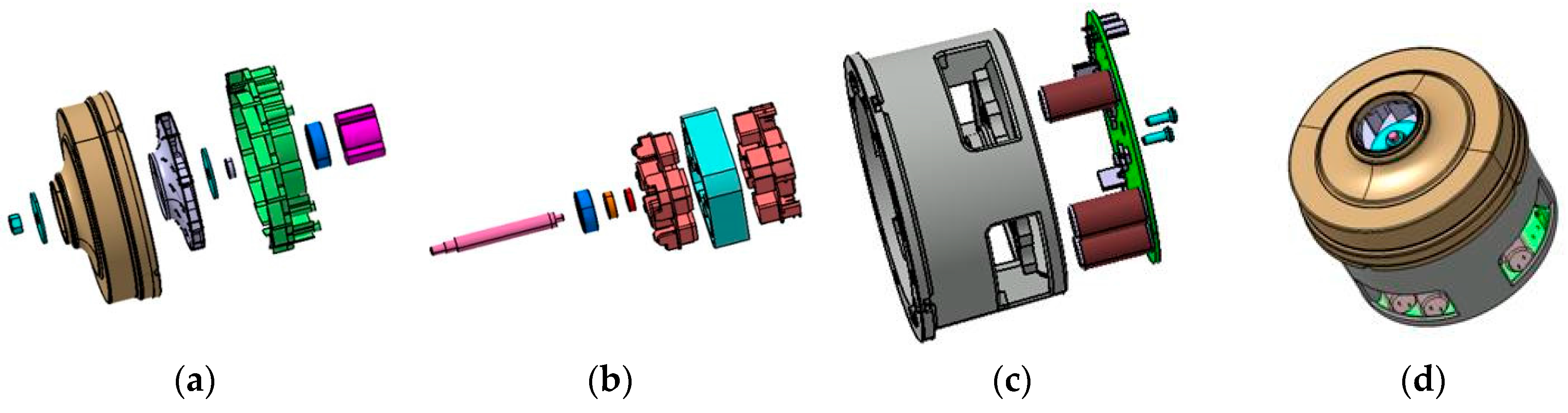
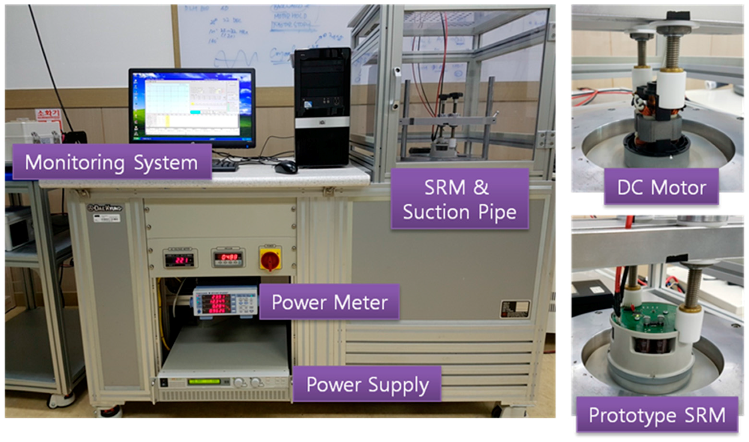
4. Prototype Production

Figure 16 depicts the 3D modeling of the designed SRM automotive vacuum cleaner, while Figure 17 shows the produced prototype based on the designed model. Figure 16a illustrates the impeller, which is the most important mechanical part of the cleaner. It determines the path of air intake and exhaust, as well as the suction rate. The inverter is attached to the motor housing. The air flow of the vacuum cleaner has a direct effect on the inverter printed circuit board (PCB); neither an external device for cooling the inverter nor an inverter housing is required.

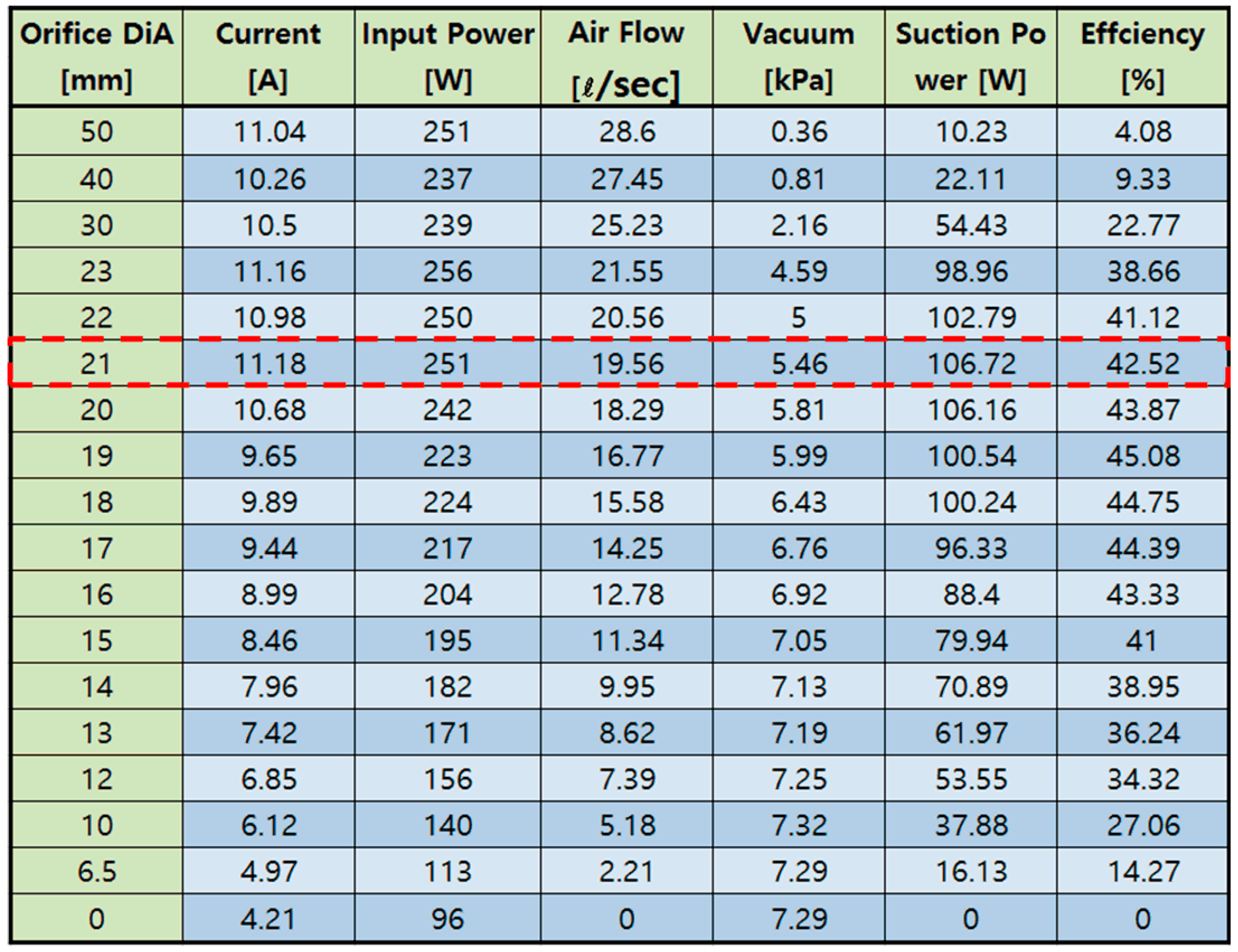
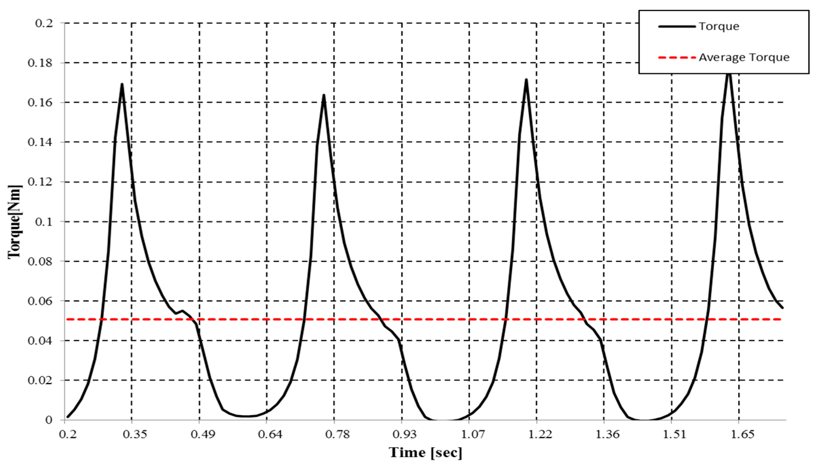
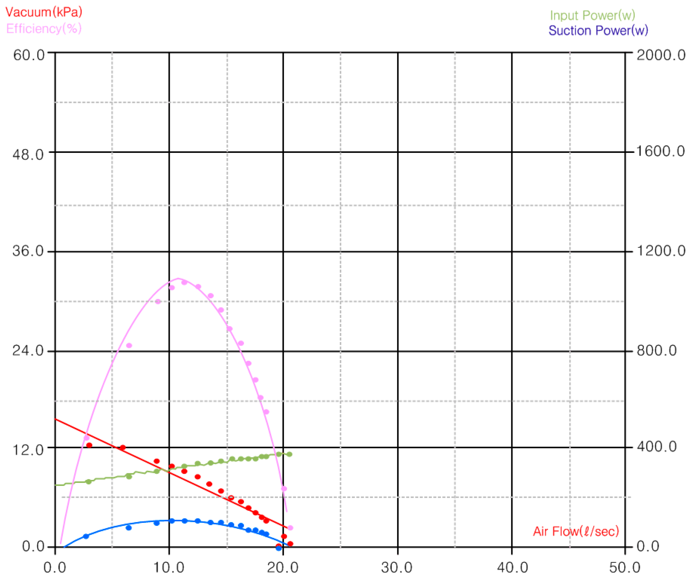
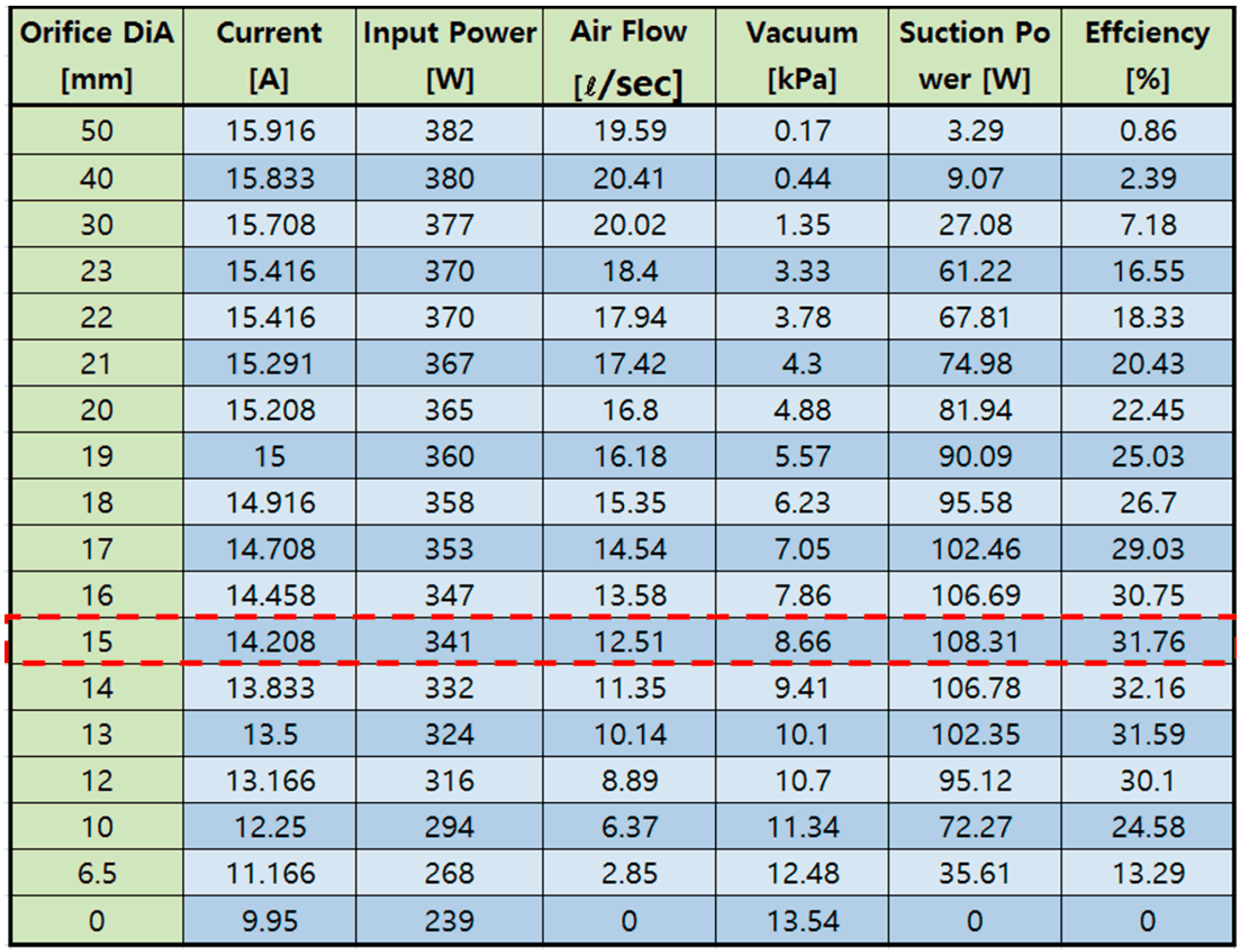
5. Analysis of Prototype Motor Characteristics

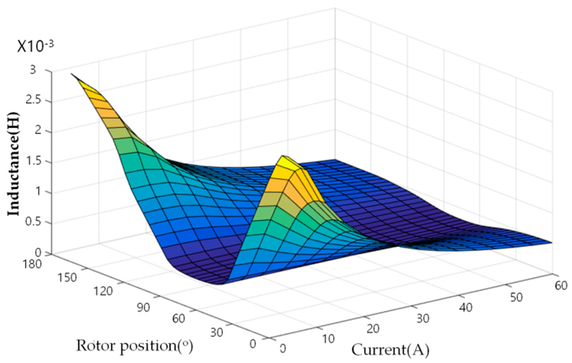
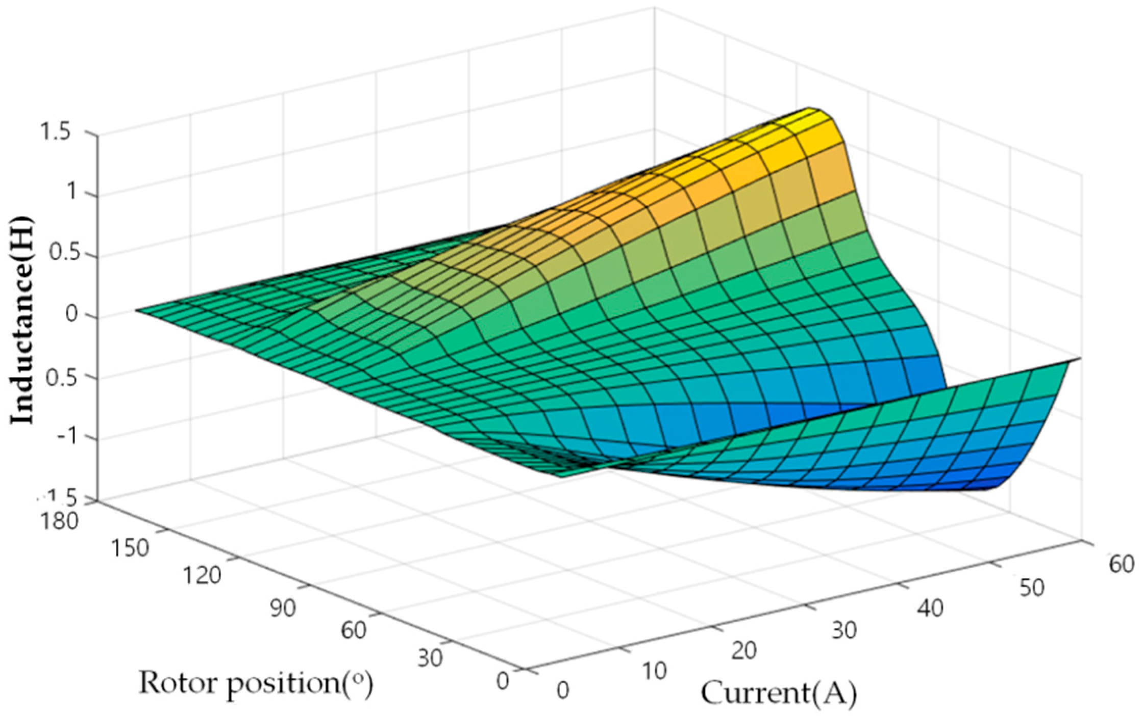
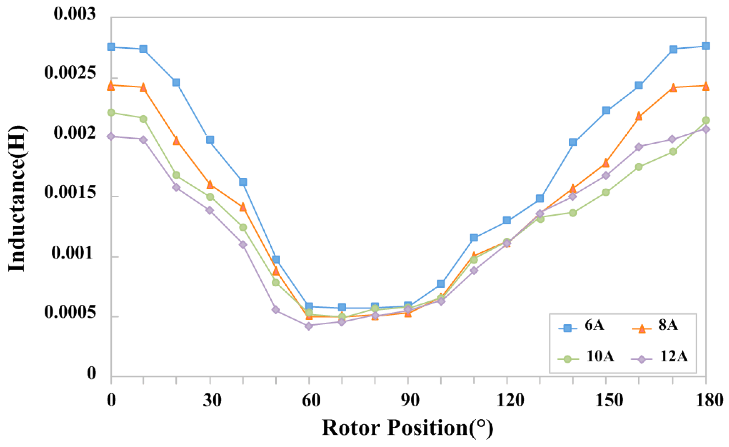
5.1. Measurement of the Prototype Motor Inductance

The measured inductance profiles of the produced prototype motor are shown in Figure 18. The inductance of the SRM is a function of the rotor position and exciting current. It is an important parameter that determines the performance of the drive. The maximum inductance measured is 0.002753 mH and the minimum inductance is 0.000425 mH. While the measured inductance profiles are comparable to the inductance profiles obtained from the FEM simulation of Figure 19, the simulation and measurement results differ, mainly due to the manufacturing and measuring errors.

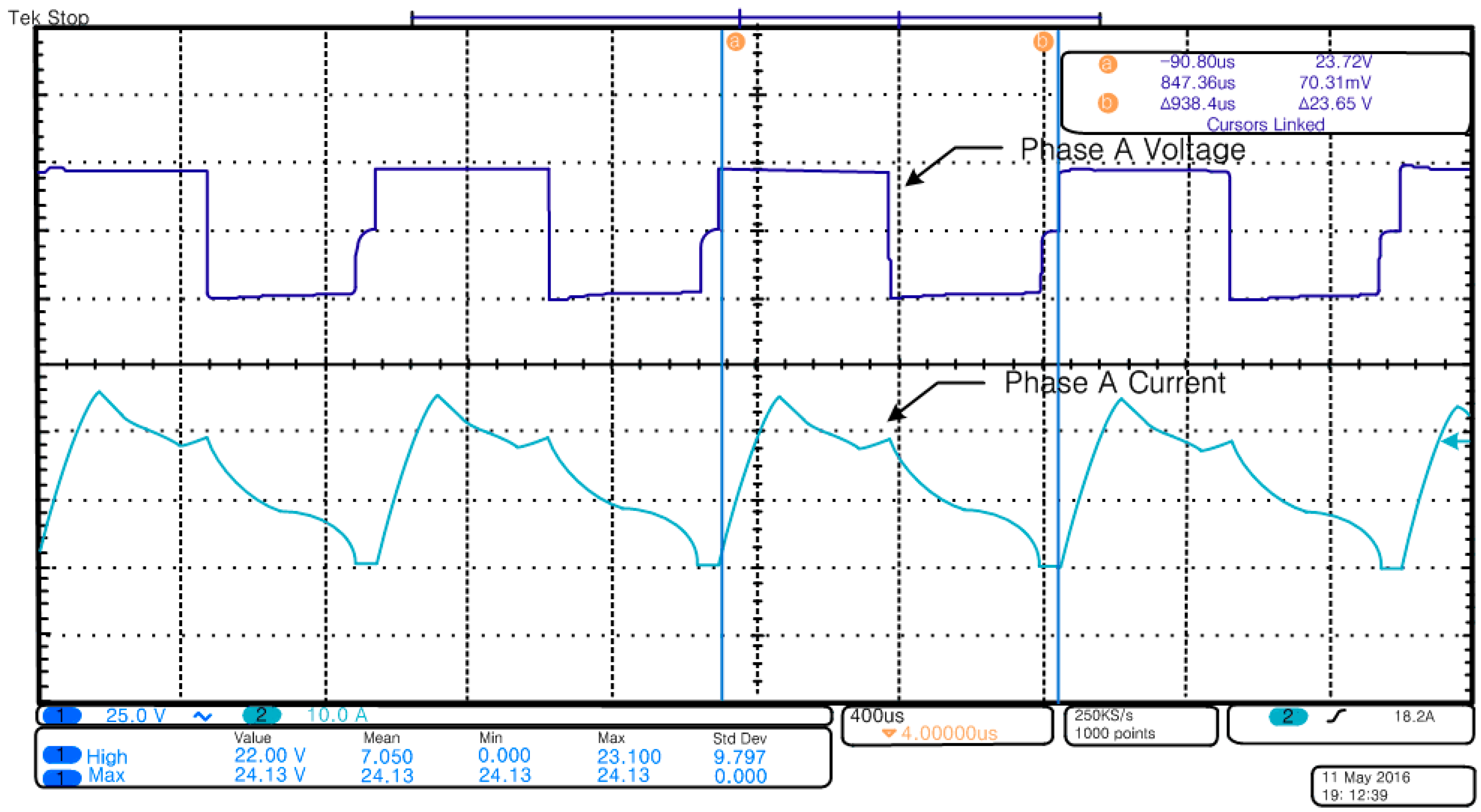
5.2. Driving Test of the Prototype Two-Phase 4/2 pole SRM and DC Motor

The driving waveform of the SRM was measured before comparing the suction efficiency performance to check the driving performance of the produced prototype SRM. The waveform in Figure 20 shows the phase voltage and phase current of an SRM phase, respectively. The results confirm that the motor is stably driven at the rated speed of 32,000 rpm by adjusting the advance angle at full duty [17,18,19,20,21,22,23,24].
Figure 21 depicts a suction power tester that can be used to check the suction power of the cleaners. The cleaner was connected to the tester in the standard measurement condition and continuously operated at the rated voltage and rated speed. From that point, the air volume and amount of vacuum characteristics were measured by adjusting the air volume control valve from the deployed position to the fully closed position when the temperature became almost constant.
In addition, the digital measurement device attached to the cleaner automatically measured the power consumption, current, and suction power. The highest points of the motor performance and suction power could thereby be accurately found. The current suction power tester comprises a specimen mount, power supply, power meter, and monitoring system. Here, a measurement was taken by adjusting the intake size in 18 steps from 50 mm to 0 mm. A comparative test was performed accordingly for the suction power of the DC motor and prototype SRM.
We compare the efficient points at the maximum suction power in the suction power comparison test data in Figure 22, Figure 23, Figure 24 and Figure 25. The DC motor shows suction power and efficiency of 108.31 W and 31.76%, respectively, when the orifice diameter is 15 mm. Meanwhile, the prototype SRM shows suction power and efficiency of 106.72 W and 42.52%, respectively, when the orifice diameter is 21 mm. These results demonstrate that, although the DC motor suction power is greater than that of the prototype SRM by approximately 2 W, the prototype SRM shows increased efficiency by approximately 11% compared to that of the DC motor. Furthermore, it is evident that the efficiency of the prototype SRM is greater than that of the DC motor in the range of 22 mm to 17 mm, which is the overall use range of the orifice diameter as well as that across the whole band.

6. Conclusions

In this paper, we have presented our designed and produced prototype SRM for a low-voltage automotive vacuum cleaner. We verified its performance by conducting a comparative load tests with a DC motor using a suction power tester. To validate the design and accurate analysis of the motor, the magnetic and torque characteristics obtained from FEM were used. The SRM was verified as having greater efficiency than the DC motor across the entire band using the suction power tester. It is thereby confirmed that SRM could replace the existing motor used for automotive low-voltage vacuum cleaners.

Author Contributions

All the authors contributed equally to this work. Han-Geol Seon conceived and wrote the manuscript, designed and performed the experiments. Man-Seung Han and JaeHyuck Kim contributed to the conceptual approach and provided important comments on the modeling and analysis. Hyun-Jin Ahn and Young-Cheol Lim conceived the outline, wrote and revised the manuscript. All the authors discussed the results and implications, and commented on the manuscript at all stages.

Conflicts of Interest

The authors declare no conflict of interest.

References

  1. Miller, T.J.E. Converter volt-ampere requirements of the switched reluctance motor drive. IEEE Trans. 1985, 5, 1136–1144. [Google Scholar] [CrossRef]
  2. Krishnan, R.; Materu, P. Design of a single-switch-per-phase converter for switched reluctance motor drives. IEEE Trans. 1990, 37, 469–476. [Google Scholar] [CrossRef]
  3. Wallace, R.S.; Taylor, D.G. A balanced commutator for switched reluctance motors to reduce torque ripple. IEEE Trans. Power Electron. 1992, 7, 617–626. [Google Scholar] [CrossRef]
  4. Wallace, R.S.; Taylor, D.G. Low torque ripple switched reluctance motors for direct drive robotics. IEEE Trans. Robot. Autom. 1991, 7, 733–742. [Google Scholar] [CrossRef]
  5. Krishnamurthy, M.; Edrington, C.S.; Emadi, A.; Asadi, P.; Ehsani, M.; Fahimi, B. Making the case for applications of switched reluctance motor technology in automotive products. IEEE Trans. Power Electron. 2006, 21, 659–675. [Google Scholar] [CrossRef]
  6. Hu, Y.; Song, X.; Cao, W.; Ji, B. New SR drive with integrated charging capacity for plug-in hybrid electrical vehicles. IEEE Trans. Ind. Electron. 2014, 6, 5722–5731. [Google Scholar] [CrossRef]
  7. Bilgin, B.; Emadi, A.; Krishnamurthy, M. Design consideration of switched reluctance machines with higher number of rotor poles. IEEE Trans. Ind. Electron. 2012, 59, 3745–3756. [Google Scholar] [CrossRef]
  8. Dos Santos, F.L.M.; Anthonis, J.; Naclerio, F.; Gyselinck, J.J.C.; van der Auweraer, H. Multiphysics NVH modeling: Simulation of a switched reluctance motor for an electrical vehicle. IEEE Trans. Ind. Electron. 2014, 61, 469–476. [Google Scholar] [CrossRef]
  9. Miller, T.J.E.; McGilp, M. Nonlinear theory of the switched reluctance motor for rapid computer-aided design. IEEE Proc. B 1990, 137, 337–347. [Google Scholar] [CrossRef]
  10. Emadi, A.; Young, L.J.; Rajashekara, K. Power electronics and motor drives in electric, hybrid electric and plug-in hybrid electric vehicles. IEEE Trans. Ind. Electron. 2008, 55, 2237–2245. [Google Scholar] [CrossRef]
  11. Xue, X.D.; Cheng, K.W.E.; Cheung, N.C. Multi-objective optimization design of in-wheel switched reluctance motors in electric vehicles. IEEE Trans. Ind. Electron. 2010, 57, 2980–2987. [Google Scholar] [CrossRef]
  12. Krishnan, R.; Arumugan, R.; Lindsay, J.F. Design Procedure for Switched Reluctance Motors. IEEE Trans. Ind. Appl. 1988, 24, 456–461. [Google Scholar] [CrossRef]
  13. Komatsuzaki, Y. Cross current for parallel operating three-phase inverter. IEEE Power Electron. Spec. Conf. 1994, 943–950. [Google Scholar]
  14. Pollock, C.; Willams, B.W. Power convertor circuit for switched reluctance motors with the minimum number of switches. IEEE Proc. B 1990, 137, 373–384. [Google Scholar] [CrossRef]
  15. Schramm, D.S.; Williams, B.W.; Green, T.C. Torque ripple reduction of switched reluctance motors by phase current optimal profiling. Proc. IEEE PESC 1992, 2, 857–860. [Google Scholar]
  16. Orthmann, R.; Schoner, H.P. Turn-off angle control of switched reluctance motors for optimum torque output. Proc. EPE 1993, 6, 20–55. [Google Scholar]
  17. Chen, L.; Mercorelli, P.; Liu, S. A Kalman Estimator for Detecting Repetitive Disturbances. In Proceedings of the IEEE American control conference, Portland, OR, USA, 8–10 June 2005.
  18. Mercorelli, P. An Adaptive and Optimized Switching Observer for Sensorless Control of an Electromagnetic Valve Actuator in Camless Internal Combustion Engines. Asian J. Control. 2014, 16, 959–973. [Google Scholar] [CrossRef]
  19. Mercorelli, P. An Anti-Saturating Adaptive Pre-action and a Slide Surface to Achieve Soft Landing Control for Electromagnetic Actuators. IEEE/ASME Trans. Mech. 2012, 17, 76–85. [Google Scholar] [CrossRef]
  20. Chladny, R.R.; Koch, C.R. Flatness-Based Tracking of an Electromechanical VVT Actuator with Disturbance Observer Feed-Forward Compensation. IEEE Trans. Control Syst. Technol. 2008, 16, 652–663. [Google Scholar] [CrossRef]
  21. Mercorelli, P.; Lehmann, K.; Liu, S. Robust flatness based control of an electromagnetic linear actuator using adaptive PID controller. IEEE Conf. 2003, 4, 3790–3795. [Google Scholar]
  22. De Santos, E.; Di Benedetto, M.D.; Pola, G. On Observability and Detectability of continuous-tim Switching Linear Systems. In Proceedings of the 42nd IEEE Conference on Decision and Control, CDC 03, Maui, HI, USA, 9–12 December 2003.
  23. Fabbrini, A.; Garulli, A.; Mercorelli, P. Trajectory Generation Algorithm for Optimal Consumption in Electromagnetic Actuators. IEEE Trans. Control Syst. Technol. 2012, 20, 1025–1032. [Google Scholar] [CrossRef]
  24. Velasco, C.I.H.; di Gaeta, A. Valve Position-based Control at Engine Key-on of an Electromechanical Valve Actuator for Camless Engines: A Robust Controller Tuning via Bifurcation Analysis. Asian J. Control 2016, 18, 868–887. [Google Scholar] [CrossRef]
Figure 1. Structure of the proposed two-phase 4/2 pole SRM.
Energies 09 00692 g001
Figure 2. SRM design flowchart.
Energies 09 00692 g002
Figure 3. Design parameters of the proposed two-phase 4/2 pole SRM.
Energies 09 00692 g003
Figure 4. Winding effective area.
Energies 09 00692 g004
Figure 5. Space between windings.
Energies 09 00692 g005
Figure 6. Uniform air gap inductance graph of the proposed two-phase 4/2 pole SRM.
Energies 09 00692 g006
Figure 7. Non-uniform air gap inductance graph of the proposed two-phase 4/2 pole SRM.
Energies 09 00692 g007
Figure 8. Comparison of the inductance profiles for the two different air gap configurations.
Energies 09 00692 g008
Figure 9. Cross section of the two different air gap. (a) Cross section with the non-uniform air gap; (b) Cross section with the uniform air gap.
Energies 09 00692 g009
Figure 10. Cross section of the prototype rotor model.
Energies 09 00692 g010
Figure 11. Inductance profile of the designed SRM.
Energies 09 00692 g011
Figure 12. Torque profile of the designed SRM.
Energies 09 00692 g012
Figure 13. Torque graph through analysis.
Energies 09 00692 g013
Figure 14. Aligned position flux density of the designed SRM.
Energies 09 00692 g014
Figure 15. Unaligned position flux density of the designed SRM.
Energies 09 00692 g015
Figure 16. 3D model structure of the automotive vacuum cleaner using the proposed SRM. (a) Impeller mechanism; (b) The two-phase 4/2 pole SRM; (c) Motor housing & integrated converter; (d) Two-phase 4/2 pole SRM 3D modeling.
Energies 09 00692 g016
Figure 17. Prototype SRM. (a) Outside view of SRM prototype; (b) Structure of stator; (c) Structure of rotor.
Energies 09 00692 g017
Figure 18. Measured inductance profiles.
Energies 09 00692 g018
Figure 19. Simulated inductance profiles using FEM.
Energies 09 00692 g019
Figure 20. Operating waveform of prototype SRM.
Energies 09 00692 g020
Figure 21. Suction power tester and DC motor/SRM sample.
Energies 09 00692 g021
Figure 22. DC Motor suction power graph.
Energies 09 00692 g022
Figure 23. Prototype two-phase 4/2 pole SRM suction power graph.
Energies 09 00692 g023
Figure 24. DC Motor suction power test data.
Energies 09 00692 g024
Figure 25. Prototype two-phase 4/2 pole SRM suction power test data.
Energies 09 00692 g025
Table 1. Specifications of the proposed switched reluctance motor (SRM) in accordance with the conventional direct current motor (DC motor).
ParametersDC MotorSRM
Input Voltage [V]2424
Input Current [A]1613
Rated Power [W]350300
Rated Speed [rpm]32,00032,000
Suction Power [W]106106
Suction Efficiency [%]3240
Stator Out Diameter [mm]4557.1
Rotor Out Diameter [mm]29.225.4
Slot [ea]24
Resistance [ohm/25 °C]0.0700.059
Air Gap [mm]0.300.265
Magnet [Br]0.42
Table 2. Design parameter results of the proposed two-phase 4/2 pole SRM.
ParameterValue (Target)Unit
Number of Stator PolesNs4ea
Number of Rotor PolesNr2ea
Stator Out DimensionDs57.1mm
Rotor Out DimensionDr23.949mm
Stator Pole ThicknessCth9.7mm
Stator Pole LengthLs10.596mm
Rotor Pole LengthLr4mm
Air Gap Lengthg0.286mm
Stack LengthLstk5.93mm
No. of Turns/PolesTp40turn
No. of Turns/PhasesTph80turn

