Article

Open Fault Detection and Tolerant Control for a Five Phase Inverter Driving System

1
Department of High-Speed Railroad Systems Research Center, Korea Railroad Research Institute, 176, Cheoldo Bangmulgwan-ro, Uiwang-si, Gyeonggi-Do 437-757, Korea
2
Department of Electrical and Computer Engineering, Ajou University, 206, World cup-ro, Yeongtong-gu, Suwon 443-749, Korea
*
Author to whom correspondence should be addressed.
Energies 2016, 9(5), 355; https://doi.org/10.3390/en9050355
Submission received: 16 March 2016 / Revised: 20 April 2016 / Accepted: 4 May 2016 / Published: 10 May 2016
(This article belongs to the Special Issue Power Electronics Optimal Design and Control)

Abstract

:
This paper proposes a fault detection and the improved fault-tolerant control for an open fault in the five-phase inverter driving system. The five-phase induction machine has a merit of fault-tolerant control due to its increased number of phases. This paper analyzes an open fault pattern of one switch and proposes an effective fault detection method based upon this analysis. The proposed fault detection method using the analyzed patterns is applied in the power inverter. In addition, when the open fault occurs in the one switch of the induction machine driving system, the proposed fault-tolerant control method is used to operate the induction machine using the remaining healthy phases, after performing the fault detection method. Simulation and experiment results are provided to validate the proposed technique.

1. Introduction

Multiphase machines can reduce the torque ripple and the phase current compared to traditional three-phase machines without the phase voltage change. The output torques of these machines can be increased through the injection of harmonic current, because the five-phase induction machine (IM) is able to increase at least 10% torque compared to its three-phase counterpart of the same active volume [1]. It is worth noting that multiphase machines with an increased number of phases provide more opportunities for the fault-tolerant control [2]. Therefore, these can be applied to the high reliability system such as electric vehicles, aircrafts, ship propulsion, military equipment, and railroad vehicles [3,4,5,6]. The development of special permanent magnet (PM) machines, specifically designed for automotive, naval, and aerospace applications, has provided further advantages for fault-tolerant applications [7,8].
Fault detection methods have been researched in five-phase voltage source inverters [9], electric drives [10,11,12,13], monitoring noise and vibration [14], variation of speed and torque, Park’s vector, and normalized dc current method [15,16,17,18,19]. It is worth noting that the problem of fault detection is usually faced by using the same diagnostic methods as for three-phase systems, although specific solutions for fault detection in multiphase drives are under development [20].
The fault-tolerant control of multiphase machines has been reported in five [21], six [22], and seven phases [23], using permanent magnet synchronous motors (PMSM) and induction machines (IM). A fault-tolerant five-phase machine was investigated in [24,25], whereas in [26], the general problem about the control of a faulted multiphase IM was solved by using the traditional phasor representation of the stator currents in steady-state operating conditions.
This paper proposes a fault detection method and the improved fault-tolerant control scheme for the five-phase IM. The proposed fault detection method can be used to recognize an open fault in the five-phase IM driving system. In addition, the fault-tolerant control is used to operate the five-phase IM under the open fault condition in one phase. It is able to be operated in any phase under the same condition. This fault-tolerant control proposes simple technical skill to use in any case. The analytical approach in a five-phase induction motor has not been introduced. Therefore, this technical skill was performed as an analytical approach in this paper. The performance results of the fault detection and the fault-tolerant control method will be demonstrated through simulation and experimental results.

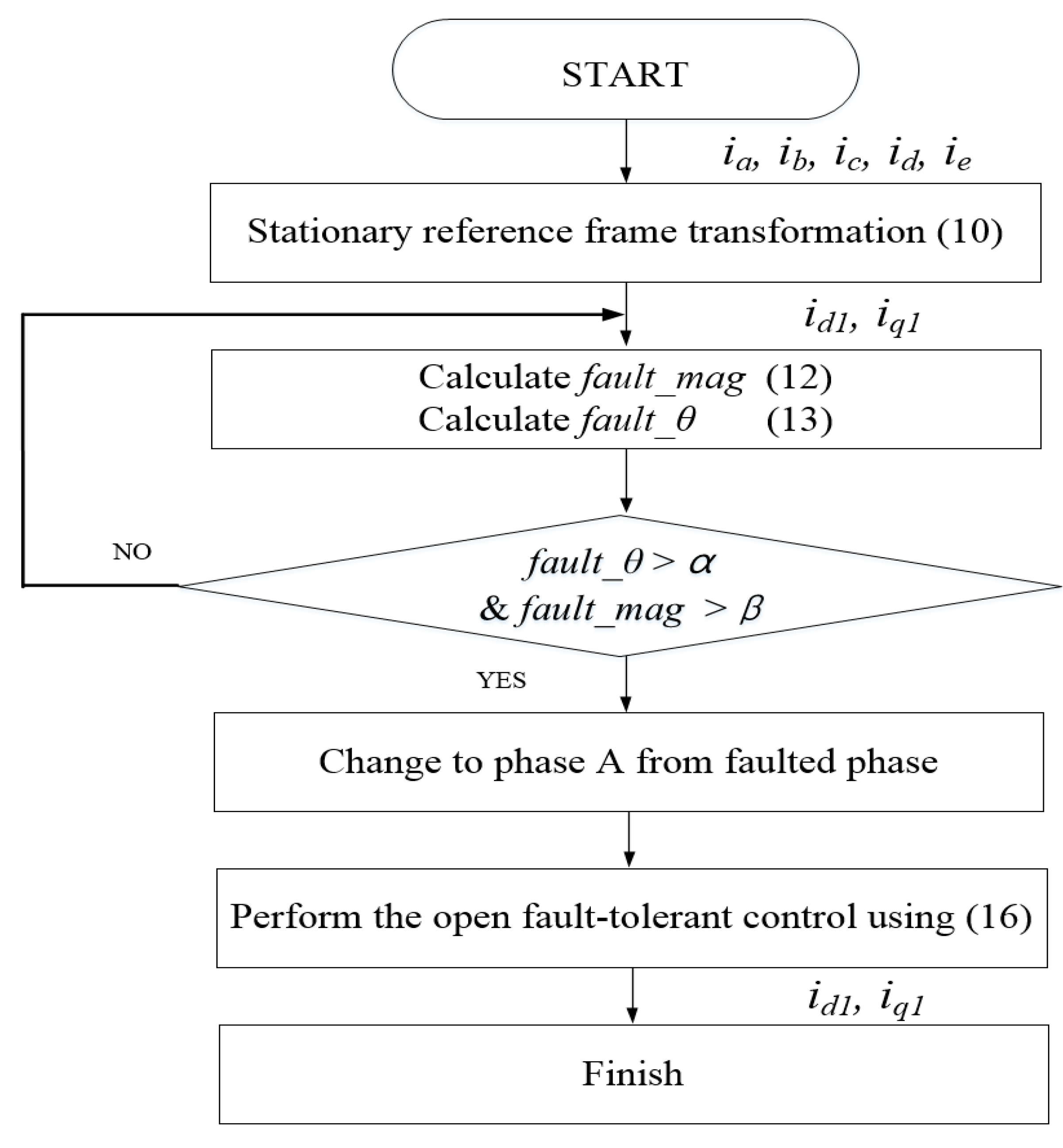
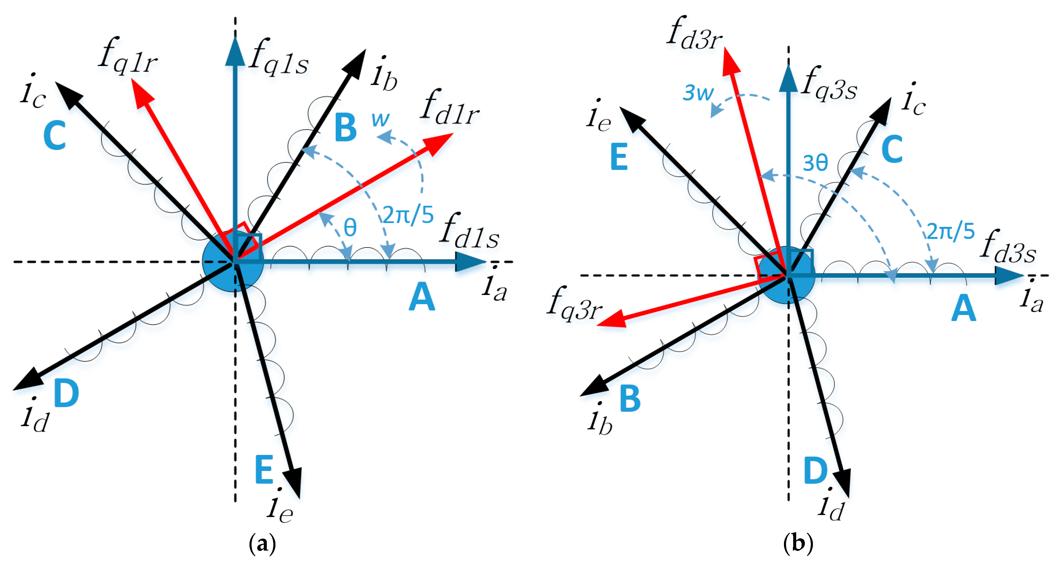
2. Proposed Fault Detection Method

This paper uses a four-pole five-phase IM with identical quasi-concentrated phase windings, which are evenly distributed with a 72° spatial angle as shown in Figure 1. An open fault type can be divided into two categories: the fault in the one leg of the inverter and the fault in one switch of the machine.
When the open fault occurs in the one switch and one phase, trajectory of stationary frame d-q axis current appears as shown in Figure 2 and Figure 3. These patterns can be used to verify whether the fault occurs or not according to the each switch situation. The result of Figure 2 can be verified in accordance with the speed and current. Although the current is very high, the fault patterns are classified to each phase. In order to detect the open fault, the proposed detection method is used for the five-phase inverter.
The proposed fault detection method uses the d1-q1 axis current from the five-phase transformation matrix. The d1-q1 axis current can be expressed as:
i d 1 s s = 2 5 ( i a cos ( 0 ) + i b cos ( 2 π 5 ) + i c cos ( 4 π 5 ) + i d cos ( 4 π 5 ) + i e cos ( 2 π 5 ) )
i q 1 s s = 2 5 ( i a sin ( 0 ) + i b sin ( 2 π 5 ) + i c sin ( 4 π 5 ) i d sin ( 4 π 5 ) i e sin ( 2 π 5 ) )
where ia, ib, ic, id, and ie are the phase currents. When the five-phase IM is operated in normal mode, x axis and y axis are applied to Equation (1) and (2) as shown in normal operation of Figure 2. At that time, if the open fault of the top switch of phase A occurs in the five-phase inverter, the faulted pattern appears to one side in the trajectory of a stationary frame as shown in Figure 3. As a same result, the faulted patterns of one phase appear to both sides in the trajectory of stationary frame as shown in Figure 2.
Table 1 depicts in the analysis result of an open fault angle for each switch and leg from Figure 2. Because all switches have an angle region of 36°, the flag signal can be considered in from 1 to 10. Therefore, all open fault switches can be recognized in accordance with the information of switch position.
In order to calculate the average d1-q1 axis current during the one cycle, these can be expressed as:
i d 1 s s _ m e a n = k = 0 N u m i d 1 s s [ k ]
i q 1 s s _ m e a n = k = 0 N u m i q 1 s s [ k ]
f a u l t _ m a g = ( i d 1 s s _ m e a n ) 2 + ( i q 1 s s _ m e a n ) 2
where id1ss_mean and iq1ss_mean are mean values of the stationary reference frame d1-q1 axis current during the one cycle. Num is number of arrangement. When the five-phase IM is operating in the normal mode, id1ss and iq1ss are kept at constant sinusoidal waves which have difference of 90°. At this time, the fault_mag remains at zero value, because id1ss_mean and iq1ss_mean are zero under normal operation. However, when an open fault occurs in the switch of the inverter, the fault_mag no longer remains zero. Therefore, in order to detect the fault switch, fault_mag is compared with a predefined threshold value.
It is important to detect the faulty switch position in the open fault case. Using the stationary reference frame, the fault angle and error can be expressed as:
f a u l t _ θ = tan 1 ( i q 1 s s i d 1 s s )
f a u l t _ θ e r r o r = f a u l t _ θ f a u l t _ θ o l d
where fault_θold is the previous fault_θ. When the five-phase IM is operated in the normal mode, fault_θerror has almost constant value. However, when the fault occurs in the one switch of the inverter, fault_θerror changes rapidly. The fault switch can be recognized from the angle of that time. The proposed fault detection method recognizes the open fault of the switch when both conditions of fault_mag and fault_θerror are satisfied.

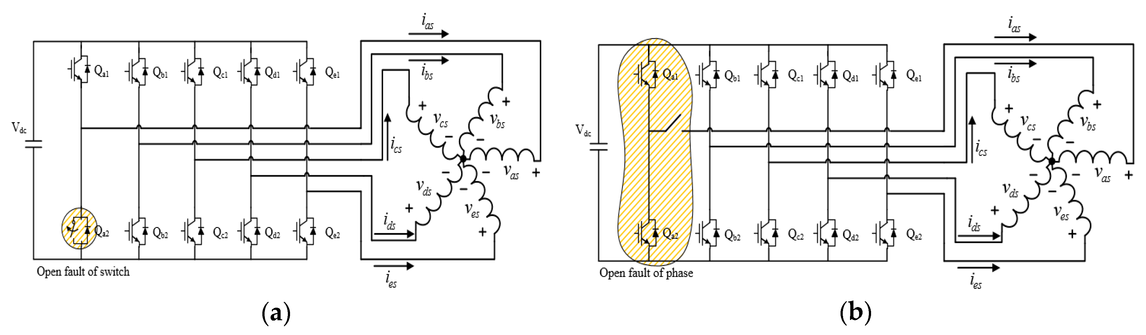
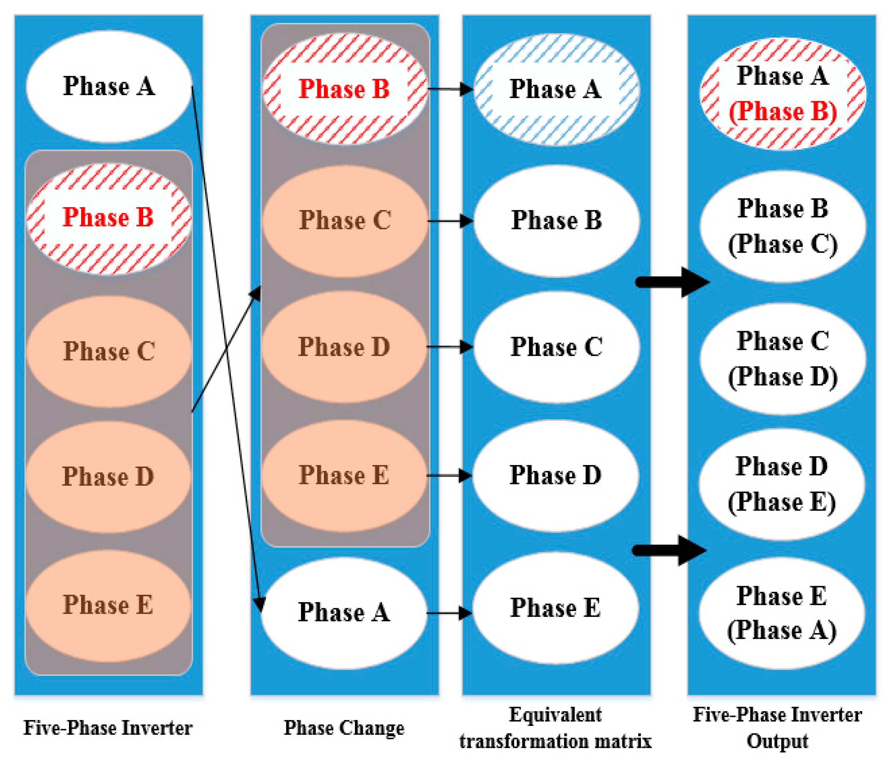
3. Proposed Fault-Tolerant Control Method

The five-phase space vector of IM is extended from three-phase IM. In order to improve the performance of the torque density, the five-phase IM has the rectangular current waveform, because of its spatial current density and the airgap flux density of the concentrated windings. Therefore, it can be applied to two space vector combined fundamental d1-q1 and third harmonic d3-q3 model.
Two space vector of the five-phase IM can be expressed [27]:
f d 1 q 1 s = 2 5 ( f a s + a 5 f b s + a 5 2 f c s + a 5 3 f d s + a 5 4 f e s ) = f d 1 s + j f q 1 s
f d 3 q 3 s = 2 5 ( f a s + a 5 f c s + a 5 2 f e s + a 5 3 f b s + a 5 4 f d s ) = f d 3 s + j f q 3 s
where a 5 = e j 2 π / 5 .
From Equations (8) and (9), orthogonal matrix for the equivalent transformation of five-phase IM including fundamental d1-q1 axis and third harmonic d3-q3 axis is defined as follows:
T ( θ ) = 2 5 [ cos θ cos ( θ 2 π 5 ) cos ( θ 4 π 5 ) cos ( θ + 4 π 5 ) cos ( θ + 2 π 5 ) sin θ sin ( θ 2 π 5 ) sin ( θ 4 π 5 ) sin ( θ + 4 π 5 ) sin ( θ + 2 π 5 ) cos 3 θ cos 3 ( θ 2 π 5 ) cos 3 ( θ 4 π 5 ) cos 3 ( θ + 4 π 5 ) cos 3 ( θ + 2 π 5 ) sin 3 θ sin 3 ( θ 2 π 5 ) sin 3 ( θ 4 π 5 ) sin 3 ( θ + 4 π 5 ) sin 3 ( θ + 2 π 5 ) 1 2 1 2 1 2 1 2 1 2 ]
Because of pseudo orthogonal property of Equation (10), inverse transfer matrix can be defined as follows:
T ( θ ) 1 = 5 2 T T ( θ )
The inverse transfer matrix is defined as follow Equation (12):
T ( θ ) 1 = [ cos θ sin θ cos 3 θ sin 3 θ 1 2 cos ( θ 2 π 5 ) sin ( θ 2 π 5 ) cos 3 ( θ 2 π 5 ) sin 3 ( θ 2 π 5 ) 1 2 cos ( θ 4 π 5 ) sin ( θ 4 π 5 ) cos 3 ( θ 4 π 5 ) sin 3 ( θ 4 π 5 ) 1 2 cos ( θ + 4 π 5 ) sin ( θ + 4 π 5 ) cos 3 ( θ + 4 π 5 ) sin 3 ( θ + 4 π 5 ) 1 2 cos ( θ + 2 π 5 ) sin ( θ + 2 π 5 ) cos 3 ( θ + 2 π 5 ) sin 3 ( θ + 2 π 5 ) 1 2 ]
In order to perform the vector control in the normal mode, the orthogonal matrix T(0) and its transpose T(0)−1 are used to transform stator quantities between the phase A-B-C-D-E natural reference frame and the d1-q1-d3-q3-n arbitrary reference frame in the five-phase IM.
From Equations (8) and (9), synchronous frame of space vectors in the d1-q1 and d3-q3 can be defined as follows:
f d 1 q 1 r = f d 1 q 1 s e j θ = f d 1 r + j f q 1 r
f d 3 q 3 r = f d 3 q s e j 3 θ = f d 3 r + j f q 3 r
where θ ( = w d t ) and 3θ are the angular velocity of fundamental and third harmonic frequency. From Equations (13) and (14), Figure 4 shows the relationship between stationary reference frame and synchronous frame of the two space vector d1-q1 axis and d3-q3 axis. Two orthogonal and two-dimensional spaces are rotating with the frequency of w and 3w, respectively.
In order to perform the vector control in the normal mode, the orthogonal matrix and its transpose are used to transform stator quantities between the A-B-C-D-E natural reference frame and the d1-q1-d3-q3-n arbitrary reference frame in the five-phase IM. The pseudo-orthogonal matrix can be expressed as:
T ( 0 ) = 2 5 [ 1 cos α cos 2 α cos 2 α cos α 0 sin α sin 2 α sin 2 α sin α 1 cos 2 α cos α cos α cos 2 α 0 sin 2 α sin α sin α sin 2 α 1 2 1 2 1 2 1 2 1 2 ] ,   α = 2 π 5
The equivalent transformation matrix from the B, C, D, and phase E variables to the stationary d1-q1-q3-n axis variables can be expressed as:
T ( 0 ) = 2 5 [ cos α + 0.25 cos 2 α + 0.25 cos 2 α + 0.25 cos α + 0.25 sin α sin 2 α sin 2 α sin α sin 2 α sin α sin 2 α sin 2 α 1 1 1 1 ]
This fault-tolerant control uses five-phase transformation matrix under the open fault condition of phase A [24]. However, the five-phase drive system has same open fault probabilities in each phase in applications. If the open fault occurs in the five-phase inverter except for phase A, it is difficult to directly use the equivalent transformation matrix of Equation (16). When the open fault occurs in the power switch of the phase B, the proposed fault-tolerant control can be used in this system.
To solve this problem of any switch fault rather than phase A, this paper proposes an algorithm that can be applied the open fault of any other fault-tolerant control of five-phase AC motor drive phases as shown in Figure 5. For example, if the open fault occurs in the phase B of the five-phase inverter, the faulted phase B is changed to phase A. After that, Equation (16) can be applied to perform the fault-tolerant control. Finally, the phase A changes to phase E and phase B changes to phase A such as the right side of Figure 5. In the same manner, entire phases can be changed using the proposed algorithm.
Figure 6 shows the flow chart for fault detection and fault-tolerant control. The proposed fault detection method and fault-tolerant control are performed as shown in Figure 6. Aforementioned, when the five-phase IM is operated in normal mode, the vector control is used in the five-phase inverter. At that time, when the open fault occurs in the switch of the phase B, the position of the faulted switch can be detected as shown in Figure 6. In addition, in order to perform the proposed fault-tolerant control, the phase B changes to phase A due to faulted phase B. After that, equivalent transformation matrix Equation (16) is applied to the open fault-tolerant control.
In this paper, the fault-tolerant control is used to minimize copper loss under the one fault condition [24]. From the voltage equation of the five-phase IM, the torque equation can be expressed as Equation (17) in a synchronous frame:
T e = P 2 [ L m 1 ( i q 1 s i d 1 r i d 1 s i q 1 r ) + 3 L m 3 ( i q 3 s i d 3 r i d 3 s i q 3 r ) ]
Under the open fault-tolerant control, the equivalent transformation matrix does not consider id3s axis current from Equation (16). In addition, Equation (17) can be re-written in the following torque equation:
T e = P 2 [ L m 1 ( i q 1 s i d 1 r i d 1 s i q 1 r ) + 3 L m 3 i q 3 s i d 3 r ]
From Equation (18), torque value is positively influenced with synchronous frame current iq3s, however iq3s is negatively influenced with its copper loss.

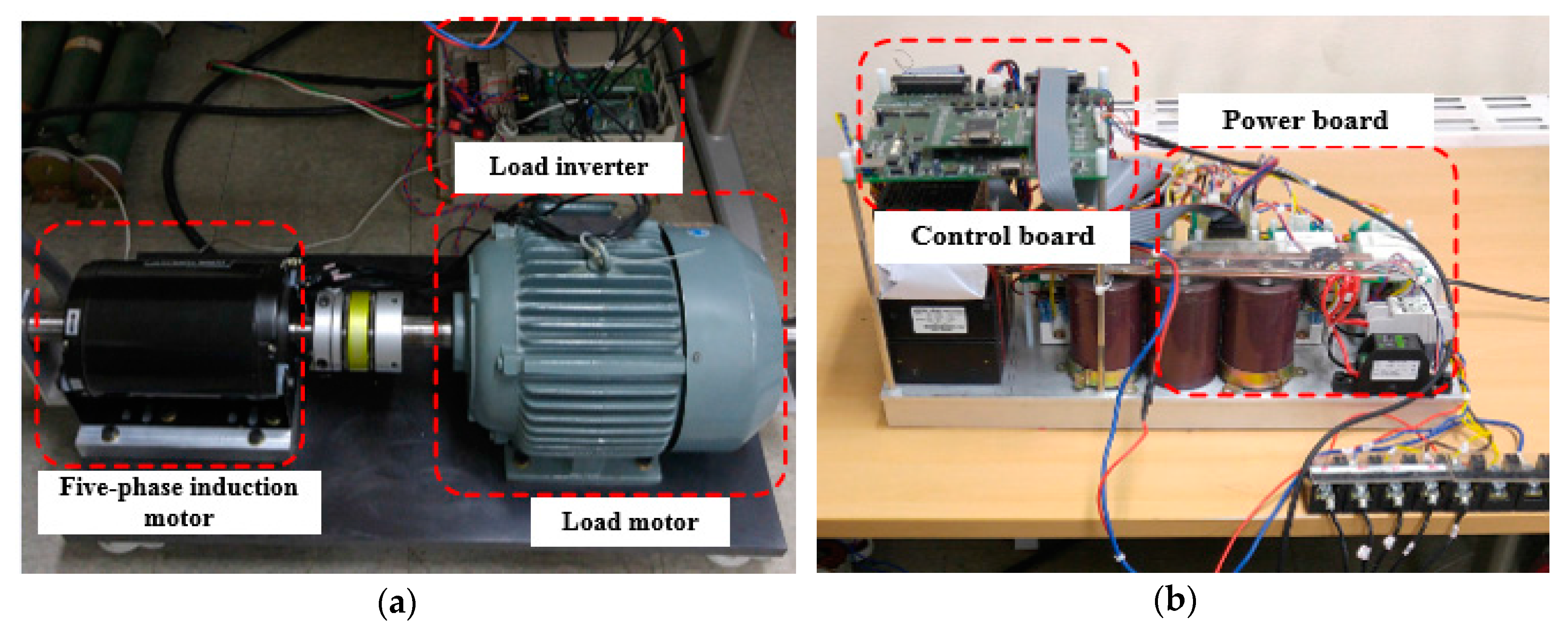
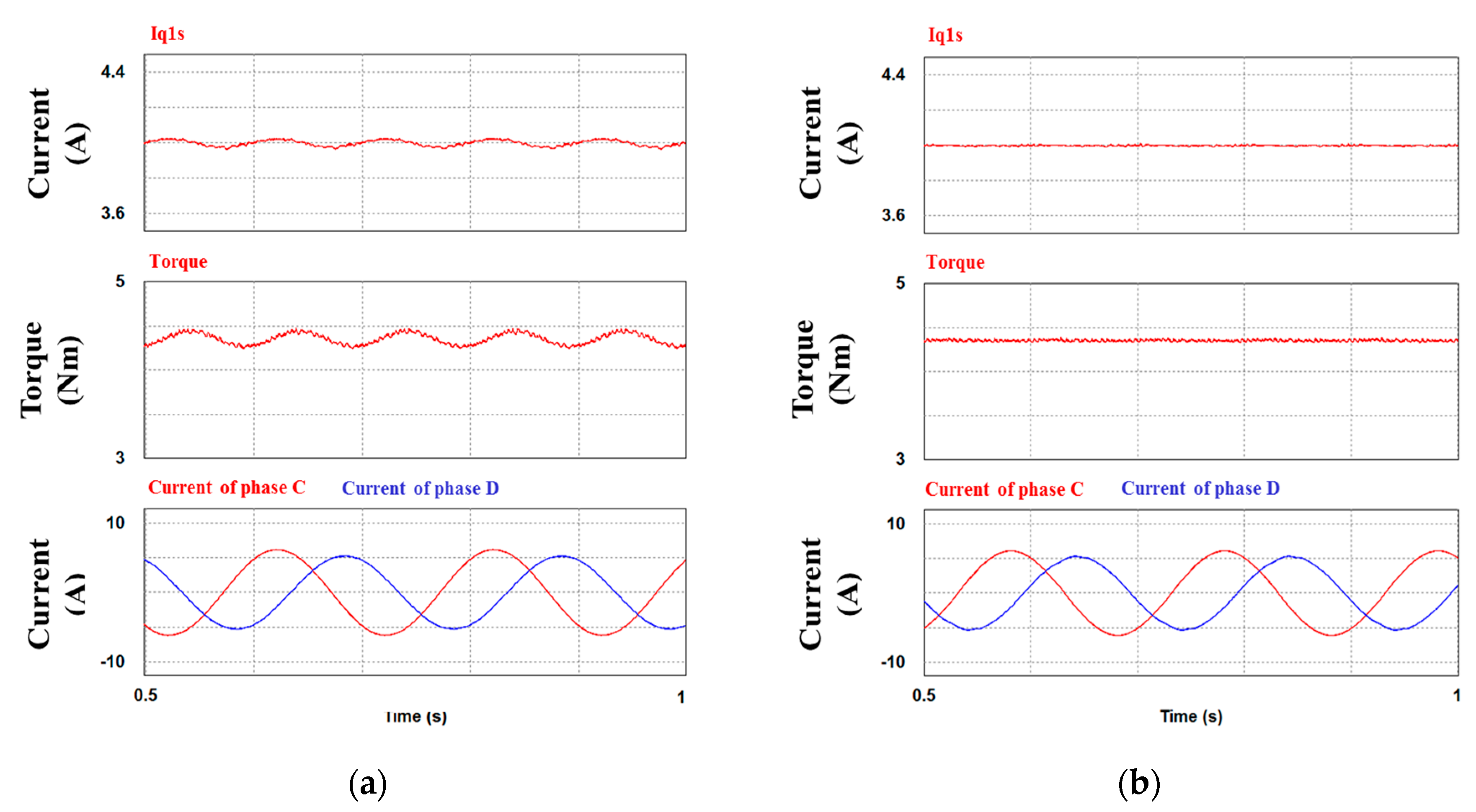
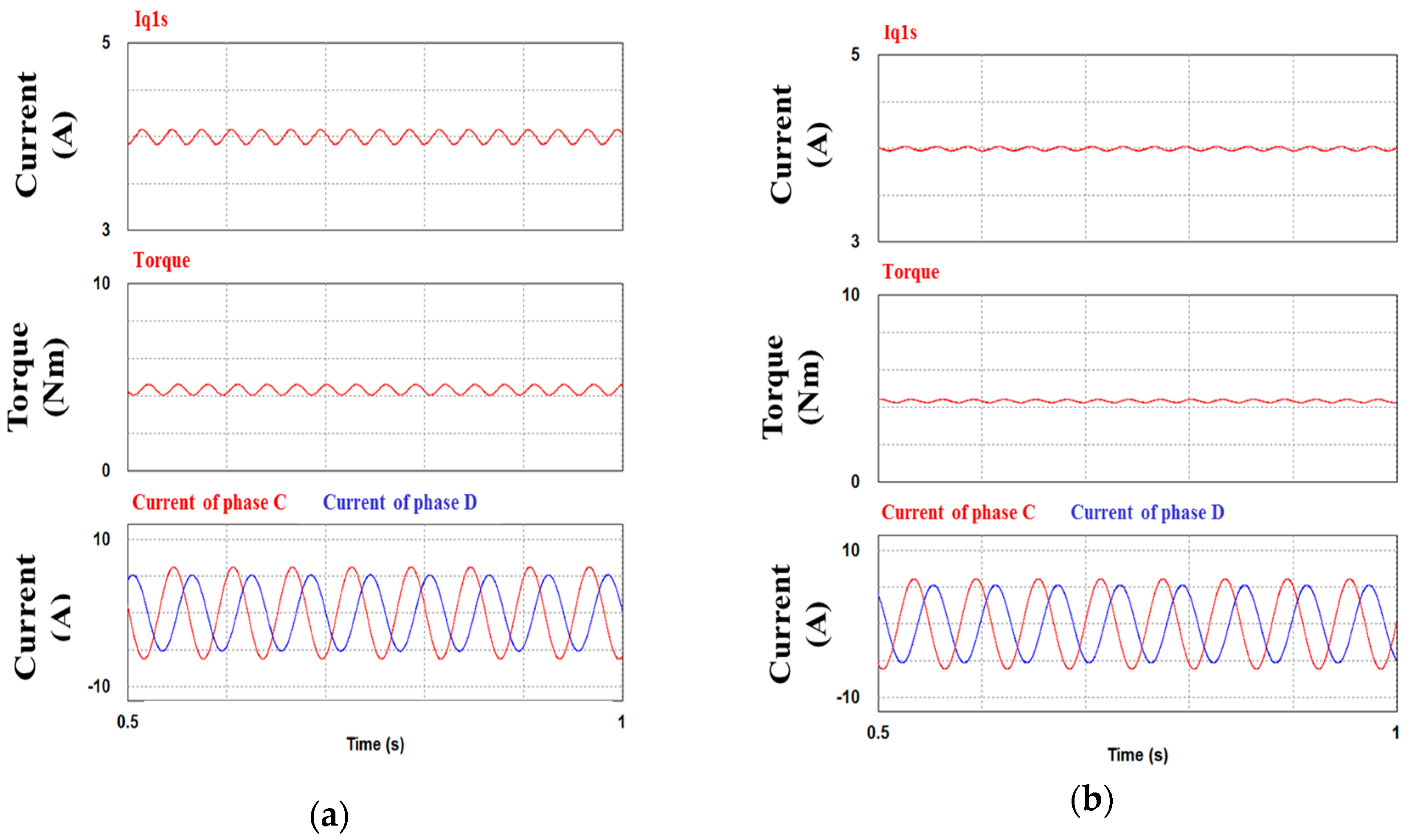
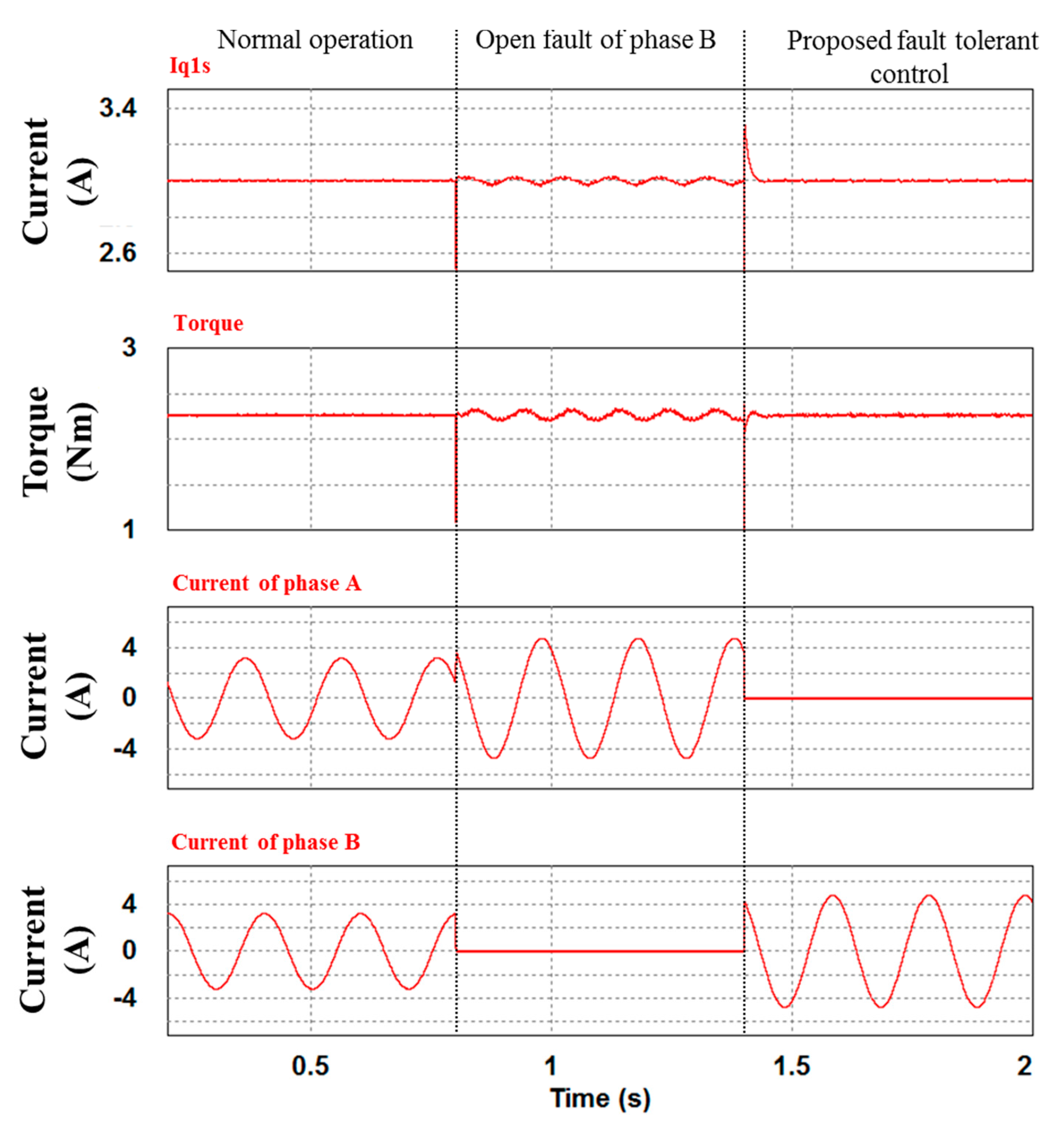
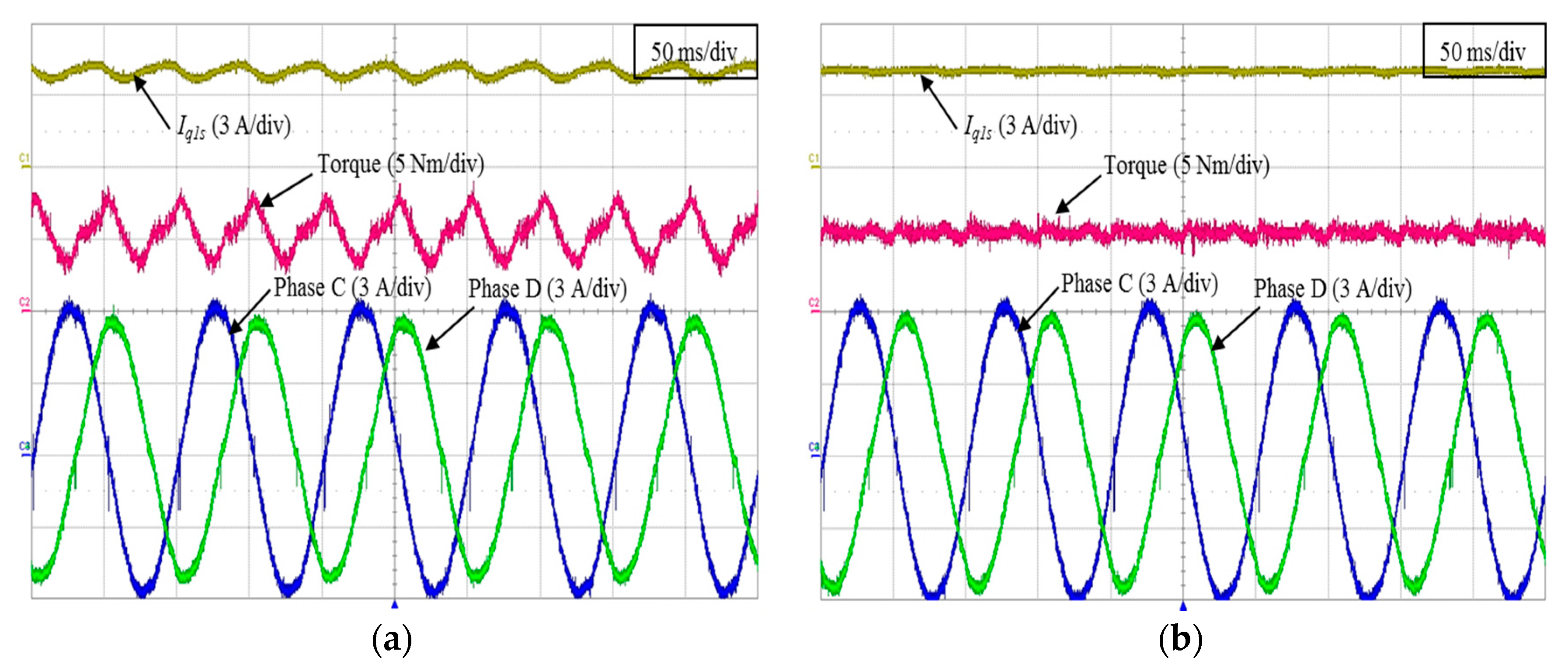
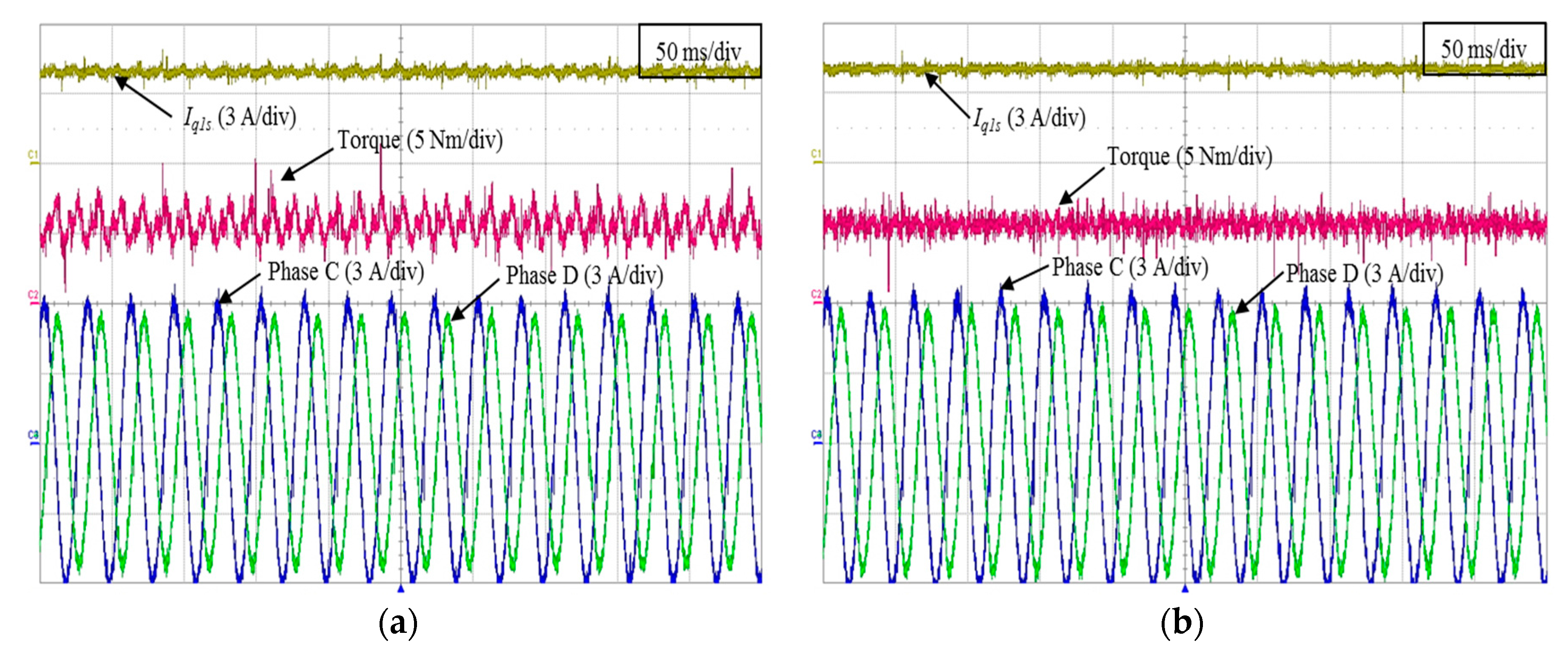
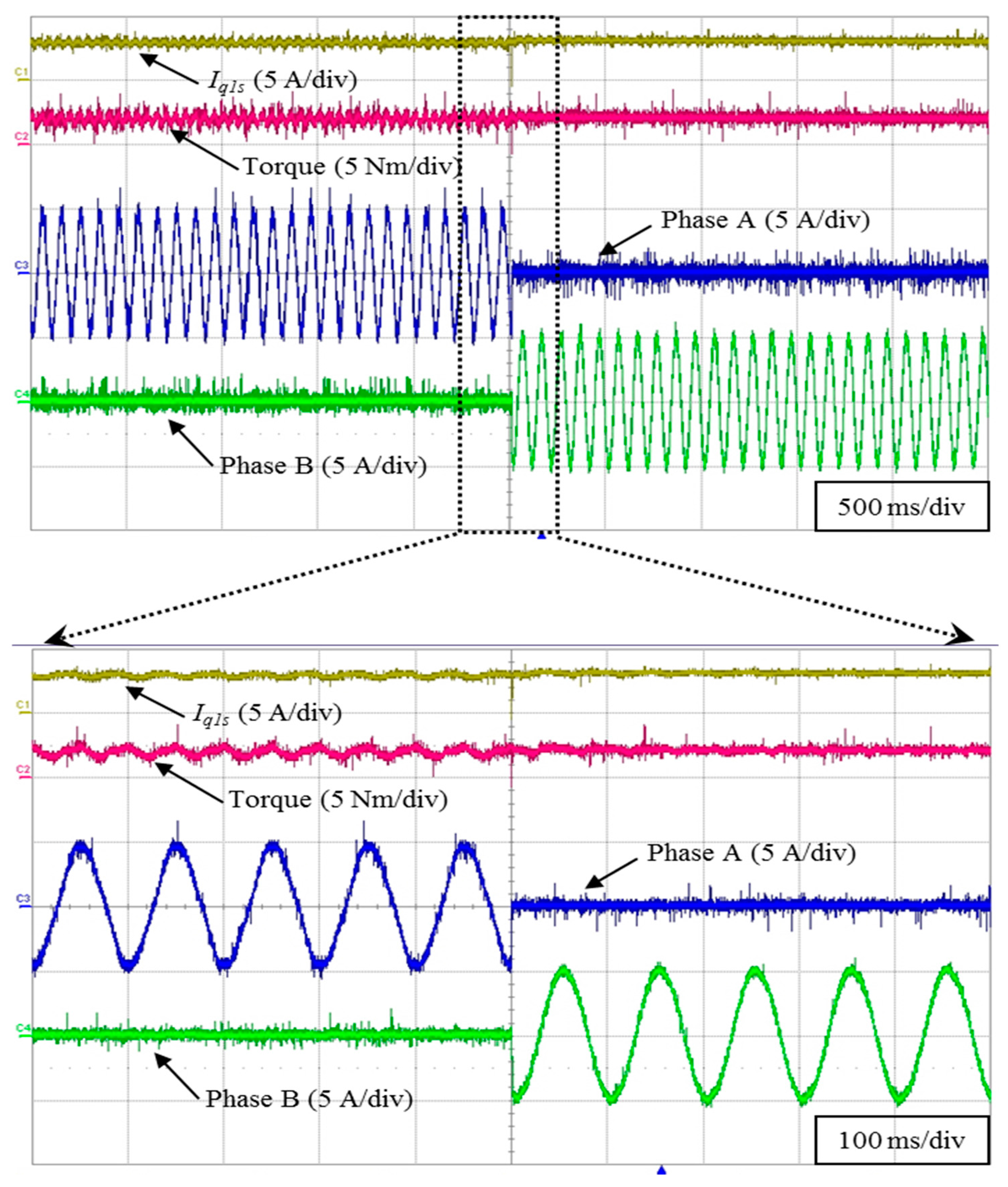
4. Simulation and Experiment Result

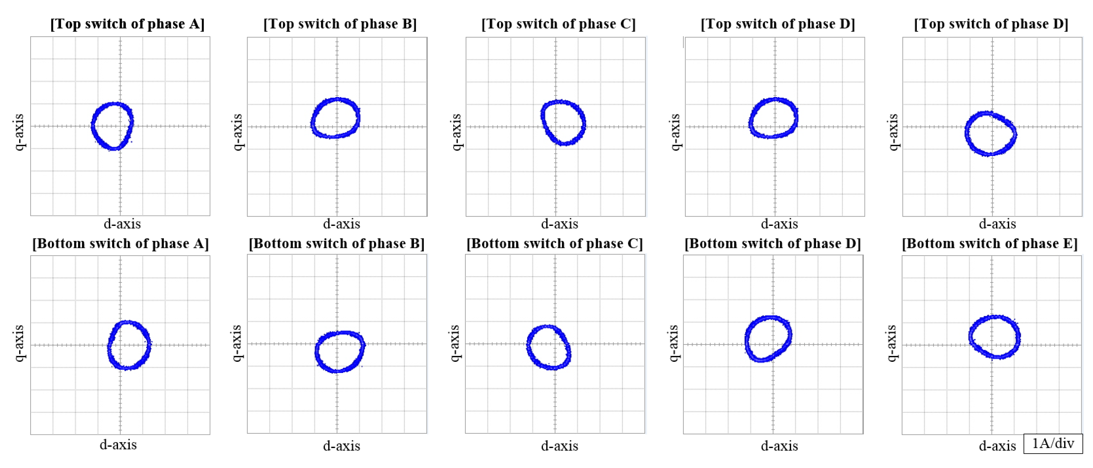
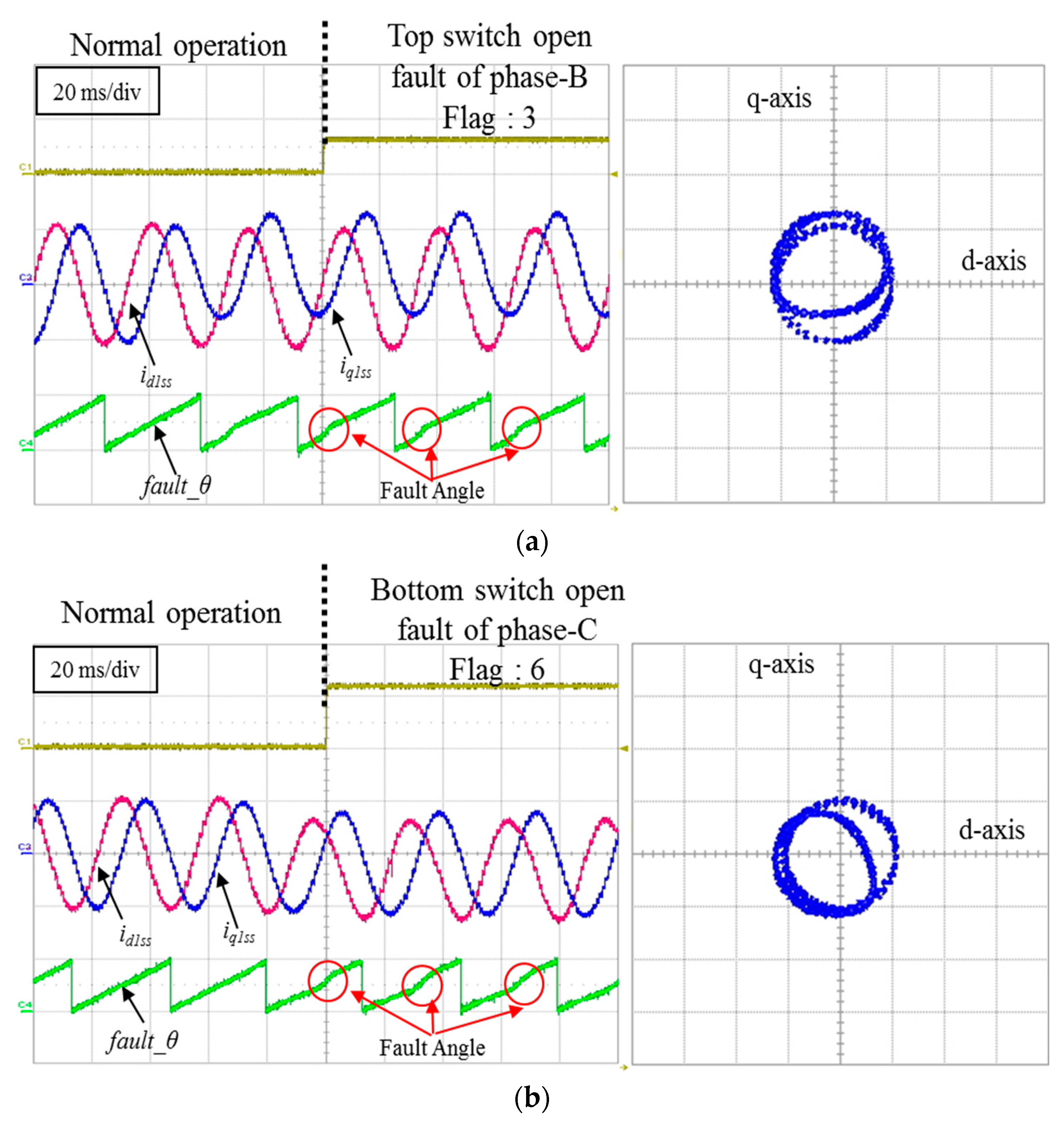
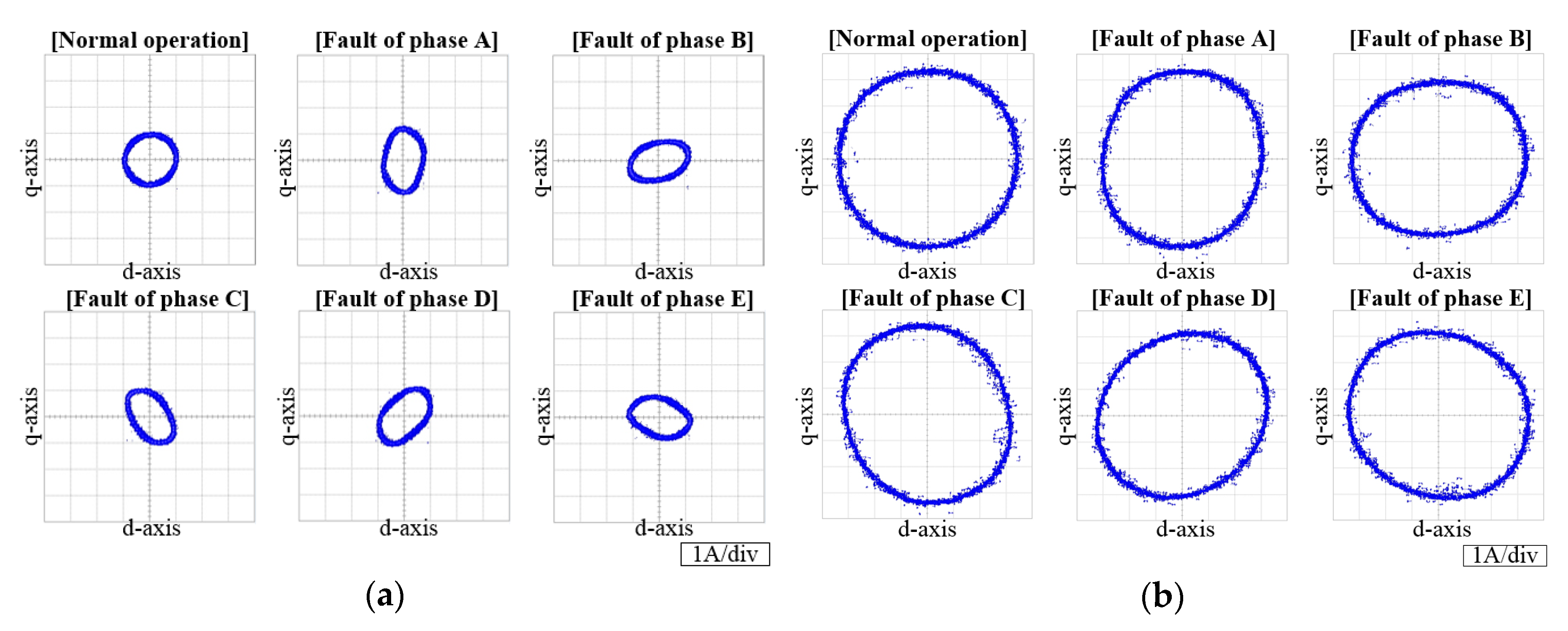
4.1. The Proposed Fault Detection Result

Simulation and experiment results have been carried out for the open fault detection and fault- tolerant control algorithm. Simulation results are obtained using PSIM software tool. Specification of the five-phase IM for the simulation and experiment is listed in Table 2.
Figure 7 shows the experiment set-up of the five-phase IM. Figure 7a shows the MG-set with the five-phase IM. The MG-set consists of a load motor (3.75 kW), inverter, and the five-phase IM. DSP controller TMS320F 28335 from Texas Instruments is used for digital implementation of the proposed techniques. The sampling time of the digital controller in the experimental setup is set to 100 μs.
Figure 8 shows the experimental result of the proposed fault detection method under top switch of the open fault in the phase B and phase C. When the IM is operating in normal mode, the fault_mag is zero in accordance with Equation (5), because the stationary d1-q1 axis current is constant in the steady state condition. In addition, the stationary d1-q1 axis current is used for the fault patterns of each switches. The patterns of the switch can be compared with the patterns of Figure 3 in the trajectory of stationary frame. At that time, when the open fault occurs in the top switch of the phase B, the current of d1-q1 axis changes as shown in Figure 8a. Because the fault_mag is produced by the change of d1-q1 axis under the open fault condition, the fault magnitude exceeds the threshold which can be set in accordance with the applications of the IM. In addition, the patterns of the faulted switch can be verified in comparison with the Figure 3 in the trajectory of the stationary frame. If the proposed fault detection method is applied to other applications of the IM, the threshold can be changed depending upon their situation.
Figure 9 shows the experimental result of fault detection method about fault_θ. When the IM operates in the normal mode, fault_θ of the IM is linear as shown in Figure 9a. As mentioned above, each pattern appeared in the trajectory of the stationary frame. Therefore, the analyzed fault patterns can be used for a fault diagnosis. At that time, when the open fault occurs in the top switch of the phase B, fault_θ changes rapidly in accordance with Equation (6) under the open fault condition, because the id1ss and iq1ss are changed by the top switch of the fault. In addition, each flag is produced by the position information of Table 1. If these two conditions of the angle and magnitude are satisfied, the open fault switch is recognized.

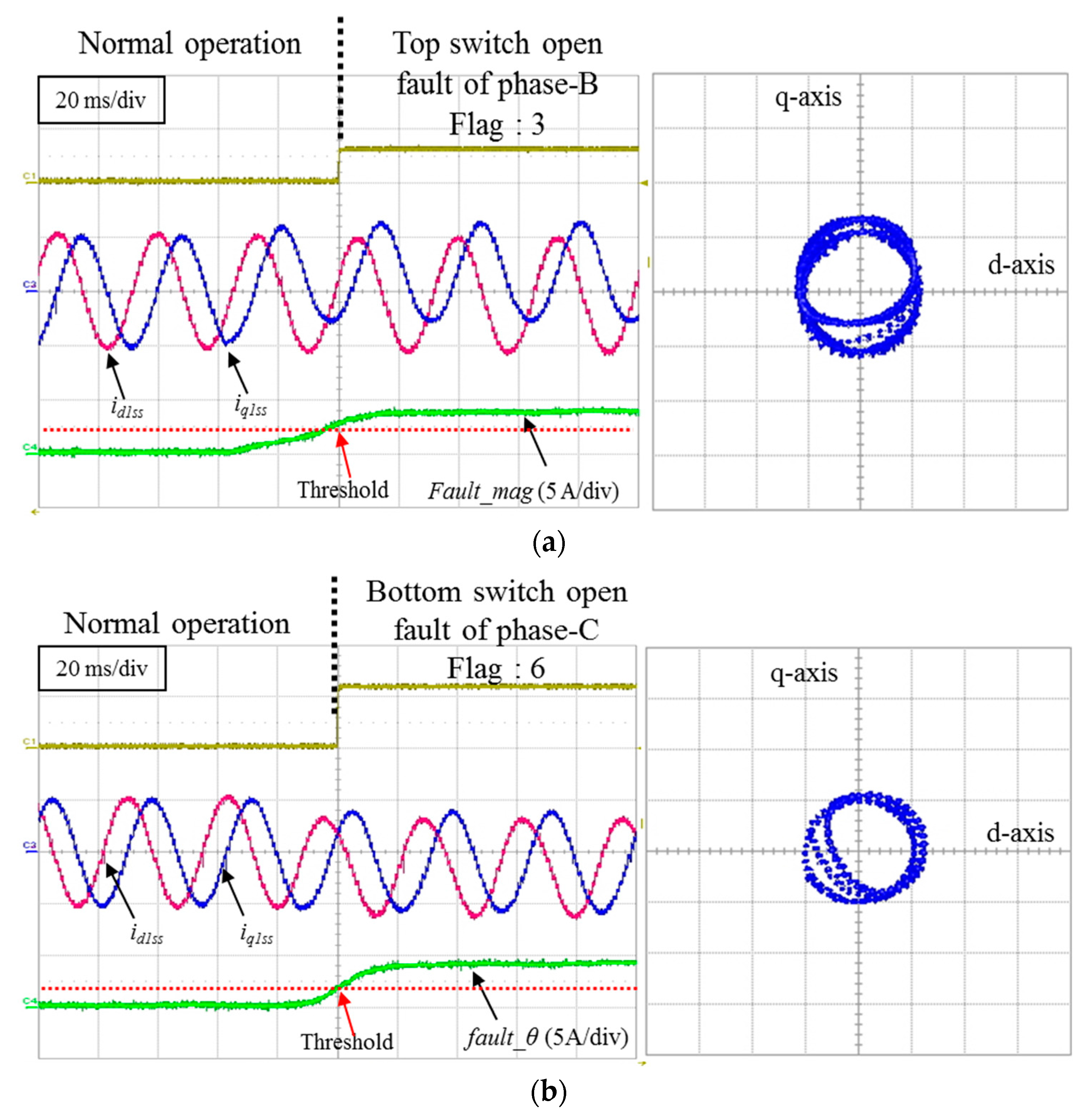
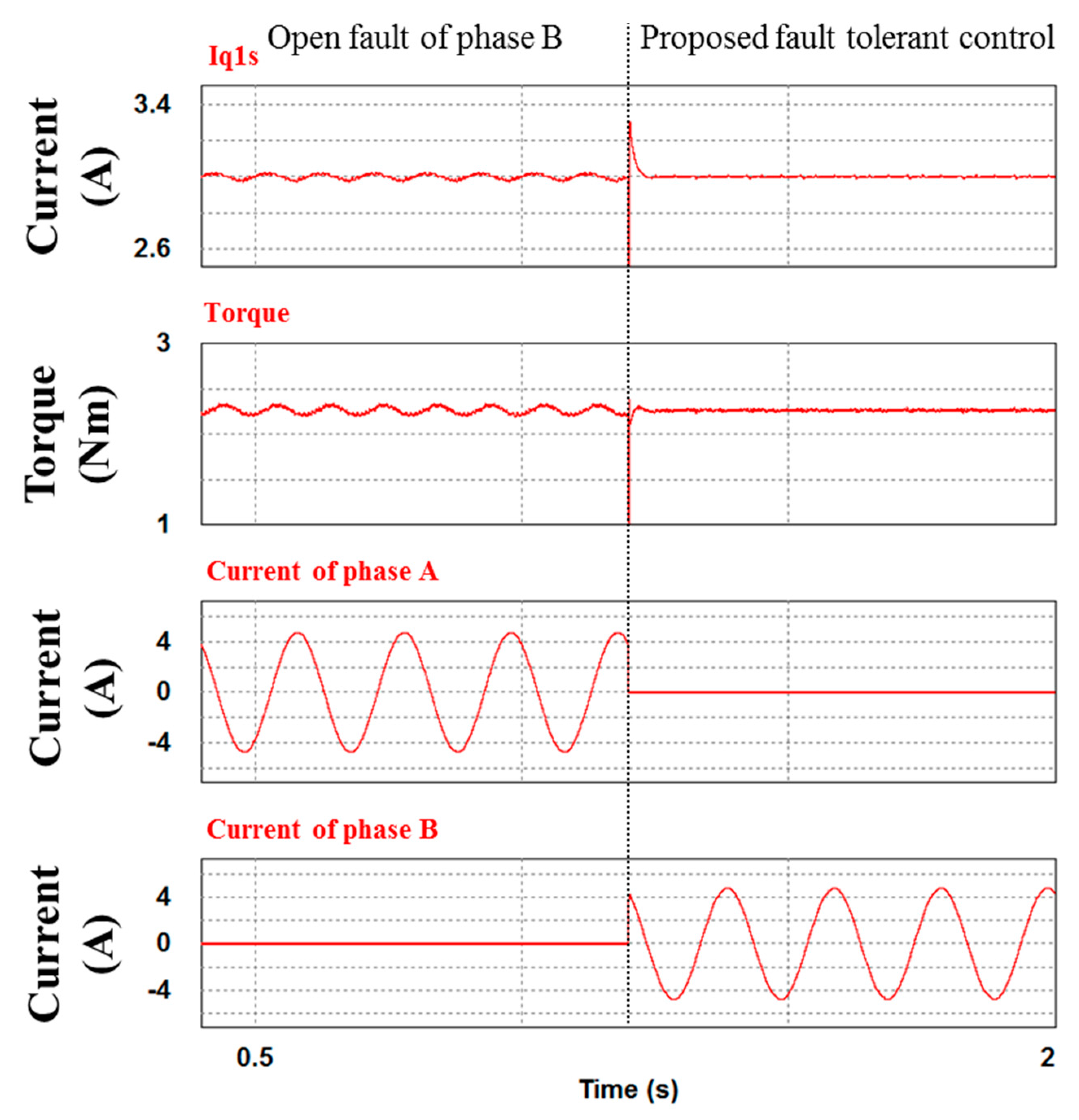
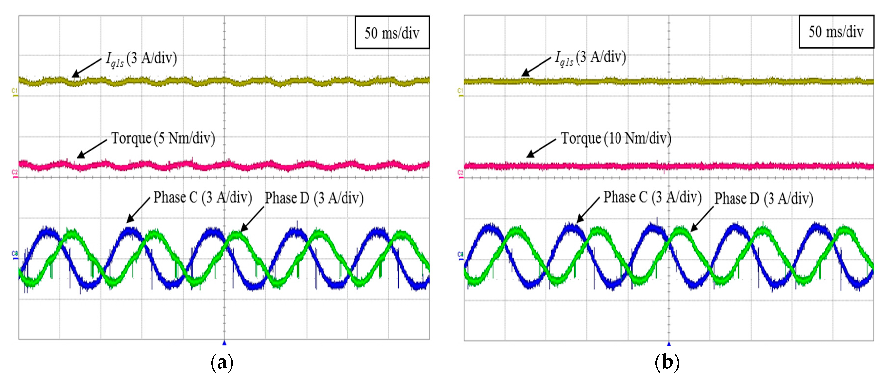
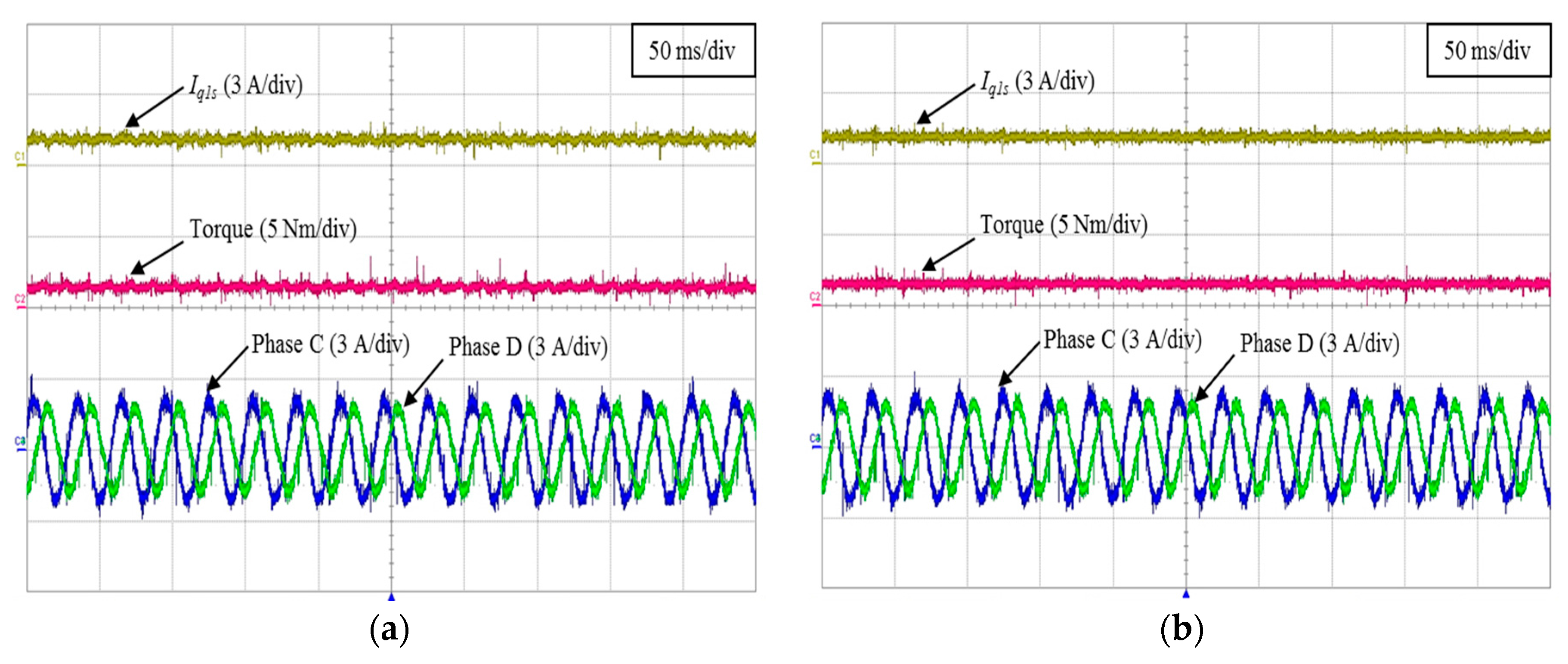
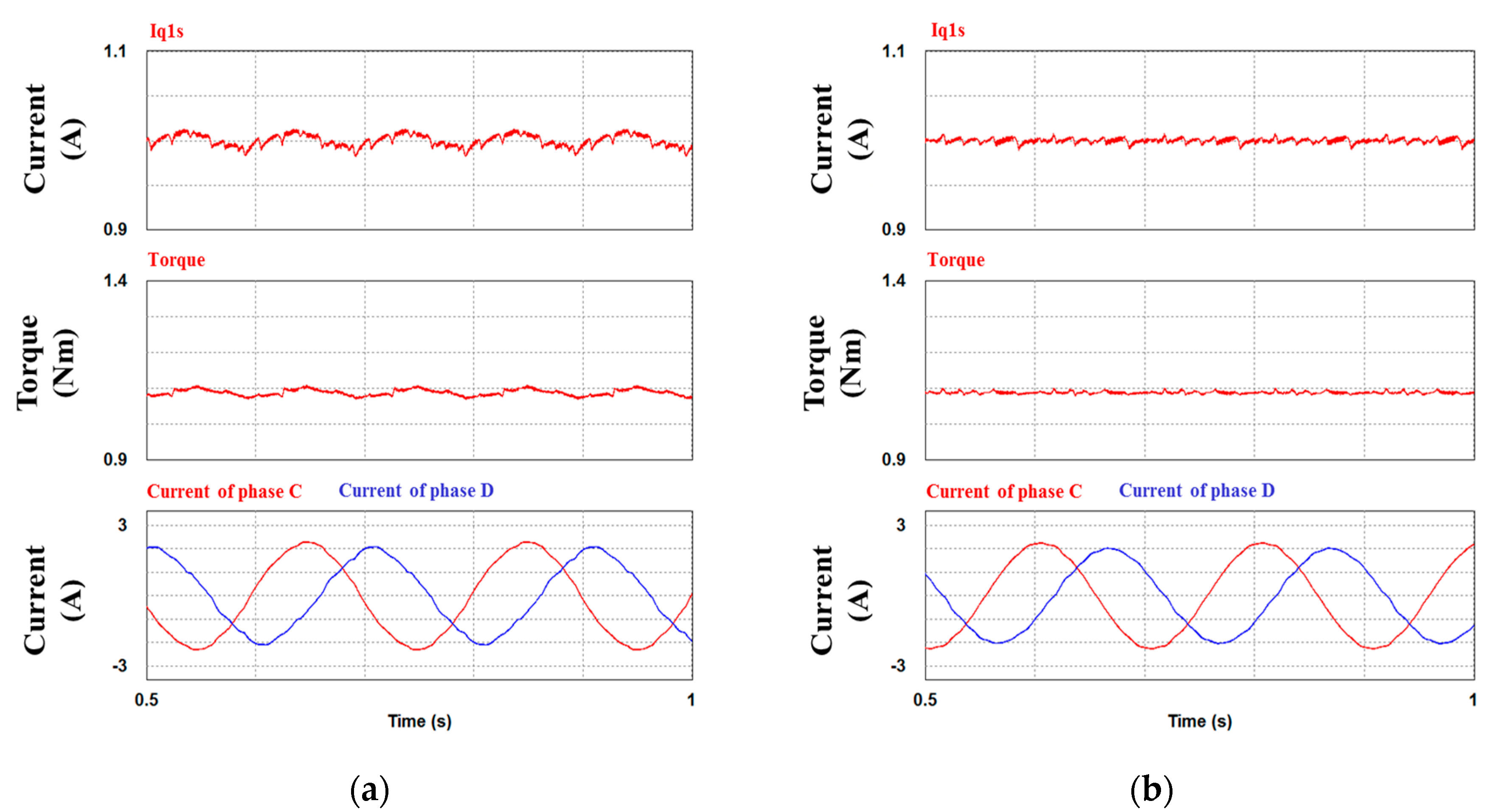
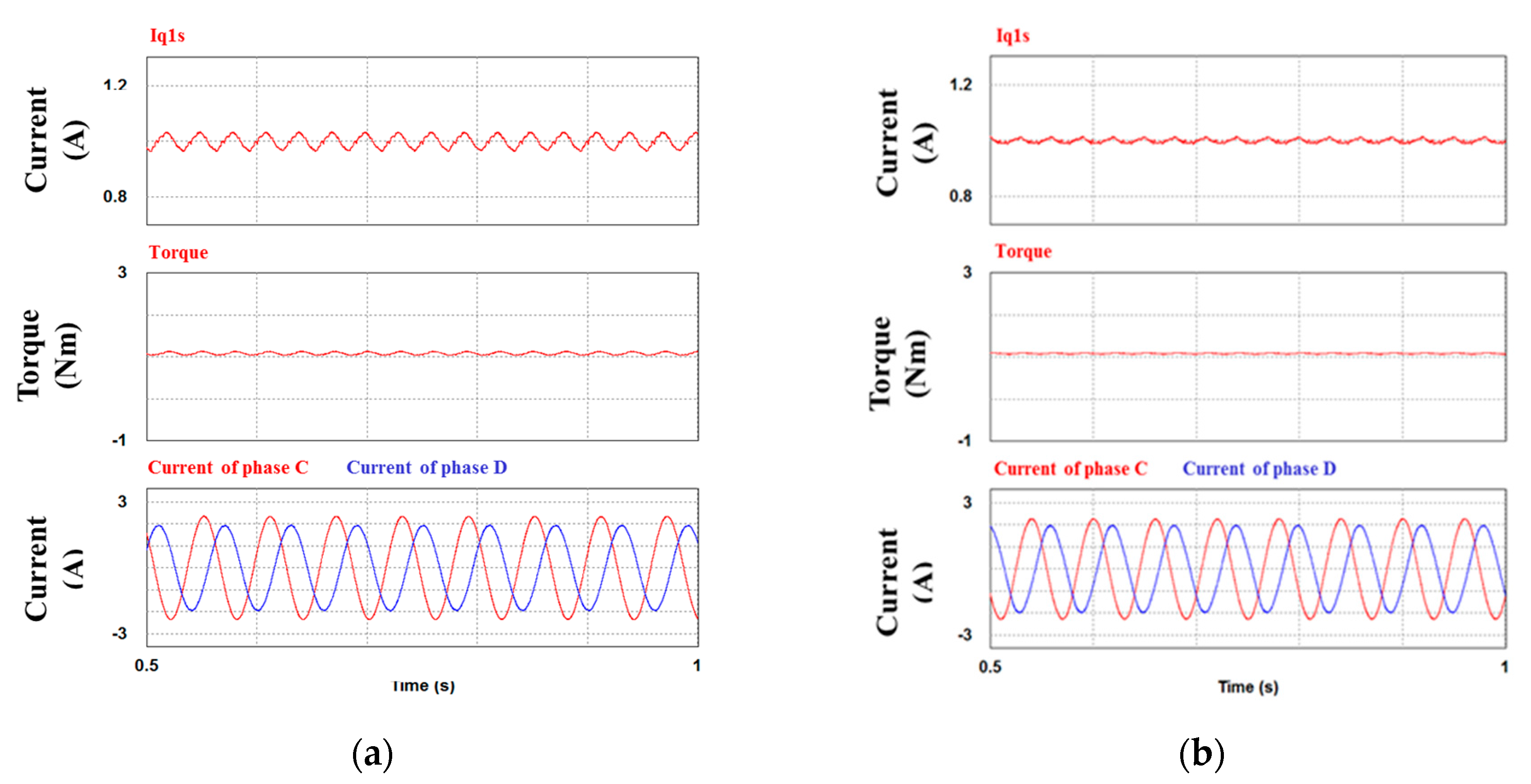
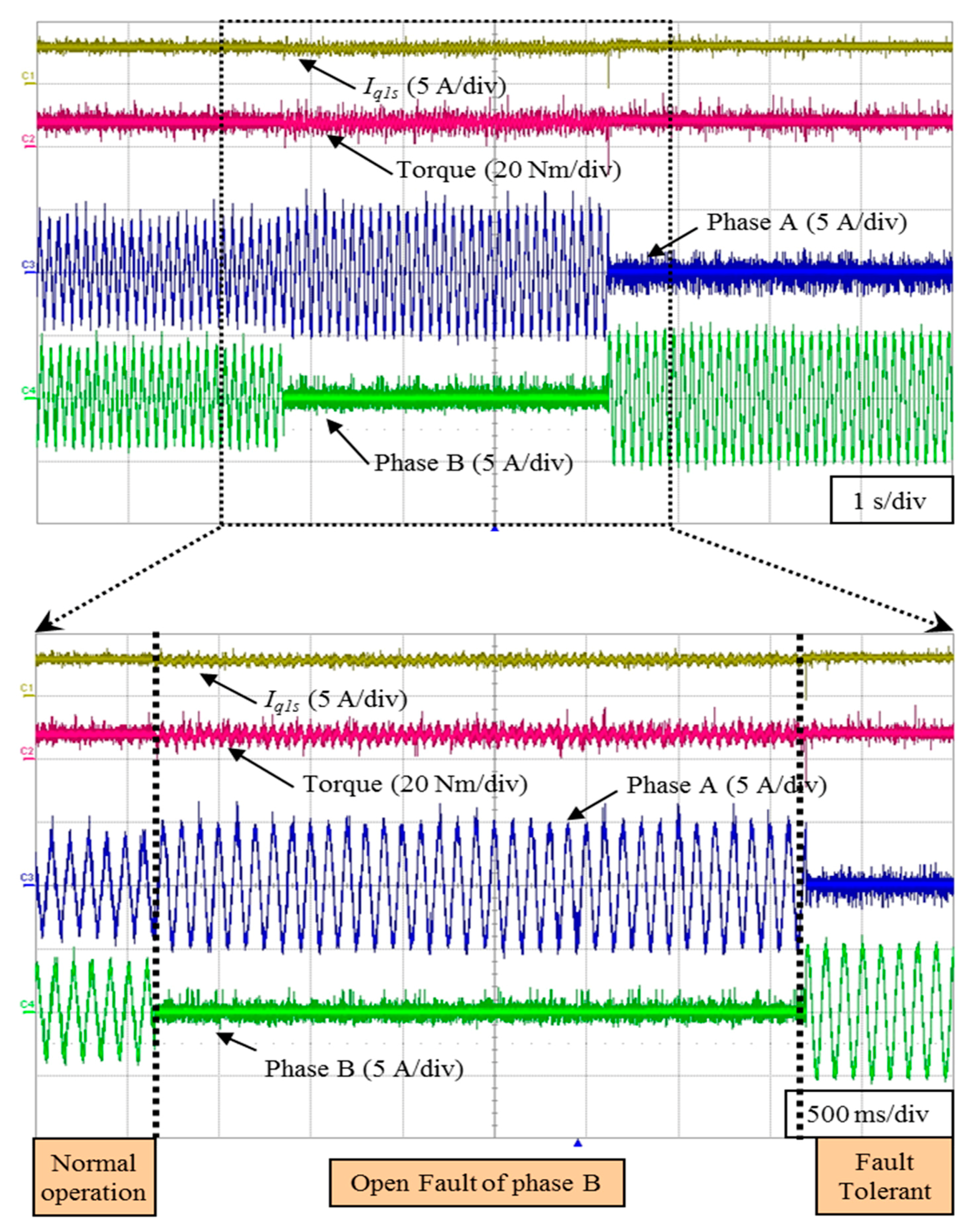
4.2. The Proposed Fault-Tolerant Control Result

Figure 10 shows the simulation result of the fault-tolerant control method under the open fault condition of phase B. Synchronous frame q1 axis current and motor speed are commanded to be 1 A and 300 rpm respectively. Figure 10a does not use fault-tolerant control. In addition, Figure 10a has a ripple about the q1 axis current and the torque in accordance with frequency of speed. However, Figure 10b is applied proposed fault-tolerant control algorithm in accordance with Equation (16) and Figure 5. The synchronous frame q1 axis is current and the torque is regulated without steady state error as shown in Figure 10b.
In order to verify the fault-tolerant control under the other condition, Figure 11 shows the simulation result in the iq1s = 4 A of the synchronous frame. Because of the increase of iq1s, the torque is changed to 4.4 Nm. When the Figure 11a is compared with Figure 11b, the torque ripple of Figure 11a is increased more than Figure 11b.
When the current reference is same as 1 A, the fault-tolerant control is performed to the high speed as shown in Figure 12. Simulation result of the fault-tolerant control has good performance compared with no fault-tolerant control. The torque ripple of Figure 12b is not almost influenced with IM speed changes under the open fault of phase B.
Figure 13 shows the simulation result of the fault-tolerant control at high torque and high speed. The difference of no fault-tolerant control and fault-tolerant control is obvious from Figure 13a. The proposed fault-tolerant algorithm of Figure 13b shows good performance compared with Figure 13a. Specially, the torque ripple is reduced over 50% compared with no fault-tolerant control.
The left side of Figure 14 shows the open fault condition when the open fault occurs in the switch of phase B. Synchronous frame q1 axis current and motor speed are commanded to be 3 A and 300 rpm respectively. There are torque ripples due to no fault-tolerant control. After one second, the proposed fault-tolerant control is applied. Then the fault phase B is replaced with phase A as shown in Figure 14. The torque and current ripple are decreased, when the proposed fault-tolerant algorithm is applied.
Figure 15 shows result of operation sequence of the fault-tolerant control under the open fault of phase B. When the five-phase IM is operated in normal mode, the current is controlled in accordance with the current reference. At that time, if the open fault occurs in phase B, the current and torque ripple are produced by the open fault. However, after the fault-tolerant control is applied, phase A and phase B changed well without decreasing the IM speed. In addition, the current and torque ripple are regulated well. It is obvious that the fault-tolerant algorithm has good performance under one phase fault conditions. The proposed algorithm has almost the same current and torque ripple compared with normal operation conditions. To verify the feasibility of the fault-tolerant control, Figure 16 shows difference under the open fault condition of phase B in iq1s = 1 A and 300 rpm. Figure 16a has the current at the q1 axis current and the torque in accordance with frequency of speed. However, Figure 16b is applied to the proposed fault-tolerant control algorithm in accordance with Equation (16).
In Figure 17, the synchronous frame q1 axis current and motor speed are commanded to be 4 A and 300 rpm, respectively. According to the increase of the q1 axis current, the torque is changed to 5 Nm. When the fault-tolerant algorithm is not used, the torque ripple fluctuates to 5 Nm. However, when the fault-tolerant algorithm is used, torque ripple reduces to 1.5 Nm. From Figure 16 to Figure 17, it is obvious that the proposed algorithm can regulate the ripple of the q1 axis current and torque.
To verify the ripple of the current and torque at the high speed, the fault-tolerant control is performed at 1000 rpm as shown in Figure 18. When the fault-tolerant control is not used, the torque ripple is similar with the result of the low speed operation. Because the reference of the q1 axis current is 1 A, the torque has a low torque ripple. However, when the fault-tolerant control is used, the ripple of the current and torque no longer exists.
In Figure 19, the synchronous frame q1 axis current and motor speed are controlled to high torque and high speed. The ripple of the current and torque is not varied depending on the speed. It is obvious that the torque ripple magnitude has been mainly influenced with magnitude of q1 axis current.
Figure 20 shows the open fault of the phase B and the proposed fault-tolerant control. The synchronous frame q1 axis current and motor speed are commanded to be 3 A and 300 rpm respectively. After four healthy phases operate under the open fault of phase B, the proposed fault-tolerant control is applied. Then the fault phase B is replaced with phase A as shown in Figure 20. At that time, the ripple of the current and torque is decreased.
Figure 21 shows operation sequences that are normal operations, open fault of phase B and tolerant control from left side. When the open fault occurs in phase B, the current magnitude of phase A is increased and the torque ripple is produced by the open fault. However, during the fault-tolerant control application, phase A and phase B changed well without IM speed decreasing. In addition, the current and torque ripple are regulated well, similar to the simulation result. It is obvious that the fault-tolerance algorithm has good performance under one phase fault condition.

5. Conclusions

This paper deals with the fault detection method and fault-tolerant control scheme for five-phase IM. The fault patterns are analyzed for the position information of each switch in the five-phase inverter. The fault detection method is proposed in accordance with the analyzed fault patterns of the switch position. In addition, this method can verify the information in both the faulted phase and switch position during the one cycle. The fault-tolerant control is performed by all phases. The proposed fault-tolerant algorithm contributes to reducing the torque and current ripple at any phase open fault condition. In addition, this algorithm is verified using four healthy phase currents in the open fault condition. The proposed algorithm has been described by using a five-phase IM with one open phase as a practical example and its validity has been proven through the experiments using an 1.5 kW five-phase IM.

Acknowledgments

This research was supported in part by the Human Resources Development program (No. 20134030200310) of the Korea Institute of Energy Technology Evaluation and Planning (KETEP) grant funded by the Korea government Ministry of Trade, Industry and Energy and in part by a grant (No. 15RTRP-B067706-03) from Railroad Technology Research Program funded by Ministry of Land, Infrastructure and Transport of Korean government.

Author Contributions

Kyo-Beum Lee provided guidance and supervision. Choon-Soo Park conceived the idea of this paper. Hye-Ung Shin and Seong-Yun Kang performed the simulation and experiment. Seung-Koo Baek implemented the main research, performed the experiment, wrote the paper, and revised the manuscript as well. All authors have equally contributed to the simulation analysis, experiment, and result discussions.

Conflicts of Interest

The authors declare no conflict of interest.

References

  1. Toliyat, H.A.; Lipo, T.A.; White, J.C. Analysis of a Concentrated Winding Induction Machine for Adjustable Speed Drive Applications Part II: Motor Design and Performance. IEEE Trans. Energy Convers. 1991, 6, 684–692. [Google Scholar] [CrossRef]
  2. Parsa, L.; Toliyat, H.A.; Goodarzi, A. Five-Phase Interior Permanent-Magnet Motors with Low Torque Pulsation. IEEE Trans. Ind. Appl. 2007, 43, 40–46. [Google Scholar] [CrossRef]
  3. Levi, E. Multiphase Electric Machines for Variable-Speed Applications. IEEE Trans. Ind. Electron. 2008, 55, 1893–1909. [Google Scholar] [CrossRef]
  4. Levi, R.; Bojoi, F.; Profumo, F.; Toliyat, H.; Williamson, S. Multiphase Induction Motor Drives—A Technology Status Review. IET Electr. Power Appl. 2007, 1, 489–516. [Google Scholar] [CrossRef]
  5. Wang, J.; Atallah, K.; Howe, D. Optimal torque control of fault-tolerant permanent magnet brushless machines. IEEE Trans. Magn. 2003, 39, 2962–2964. [Google Scholar] [CrossRef]
  6. Atallah, K.; Wang, J.; Howe, D. Torque-ripple minimization in modular PMBL machines. IEEE Trans. Ind. Appl. 2003, 39, 1689–1695. [Google Scholar] [CrossRef]
  7. Tani, A.; Mengoni, M.; Zarri, L.; Serra, G.; Casadei, D. Control of Multi–Phase Induction Motors with an Odd Number of Phases under Open–Circuit Phase Faults. IEEE Trans. Power Electron. 2012, 27, 565–577. [Google Scholar] [CrossRef]
  8. Bianchi, N.; Pre, M.D.; Bolognani, S. Design of a Fault-Tolerant IPM Motor for Electric Power Steering. IEEE Trans. Veh. Technol. 2006, 55, 1102–1111. [Google Scholar] [CrossRef]
  9. Dabour, S.M.; Masoud, M.I. Open-Circuit Fault Detection of Five-Phase Voltage Source Inverters. In Proceedings of the 8th IEEE GCC Conference and Exhibition, Muscat, Oman, 1–4 February 2015; pp. 1–6.
  10. Ribeiro, R.L.A.; Jacobina, C.B.; Dasilva, E.R.C.; Lima, A.M.N. Fault Detection of Open-Switch Damage in Voltage-Fed PWM Motor Drive Systems. IEEE Trans. Power Electron. 2003, 18, 587–593. [Google Scholar] [CrossRef]
  11. Kastha, D.; Bose, B.K. Investigation of Fault Modes of Voltage-Fed-Inverter System for Induction Motor Drive. IEEE Trans. Ind. Appl. 1994, 30, 1028–1037. [Google Scholar] [CrossRef]
  12. Mahmoud, G.; Masoud, M.; El-Arabawy, I. Inverter Faults in Variable Voltage Variable Frequency Induction Motor Drive. In Proceedings of the Compatibility in Power Electronics (CPE), Gdansk, Poland, 29 May–1 June 2007; pp. 1–6.
  13. Lee, J.-S.; Lee, K.-B. Open-Circuit Fault Tolerant Control for Outer Switches of Three-Level Rectifiers in Wind Turbine Systems. IEEE Trans. Power Electron. 2016, 31, 3806–3815. [Google Scholar] [CrossRef]
  14. Nandi, S.; Toliyat, H.A. Condition Monitoring and Fault Diagnosis of Electrical Machines—A Review. In Proceedings of the Industry Applications conference (IAS), Phoenix, AZ, USA, 3–7 October 1999; pp. 197–204.
  15. Mendes, A.M.S.; Cardoso, A.J.M. Voltage Source Inverter Fault Diagnosis in Variable Speed Ac Drives, by the Average Current Park’s Vector Approach. In Proceedings of the IEEE International Electric Machines and Drives Conference (IEMDC), Seattle, WA, USA, 9–12 May 1999; pp. 704–706.
  16. Choi, U.-M.; Jeong, H.-G.; Lee, K.-B.; Blaabjerg, F. Method for Detecting an Open-Switch Fault in a Grid-Connected NPC Inverter System. IEEE Trans. Power Electron. 2012, 27, 2726–2739. [Google Scholar] [CrossRef]
  17. Lee, J.-S.; Lee, K.-B. Tolerance Control for Inner Open-Switch Faults of a T-type Three-Level Rectifier. J. Power Electron. 2014, 14, 1157–1165. [Google Scholar] [CrossRef]
  18. Lee, E.S.; Lee, K.-B. Fault-Tolerant Strategy to Control a Reverse Matrix Converter for an Open-Switch Fault in Rectifier Stage. J. Power Electron. 2016, 61, 57–65. [Google Scholar] [CrossRef]
  19. Im, W.-S.; Kim, J.-M.; Lee, D.-C.; Lee, K.-B. Diagnosis and Fault Tolerant Control of 3-phase AC-DC PWM Converter Systems. IEEE Trans. Ind. App. 2013, 49, 1539–1547. [Google Scholar] [CrossRef]
  20. Meinguet, F.; Semail, E.; Gyselinck, J. An on-line method for stator fault detection in multi-phase PMSM drives. In Proceedings of the 2010 IEEE Vehicle Power Propulsion Conference, Lille, France, 1–3 September 2010; pp. 1–6.
  21. Dwari, S.; Parsa, L. Fault–Tolerant Control of Five-Phase Permanent-Magnet Motors with Trapezoidal Back EMF. IEEE Trans. Ind. Electron. 2011, 58, 476–485. [Google Scholar] [CrossRef]
  22. Kianinezhad, R.; Mobarakeh, B.N.; Baghli, L.; Betin, F.; Capolino, G.A. Modeling and Control of Six–Phase Symmetrical Induction Machine under Fault Condition Due to Open Phase. IEEE Trans. Ind. Electron. 2008, 55, 1966–1977. [Google Scholar] [CrossRef]
  23. Locment, F.; Semail, E.; Kestelyn, X. Vectorial approach-based control of a seven-phase axial flux machine designed for fault operation. IEEE Trans. Ind. Electron. 2008, 55, 3682–3691. [Google Scholar] [CrossRef] [Green Version]
  24. Ryu, H.M.; Kim, J.W.; Sul, S.K. Synchronous-Frame Current Control of Multiphase Synchronous Motor under Asymmetric Fault Condition due to Open Phases. IEEE Trans. Ind. App. 2006, 42, 1062–1070. [Google Scholar]
  25. Jacobina, C.B.; Freitas, I.S.; Oliveira, T.M.; da Silva, E.R.C.; Lima, A.M.N. Fault tolerant control of five-phase AC motor drive. In Proceedings of the Power Electronics Specialists Conference (PESC), Aachen, Germany, 20–25 June 2004; pp. 3486–3492.
  26. Fu, J.R.; Lipo, T.A. Disturbance-Free Operation of a Multiphase Current-Regulated Motor Drive with an Opened Phase. IEEE Trans. Ind. Appl. 1994, 30, 1267–1274. [Google Scholar]
  27. Ryu, H.M.; Kim, J.W.; Sul, S.K. Analysis of Multiphase Space Vector Pulse-Width Modulation Based on Multiple d-q Spaces Concept. IEEE Trans. Power Electron. 2005, 20, 1364–1371. [Google Scholar] [CrossRef]
Figure 1. Fault type of five-phase inverter: (a) Fault of one switch; (b) Fault of one leg.
Energies 09 00355 g001
Figure 2. Trajectory of stationary d1-q1 axis current for open fault of each phase: (a) at 300 rpm and 1 A; (b) at 1000 rpm and 3.5 A.
Energies 09 00355 g002
Figure 3. Trajectory of stationary d1-q1 axis current for open fault of each switch at 300 rpm and 1 A.
Energies 09 00355 g003
Figure 4. Two orthogonal and two-dimensional spaces of a five-phase IM: (a) d1-q1 axis; (b) d3-q3 axis.
Energies 09 00355 g004
Figure 5. Proposed algorithm for arbitrary open phase fault.
Energies 09 00355 g005
Figure 6. Flow chart for fault detection and fault-tolerant control under arbitrary phase open fault.
Energies 09 00355 g006
Figure 7. Experimental setup: (a) Five-phase IM and load motor; (b) Control board and power board.
Energies 09 00355 g007
Figure 8. Experimental result of fault detection method about fault_mag: (a) Top switch of phase B; (b) Bottom switch of phase C.
Energies 09 00355 g008
Figure 9. Experimental result of fault detection method about fault_θ: (a) Top switch of phase B; (b) Bottom switch of phase C.
Energies 09 00355 g009
Figure 10. Simulation result of fault-tolerant control under open fault phases B in iq1s = 1 A and 300 rpm: (a) Without tolerant control; (b) With tolerant control.
Energies 09 00355 g010
Figure 11. Simulation result of fault-tolerant control under open fault phases B in iq1s = 4 A and 300 rpm: (a) Without tolerant control; (b) With tolerant control.
Energies 09 00355 g011
Figure 12. Simulation result of fault-tolerant under open fault phases B in iq1s = 1 A and 1000 rpm: (a) Without tolerant control; (b) With tolerant control.
Energies 09 00355 g012
Figure 13. Simulation result of fault-tolerant under open fault phases B in iq1s = 4 A and speed = 1000 rpm: (a) Without tolerant control; (b) With tolerant control.
Energies 09 00355 g013
Figure 14. Open fault of Phase B and proposed fault-tolerant control.
Energies 09 00355 g014
Figure 15. Operation sequence of fault-tolerant control under open fault of phase B.
Energies 09 00355 g015
Figure 16. Experimental result of fault-tolerance under open fault phases B in iq1s = 1 A and 300 rpm: (a) Without tolerant control; (b) With tolerant control.
Energies 09 00355 g016
Figure 17. Experimental result of fault-tolerance under open fault phases B in iq1s = 4 A and 300 rpm: (a) Without tolerant control; (b) With tolerant control.
Energies 09 00355 g017
Figure 18. Experimental result of fault-tolerance under open fault phases B in iq1s = 1 A and 1000 rpm: (a) Without tolerant control; (b) With tolerant control.
Energies 09 00355 g018
Figure 19. Experimental result of fault-tolerance under open fault phases B in iq1s = 4 A and 1000 rpm: (a) Without tolerant control; (b) With tolerant control.
Energies 09 00355 g019
Figure 20. Phase B open fault and applying proposed fault-tolerant control for phase B.
Energies 09 00355 g020
Figure 21. Operation sequence of fault-tolerance control under open fault phase B.
Energies 09 00355 g021
Table 1. Detected phase angles of each switching devices under the open-fault condition.
PhaseOpen Fault Angle (Fault_θ)Flag
ATop145°–180°1
Bottom325°–360°2
BTop73°–108°3
Bottom253°–288°4
CTop0°–36°5
bottom181°–216°6
DTop289°–324°7
Bottom109°–144°8
ETop217°–252°9
bottom37°–72°10
Table 2. Induction Machine Specification.
Induction Machine Specification
Output Power1.5 kW
Rated Voltage220 V
Rated Frequency60 Hz
Rated Current4.9 A
Rated Speed1684 rpm

