Article

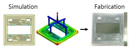
Development of Integrally Molded Bipolar Plates for All-Vanadium Redox Flow Batteries

1
Advanced Institute of Manufacturing with High-tech Innovations and Department of Mechanical Engineering, National Chung Cheng University, No. 168, University Rd., Minhsiung Township, Chiayi 62102, Taiwan
2
Institute of Nuclear Energy Research, Atomic Energy Council, No. 1000 Wenhua Rd., Jiaan Village, Longtan Township, Taoyuan 32546, Taiwan
*
Author to whom correspondence should be addressed.
Energies 2016, 9(5), 350; https://doi.org/10.3390/en9050350
Submission received: 20 February 2016 / Revised: 26 April 2016 / Accepted: 29 April 2016 / Published: 7 May 2016
(This article belongs to the Special Issue Redox Flow Batteries)

Abstract

:
All-vanadium redox flow batteries (VRBs) are potential energy storage systems for renewable power sources because of their flexible design, deep discharge capacity, quick response time, and long cycle life. To minimize the energy loss due to the shunt current, in a traditional design, a flow field is machined on two electrically insulated frames with a graphite plate in between. A traditional bipolar plate (BP) of a VRB consists of many components, and thus, the assembly process is time consuming. In this study, an integrally molded BP is designed and fabricated to minimize the manufacturing cost. First, the effects of the mold design and injection parameters on frame formability were analyzed by simulation. Second, a new graphite plate design for integral molding was proposed, and finally, two integrally molded BPs were fabricated and compared. Results show that gate position significantly affects air traps and the maximum volume shrinkage occurs at the corners of a BP. The volume shrinkage can be reduced using a large graphite plate embedded within the frame.

Graphical Abstract

1. Introduction

Solar and wind energy are not stable power sources because their power generation depends on the weather. To improve their stability and reliability, energy storage systems are needed for saving the excess energy and balancing the energy supply and demand. Among energy storage systems, all-vanadium redox flow batteries (VRBs) have attracted much attention because of their flexible design, quick response time, long cycle life, high energy efficiency, and low maintenance cost [1,2,3,4]. In a VRB system, positive and negative electrolytes are recirculated from a VRB stack to electrolyte storage tanks using pumps; therefore, the energy capacity and power can be separately designed. The energy capacity depends on the amount of electrolytes, whereas the power depends on the size of VRB stacks. The chemical energy of a VRB system is stored in different valence states of vanadium ions (V5+, V4+, V3+ and V2+). Reactions occurring in a VRB are given below. On the positive side:
Energies 09 00350 i001
and on the negative side:
Energies 09 00350 i002
The overall reaction is:
Energies 09 00350 i003
To date, several challenges still hinder commercialization of VRB systems, including their low energy density and the high cost of vanadium species and other key components. A VRB stack generally consists of bipolar plates (BPs), porous electrodes, and an ion-exchange membrane. The major function of BPs in a VRB is to support the stack structure, separate positive and negative electrolytes, and electrically connect electric paths among cells [5].
Many researchers have focused on developing BPs. To reduce the manufacturing cost of traditional graphite plates, carbon–polymer composite materials have been investigated [6]. Because the polymer structure is not electrically conductive, the addition of conductive fillers is critical to achieve the required electrical conductivity. Graphite fiber [7], carbon fiber [8], carbon black [9], and carbon nanotubes [8] have been used as conductive fillers in BPs for fuel-cell applications. Investigations have focused on the dispersion and distribution of fillers, interaction between fillers and polymer matrix, and electrical and mechanical properties of fillers.
BPs for fuel-cell applications cannot be directly used in VRBs owing to the presence of acidic electrolytes in VRBs. Because BPs need to operate in an acidic environment, their chemical stability is critical in the selection of BP materials; however, BPs for VRB applications have not been extensively studied to date. Lee et al. [10,11] developed composite BPs with different polymers and investigated the durability of graphite-coated carbon composite BPs [12]. Caglar et al. [13] used titanate-based coupling agents and carbon nanotubes for bridging graphite particles. Their experimental results showed that the dispersion of fillers improved and the difference between the through- and in-plane electrical conductivities of BPs decreased. Lee et al. [14] developed carbon composite BPs with different carbon black contents via compression molding and showed that such BPs with 15 wt% carbon black exhibited good electrical conductivity and improved electrochemical stability in the working environment of VRBs. Park et al. [15] used aromatic epoxy of diglycidyl ether of bisphenol A as a polymer matrix, diaminodiphenyl sulfone as a curing agent, and graphite flakes and carbon particles as fillers to fabricate BPs and established the optimal composition for stable composite BPs in a VRB stack.
A BP for a VRB consists of two parts: an electrically insulated frame and an electrically conductive graphite plate. Because the electrolytes of a VRB are electrically conductive, shunt current emerges among cells, resulting in performance degradation. The shunt current can be reduced using electrically insulated frames to the periphery of an active area. A common traditional design of a BP is shown in Figure 1a. As shown in the figure, contact faces between graphite and frames require gaskets to avoid electrolyte leakage. Clearly, leakage in a VRB stack needs to be solved.
To the best of our knowledge, the leakage problem of BPs in VRBs has not been extensively studied to date. Some studies focused on improving the bonding between a graphite plate and frame. Soohyun et al. [16] developed a smart cure cycle to reduce the thermal residual stress of a co-cured E-glass/carbon/epoxy composite BP. Using the smart cure cycle, BP deflection decreased by 32%. Sumitomo Electric Industries designed a frame comprising more than 50% vinyl chloride and a composite graphite plate. The frame and graphite plate were bonded to each other with improved adhesives to enhance sealing [17]. They also designed inner and outer seal grooves for gaskets to prevent electrolyte leakage [18]. These studies [16,17,18] focused on preventing leakage between a graphite plate and frame, resulting in increasing manufacturing costs and assembly time. To reduce the number of components, a BP can be fabricated via injection molding. Moreover, the risk of leakage between a graphite plate and frame can be reduced. dos Santos et al. [19] proposed a molded frame with a graphite plate; however, the mold design and injection parameters were not investigated in their report.
In this study, an integrally molded BP is designed and fabricated via injection molding. Figure 1b shows the integrally molded BP. First, the effects of the gate location and injection parameters on frame formability are studied by simulation. The effect of the graphite plate design on formability is also discussed.

2. Mold Design and Analysis

This study aims to develop an integrally molded BP with an active area of 100 cm2. The effects of mold design and injection parameters on BP formability are investigated. A graphite plate with dimensions of 17 cm × 8 cm × 5 cm was machined to 16 cm × 6.5 cm × 1 cm at the centers of both sides of graphite electrodes. Two channels were machined around the active area to prevent electrolyte leakage, as shown in Figure 2a. A flow-field pattern to improve electrolyte distribution, shown in Figure 2b, was designed on an injection-molded frame.

2.1. Governing Equations

The formability of an injected frame depends on the flow behavior of a melted polymer in a mold. During injection molding, the melted polymer is assumed to behave as a generalized Newtonian fluid. A nonisothermal polymer resin in a mold cavity can be described by the following equations:
ρ t + × ρ u = 0
t ( ρ u ) + × ( ρ u u σ ) = ρ g
σ = p I + η ( u + u T )
ρ C p ( T t + u × T ) = ( k T ) + η γ · 2
where u is the velocity vector, T is the temperature, p is the pressure, σ is the total stress tensor, ρ is the fluid density, η is the viscosity, k is the thermal conductivity, Cp is the specific heat, and γ ˙ is the shear rate. In this study, the modified-Cross model with Arrhenius temperature dependence is used to describe the viscosity of melted polymer:
η ( T , γ ˙ ) = η 0 ( T ) 1 + ( η 0 γ ˙ τ * ) 1 n
where:
η 0 ( T ) = B exp ( T b T )
where η0 is the zero shear viscosity, τ* is a parameter to describe the transition region between zero shear rate region and the power law region of the viscosity curve, n is the power law index, B is an exponential-fitted constant, and Tb is a temperature-fitted constant.
Since the behavior of injected material is simulated in Moldex3D, only the completed frame model needs to be constructed, as shown in Figure 3. The frame model was built using SolidWorks and imported to Moldex3D for injection modeling simulation. Before running the simulation, the gate position and operating parameters, such as polymer temperature, molding temperature, injection pressure, maintaining pressure, and ambient temperature, need to be set up in Moldex3D. Polypropylene (PP) was selected as the frame material. The physical properties such as viscosity, specific heat, and specific volume of PP used in the simulation are functions of temperature and were provided by Moldex3D, as shown in Figure 4.

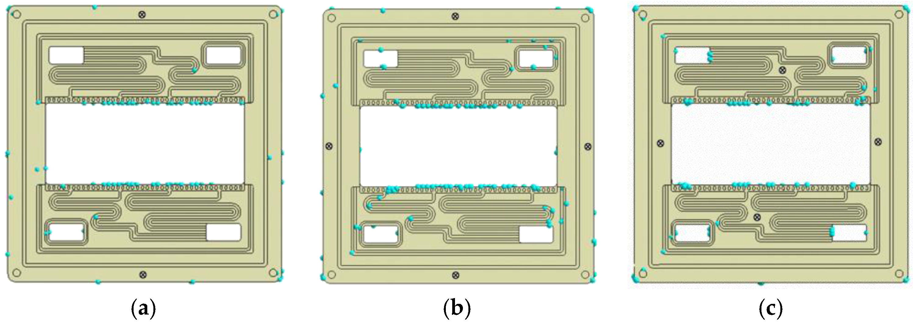
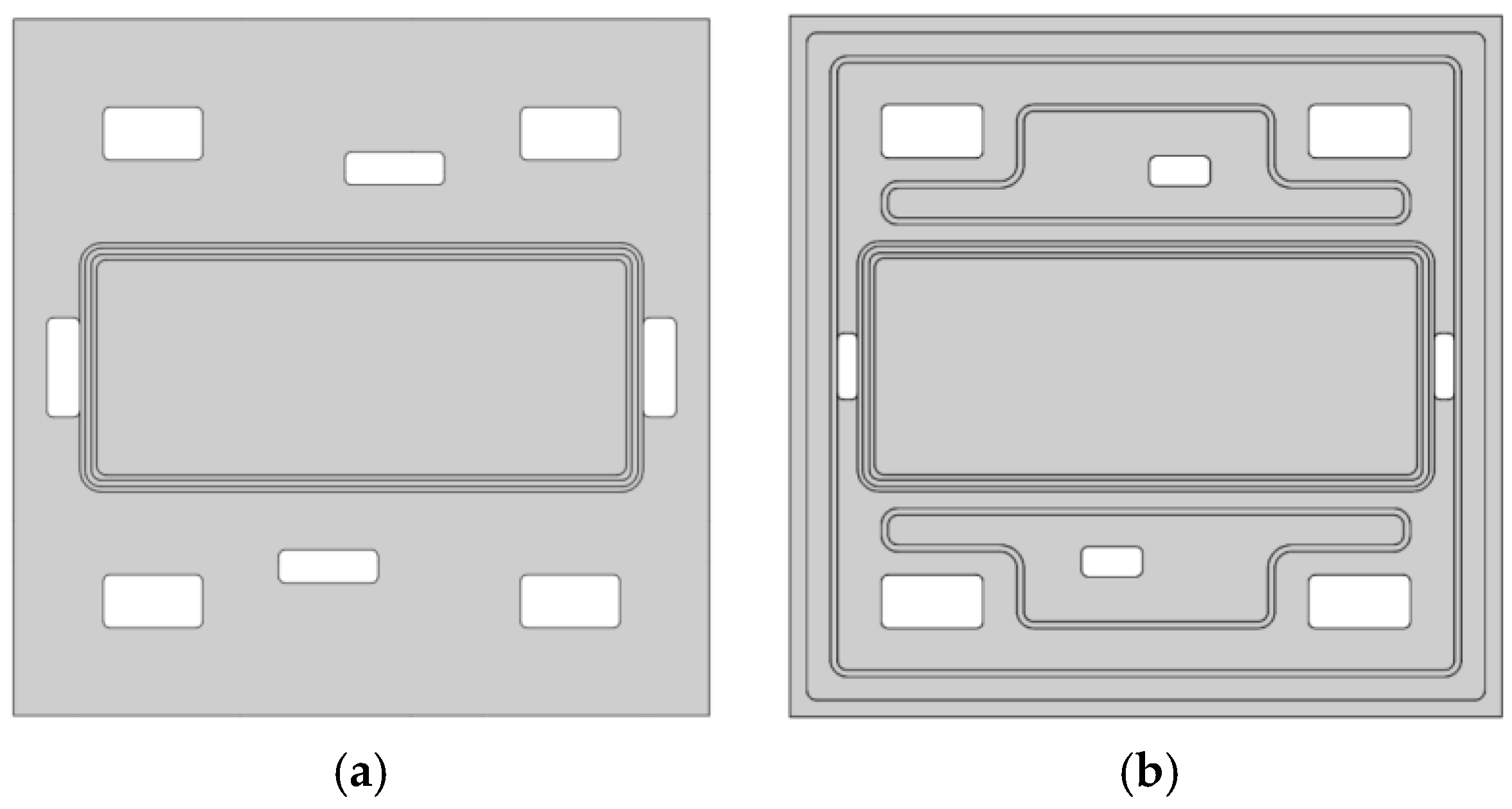
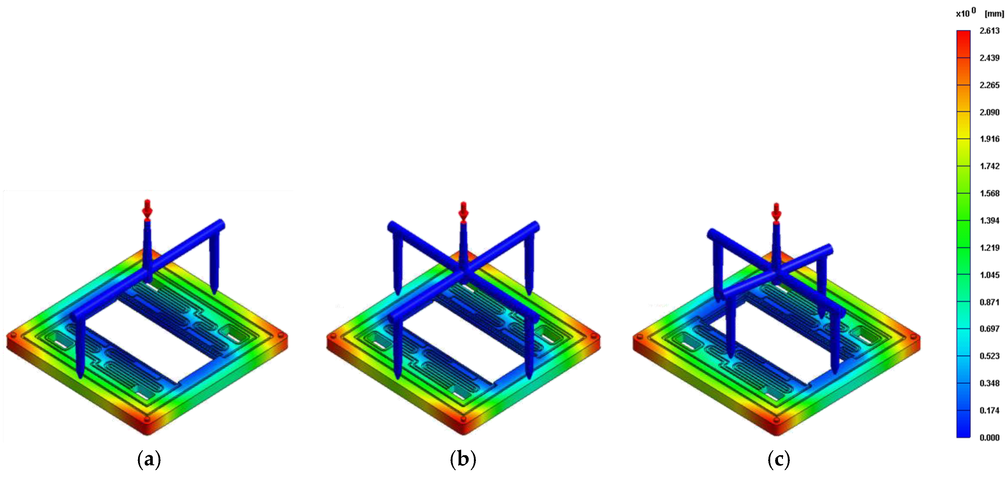
2.2. Position of Injection Gate

Figure 3 shows three gate-position designs. The gate position was on an unremarkable area of the frame; therefore, there were only a few suitable areas on the frame. In G1, two gates were placed at the edge of the frame, as shown in Figure 3a. In G2, four gates were designed at the edge of the frame, as shown in Figure 3b. In G3, two gates were at the edge of the frame and the other two were at the central part of the flow field, as shown in Figure 3c.

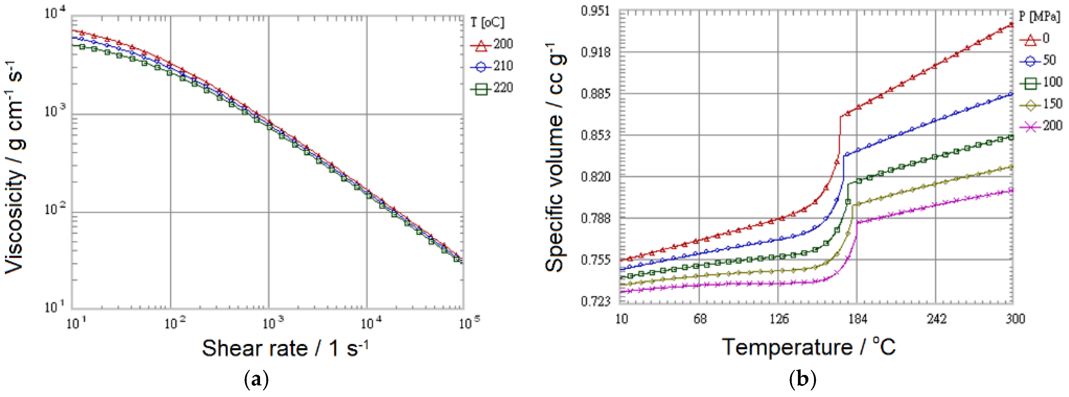
2.3. Injection Parameters

In addition, the software also suggested injection parameters for each commonly used polymer. For example, the suggested parameter values for PP are listed as case P1 in Table 1. In this study, the effects of injection pressure and polymer temperature on BP formability were studied. The injection pressures for P2, P3, and P4 were 100, 180, and 220 MPa, respectively. The melted polymer temperatures for P5 and P6 were 200 °C and 220 °C, respectively. In all simulation cases, the molding temperature was 60 °C and the ambient temperature was 25 °C.

3. Results and Discussion

The effects of the position of the injection gate and injection parameters on formability are discussed in the following sections.

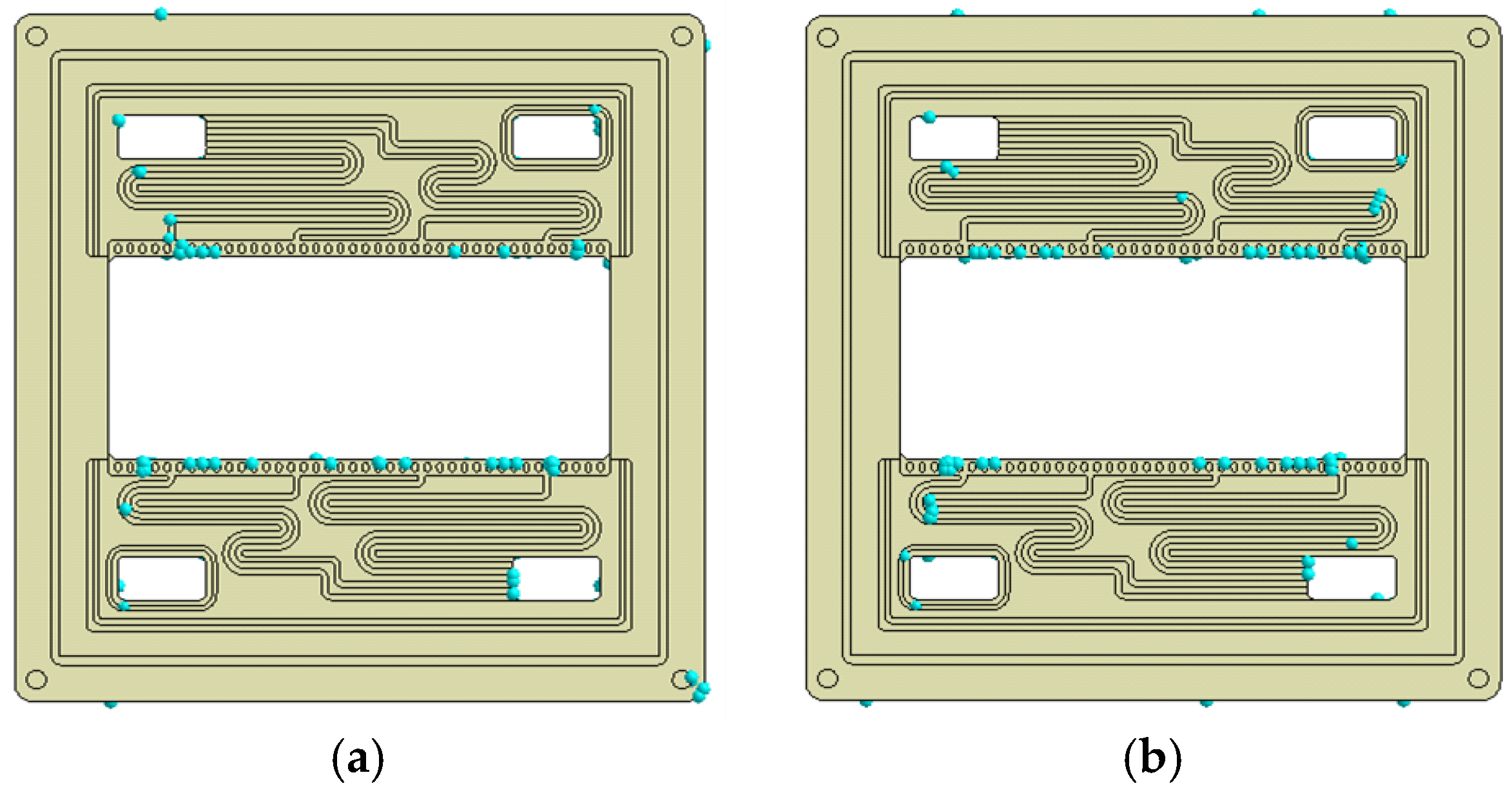
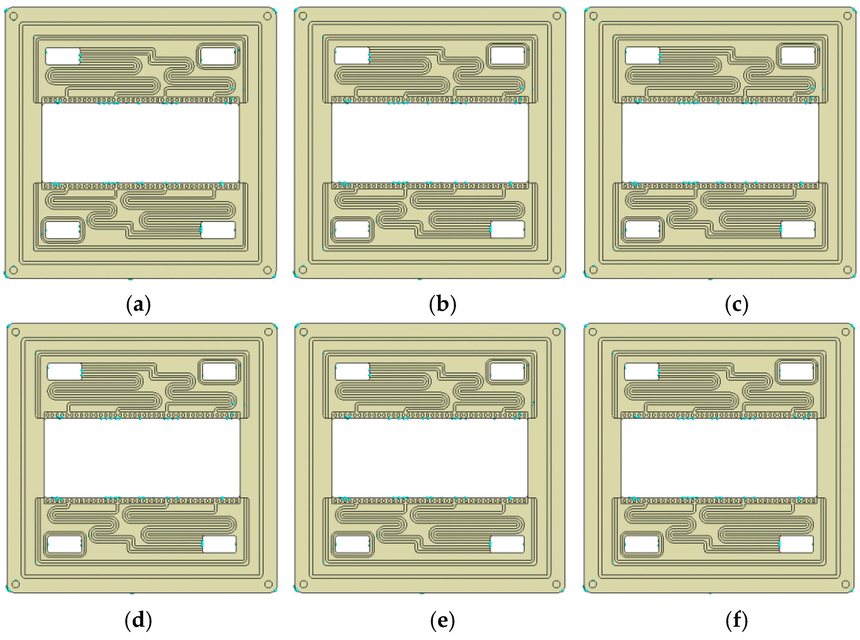
3.1. Effect of Gate Position on Formability

The formability of molded products can be evaluated by a number of air traps and volume shrinkage. Air traps are usually located in areas where melted polymer fills last. Trapped air will result in bubbles or voids within the molded part, or surface defects. Volume shrinkage may cause dimensional errors, resulting in electrolyte leakage. It is desired to minimize the number of air traps and volume shrinkage when considering gate positions. For the BP of a VRB, there are only a few positions suitable for placing gates. Before the filling stops, injected materials are expected to completely fill all spaces in a simultaneous manner while maintaining uniform pressure distribution. The effect of the gate position on air traps is shown in Figure 5. The number of air trap can be quantified by Moldex3D. It can be seen that the number of air traps in G3 is 112, which is fewer than 178 in G1 and 175 in G2, because gates at the center of the flow field help to distribute injected materials from the central area.
Figure 6 shows the volume shrinkage of the integrally molded BPs for G1, G2, and G3. Although gate position influences the number of air trap, it shows little effect on the volume shrinkage. In all three cases, the maximum shrinkage is approximately 2.61 mm at the four corners.

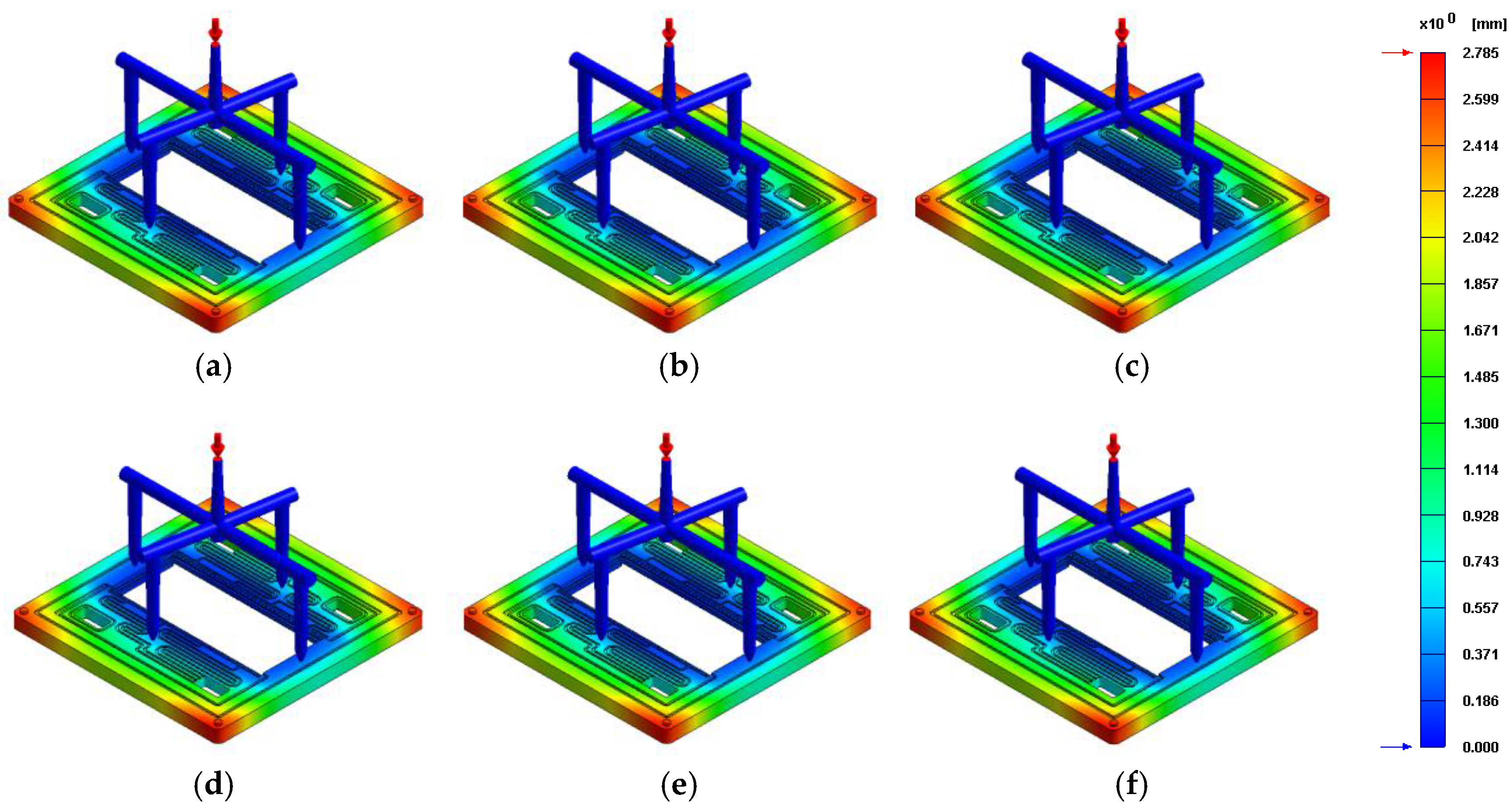
3.2. Effect of Injection Parameters on Formability

Figure 7 shows air traps in the simulation results for P1, P2, P3, P4, P5, and P6. The effect of injection pressure on formability can be investigated by comparing Figure 7a–d. It can be seen that when the injection pressure varies from 100 MPa to 220 MPa, the locations of air traps are almost the same as those in P1 and the numbers of air traps for the two cases are 112.
By comparing Figure 7a,e and f, it is observed that when the polymer temperature is increased from 200 °C to 220 °C, the number and location of air traps show some minor variation, but no obvious trend observed, 109 for P5 and 103 for P6. Furthermore, volume shrinkages in all cases (P1 to P6) are between 2.6 and 2.8 mm, as shown in Figure 8. Maximum shrinkage occurs at the four corners of the molded frame. According to Figure 7 and Figure 8, selecting different injection parameter values than the suggested ones does not significantly reduce volume shrinkage.
On the basis of the discussions in the previous sections, air traps can be reduced by selecting an appropriate gate position; however, volume shrinkage cannot be significantly reduced by varying the gate positions or injection parameters. Because there is no graphite plate within the corner area of the frame to support polymer materials, maximum shrinkage occurs at the four corners.

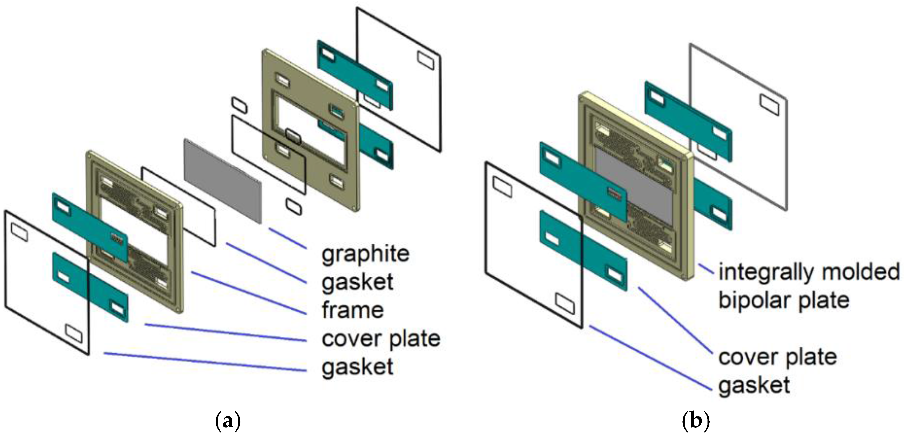
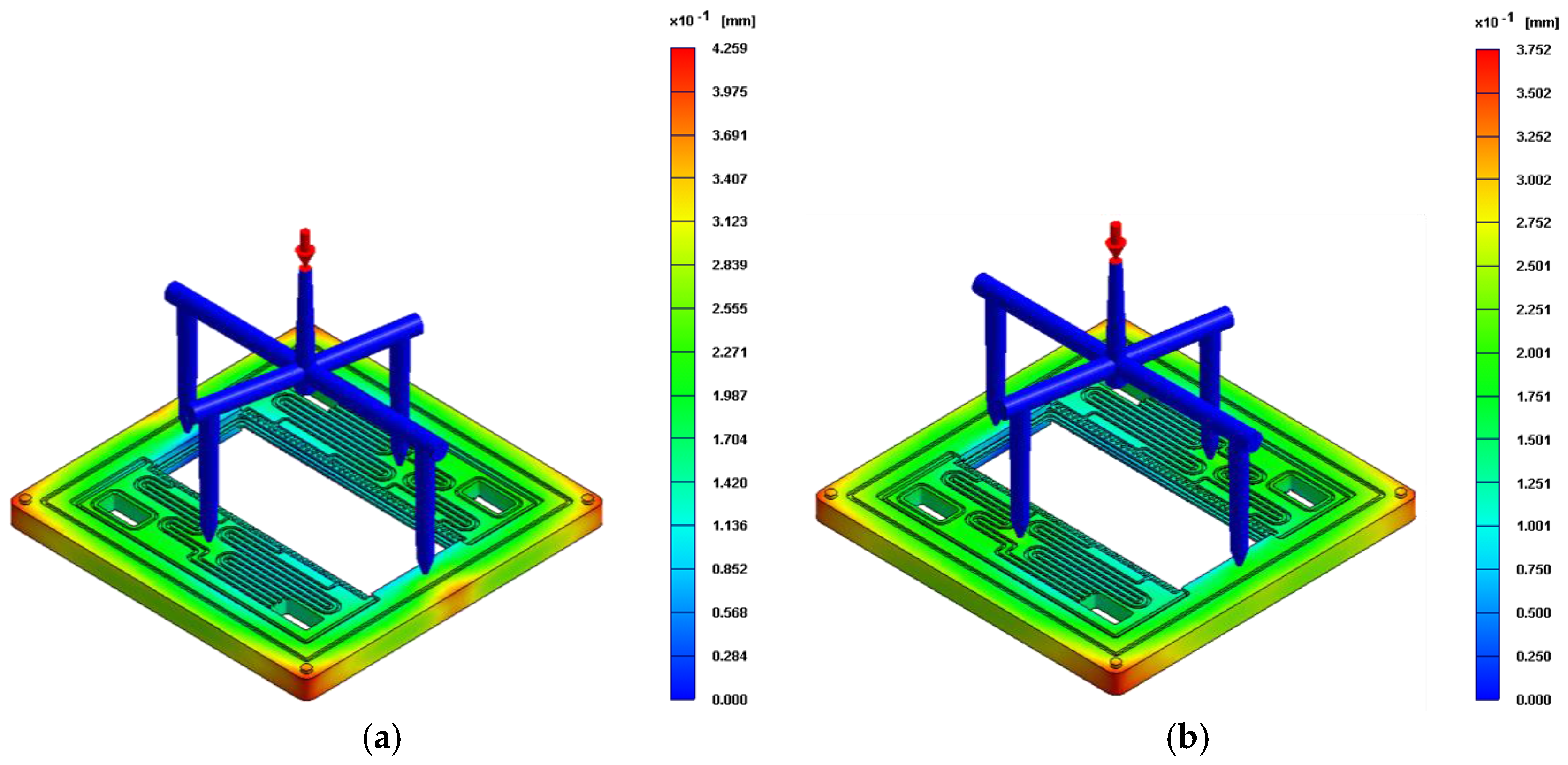
3.3. Improved Design of Bipolar Plates

Volume shrinkage occurs at a relatively thicker injected material outside the graphite plate area. Thus, to minimize shrinkage around the corners, the graphite plate is redesigned to have a larger area so that the thickness of the injected material covering the graphite plate can be reduced. Figure 9 shows two new graphite plate designs: one without ribs around the periphery, as shown in Figure 9a, and the other with ribs to enhance the bending strength, as shown in Figure 9b.
The simulated air traps in injected BPs for D2 and D3 are shown in Figure 10. The numbers of air traps for D2 and D3 are 134 and 158, respectively, which are more than that of the original design (G3). Because the gate position is the same in all three designs, it is expected that a secondary flow field is the last area wherein the injected material is filled. As a result, the graphite design does not affect air traps; it is the gate location that affects the traps.
The simulated volume shrinkages of D2 and D3 are shown in Figure 11. Maximum shrinkages are approximately 0.43 and 0.38 mm for D2 and D3, respectively. Compared with the original design (G3), a relatively larger graphite plate significantly reduces the shrinkage of injected materials. The simulation results of D3 show less volume shrinkage than those of D2. Because of the rib around the periphery of the graphite plate in D3, both the thickness of the injected polymer material at the corners and volume shrinkage are reduced.
Figure 12 shows the integrally molded BPs with different embedded graphite plates. In Figure 12a a BP with a relatively smaller graphite plate exhibits notable volume shrinkage at the four corners. When the graphite plate is replaced by a relatively larger one, volume shrinkage at the corners is significantly reduced, as shown in Figure 12b. Although volume shrinkage can be minimized by appropriately designing an embedded graphite plate, the flatness of the molded BPs is also critical to the stack assembly. Thus, in the future, the flatness of the molded BPs will be investigated.

4. Conclusions

BPs are key components of VRBs. To reduce the number of components and simplify the assembling process, integrally molded BPs are designed and fabricated. The effects of the gate position and injection parameters on BP formability were investigated by simulation using commercial software Modex3D. The conclusions derived are as follows:
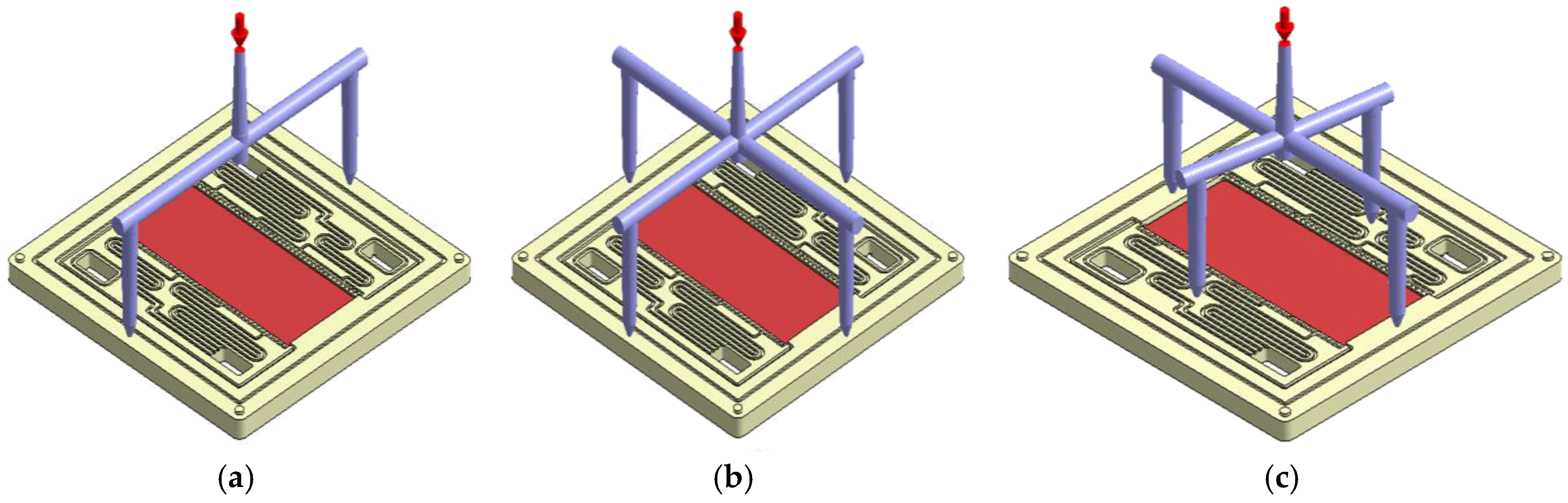
  • Gate position significantly affects air traps. Gates located at the central part of a flow field reduce the number of air traps.
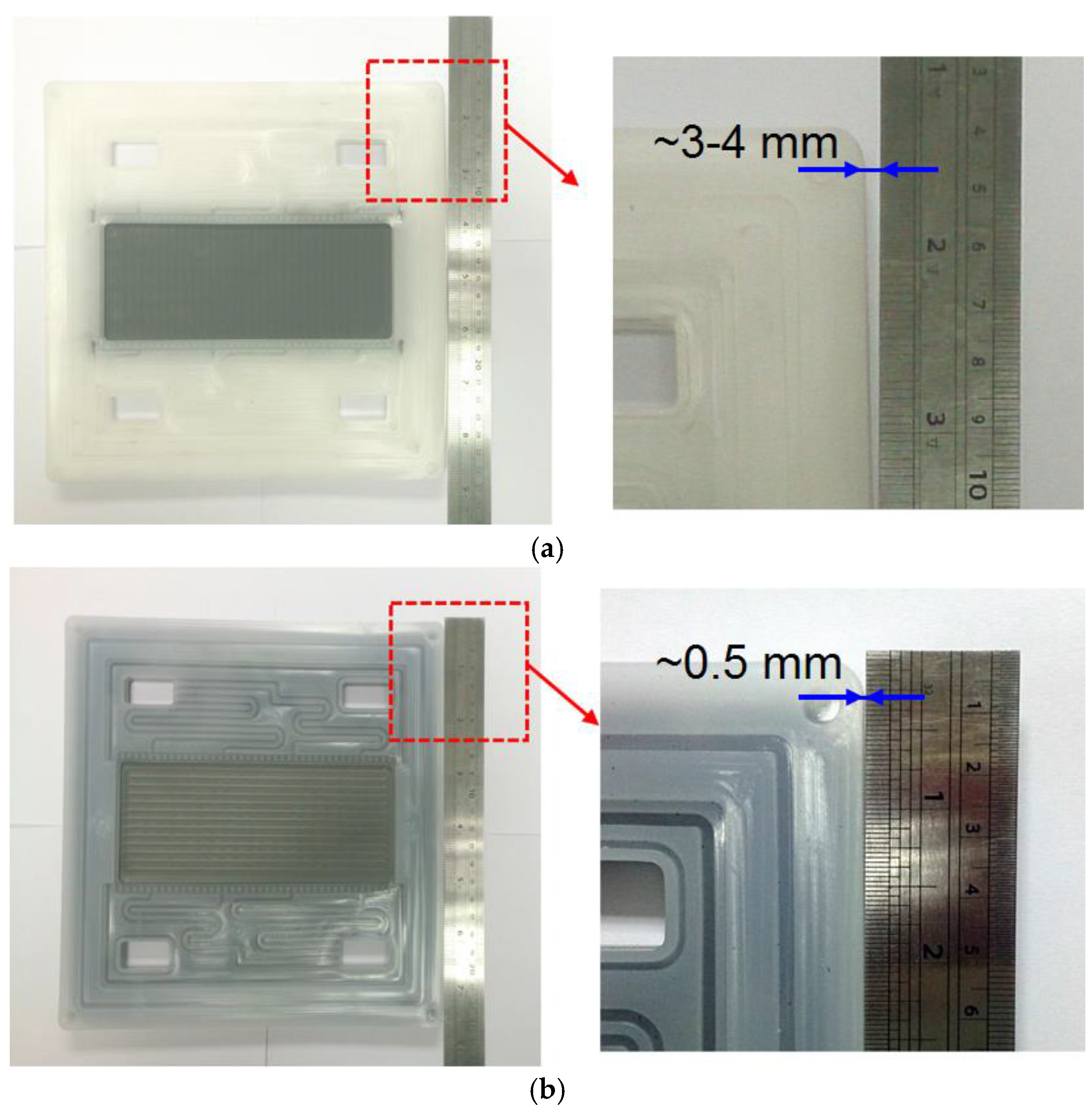
  • Maximum volume shrinkage occurs at the corners of a BP owing to the relatively thicker injected material.
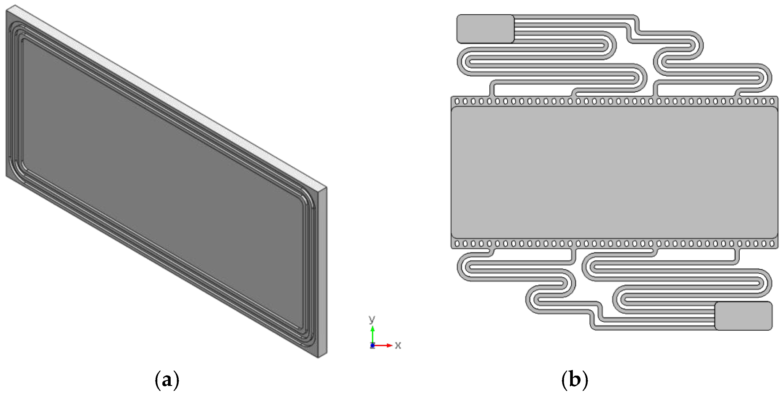
  • Volume shrinkage can be reduced using a large graphite plate with the maximum shrinkage of approximately 0.4 mm at the corners.

Acknowledgments

The authors gratefully thank the Bureau of Energy, Ministry of Economic Affairs, Taiwan, and the Institute of Nuclear Energy Research of Taiwan for the financial support for this study under Project No. 104-D0115.

Author Contributions

All authors read and approved the manuscript. Chih-Hsun Chang performed the simulation. Han-Wen Chou performed experiments and checked simulation results. Ning-Yih Hsu thoroughly reviewed literature and provided precious advice on the structure of this article. Yong-Song Chen provided the main idea of this work and prepared the manuscript.

Conflicts of Interest

The authors declare no conflict of interest.

References

  1. Rychcik, M.; Skyllas-Kazacos, M. Characteristics of a new all-vanadium redox flow battery. J. Power Sources 1988, 22, 59–67. [Google Scholar] [CrossRef]
  2. Skyllas-Kazacos, M.; Kazacos, G.; Poon, G.; Verseema, H. Recent advances with UNSW vanadium-based redox flow batteries. Int. J. Energy Res. 2010, 34, 182–189. [Google Scholar] [CrossRef]
  3. Sun, B.; Skyllas-Kazacos, M. Modification of graphite electrode materials for vanadium redox flow battery application—I. Thermal treatment. Electrochim. Acta 1992, 37, 1253–1260. [Google Scholar] [CrossRef]
  4. Sun, B.; Skyllas-Kazacos, M. Chemical modification of graphite electrode materials for vanadium redox flow battery application—Part II. Acid treatments. Electrochim. Acta 1992, 37, 2459–2465. [Google Scholar] [CrossRef]
  5. Haddadi-Asl, V.; Kazacos, M.; Skyllas-Kazacos, M. Carbon–polymer composite electrodes for redox cells. J. Appl. Polym. Sci. 1995, 57, 1455–1463. [Google Scholar] [CrossRef]
  6. Hagg, C.M.; Skyllas-Kazacos, M. Novel bipolar electrodes for battery applications. J. Appl. Electrochem. 2002, 32, 1063–1069. [Google Scholar] [CrossRef]
  7. Kuan, H.-C.; Ma, C.-C.M.; Chen, K.H.; Chen, S.-M. Preparation, electrical, mechanical and thermal properties of composite bipolar plate for a fuel cell. J. Power Sources 2004, 134, 7–17. [Google Scholar] [CrossRef]
  8. Antunes, R.A.; de Oliveira, M.C.L.; Ett, G.; Ett, V. Carbon materials in composite bipolar plates for polymer electrolyte membrane fuel cells: A review of the main challenges to improve electrical performance. J. Power Sources 2011, 196, 2945–2961. [Google Scholar] [CrossRef]
  9. Dweiri, R.; Sahari, J. Electrical properties of carbon-based polypropylene composites for bipolar plates in polymer electrolyte membrane fuel cell (PEMFC). J. Power Sources 2007, 171, 424–432. [Google Scholar] [CrossRef]
  10. Kim, K.H.; Kim, B.G.; Lee, D.G. Development of carbon composite bipolar plate (BP) for vanadium redox flow battery ( VRFB ). Compos. Struct. 2014, 109, 253–259. [Google Scholar] [CrossRef]
  11. Lim, J.W.; Lee, D.G. Carbon fiber / polyethylene bipolar plate-carbon felt electrode assembly for vanadium redox flow batteries ( VRFB ). Compos. Struct. 2015, 134, 483–492. [Google Scholar] [CrossRef]
  12. Choe, J.H.; Lim, J.W.; Kim, M.K.; Kim, J.H.; Lee, D.G. Durability of graphite coated carbon composite bipolar plates for vanadium redox flow batteries. Compos. Struct. 2015, 134, 106–113. [Google Scholar] [CrossRef]
  13. Caglar, B.; Fischer, P.; Kauranen, P.; Karttunen, M.; Elsner, P. Development of carbon nanotube and graphite filled polyphenylene sulfide based bipolar plates for all-vanadium redox flow batteries. J. Power Sources 2014, 256, 88–95. [Google Scholar] [CrossRef]
  14. Lee, N.J.; Lee, S.W.; Kim, K.J.; Kim, J.H.; Park, M.S.; Jeong, G.; Kim, Y.J.; Byun, D. Development of carbon composite bipolar plates for vanadium redox flow batteries. Bull. Korean Chem. Soc. 2012, 33, 3589–3592. [Google Scholar] [CrossRef]
  15. Park, M.; Jung, Y.-J.; Ryu, J.; Cho, J. Material selection and optimization for highly stable composite bipolar plates in vanadium redox flow batteries. J. Mater. Chem. A 2014, 2, 15808–15815. [Google Scholar] [CrossRef]
  16. Soohyun, N.; Dongyoung, L.; Ilbeom, C.; Dai Gil, L. Smart cure cycle for reducing the thermal residual stress of a co-cured E-glass/carbon/epoxy composite structure for a vanadium redox flow battery. Compos. Struct. 2015, 120, 107–116. [Google Scholar] [CrossRef]
  17. Nakaishi, H.; Kanno, T.; Ogino, S.; Ito, T.; Shigematsu, T.; Tokuda, N. Cell Frame for Redox-Flow Cell and redox-Flow Cell. U.S. Patent 20040202915, 14 October 2004. [Google Scholar]
  18. Nakaishi, H.; Kanno, T.; Ogino, S.; Ito, T.; Shigematsu, T.; Tokuda, N. Cell Frame for Redox-Flow Battery and Redox-Flow Battery. U.S. Patent 20080081247, 3 April 2008. [Google Scholar]
  19. Dos Santos, A.R.; Chromik, A.; Kerres, J.; Düerkop, D.; Widdecke, H.; Hickmann, T.; Turek, T.; Kunz, U. Development of improved bipolar plates for vanadium redox-flow batteries with functionality integration. In Proceedings of the 2014 International Flow Battery Forum, Hamberg, Germany, 1–2 July 2014.
Figure 1. Comparison between: (a) a traditional bipolar plate (BP); and (b) an integrally molded BP.
Energies 09 00350 g001
Figure 2. (a) Design of the graphite plate; and (b) flow-field pattern for electrolyte distribution.
Energies 09 00350 g002
Figure 3. Gate positions: (a) G1, two gates at the edge of the frame; (b) G2, four gates at the edge of the frame; and (c) G3, two gates at the edge of the frame and the other two at the central part of flow field.
Energies 09 00350 g003
Figure 4. Properties provided by Moldex3D: (a) relationship between viscosity and shear rate; and (b) relationship between specific volume and temperature.
Energies 09 00350 g004
Figure 5. Location of air traps in three gate positions: (a) G1 (178), (b) G2 (175), and (c) G3 (112). (The value in parentheses indicates the number of air traps.)
Energies 09 00350 g005
Figure 6. Effect of gate position on volume shrinkage: (a) G1; (b) G2; and (c) G3.
Energies 09 00350 g006
Figure 7. Effects of injection parameters on air traps: (a) P1 (112), (b) P2 (112), and (c) P3 (112), (d) P4 (112), (e) P5 (109), and (f) P6 (103). (The value in parentheses indicates the number of air traps.)
Energies 09 00350 g007
Figure 8. Effects of injection parameters on volume shrinkage: (a) P1; (b) P2; (c) P3; (d) P4; (e) P5; and (f) P6.
Energies 09 00350 g008
Figure 9. Improved designs of the graphite plate: (a) D2, without ribs; and (b) D3, with ribs.
Energies 09 00350 g009
Figure 10. Location of air traps for improved designs of graphite plates: (a) D2 (134) and (b) D3 (158). (The value in parentheses indicates the number of air traps.)
Energies 09 00350 g010
Figure 11. Volume shrinkage of injected materials for: (a) D2; and (b) D3.
Energies 09 00350 g011
Figure 12. Pictures of integrally molded BPs for: (a) G3; and (b) D3.
Energies 09 00350 g012
Table 1. Injection parameters used in the simulation.
Injection ParametersP1P2P3P4P5P6
Polymer temperature (°C)210210210210200220
Molding temperature (°C)606060606060
Injection pressure (MPa)140100180220140140
Maintaining pressure (MPa)140100180220140140
Ambient temperature (°C)252525252525

