Article

Aerodynamic Analysis and Three-Dimensional Redesign of a Multi-Stage Axial Flow Compressor

1
Key Laboratory for Thermal Science and Power Engineering of Ministry of Education, Department of Thermal Engineering, Tsinghua University, Beijing 100084, China
2
Collaborative Innovation Center of Advanced Aero-Engine, Beijing 100191, China
3
Shenyang Engine Design and Research Institute (SEDRI), Shenyang 110000, China
*
Author to whom correspondence should be addressed.
Energies 2016, 9(4), 296; https://doi.org/10.3390/en9040296
Submission received: 14 September 2015 / Revised: 29 March 2016 / Accepted: 11 April 2016 / Published: 16 April 2016

Abstract

:
This paper describes the introduction of three-dimension (3-D) blade designs into a 5-stage axial compressor with multi-stage computational fluid dynamic (CFD) methods. Prior to a redesign, a validation study is conducted for the overall performance and flow details based on full-scale test data, proving that the multi-stage CFD applied is a relatively reliable tool for the analysis of the follow-up redesign. Furthermore, at the near stall point, the aerodynamic analysis demonstrates that significant separation exists in the last stator, leading to the aerodynamic redesign, which is the focus of the last stator. Multi-stage CFD methods are applied throughout the three-dimensional redesign process for the last stator to explore their aerodynamic improvement potential. An unconventional asymmetric bow configuration incorporated with leading edge re-camber and re-solidity is employed to reduce the high loss region dominated by the mainstream. The final redesigned version produces a 13% increase in the stall margin while maintaining the efficiency at the design point.

1. Introduction

High performance requirements and cost reduction were proposed for the development of modern aero engines and heavy-duty gas turbines, which improve the compressor design with higher loading, fewer stage counts and a shorter axial distance. Consequently, modern compressors have challenging aerodynamic designs because the larger adverse pressure gradient and stronger blade row interaction lead to internal turbulent flow with high three-dimensionality and nonlinearity. The highly three-dimensional flow in modern compressors also makes it difficult to evaluate the aerodynamic performance, resulting in the high cost and risk of compressor development.
Two main approaches are employed in the aerodynamic analysis and design of compressors. The first is the through-flow code, which is a traditional quasi-three-dimension (quasi-3D) method based on streamline curvature equations. The through-flow code was the main tool for compressor performance predictions two decades ago, with the advantage of quickly and effectively predicting performance [1,2,3]. However, the through-flow code typically requires the input of many empirical parameters, such as blockage, loss and deviation, which are dependent on the design history. The larger number of inputs limits the application of the code in compressor design beyond the state of the art and suppresses the improvement potential of modern design performance because proper correlation models and empirical data are unavailable. However, through-flow is very important for determining the general compressor design and assembly, especially for one-dimension (1-D) and two-dimension (2-D) designs.
With the recent rapid development of computer science and computational fluid dynamic (CFD) technology, a fully viscous, 3-D CFD method has played a key role in the development of modern compressors, especially for the advanced 3-D design, by providing detailed flow fields without an empirical parameter input. In particular, after the introduction of steady multi-stage CFD approaches in the early 1990s, a breakthrough was achieved for the aerodynamic analysis and design philosophy of turbomachinery. Two main blade row-coupling models exist for modeling and simulating turbomachinery in a multi-stage environment: the average-passage approach and the mixing plane approach. The average-passage approach was developed by Adamczyk [4,5] and accounts for the unsteady deterministic flow and blade-row interaction as the body force and source terms of the passage-averaged equations. The CFD code APNASA by National Aeronautics and Space Administration (NASA) is a typical representation of the average-passage approach, which was used in enormous multi-stage compressor analysis and design [6,7,8,9,10,11]. In the mixing plane approach, the flow variables of the interface planes between the stationary and rotating blade rows are averaged circumferentially and exchanged as the boundary between neighboring blade rows. This approach is used in the commercial CFD codes NUMECA-Fine/Turbo and ANSYS-CFX and has been widely employed in multi-stage compressor analyses in recent years [11,12,13,14,15].
Many researchers, including Adamczyk [7], Wellborn [10], Brilliant [16], Mansour [11], and Ikeguchi [15], successfully developed multi-stage CFD methods to reduce development costs and gain performance improvement. In the last two decades, with the extensive application of multi-stage CFD methods and the development of advanced high-fidelity CFD methods [17,18,19], CFD technologies have improved compressor aerodynamics and revolutionized the philosophy of compressor design. Indeed, the development of large novel 3-D blading design concepts, including bow [20,21], sweep [22,23], re-camber [23], and blended blade and endwall (BBEW) [24], can be mainly attributed to the application of CFD technology, which leads to improved and more highly three-dimensional design philosophies for compressor aerodynamics. In turn, this revolution produces many benefits for increasing the machine’s loading capacity beyond the current state-of-the-art technology.
Nevertheless, most of the 3-D blading techniques researched by CFD methods mainly only concentrated on the isolated or part-stage blade row environments and were relatively limited in the entire multi-stage environment. The effects of 3-D blading are significantly determined by 3-D internal flow structures on modern compressors with high three dimensionality and strong blade row interactions, which may be rather different between the isolated and multi-stage environment. Therefore, it is worth applying multi-stage CFD methods to capture the realistic physics and understand the mechanism of 3-D blading in the multi-stage environment. However, multi-stage CFD methods are not without limits. As noted by Denton [25], the main issues facing CFD users include uncertainties of the reliability of CFD due to the numerical errors, modeling errors, steady flow assumption, and so on. Therefore, it is essential to conduct validation research on multi-stage CFD methods based on test data to guarantee the validity and reliability of CFD methods applied in the design process.
Currently, CFD is frequently integrated into a state-of-the-art blade design system coupled with automatic multi-objective optimization. The optimization system typically includes geometry generation tools, optimization algorithms, CFD and finite element method (FEM) solvers, as well as artificial neural networks (ANNs) to speed up the optimization process, which involves mechanical, thermal, and aerodynamic analyses [26,27,28]. This paper focuses on the 3-D aerodynamic redesign of a 5-stage compressor with multi-stage CFD methods, with the purpose of developing the next upgrade version of this type of compressor.

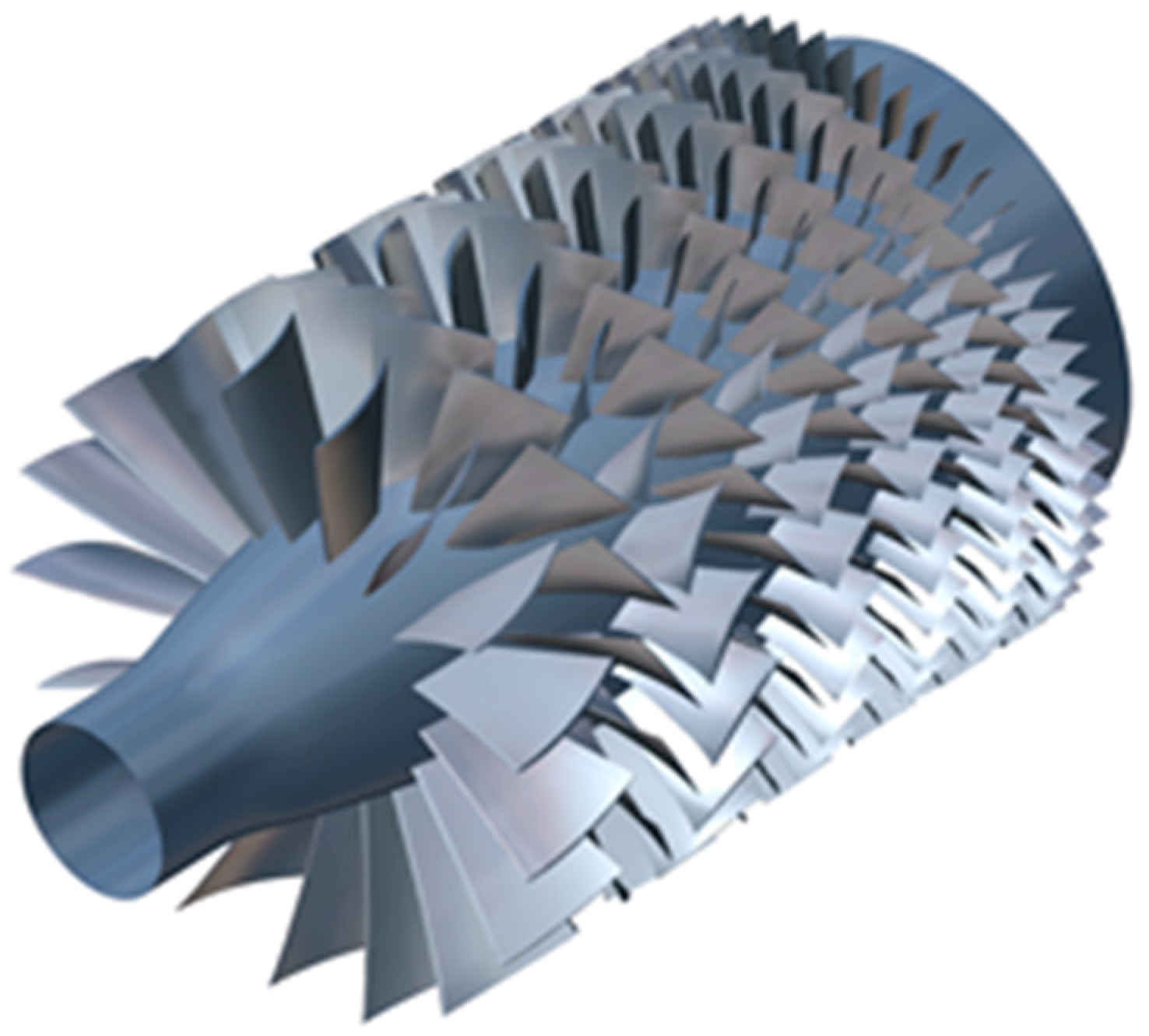
2. Compressor Overview

The highly loaded 5-stage compressor is designed for developing a modern industrial gas turbine; the overall compressor configuration is illustrated in Figure 1. A high loading design strategy is applied in the design process. MCA airfoils are used for the transonic rotor of the first stage, whereas CDA profiles are employed in the design of the remainder of the subsonic blades. The inlet guided vane (IGV) and first two stators are variable for surge control at partial speed. However, other detailed compressor design specifications cannot be provided in this work because of the proprietary nature of the information. A full-scale rig test was conducted at the Shenyang Engine Design and Research Institute (SEDRI). The overall performance data, the measured casing static pressure and the flow profiles at the leading edge of the stators were obtained for both design and off-design conditions.

3. CFD Computational Method

3.1. Numerical Scheme

Multistage CFD methods are applied in the aerodynamic analysis and redesign process with the commercial CFD software “Fine/Turbo” [29], where the 3D Reynolds-Averaged Navier-Stokes (RANS) equations are solved using a cell-centered finite volume approach. After calibration of several turbulence models, single passage steady simulations are conducted using the Spalart-Allmaras turbulence model [30]. The second-order upwind scheme for spatial discretization and the four-stage Runge-Kutta scheme for time discretization are employed for the solver. Moreover, a multigrid approach is applied to accelerate the convergence. In particular, the mixing plane approach is used as the rotor-stator interface strategy. Air (perfect gas) is applied as the simulation fluid.

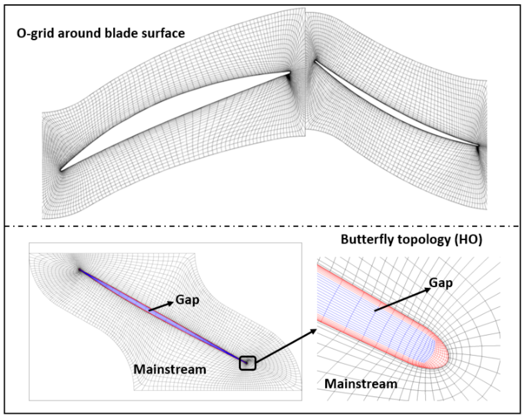
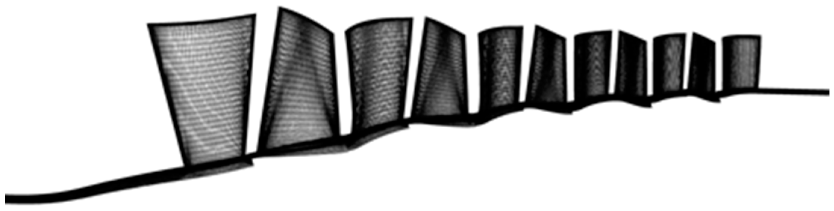
3.2. Computational Mesh

The rotor tip clearances and variable stator clearances are considered to be simple constant span gaps. The mesh is generated using structured hex elements, employing a HOH (inlet, O, and outlet blocks) mesh topology, with an O-grid covering the blade surface. The rotor tips and variable stator clearances are filled with butterfly mesh blocks (HO mesh topology) using a non-matching mesh interface with a mainstream domain, as demonstrated in Figure 2.
A mesh-dependence test is carried on three mesh sizes of four million, six million and eight million. A total mesh size of six million for the 11 blade passage, including IGV and five stages (rotor and stator), is adopted. To guarantee the mesh quality, the minimum grid skewness is approximately 18 degrees. The distance between the first grid line and the solid wall is set to y+ < 10. An overview of the mesh for the 5-stage compressor is presented in Figure 3.

3.3. Boundary Conditions

A total pressure profile and inlet flow angle profile are specified at the inlet based on the test data, while a radial pressure gradient to match the radial equilibrium condition is specified at the outlet. Moreover, one-blade passage flows are simulated with the periodic conditions applied on the pitchwise boundaries of the flow domain. Nonslip and adiabatic conditions are adopted for all of the solid walls. In particular, rotors are calculated in the rotating frame of reference, while the hub surface is defined as a stationary wall; the casing surface is defined as a counter-rotating wall in the rotating frame of reference.

4. Aerodynamic Analysis

Multi-stage CFD methods are used for the detailed aerodynamic analysis of the baseline compressor to put forward recommendations for redesign efforts. The entire redesign process is conducted in the multi-stage environment, even for a single blade. Therefore, it is essential to carefully conduct validation research on the multi-stage CFD methods applied in this paper prior to aerodynamic redesign.
Test data from the full-scale rig are used for validation. The overall performance is compared with the experimental data, and details of the flow fields, such as the casing static pressure and total pressure profiles at the leading edge of stator 4 and stator 5, are presented for validation at the design and off-design operating points (near the stall). The experimental and computational performance data presented below are normalized using the same normalization factors taken from the rig conditions at the design point. The measured and predicted overall performances of the 5-stage compressor at design speed are presented in Figure 4. Compared with the test data, it is clear that the shape of the speed line predicted by the multi-stage CFD is similar to the experimental line, where the error bars were derived based on one standard deviation. The deviation of the peak adiabatic efficiency (total to total) between the CFD calculation and experiment is within 0.5%. The CFD slightly over-predicts the mass flow rate by approximately 0.4%. Above all, the overall performance of this 5-stage compressor is well predicted.
The predicted static pressure on the casing is compared with test data at the design and near stall points as shown in Figure 5. The relative axial distance position 0 corresponds to the IGV inlet, while position 1 represents the position of the stator 5 outlet. The casing static pressure of the CFD model and experiment is non-dimensionalized by the outlet casing static pressure of the CFD model at the design point. The maximum difference between the predicted casing static pressure and the test data is approximately 5%.
Figure 6 shows the measured and predicted total pressure profiles at the leading edges of stator 4 and stator 5, where the total pressure is non-dimensionalized by the averaged outlet total pressure of the test rig at the design point. The agreement between the experimental and CFD results is satisfactory, except for a deviation at the tip region.
To summarize, the multistage CFD methods applied in the present research can predict the overall compressor performance well. Furthermore, the prediction of the casing static pressure and spanwise total pressure profiles is good. CFD methods are applied for further aerodynamic analysis and aerodynamic redesign below.
The calculation results are analyzed to further examine the flow fields of the baseline compressor to propose the aerodynamic redesign strategies in the next section. In Figure 7, the limiting streamlines on the suction side of the compressor near the stall point indicate that no remarkable flow separation occurs, except in stator 5. It is obvious that stator 5 suffers separations on the suction side across the span, which causes the machine to stall. Figure 8 shows the streamwise distributions of the diffusion factor at the 20%, 50% and 80% spans for the design and near stall points. It is clear that the diffusion factors of the last two stages are much higher than in the other stages, especially for the stators. Additionally, the operating condition of the last stator is the most serious, especially for the hub and middle span regions, where the diffusion factors exceed 0.6. Furthermore, Figure 9 shows the surface static pressure rise coefficient distribution at the 20%, 50% and 80% spans of stator 5 for the design point and near the stall point. These results indicate that stator 5 operates in a high positive incidence even at the design point, which is obviously not a satisfied operating condition. At the near stall point, the incidence of the middle span is larger than that of the hub and tip, which is in agreement with Figure 8. According to the above analysis, the aerodynamic redesign of a baseline compressor should be the focus of the last stator to improve the performance and operating stability of the compressor.

5. Three-Dimensional Redesign
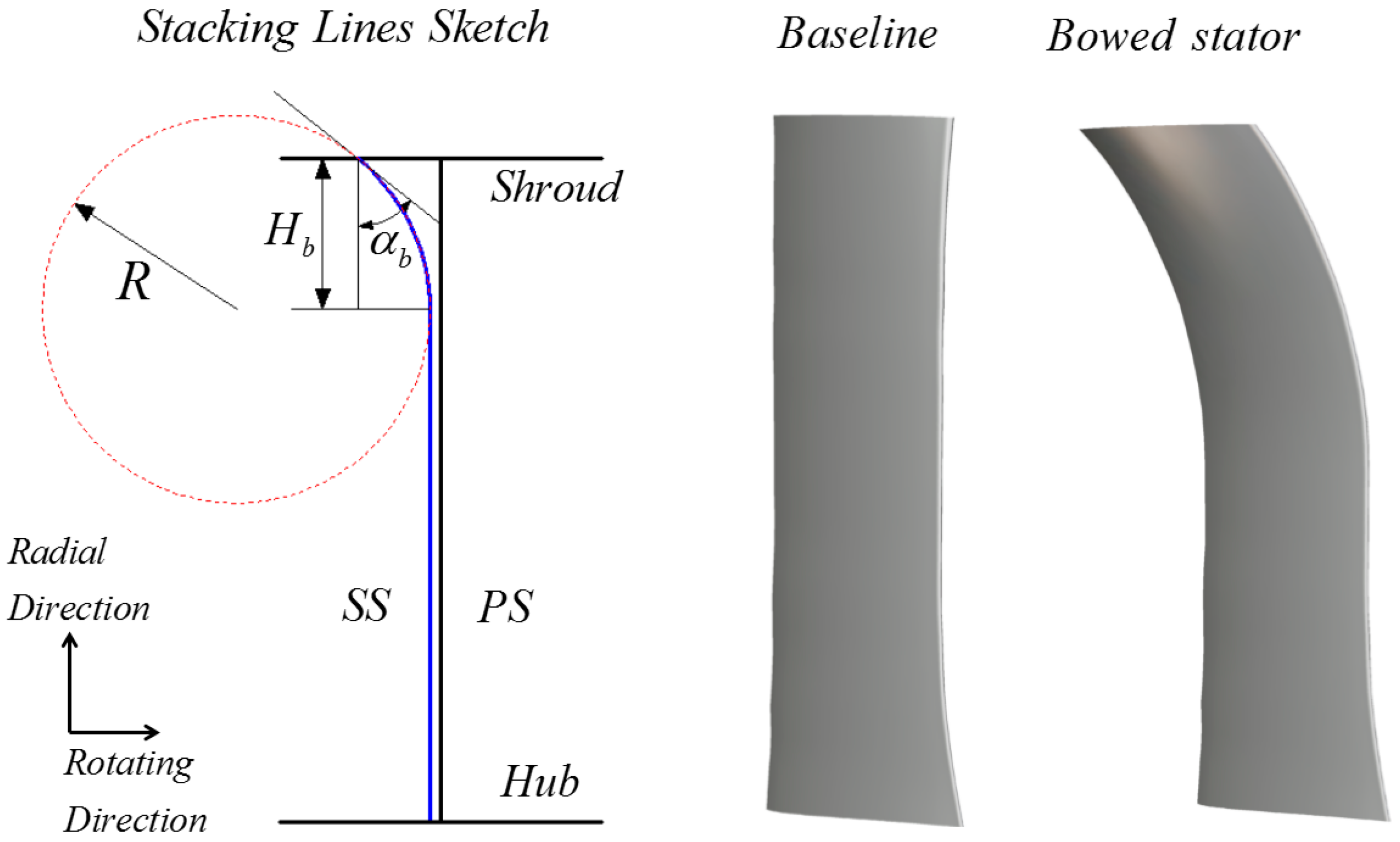
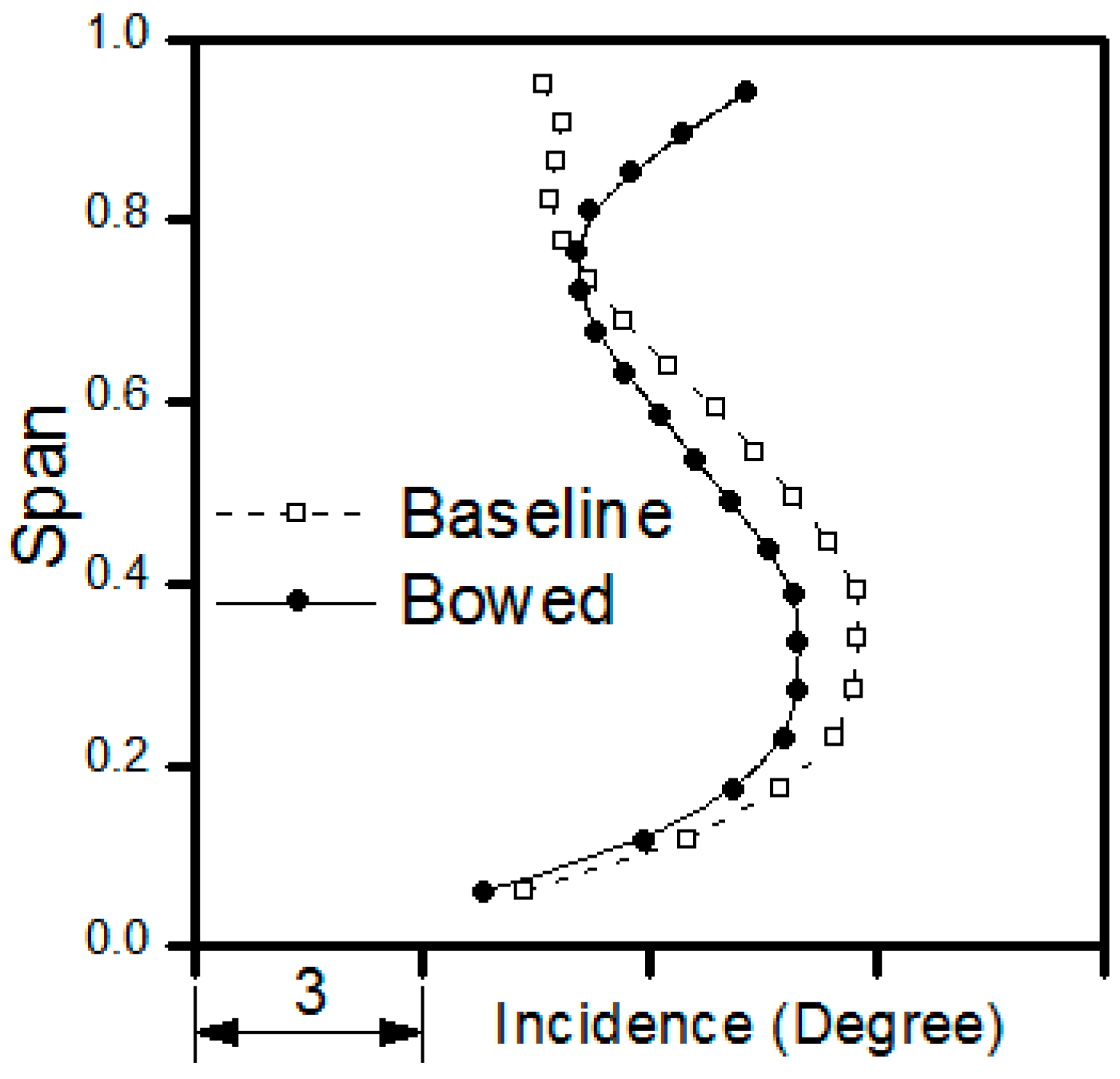
In this section, three-dimensional redesign strategies are introduced to gain aerodynamic performance improvements, which will be implemented in the next upgrade version of this type of compressor.
The previously shown results indicate that stator 5 is the main contradiction for aerodynamic improvement. The total pressure ratio of the last stage is approximately 1.25. The blade loading diffusion factor of stator 5 is approximately 0.46, with a typical subsonic inlet Mach number of 0.48. In this paper, upgrades are mainly made at the last stator. Various three-dimensional blading techniques, including bow, leading edge re-camber (LER) and re-solidity, are adopted in the aerodynamic redesign of stator 5.
To verify the effect of the redesign on the entire machine, the complete redesign process of stator 5 is incorporated with the multi-stage CFD methods, which is different from many redesigns of isolated or part-stage blade rows. Moreover, the newly developed in-house 3-D blade toolkit “NT-Blade” is employed to modify the redesigned blade geometry.

5.1. Bow

To explore the potential of the aerodynamic improvements of a radially stacked straight blade of the baseline, the 3-D blade bow design technique is first employed as the redesign strategy of stator 5. A positive bow is defined as a positive lean angle at the hub and a negative lean angle at the shroud in comparison with a normal, radially stacked straight blade [18]. It is well acknowledged that the bow is broadly adopted to eliminate corner stall in compressor vanes [17,18]. The bow induces radial forces on the fluids and results in shifting the fluids from the end walls to the midspan, which can reduce endwall loading and postpone the tendency towards corner stall. However, there are still no recognized, well-established bow criteria in the 3-D blade design of compressors that lead to performance benefits, mainly because different compressors are dominated by different flow controlling mechanisms between the endwall and mainstream regions [21].
It is found that the symmetric positive hub and tip bow type applied by many researchers to eliminate endwall corner stall does not lead to a performance improvement for the compressor in this research. This is mainly because the separation in stator 5 of this research is mainstream dominated instead of endwall dominated. The iso-surface of the axial velocity (−1 m/s) of stator 5 is shown in Figure 10, and the blue zones represent the low-momentum fluids, which demonstrate that the flow separation in stator 5 of the baseline is mainstream dominated. The symmetric bow types off-load the endwall region and also increase the secondary flow to the mainstream, which may migrate the low-momentum fluids to a larger region along the span, resulting in poorer flow conditions. Additionally, the results of Figure 10 correspond to the near stall point marked in Figure 4.
Considering that the loss mechanism is mainstream dominated, to suppress the migration of low-momentum fluids and improve the high loss region with high-momentum fluids, a compromise is applied as the redesign principle to implement the bow strategy. A dramatically asymmetric bow configuration is applied in this paper, as shown in Figure 11. In the 50%–100% span of the tip region, a circular arc stacking line is adopted. The parameters of bow height Hb and bow angle αb are applied to describe the bowed configuration. Providing enough radial force in the tip, a large circumferential displacement and 50% spanwise range of stacking (Hb = 0.5span, αb = 40°) are applied in the tip region. These are expected to improve the low-momentum fluid region (in the 15%–60% span) with the upper high-momentum fluids.
The flows shifting from the tip to the hub along the span is evident in Figure 12, where the pitch-averaged inlet axial velocity profile of the bowed stator 5 becomes much more uniform compared with the baseline.
The iso-surface of the axial velocity (−1 m/s) of bowed stator 5 in Figure 13 shows that the low-momentum fluid zone near the trailing edge at the middle span disappeared compared to that of the baseline, as shown in Figure 10.
Figure 14 demonstrates the relative Mach number and streamlines at the 35% span of the baseline and bowed stator 5. Compared with the baseline, the separations on the suction side completely vanished. The previously shown results show that the bow configuration helped to effectively improve the mainstream dominated low-momentum region.

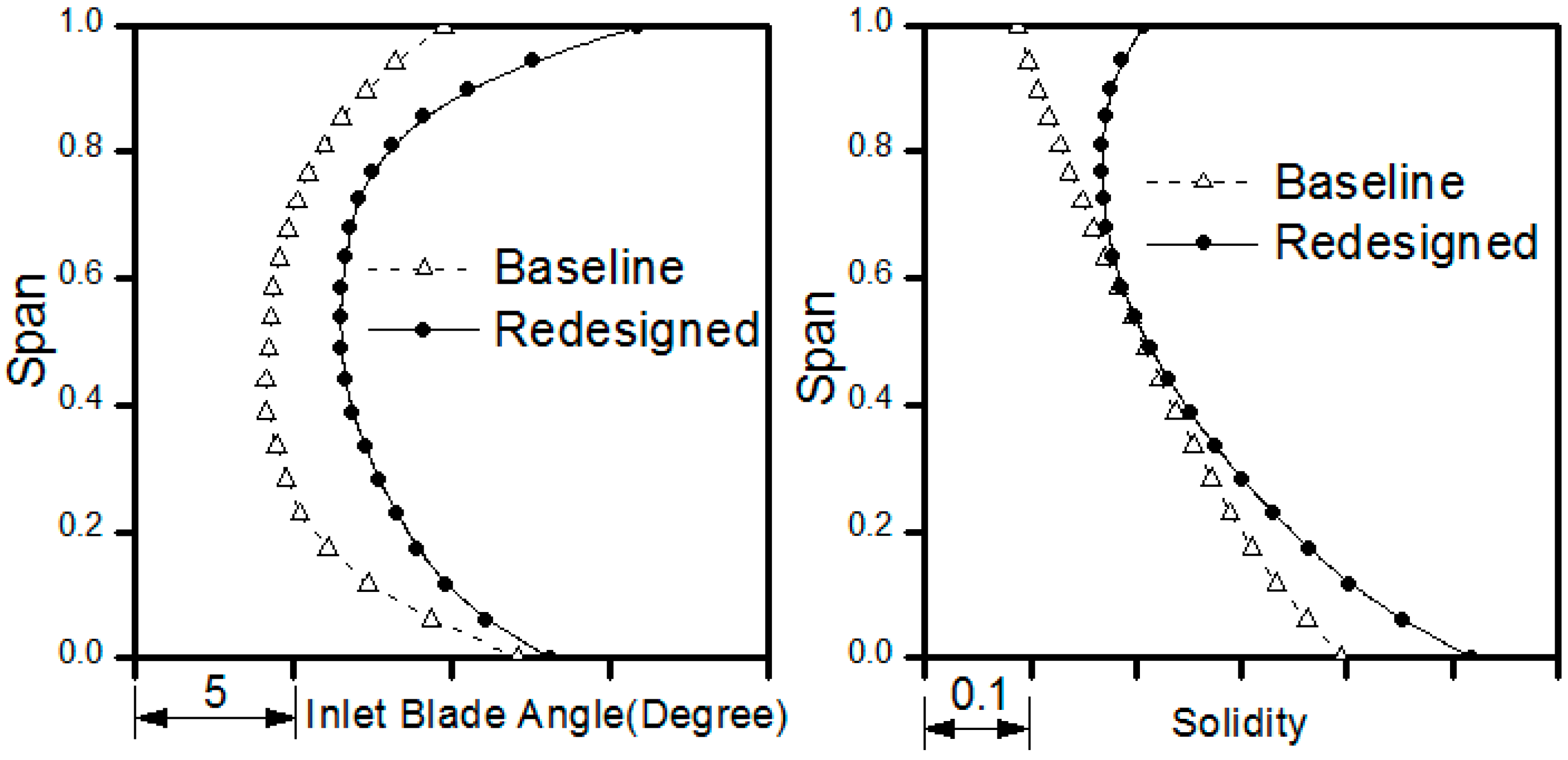
5.2. LER & Re-Solidity

According to previous aerodynamic analyses, the last stator of the baseline compressor operates at much higher unsatisfied incidences along the full span. Moreover, a larger incidence at the tip region was introduced by the dramatically asymmetric tip bow, and the high loss region in the middle span could not be completely eliminated by only applying the bow, as shown in Figure 15. To gain more performance improvement, other 3-D design methods, including LER and re-solidity, were added to the final redesigned strategy incorporated with the bow configuration.
LER alters the inlet blade angle in the partial chordwise range while maintaining the outlet blade angle to align the leading edge towards the flow direction. An increased incidence is introduced by the strong tip bow and high loss middle region, so the middle span and tip span regions are provided with larger inlet blade angles to reduce the high incidence, as demonstrated in Figure 16. Simultaneously, the pressure rise capability depends on both the incidence and solidity, especially for the endwall regions. Re-solidity is defined in this research as altering the solidity by changing the chord length while maintaining the thickness distribution. To prevent the tip and hub region flows from separation, the solidities in the endwall regions are increased, as illustrated in Figure 16. Additionally, the spanwise distribution of the solidity and inlet metal angle are parameterized using cubic spline curves.
Multi-stage CFD computations were conducted to evaluate the redesigned version, which applied the strong tip bow incorporated with LER and re-solidity. Figure 17 compares the incidence profiles between the baseline and redesigned stator 5 at the near stall points. The high incidence at the middle span was reduced by approximately three degrees, and the large inlet blade angle that increased in the tip region and that was introduced by re-camber prevented the strong tip bow from developing high incidence. A more reasonable spanwise incidence distribution and uniform loading, as well as the solidity redistribution, led to a significant loss reduction and performance improvement, as depicted in Figure 18. The total pressure loss of each S1 stream surface is defined as:
L o s s = P t i n P t o u t P t i n P s i n
where Ptin and Psin respectively denote the pitch-average total pressure and static pressure of each S1 stream surface leading edge (a short distance upstream blade). Ptout denotes the pitch-average total pressure of each S1 stream surface trailing edge (a short distance downstream blade).
To further substantiate the redesign effects, the total pressure contours downstream of the baseline and redesigned stator 5 at the near stall points are shown in Figure 19. Compared with the baseline, the high loss in the middle and lower spans are significantly reduced in the redesigned version. The iso-surface of the axial velocity (−1 m/s) of stator 5 in Figure 20 shows that the low-momentum fluid zone is reduced significantly compared with that of the baseline. The previously shown results illustrate that the bow configuration and the LER and re-solidity applied in the redesigned version help to effectively improve the low-momentum region.
Finally, the overall performances are identified, as presented in Figure 21. Compared with the baseline, the three-dimensional redesign contributes an approximate 13% stall margin increase to the redesigned version. The stall margin is defined as follows:
S t a l l M a r g i n = ε N S ε D × m D m N S
where ε D and ε N S denote the total pressure ratio at the design point and at the near stall point, respectively, and m D and m N S denote the corrected mass flow rate at the design point and at the near stall point, respectively.
Furthermore, the redesigned version also maintains the efficiency at the design point while providing a sufficient operating range, which proves that the redesign strategies are effective.

6. Conclusions

In this paper, the three-dimensional redesign of a stator blade is conducted in a 5-stage axial compressor with multi-stage CFD methods. The conclusions are as follows:
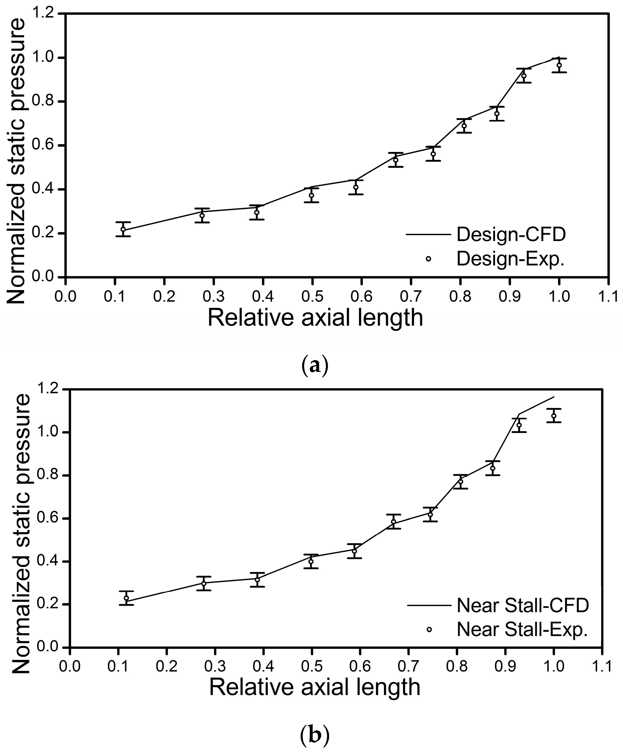
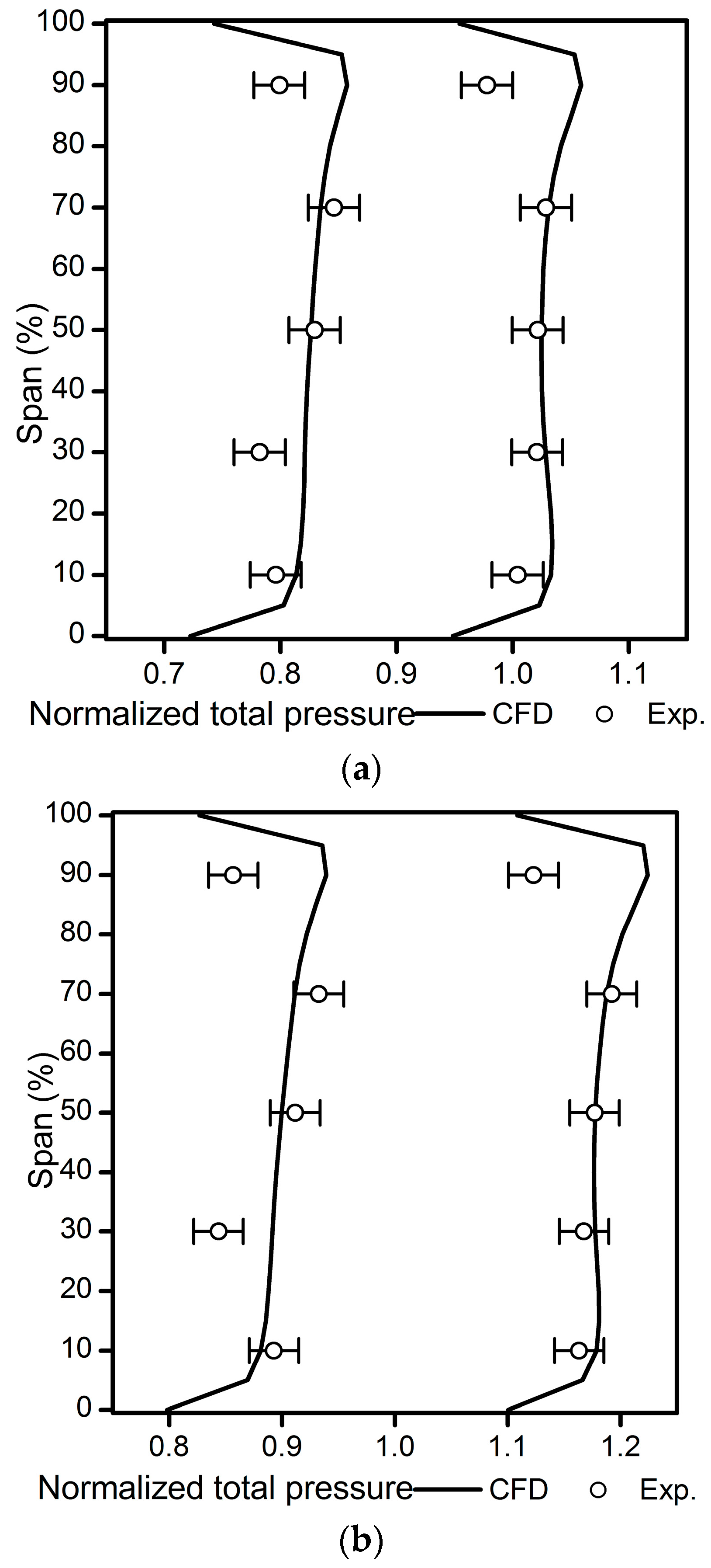
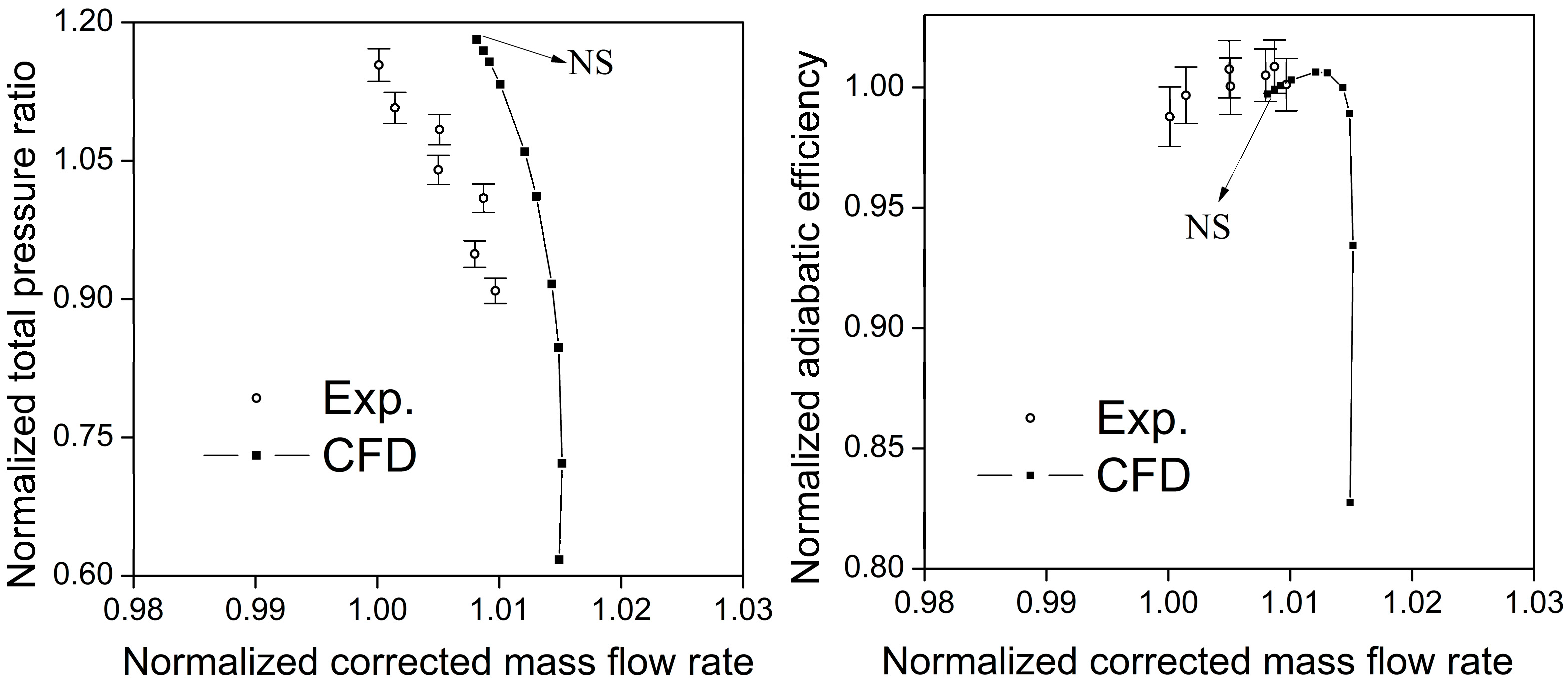
  • Validation with the full-scale test data is conducted for the multi-stage CFD methods prior to redesign. The multi-stage CFD methods applied in this research predict the overall performance quite well and also accurately capture the casing static pressure and stator leading edge total pressure profiles, both under design and off-design operating conditions.
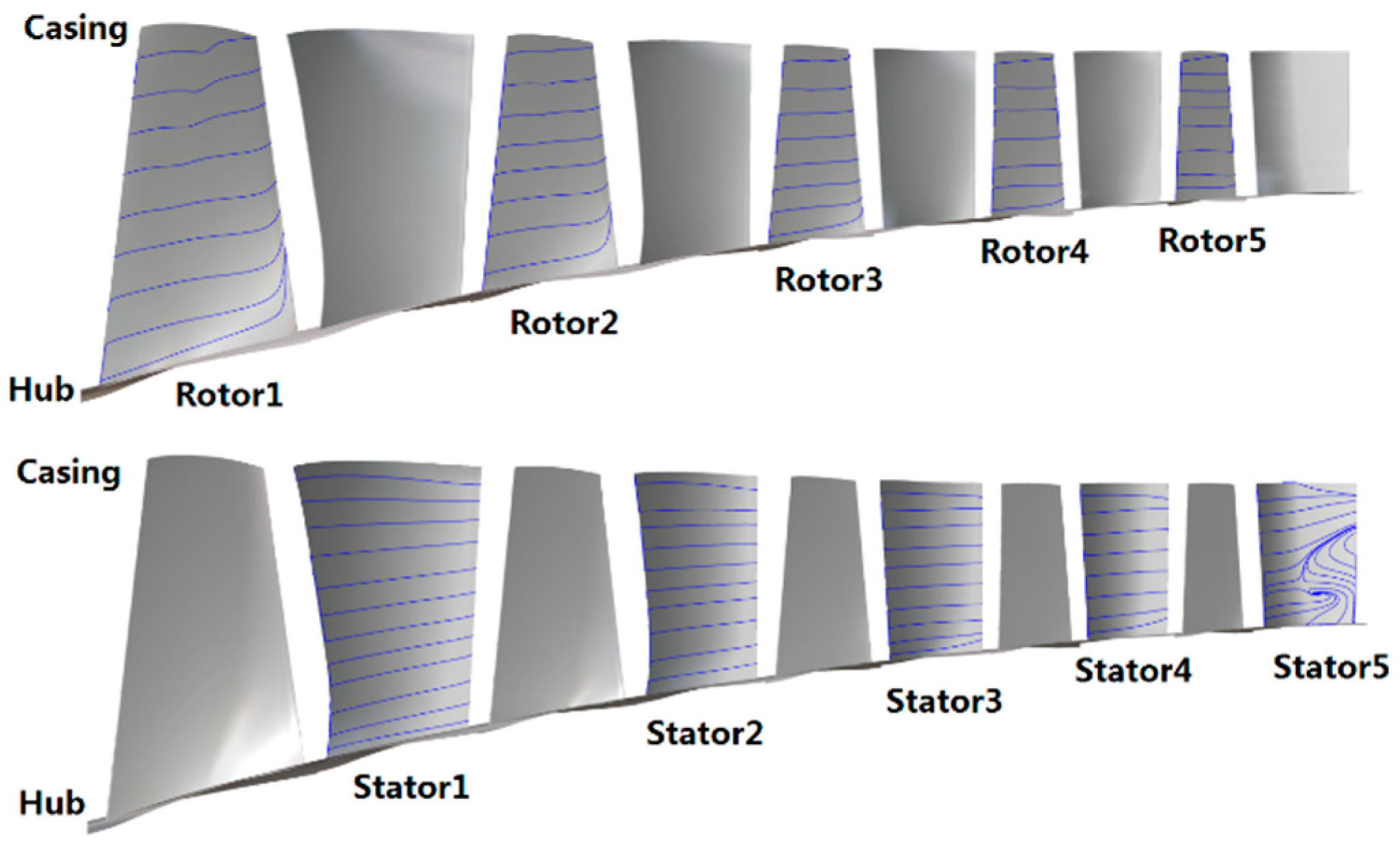
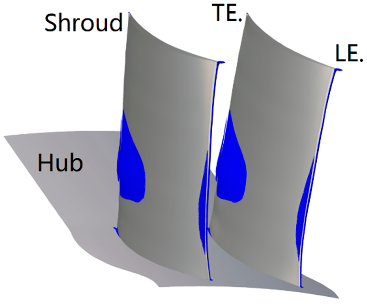
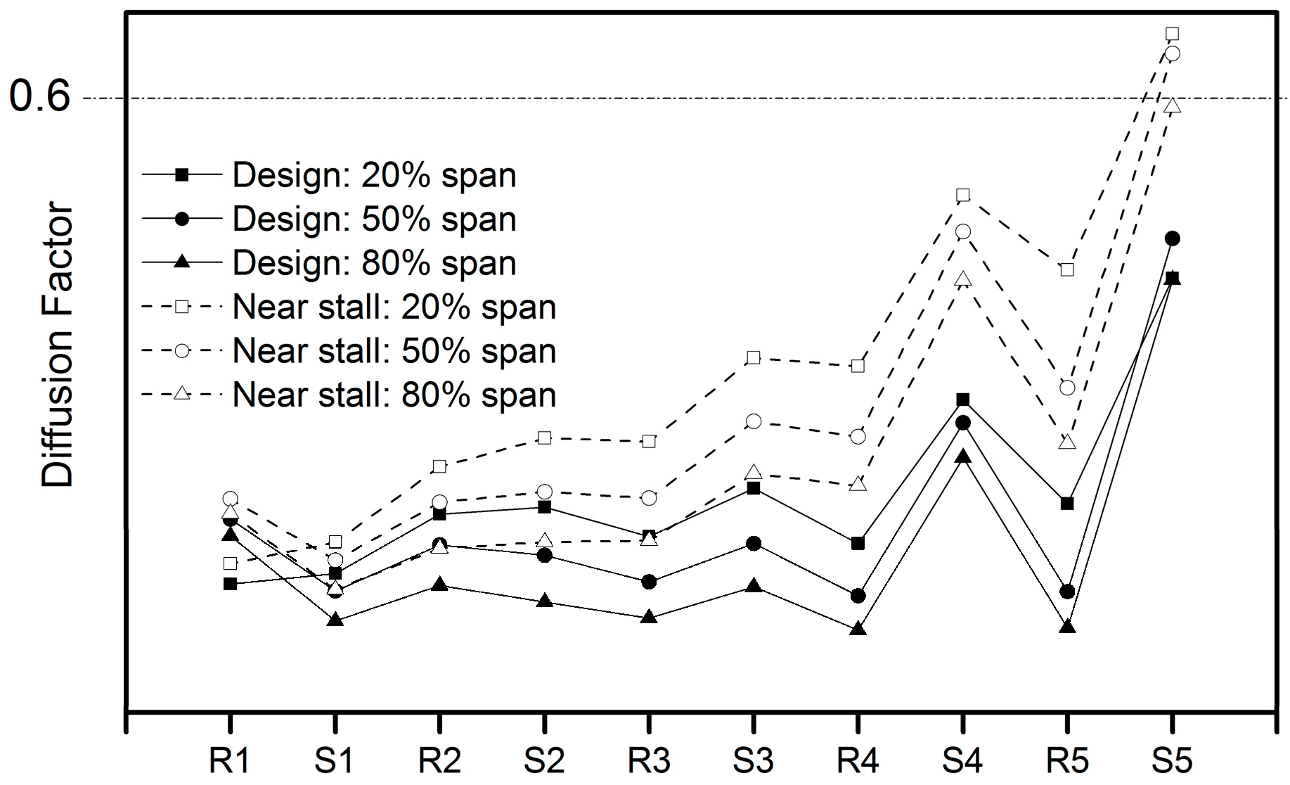
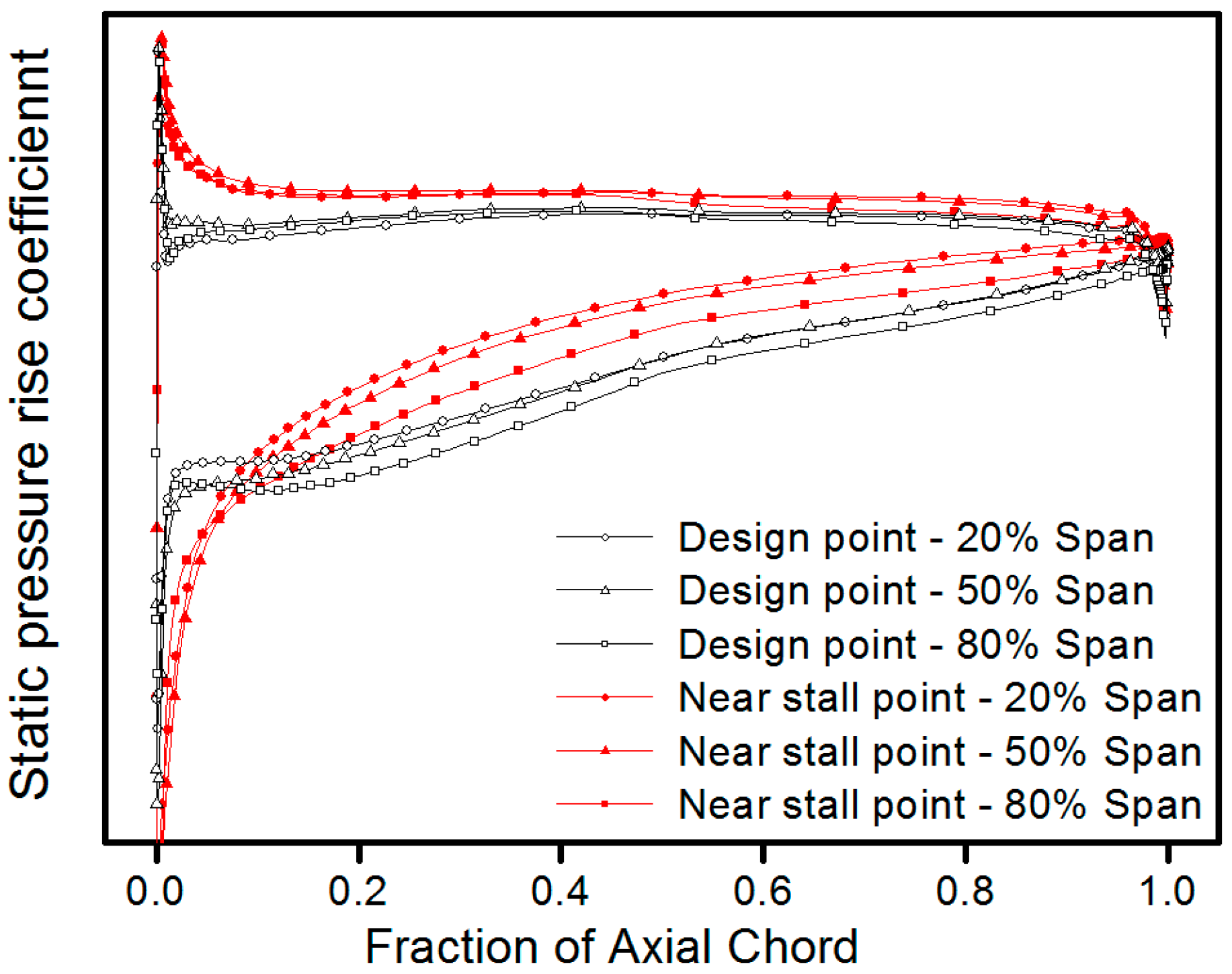
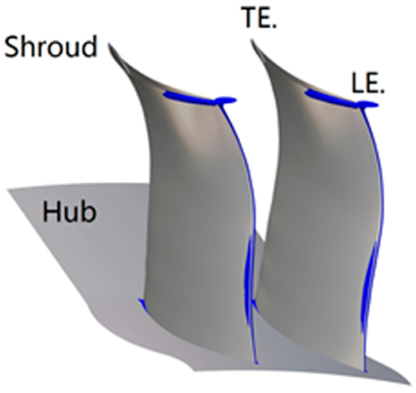
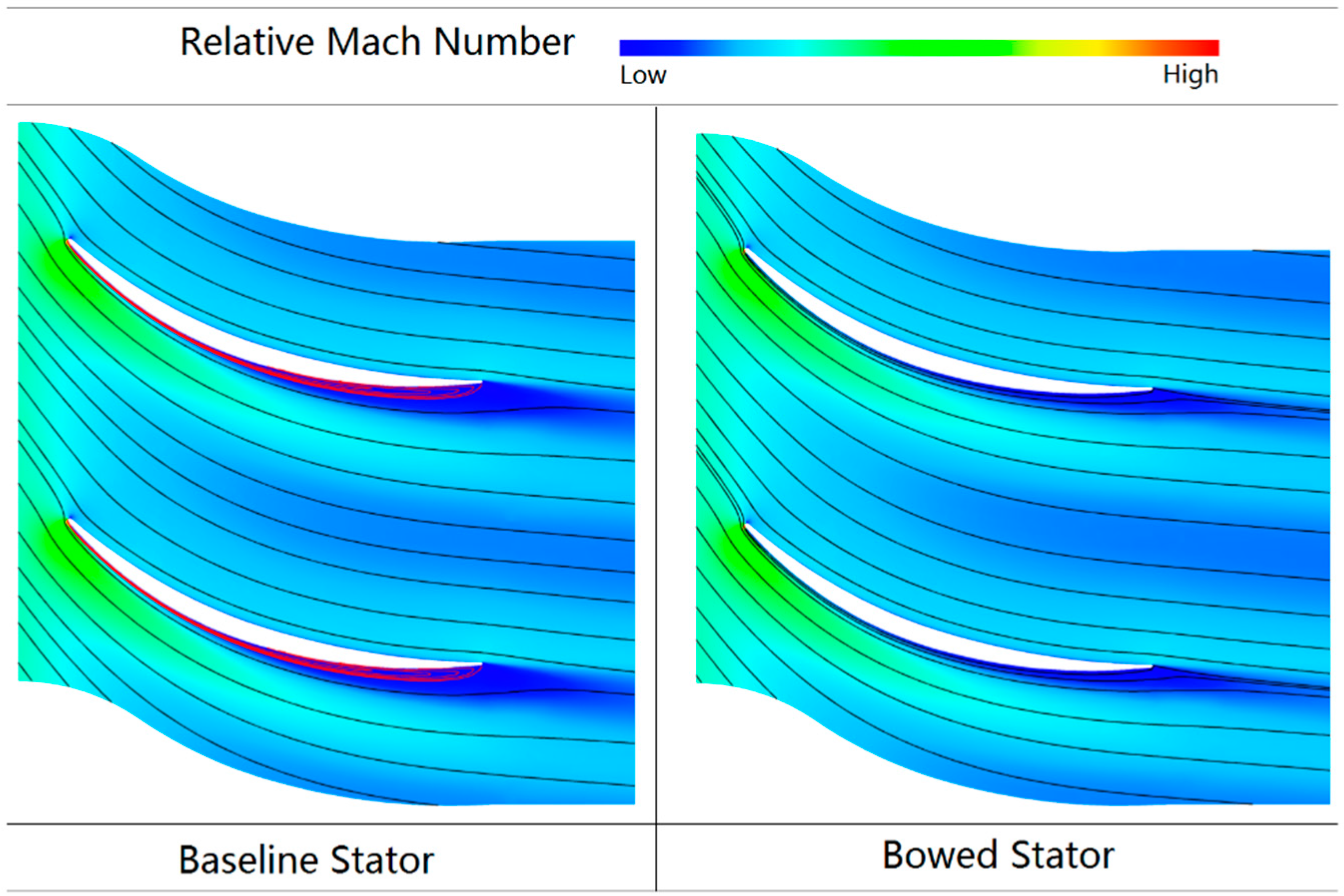
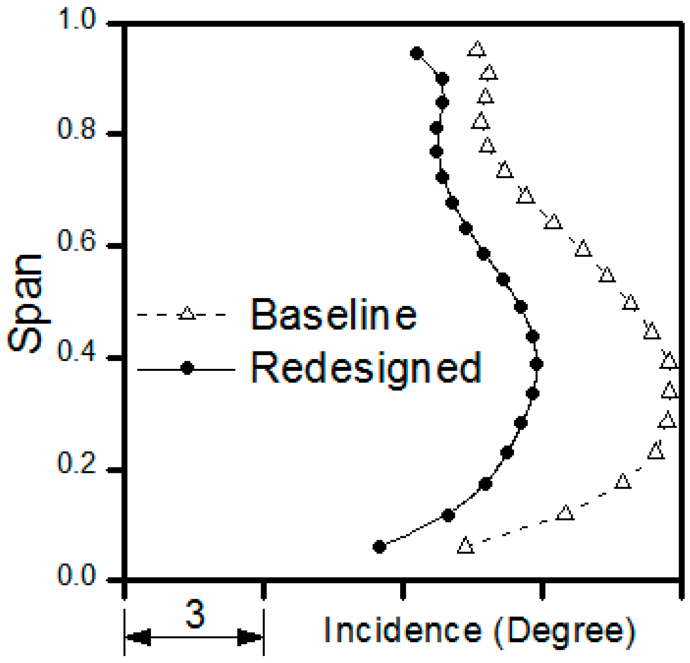
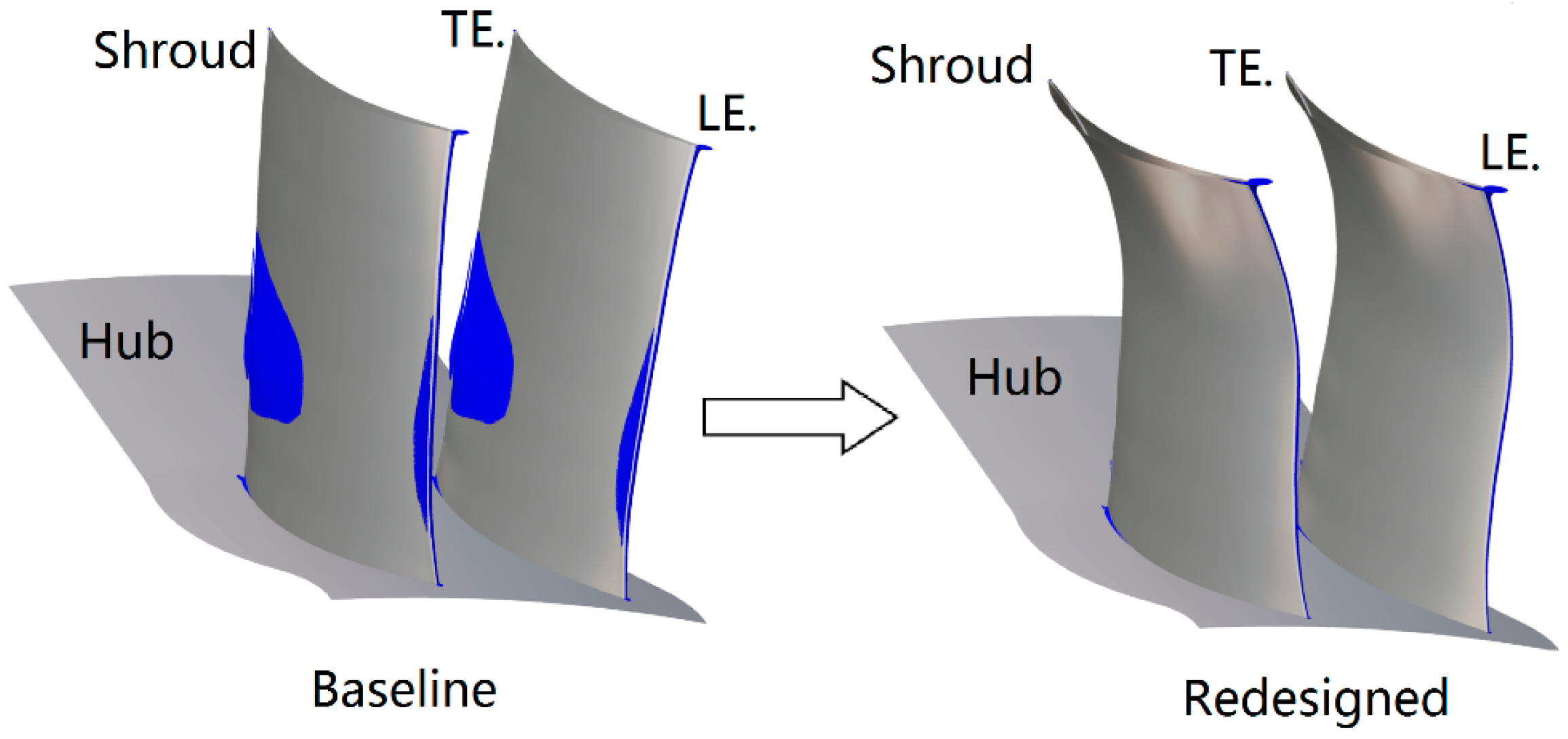
  • The detailed aerodynamic analysis indicates that a large separation exists in the suction side of the last stator, resulting in stall. Thus, the follow-up redesign focuses on the last stator.
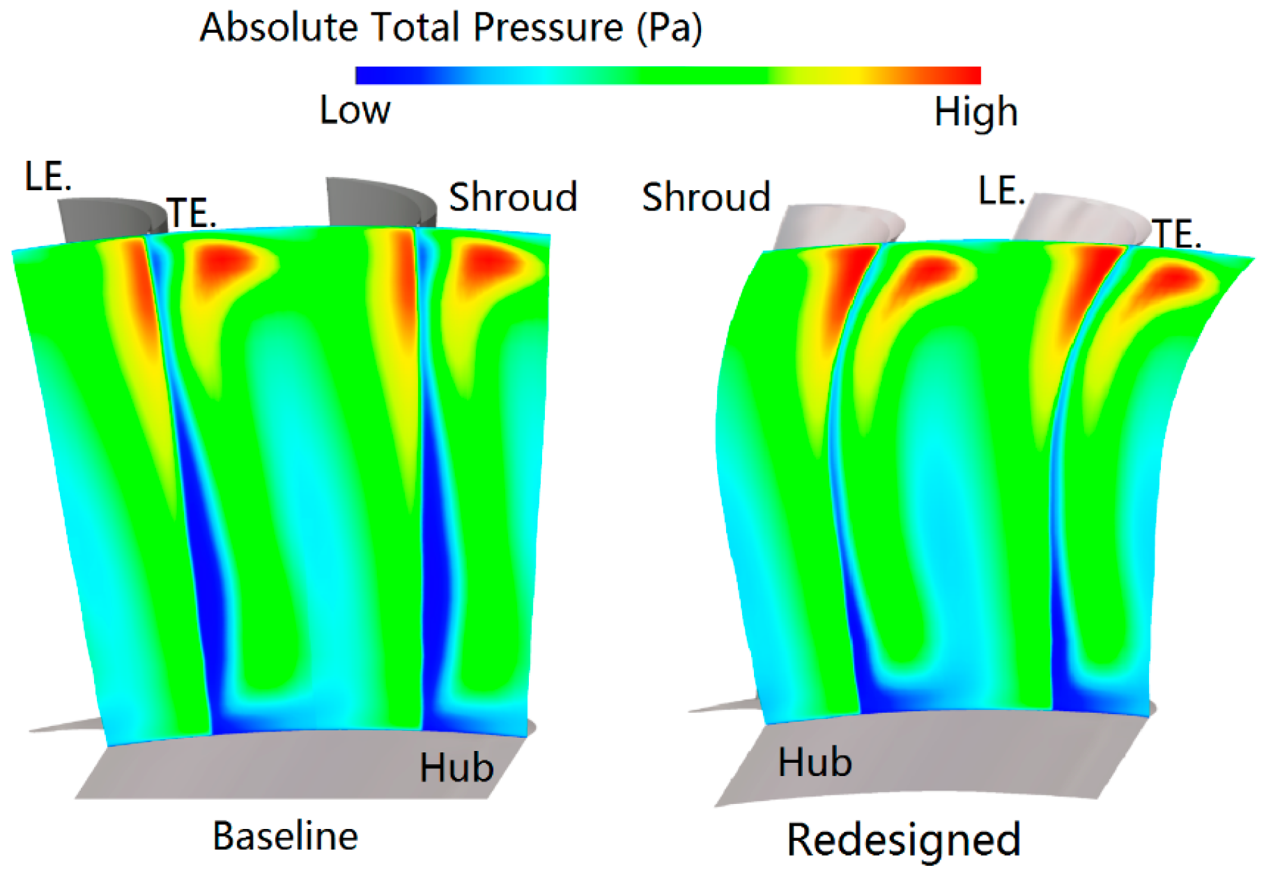
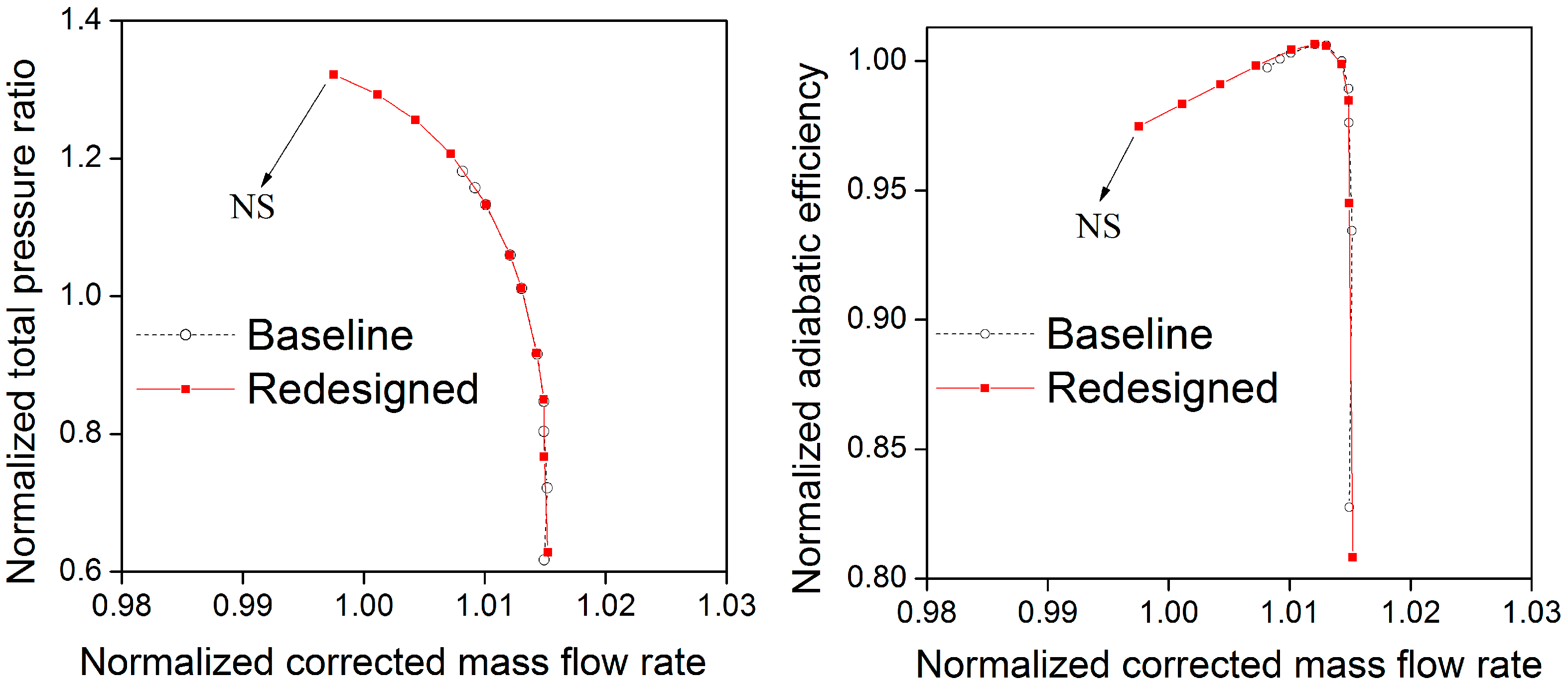
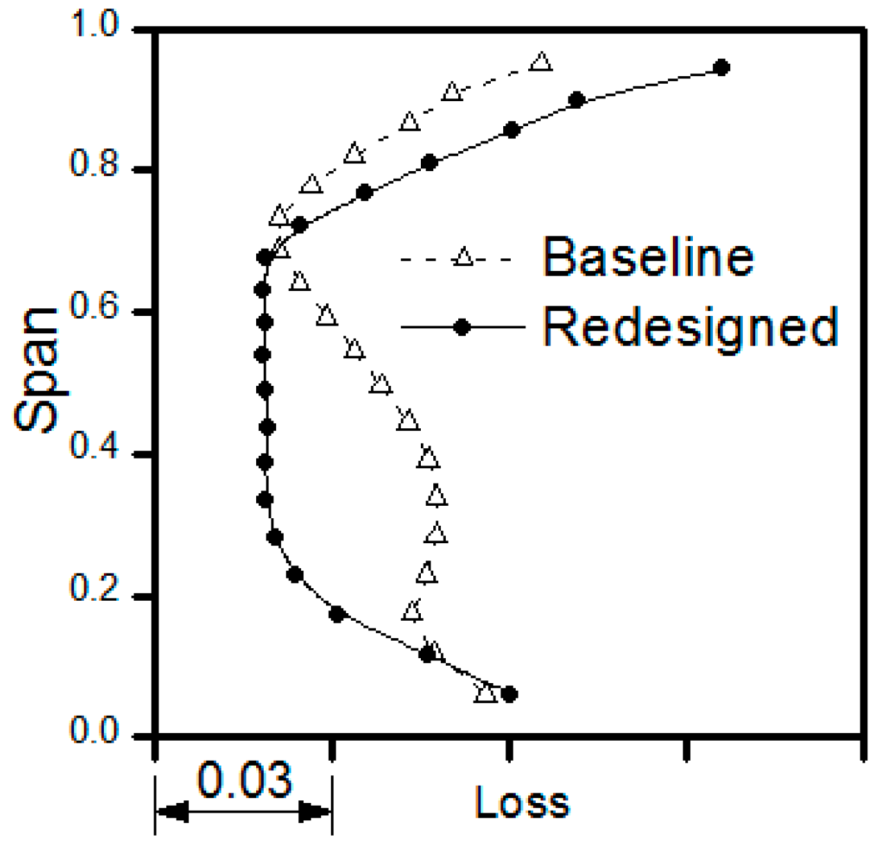
  • The mainstream flow separation dominates the loss, so a dramatically asymmetric positive bow incorporated with leading edge re-camber and re-solidity is applied for the redesigned version. The most significant achievement of the three-dimensional blade redesign in this research is the stall margin improvement, with a total 13% stall margin increase compared with the baseline, while maintaining efficiency at the design points.
This research explains the power of multi-stage CFD methods applied in the aerodynamic analysis and three-dimensional redesign of a modern highly loaded compressor in the multi-stage environment. The redesigning exploitation by bow, re-camber and re-solidity techniques provides various beneficial design philosophies of 3-D blading for the development of modern highly loaded compressors.

Acknowledgments

This work is supported by the Shenyang Engine Design and Research Institute (SEDRI), the Collaborative Innovation Center of Advanced Aero-Engine and the National Natural Science Foundation of China (Grant No. 51136003). The authors would like to thank SEDRI for permission to publish this paper.

Author Contributions

In this paper, Tao Ning developed the in-house 3-D blade toolkit “NT-Blade”, proposed the blade optimization method, performed the aerodynamic analysis and wrote the manuscript; Chun-Wei Gu and Wei-Dou Ni provided guidance for the blade optimization and polished the manuscript; Xiao-Tang Li and Tai-Qiu Liu conducted part of the experiments of the full-scale test rig.

Conflicts of Interest

The authors declare no conflict of interest.

Nomenclature

ANNsArtificial Neural Networks
ANSYS-CFXCFD Code by ANSYS
APNASACFD Code by NASA
BBEWBlended blade and endwall
CDAControlled Diffusion Airfoil
CFDComputational Fluid Dynamics
FEMFinite Element Method
IGVInlet Guided Vane
LELeading Edge
LERLeading Edge Re-camber
MCAMultiple Circular Arc
NASANational Aeronautics and Space Administration
Numeca-Fine/TurboCFD Code by Numeca
PSPressure Surface
RANSReynolds-Averaged Navier-Stokes
SEDRIShenyang Engine Design and Research Institute
SSSuction Side
TETrailing Edge
mDCorrected mass flow rate at the design point
mNSCorrected mass flow rate at the near stall point
PtinInlet pitch-average total pressure
PtoutOutlet pitch-average total pressure
PsinInlet pitch-average static pressure
y+Dimensionless distance of the first grid node off the wall, y + = ρ u τ y w a l l / μ
εDTotal pressure ratio at the design point
εNSTotal pressure ratio at the near stall point

References

  1. Denton, J.D. Throughflow calculations for transonic axial flow turbines. J. Eng. Power 1978, 100, 212–218. [Google Scholar] [CrossRef]
  2. Hirsch, C.; Denton, J.D. Through-flow calculations in axial turbomachines. Advisory Group for Aeronau-tical Research and Development (AGARD); Advisory Report, No.175. 1981. [Google Scholar]
  3. Hale, A.A.; Davis, M.W.; Kneile, K.R. Turbine engine analysis compressor code: TEACC—Part I: Technical approach and steady results. In Proceedings of the AIAA 32nd Aerospace Sciences Meeting, Reno, NV, USA, 10–13 January 1994.
  4. Adamczyk, J.J. Model Equation for Simulating Flows in Multistage Turbomachinery. In Proceedings of the 30th International Gas Turbine Conference and Exhibit, Houston, TX, USA, 1985; American Society of Mechanical Engineers (ASME): New York, NY, USA, 1985. [Google Scholar]
  5. Adamczyk, J.J.; Mulac, R.A.; Celestina, M.L. A model for closing the inviscid form of the average-passage equation system. ASME J. Turbomach. 1986, 108, 180–186. [Google Scholar] [CrossRef]
  6. Adamczyk, J.J.; Celestina, M.L.; Beach, T.A.; Barnett, M. Simulation of three-dimensional viscous flow within a multistage turbine. ASME J. Turbomach. 1990, 112, 370–376. [Google Scholar] [CrossRef]
  7. Adamczyk, J.J. Aerodynamic analysis of multistage turbomachinery flows in support of aerodynamic design. ASME J. Turbomach. 2000, 122, 189–217. [Google Scholar] [CrossRef]
  8. Mansour, M.; Hingorani, S.; Dong, Y. A new multistage axial compressor designed with the APNASA multistage CFD code: Part 1—Code calibration. In Proceedings of the ASME Turbo 2001: Power for Land, Sea, and Air, New Orleans, LA, USA, 4–7 June 2001; American Society of Mechanical Engineers (ASME): New York, NY, USA, 2001. [Google Scholar]
  9. Dong, Y.; Mansour, M.; Hingorani, S.; Hayes, J. A new multistage axial compressor designed with the APNASA multistage CFD code: Part 2—Application to a new compressor design. In Proceedings of the ASME Turbo Expo 2001: Power for Land, Sea, and Air, New Orleans, LA, USA, 4–7 June 2001; American Society of Mechanical Engineers (ASME): New York, NY, USA, 2001. [Google Scholar]
  10. Wellborn, S.R.; Delaney, R.A. Redesign of a 12-stage axial-flow compressor using multistage CFD. In Proceedings of the ASME Turbo Expo 2001: Power for Land, Sea, and Air, New Orleans, LA, USA, 4–7 June 2001; American Society of Mechanical Engineers (ASME): New York, NY, USA, 2001. [Google Scholar]
  11. Mansour, M.L.; Gunaraj, J.; Goswami, S. Validation of steady average-passage and mixing plane CFD approaches for the performance prediction of a modern gas turbine multistage axial compressor. In Proceedings of the ASME Turbo Expo 2008: Power for Land, Sea, and Air, Berlin, Germany, 9–13 June 2008; American Society of Mechanical Engineers (ASME): New York, NY, USA, 2008; Volume 6, pp. 393–402. [Google Scholar]
  12. Belamri, T.; Galpin, P.; Braune, A.; Cornelius, C. CFD analysis of a 15 stage axial compressor: Part I—Methods. In Proceedings of the ASME Turbo Expo 2005: Power for Land, Sea, and Air, Reno-Tahoe, NV, USA, 6–9 June 2005; American Society of Mechanical Engineers (ASME): New York, NY, USA, 2005; Volume 6 (Part B), pp. 1001–1008. [Google Scholar]
  13. Belamri, T.; Galpin, P.; Braune, A.; Cornelius, C. CFD analysis of a 15 stage axial compressor: Part II—Results. In Proceedings of the ASME Turbo Expo 2005: Power for Land, Sea, and Air, Reno-Tahoe, NV, USA, 6–9 June 2005; American Society of Mechanical Engineers (ASME): New York, NY, USA, 2005; Volume 6 (Part B), pp. 1009–1017. [Google Scholar]
  14. Terauchi, K.; Kariya, D.; Maeda, S.; Yoshiura, K. Redesign of an 11-stage axial compressor for industrial gas turbine. In Proceedings of the ASME Turbo Expo 2005—Gas Turbine Technology: Focus for the Future, Reno-Tahoe, NV, USA, 6–9 June 2005; American Society of Mechanical Engineers (ASME): New York, NY, USA, 2005; Volume 6 (Part A), pp. 261–267. [Google Scholar]
  15. Ikeguchi, T.; Matsuoka, A.; Sakai, Y.; Sakano, Y.; Yoshiura, K. Design and development of a 14-stage axial compressor for industrial gas turbine. In Proceedings of the ASME Turbo Expo 2012: Turbine Technical Conference and Exposition, Copenhagen, Denmark, 11–15 June 2012; American Society of Mechanical Engineers (ASME): New York, NY, USA, 2012; Volume 8, pp. 125–134. [Google Scholar]
  16. Brilliant, L.; Burger, G.; Balamucki, S.; Dong, Y.; Lejambre, C. Application of multistage CFD analysis to low pressure compressor design. In Proceedings of the ASME Turbo Expo 2004, Vienna, Austria, 14–17 June 2004; American Society of Mechanical Engineers (ASME): New York, NY, USA, 2004; Volume 5, pp. 645–653. [Google Scholar]
  17. Ren, X.D.; Xu, K.; Shyy, W.; Gu, C.W. A multi-dimensional high-order discontinuous Galerkin method based on gas kinetic. J. Comput. Phys. 2015, 292, 176–193. [Google Scholar] [CrossRef]
  18. Ren, X.D.; Gu, C.W. Investigation of compressor tip clearance flow based on the discontinuous galerkin methods. In Proceedings of the ASME Turbo Expo 2013: Turbine Technical Conference and Exposition, San Antonio, TX, USA, 3–7 June 2013; American Society of Mechanical Engineers (ASME): New York, NY, USA, 2013. [Google Scholar]
  19. Ren, X.D.; Gu, C.W. Application of a discontinuous Galerkin method on the compressible flow in the transonic axial compressor. Appl. Therm. Eng. 2015, 93, 707–717. [Google Scholar] [CrossRef]
  20. Weingold, H.; Neubert, R.; Behlke, R.; Potter, G. Bowed stators: An example of CFD applied to improve multistage compressor efficiency. ASME J. Turbomach. 1997, 119, 161–168. [Google Scholar] [CrossRef]
  21. Fischer, A.; Riess, W.; Seume, J.R. Performance of strongly bowed stators in a four-stage high-speed compressor. ASME J. Turbomach. 2004, 126, 333–338. [Google Scholar] [CrossRef]
  22. Denton, J.; Xu, L. The exploitation of three-dimensional flow in turbomachinery design. Proc. Inst. Mech. Eng. C 1998, 213, 125–137. [Google Scholar] [CrossRef]
  23. Gallimore, S.J.; Bolger, J.J.; Cumpsty, N.A. The use of sweep and dihedral in multistage axial flow compressor blading, Part 2: Low and high speed designs and test verification. ASME J. Turbomach. 2002, 124, 533–541. [Google Scholar] [CrossRef]
  24. Ji, L.C.; Tian, Y.; Li, W.; Yi, W.; Wen, Q. Numerical studies on improving performance of rotor-67 by blended blade and endwall technique. In Proceedings of the ASME Turbo Expo 2012: Turbine Technical Conference and Exposition, Copenhagen, Denmark, 11–15 June 2012; American Society of Mechanical Engineers (ASME): New York, NY, USA, 2012; Volume 8, pp. 135–145. [Google Scholar]
  25. Denton, J.D. Some limitations of turbomachinery CFD. In Proceedings of the ASME Turbo 2010: Power for Land, Sea, and Air, Glasgow, UK, 14–18 June 2010; American Society of Mechanical Engineers (ASME): New York, NY, USA, 2010; Volume 7, pp. 735–745. [Google Scholar]
  26. Pierret, S.; Coelho, R.F.; Kato, H. Multidisciplinary and multiple operating points shape optimization of three-dimensional compressor blades. Struct. Multidiscip. Optim. 2007, 33, 61–70. [Google Scholar] [CrossRef]
  27. Zhao, Q.J.; Zhou, X.Y.; Xiang, X.Y. Multi-Objective optimization of groove casing treatment in a transonic compressor. Proc. Inst. Mech. Eng. A 2014, 228, 626–637. [Google Scholar] [CrossRef]
  28. Zhang, Y.Y.; Huang, D.G.; Sun, X.J.; Wu, G.Q. Exploration in optimal design of an airfoil with a leading edge rotating cylinder. J. Therm. Sci. 2010, 19, 318–325. [Google Scholar] [CrossRef]
  29. NUMECA International. Available online: http: //www.numeca.com (accessed on 6 June 2015).
  30. Spalart, P.R.; Allmaras, S.R. A one equation turbulence model for aerodynamic flows. Rech. Aerosp. 1994, 1, 5–21. [Google Scholar]
Figure 1. Overall configuration of the compressor.
Energies 09 00296 g001
Figure 2. Typical mesh topology.
Energies 09 00296 g002
Figure 3. Mesh for the CFD computations.
Energies 09 00296 g003
Figure 4. Measured and predicted overall performance. NS: Near Stall.
Energies 09 00296 g004
Figure 5. Measured and predicted casing static pressure. (a) Design point; (b) Near stall point. Exp.: Experiment.
Energies 09 00296 g005
Figure 6. Measured and predicted total pressure profiles at the leading edges of stator 4 and stator 5. (a) Design point of stator 4 and stator 5; (b) Near stall point of stator 4 and stator 5.
Energies 09 00296 g006
Figure 7. Limiting streamlines on the suction side of each blade at the near stall point.
Energies 09 00296 g007
Figure 8. Streamwise diffusion factor distributions of each row.
Energies 09 00296 g008
Figure 9. Surface static pressure rise coefficient distributions at the 20%, 50% and 80% spans of stator 5.
Energies 09 00296 g009
Figure 10. Iso-surface of the axial velocity (−1 m/s) for stator 5 of the baseline (near the stall points). TE.: trailing edge; LE.: leading edge.
Energies 09 00296 g010
Figure 11. Stacking lines sketch and blade shapes of stator 5. SS: suction side; PS: pressure side.
Energies 09 00296 g011
Figure 12. Spanwise distributions of the inlet axial velocity (near the stall points).
Energies 09 00296 g012
Figure 13. Iso-surface of the axial velocity (−1 m/s) for the bowed stator 5 (near the stall points).
Energies 09 00296 g013
Figure 14. Relative Mach number contours and streamlines at the 35% span of stator 5 (near the stall points).
Energies 09 00296 g014
Figure 15. Spanwise distributions of the incidence at the design point.
Energies 09 00296 g015
Figure 16. Inlet blade angle and solidity profiles of the baseline and redesigned stator 5.
Energies 09 00296 g016
Figure 17. Spanwise distributions of the incidence for the baseline and redesigned stator 5 (near the stall points).
Energies 09 00296 g017
Figure 18. Loss profiles of the baseline and redesigned stator 5 (near the stall points).
Energies 09 00296 g018
Figure 19. Total pressure contours downstream of the baseline and redesigned stator 5 (near the stall points).
Energies 09 00296 g019
Figure 20. Iso-surface of the axial velocity (−1 m/s) for the baseline and redesigned stator 5 (near the stall points).
Energies 09 00296 g020
Figure 21. Overall performances.
Energies 09 00296 g021

