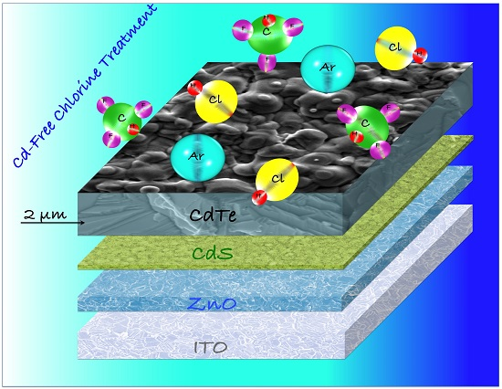
3.1. The Chlorine Treatment
An important step in CdTe-based solar cell fabrication is the treatment of the CdTe film in the presence of chlorine, at a temperature of about 670 K. It is generally accepted by the scientific community that the chlorine-treatment increases the grain size of the CdTe film, improves the quality of the grain boundaries and promotes an intermixing of CdS and CdTe layers at their interface. Chlorine is normally supplied by depositing chlorine salts in the form of thin film on top of the CdTe layer. These salts include CdCl
2, MgCl
2, NaCl, and NH
4Cl [
24,
25,
26,
27,
28,
29]. Among them, the Cd-free salts have the great advantage of being much more environmentally sustainable than CdCl
2. An alternative way to carry out a Cd-free chlorine treatment of the CdTe film is to use as a halogen carrier gas capable of releasing chlorine or chlorine-containing radicals at the processing temperature. This typology of gases belongs to the chlorine-based Freon family or to the chlorine family itself (HCl, Cl
2,
etc.). Hydrochloric acid or chlorine are very aggressive gases and their utilization is a cause of instability to the system which makes the CdTe treatment extremely critical [
30,
31]. Romeo
et al. in 2006 [
32] proposed the alternative approach of using difluoro-chloro-methane (R-22) as the process gas. This treatment provides the same results as those achieved using CdCl
2 and solar cells with efficiencies higher than 15% have been produced using this technique. A great advantage of this method is the possibility of controlling the quantity of chlorine-based radicals on the CdTe surface by adjusting the pressure of the treatment atmosphere in the process chamber. Starting from 2011, the industrial utilization of R-22 has been banned in Europe because it is an ozone-depleting substance (ODS). For this reason, other chlorinated hydrocarbon, effective in treating CdTe and not considered ODS, were considered. Possible candidates have been identified among the liquid chlorinated hydrocarbons (LCHY). These materials are liquid at room temperature, easy to handle, and are not subject to any restriction, except for what concerns fire prevention. In the conditions at which treatment takes place, all of these substances are commonly characterized by the presence of hydrochloric acid as part of the LCHY dissociation. HCl itself was investigated as a treatment material and provided very similar results to those obtained with the LCHY. However, the presence of very aggressive species, such as HCl, makes the interaction with the surface of the CdTe film very difficult to control. To ensure a capability to completely control the system, fluorinated hydrocarbons (FLHY) are added to the chlorinated species in the process gas. Using this method, the desired condition for chlorine treatment was obtained and the R-22 results [
32] have been easily reproduced. The chlorine treatment is carried out in a quartz ampoule in which the sample is introduced. Firstly, the ampoule is evacuated using a rotary and turbo molecular pump system, reaching a vacuum of at least 1 × 10
−4 Pa. Then the ampoule is brought to a temperature between 620 K and 700 K. A controlled amount of chlorinated hydrocarbon is introduced into the ampoule and its pressure is measured through a “baratron”-type head and maintained between 50 Pa and 2 × 10
3 Pa.
The chlorinated hydrocarbons are liquid and the reaction chamber requires they be delivered in the form of a vapor. The LCHY, kept at room temperature, can be vaporized both by reducing the pressure in the reaction chamber or by passing an inert transporting gas through the LCHY ampoule. The inert gas flux and the pressure in the vaporization chamber must be controlled in order to have the right amount of hydrocarbon in the reaction chamber. The partial vapor pressure of the liquid hydrocarbon depends on the temperature of the vaporizer since it is determined by the liquid-vapor equilibrium. Moreover, a gas of the FLHY family, with partial pressure between 1 × 10⁴ Pa and 4 × 10⁴ Pa, can be mixed with a chlorinated one. An inert gas such as Ar can be added to this mixture of hydrocarbons with partial pressure ranging from 1 × 10⁴ Pa to 4 × 10⁴ Pa in order to reach a maximum total pressure of 5 × 10⁴ Pa. After the CdTe treatment, the gases that exit the quartz ampoule are composed of unreacted species and decomposition fragments. Since these products cannot be released directly into the environment, they must be treated with an abatement process, which releases only the inert transporting gas that can then be recycled. The byproducts of the reaction can be captured by passing them through an alkaline solution.
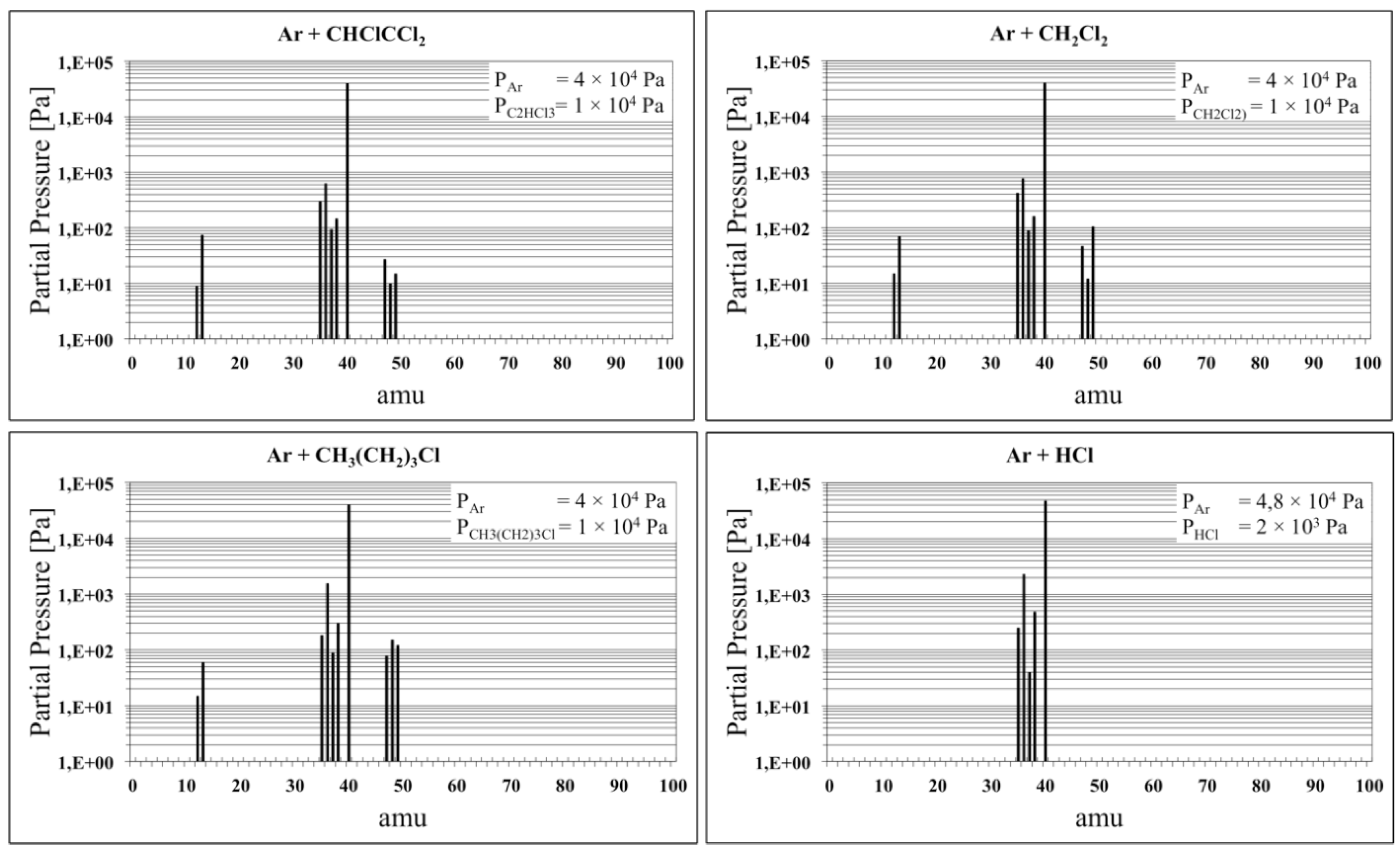
Among all the possible chlorinated hydrocarbons those that were tested are the following: 1-chlorobutane (CH3(CH2)3Cl), 1,1,2-trichloroethylene (CHClCCl2), and dichloromethane (CH2Cl2).
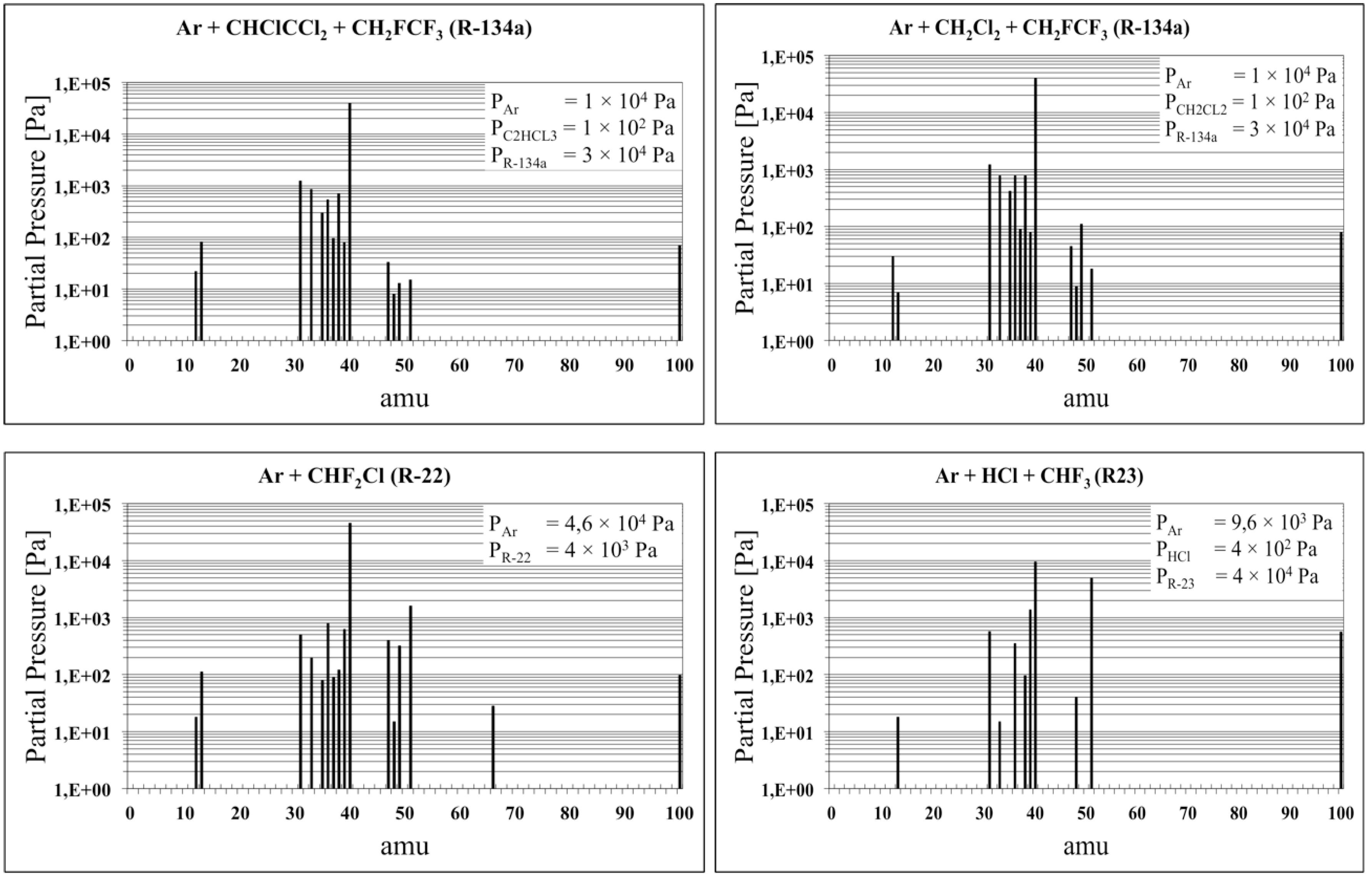
When these substances are brought to high temperatures (≥650 K), they tend to dissociate into more stable radicals. As
Figure 1 clearly highlights, starting with a mixture of Ar and 20% of these hydrocarbons, the molecular species present after one hour of permanence at 670 K are mostly hydrochloric acid (H
35Cl and H
37Cl), while the other molecules detected by the RGA are present in very low quantity, being all below 100 Pa.
These spectra, recorded every 30 s during the treatment, show that the dissociation of the Freon molecules is a rather slow process: a rapid heating of the gas to 670 K will not ensure that all the Freon gas is dissociated. From this dynamic measurement, rough estimates were made, which indicate that only 3% to 6% of the Freon dissociates during the first 5 min and this dissociation rate remains fairly constant.
The steady state condition can be reached only if dissociation and recombination rates are the same, and this is strictly true if the quantity of Freon is fixed and the treatment temperature is 670 K. In order to perform the CdTe treatment in a steady state condition, only time periods of at least 10 min were used. At higher temperatures the products of dissociation are different, often involving the double bond between two carbon atoms. When these compounds are formed, the reaction is no longer reversible, and all of the Freon present will then dissociate; for example, at a temperature of 800 K all the tested freons are completely dissociated after 5 min.
Figure 1 shows that the treatment is always carried out in presence of hydrochloric acid as the RGA measurement confirms. In these conditions, since the reactivity is very high, the system becomes critical and the results, summarized in
Table 2, show that the efficiencies of the cells produced are lower than 10%. This critical condition, due to excessive reactivity, is also highlighted by the standard deviation of the photovoltaic parameters, which is always more than three times the standard deviation normally obtained using the reference treatment with R-22.
Now we have to answer to the following question: what is the main difference between LCHYs and R-22 from the CdTe treatment point of view? Up to now, we considered only the CdTe-Cl2 interaction, but R-22 carries F2 and/or F-based species with a probable formation of a fluorine compound. Some of these are stable materials at the treatment temperature, but in presence of chlorine they could present a metastable phase. The formation of fluorine compounds, such as CdF2, is effective in lowering the formation rate of the chlorine containing counterparts (CdCl2), decreasing the chlorine aggressiveness and making the system easier to control. In order to align the LCHY treatment as much as possible to what is achieved using the R-22 system, chlorine-free fluorinated hydrocarbons were supplied into the treatment chamber. This solution provides an additional knob for controlling the process, i.e. adjusting the partial pressure of the FLHY to fine-tune the reactivity of the species containing chlorine. This method, being able to vary the amount of chlorine- and fluorine-containing species by independently managing the LCHY and FLHY partial pressures, proved to be even more effective than the R-22-based treatment.
Actually, the etching effect of the CdTe surface, typical of films treated with the LCHYs alone, decreases by increasing the quantity of fluorine in the treatment gas. As a consequence, the grain boundaries of the CdTe film are less carved and the chlorine action in the junction region is soft enough to passivate the structural defects, promoting the formation of an intermixing layer [
22] without destroying the interface between CdTe and CdS.
The FLHY species considered are the ones listed in
Table 3 and among them, those actually tested are: trifluoromethane R-23 (CHF
3), R-134a (1,1,1,2-tetrafluoroethane, CH
2FCF
3), and R-152a (1,1-difluoroethane, CH
3CHF
2). These fluorinated hydrocarbons are commonly used in refrigeration and are readily available. Furthermore, since hydrochloric acid is always present among the dissociation products of all the examined LCHYs, (see
Figure 1) the Ar + HCl + FLHY system was also tested.
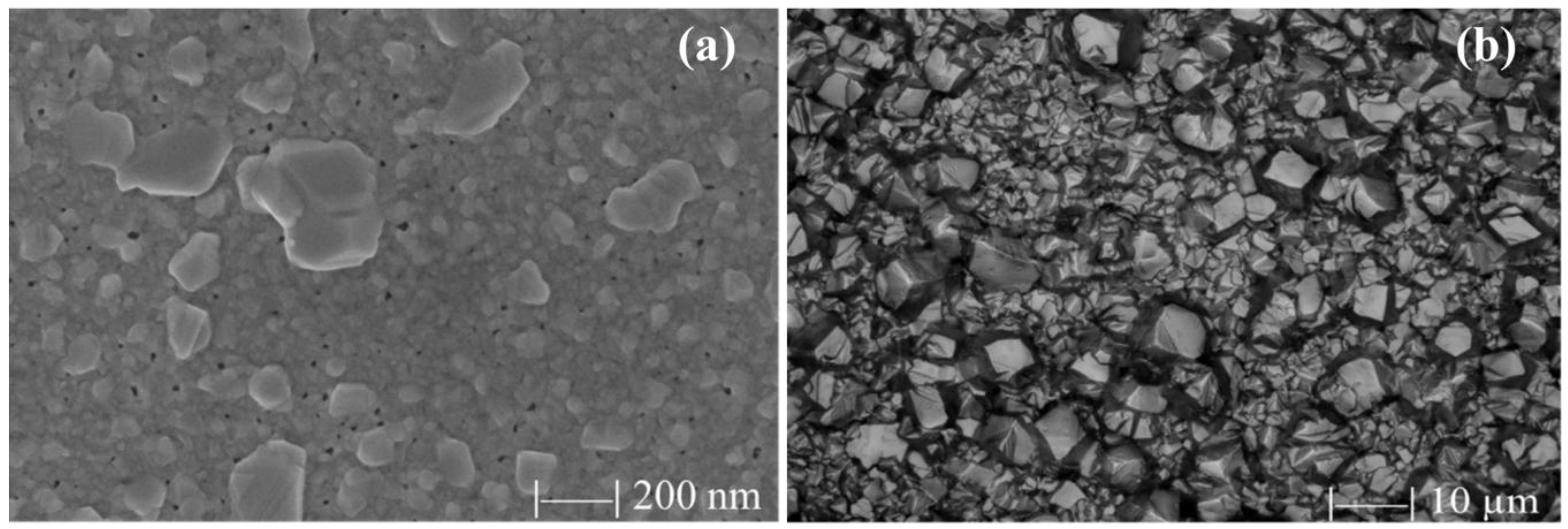
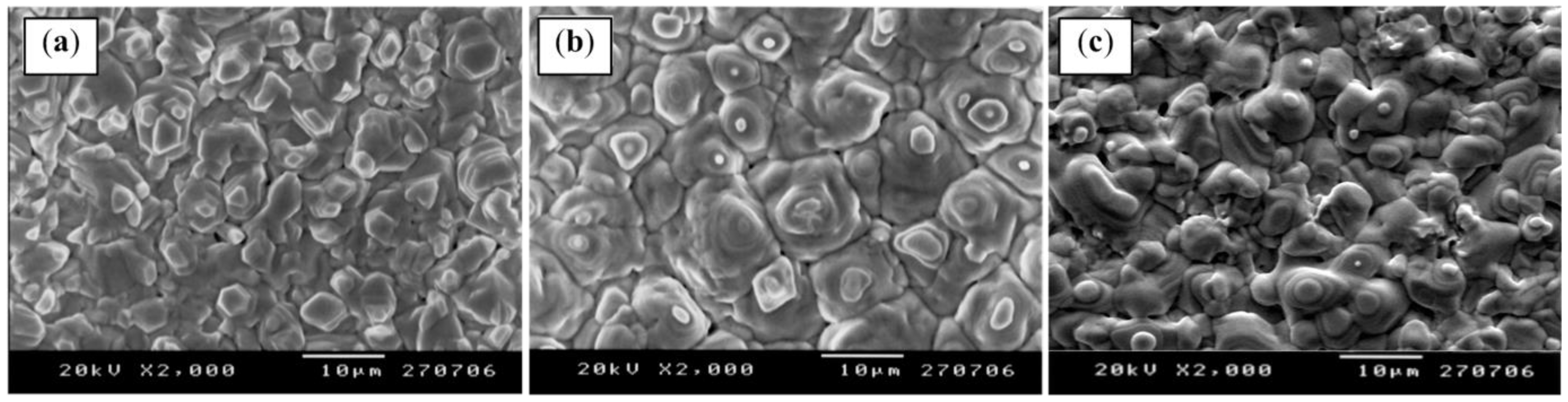
Figure 2 shows the morphology of a CSS-deposited CdTe film, 6 µm thick, as it appears,
Figure 2a, as deposited, and
Figure 2b,c after the Ar + R-22 and the Ar + HCl + R-23 processing, respectively. The treatment conditions are reported in
Figure 3.
The morphology of the surfaces shown in
Figure 2b,c presents the typical mesa-like structure resulting from the etching of the surface by chlorine and/or hydrogen chloride.
The crystalline grains tend to coalescence, becoming more compact with narrow boundaries.
Moreover, the formation of micro-particles of carbon on the surface of the CdTe, which occurs when using only the chlorinated compound, is inhibited, probably because the fluorine-containing gas tends to bond the carbon atoms. In
Figure 3, the RGA measurements concerning the CHClCCl
2 + R-134a + Ar, CH
2Cl
2 + R-134a + Ar, and the HCl + R-23 + Ar gas mixtures are compared to what is observed with the R-22 + Ar system.
These experiments conclusively show that the CdTe treatment, using liquid chlorinated hydrocarbons, can produce similar results to those achieved using the R-22 system if chlorine-free fluorinated hydrocarbons are added in the reaction chamber to control the chlorine reactivity.
The behavior of the solar cells built with CdTe films treated with the LCHY + FLHY gas mixture confirms the above observations. The treatment time for these samples was 15 min, whereas the trials referred to in
Figure 3 had treatment durations of one hour. The properties of the photovoltaic cells produced using these treatments are presented in
Table 4. The efficiency of these devices is quite high, showing that the diode parameters of the devices are very good. The low standard deviation of all the parameters suggests high reproducibility, which means the chlorine treatment, exploiting the LCHY and Ar gas mixture to which FLHY has been added, is completely under control. As the back contact is not contaminated by carbon filaments, which are present if the chlorinated hydrocarbon is used alone, a very good time stability of the solar cell is expected. In fact, CdTe solar cells, kept under one sun at 353 K (accelerated lifetime test) in a metal box, show a very stable behavior exhibiting, after 1300 h, an efficiency of more than 93% of the initial performance.
3.2. Pinholes and Grain Boundaries Passivation
Up to now, we always considered CdTe films with thickness greater than 6 µm, which corresponds to a standard for this CSS-deposited film (
Figure 4b). What happens if the thickness is reduced to a third of the standard (
Figure 4a)? The crystalline grains are reduced in size, highlighting widened grain boundaries with some voids, which favor the formation of shunt-paths and, therefore, of weak
p-n junctions. As a result, lower photovoltages and fill factors are obtained.
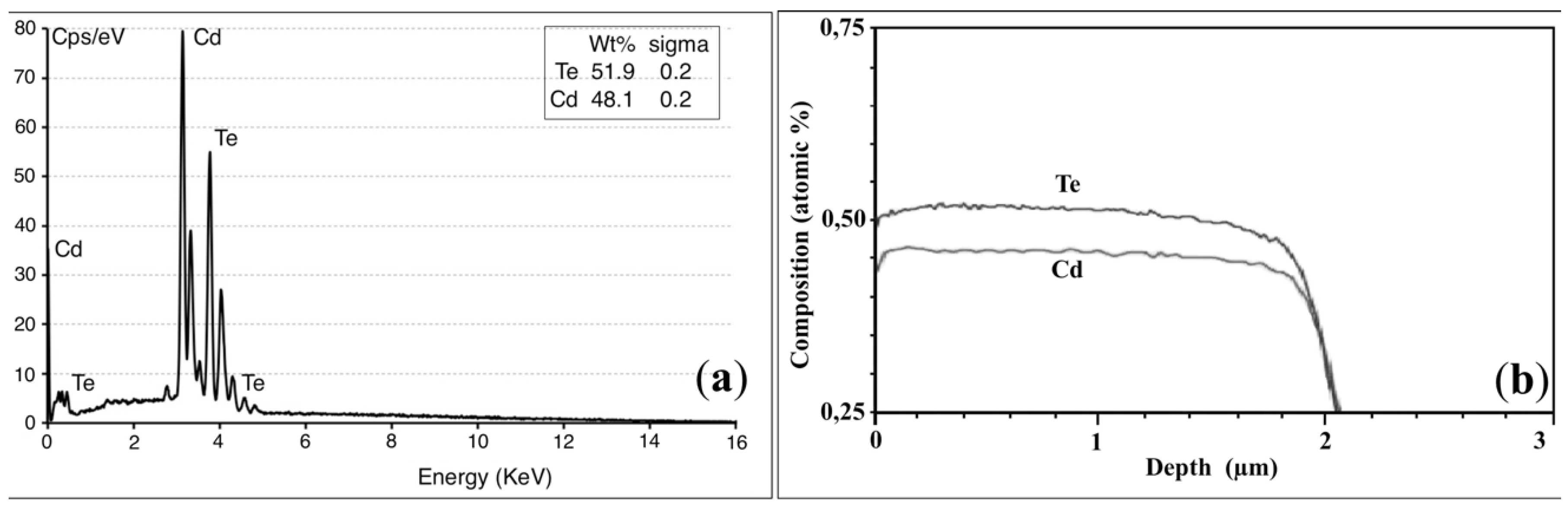
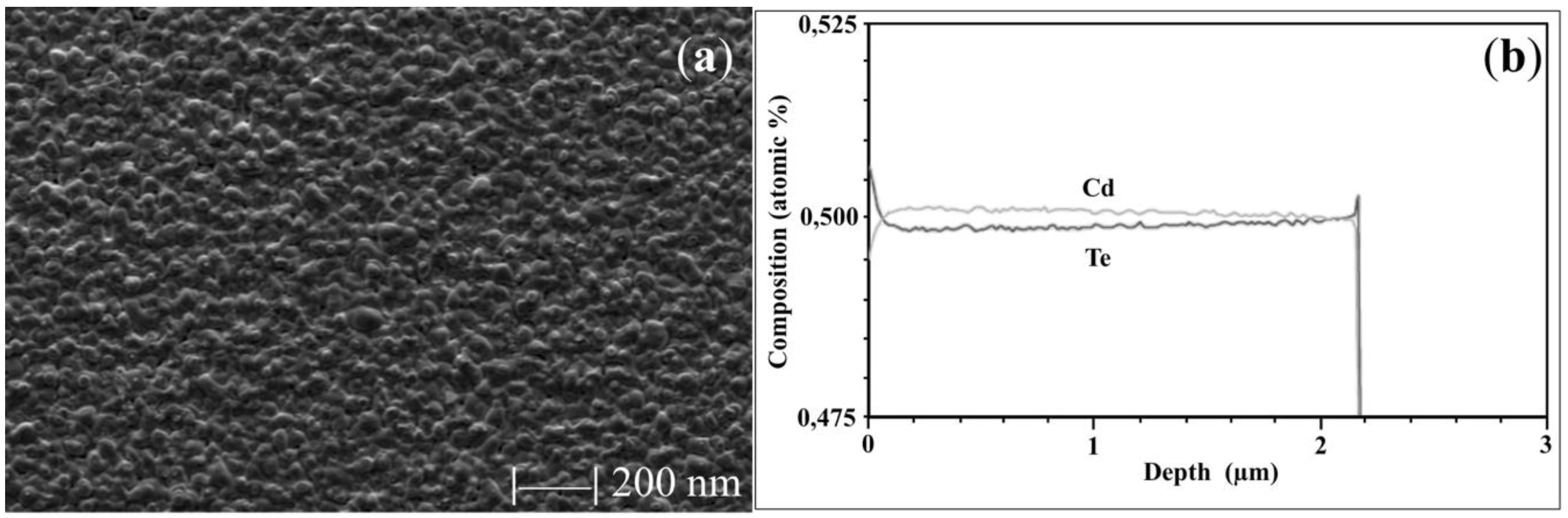
From a stoichiometry point of view, there is no difference between thicker or thinner films if CdTe is deposited by CSS; in both cases the CdTe layer exhibits a Te-rich surface as shown by SEM-EDX measurements performed on a CSS-deposited film (
Figure 5a). Making the chlorine treatment by using HCl, LCHY, and by adding FLHYs, offers a great advantage since the CdTe surface continues to be Te-rich after the treatment; the peculiarity is that this treatment does not introduce Cd into the CdTe film from outside leaving the Cd-vacancies un-compensated (
Figure 5b); this fact does not happen if a cadmium salt like CdCl
2 is used. During this study, we discovered this important feature, which could be exploited by making the back-contact directly on the surface of the CdTe layer. In fact, it is commonly accepted by the research community that, in order to obtain a good ohmic contact with
p-type CdTe, a Te-rich surface is needed.
On the contrary, sputtered CdTe films, being deposited at a lower temperature (<623 K) if compared with those deposited with the CSS technique (>770 K), are very compact with an excellent coverage already at very low thickness and completely hole-free (
Figure 6a). Moreover, CdTe films deposited by RF sputtering in a pure Ar atmosphere at a temperature around 570 K show a Cd-rich stoichiometry. Furthermore, these films exhibit a resistivity of about 1 × 10
3 Ωcm with a
n-type behavior, presumably due to the Te-vacancies as the Cd/Te ratio suggest (
Figure 6b), despite the starting material has a purity of 99.999% with a Cd/Te ratio R
Cd/Te = 1.
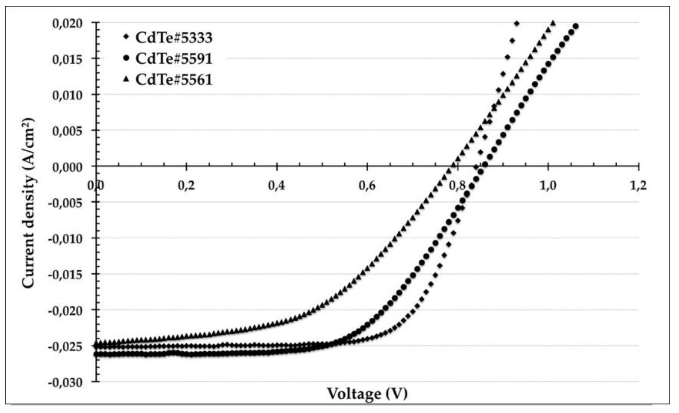
Since the decrease of the CdTe film thickness will become increasingly mandatory in the near future, we tried to fill in the holes of a 3 µm thick CSS-CdTe film with a 100–200 nm thick sputtered-CdTe film. This bi-layer was treated at a temperature of 670 K in HCl + FLHY + Ar gas mixture and then the resulting solar cell was completed by depositing the standard back-contact.
The obtained solar cell exhibits open circuit voltage Voc ≈ 830 mV, short circuit current density Jsc ≈ 25–26 mA/cm
2, fill factor FF ≈ 0.70 and efficiencies Eff ≈ 15% as it is shown in
Figure 7 and summarized in
Table 5. In order to explain this results an ad hoc hypothesis was made: at the back-contact side, of a CSS as-deposited polycrystalline CdTe film, the grain boundaries (GBs) act as electron traps, while rejecting holes. After the chlorine treatment the GBs have sufficiently strong, localized Cl segregation (n-type levels) to cause the formation of a p-n-p junction across the GB. The built-in field, formed in the regions between the GB and grain interior, will act as a mirror for the minority carrier and will help separate photo-generated carriers reducing the carrier recombination rate.
This effect is well explained by Li
et al. in [
34]. Moreover, we increase this multiple effect by using a very thin n-type CdTe layer, which is segregated into the GBs of the p-type CSS-deposited CdTe underneath layer after the chlorine treatment. The resulting
p-n junction, formed between the grain boundaries and the bulk, could reject the minority carriers inside the grain increasing their lifetime.
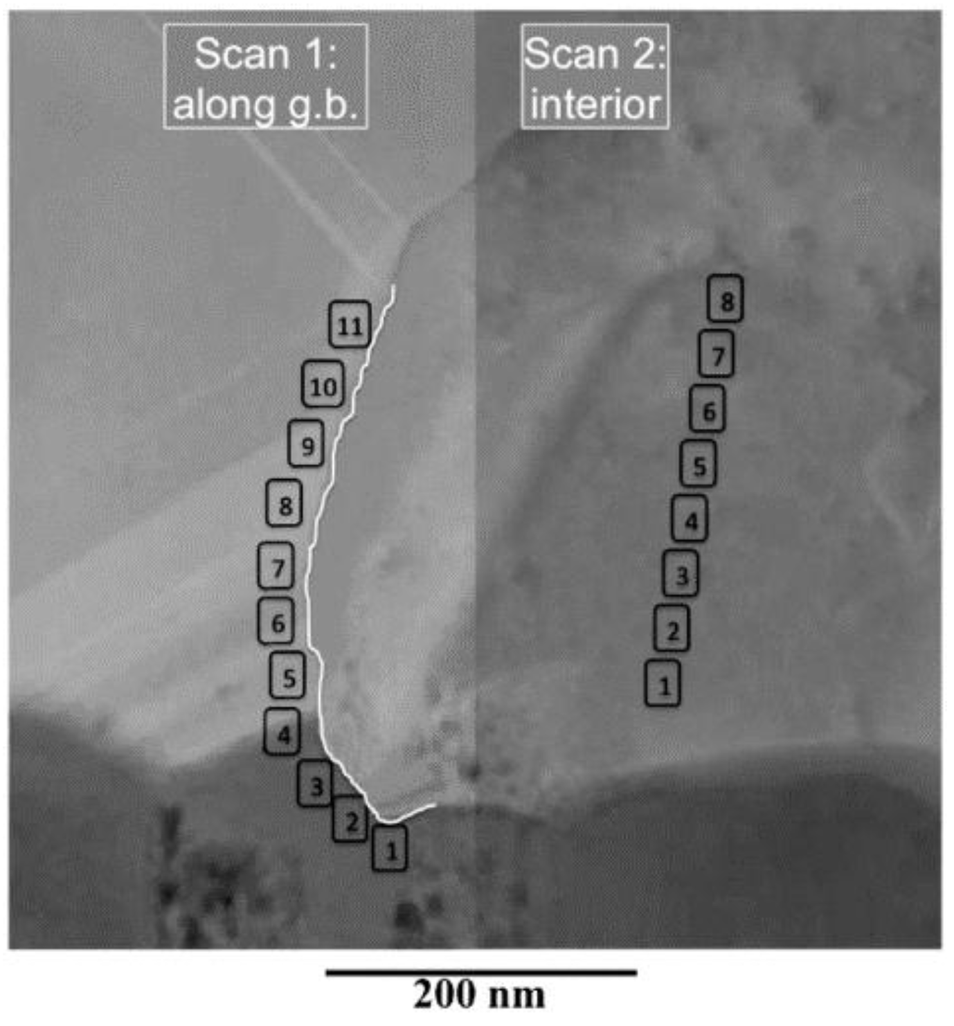
This active passivation of the grain boundaries is effective also against the formations of shunt paths, only if the the bottom of the hole does not completely leave uncovered the buffer layer (CdS) and this is true only when the thicknesses of the CSS-CdTe layer are ≥2 µm. This hypothesis is confirmed by the STEM-EDX analysis performed on a CdTe bilayer immediately after the chlorine-treatment as it is shown in
Figure 8 and in
Table 6.


