
Feasibility Study of a Scroll Expander for Recycling Low-Pressure Exhaust Gas Energy from a Vehicle Gasoline Engine System


Abstract
:1. Introduction
2. Mathematical Modelling of the Engine Exhaust Recycling System
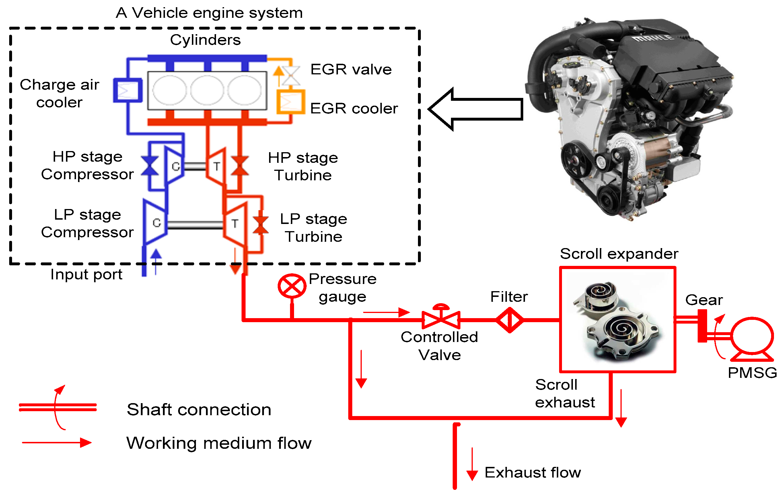
2.1. Description of the Proposed Engine Exhaust Recycling System
2.2. Mathematical Modelling of the Engine Exhaust Recycling System
2.3. Mathematical Modelling for Permanent Magnet Synchronous Generators
3. Results and Discussion
3.1. Recovering Exhaust Energy Using an Unmodified Scroll Expander
- (1)
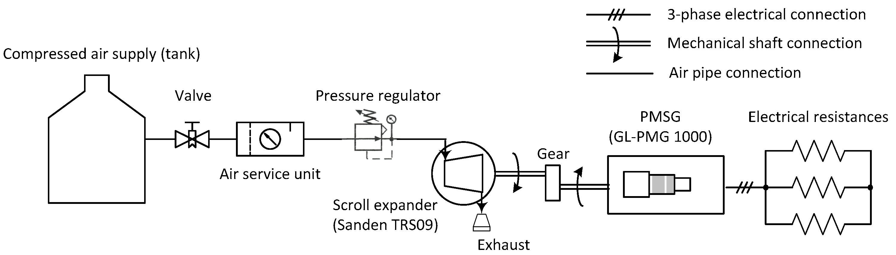
- After a post-combustion gas filter (or other similar function devices) operation, the exhaust gas from the engine system can flow into the scroll expander without any possible damage to the scroll mechanism (Figure 1)
- (2)
- The effect of gas leakage between scroll chambers is not taken into consideration;
- (3)
- In practice, after the exhaust energy recycling system connecting to the discharge port, the original engine system working conditions may be affected because the down-stream gas pressure of the scroll expander could possibly propagate back to the up-stream. In our analysis, this is not considered at the moment. The engine system exhaust is treated as a “stable gas supply with low pressure (1.30 × 10⁵ Pa) and high temperature (947.50 K)” to the scroll expander.
- (4)
- It is assumed that the sufficient combustion process happens in the gasoline engine cylinders and all the reactants convert to the products via the combustion. Then the corresponding chemical reaction can be described as ([30,31]): 2C8H18 + 25O2 → 16CO2 + 18H2O. Therefore, the properties of the post-combustion mixture will be considered and used in the relevant simulation study.
3.2. Evaluation on Recovering Exhaust Energy with Structure Modified Scrolls
3.2.1. Case I—Increasing the Scroll Expander Intake Port
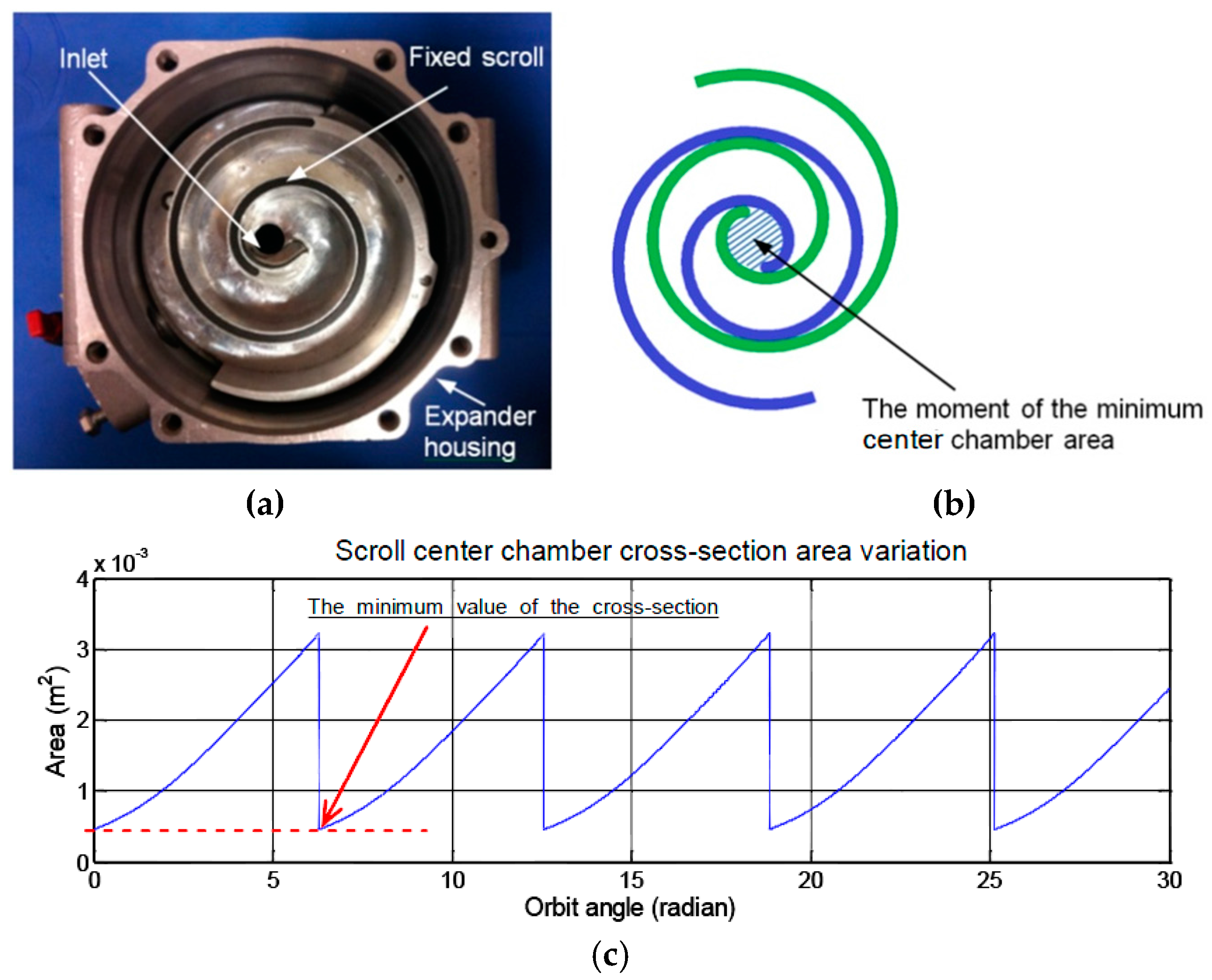
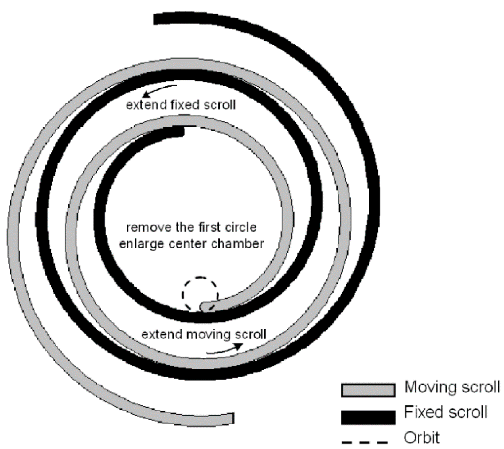
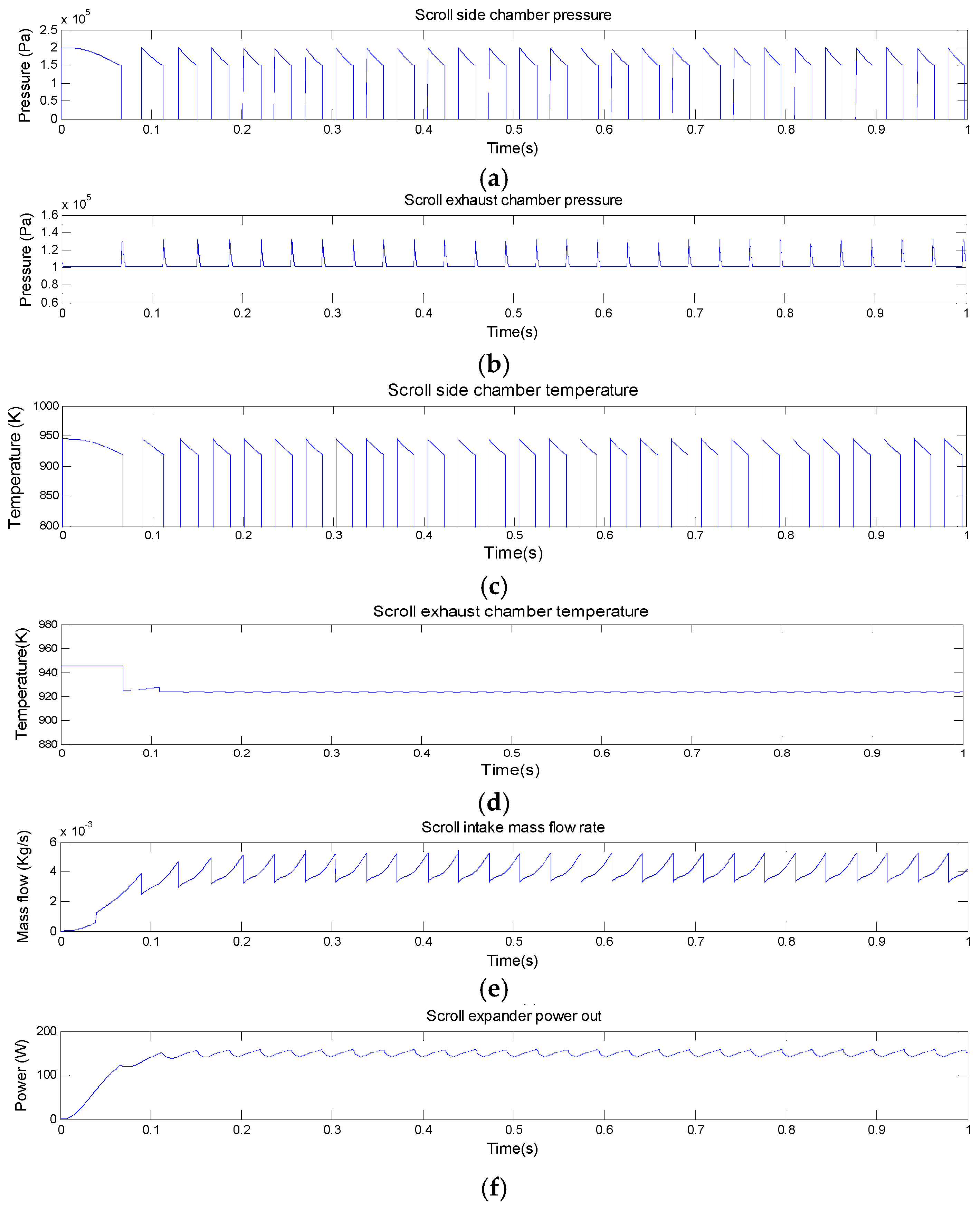
3.2.2. Case II—Enlarging Volume of the Scroll Expander Center Chamber
- (1)
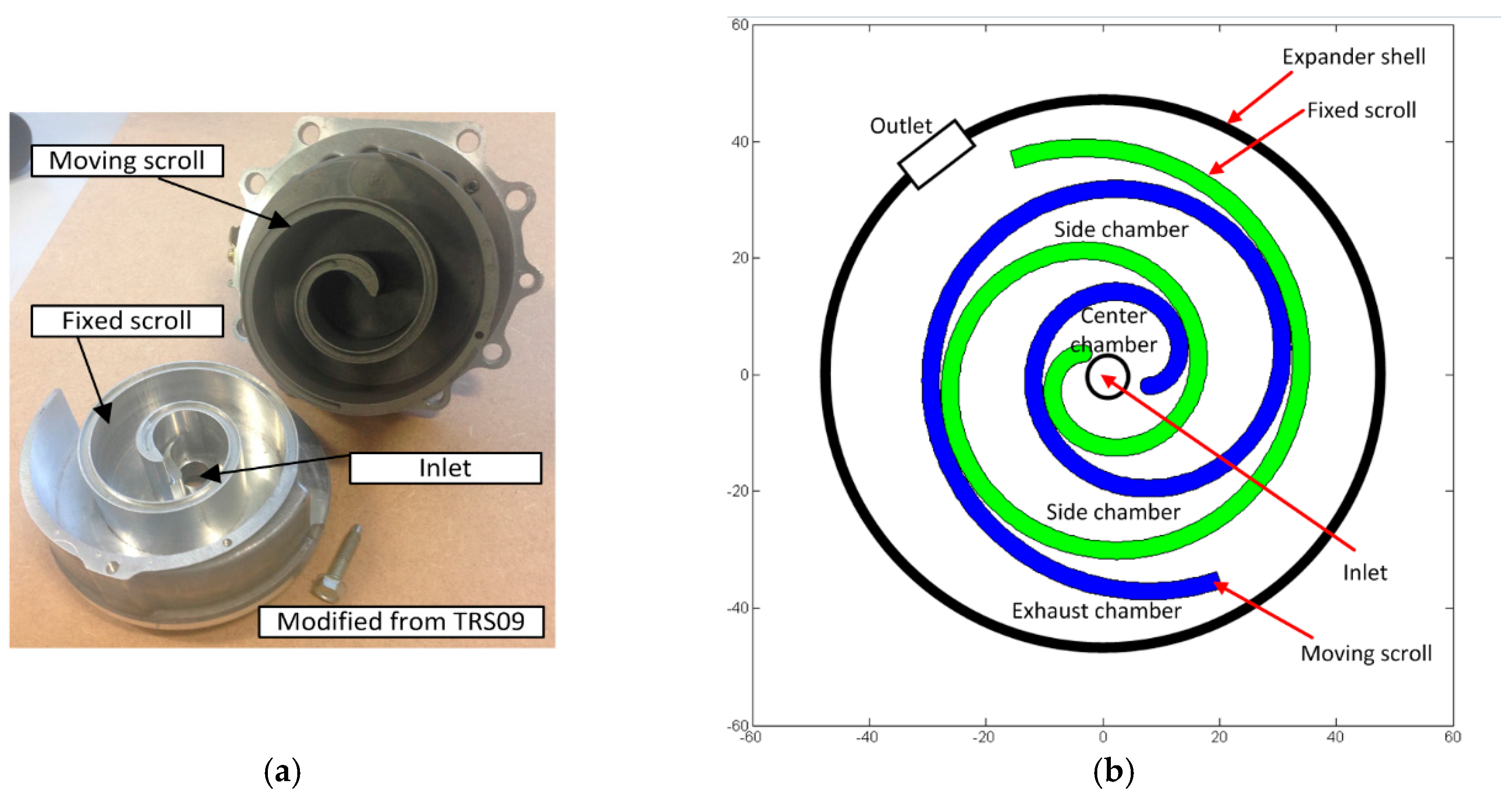
- the first circle wrap of the original fixed and moving scrolls is removed to increase the volume of the center chamber of the scroll expander (Figure 8);
- (2)
- increasing the inlet port size further to get more exhaust gas flow into the engine exhaust recycling system (in this case, the open area of the intake port is twelve times the original intake and the reason for this is that the minimum value of the newly formed center chamber cross-section area needs to be considered, which is similar to the descriptions in the first paragraph of Section 3.2.1.)
- (3)
- extending one new circle scroll wrap from both the fixed and moving scroll ending points in order to maintain the original number of scroll wraps for these two scrolls.
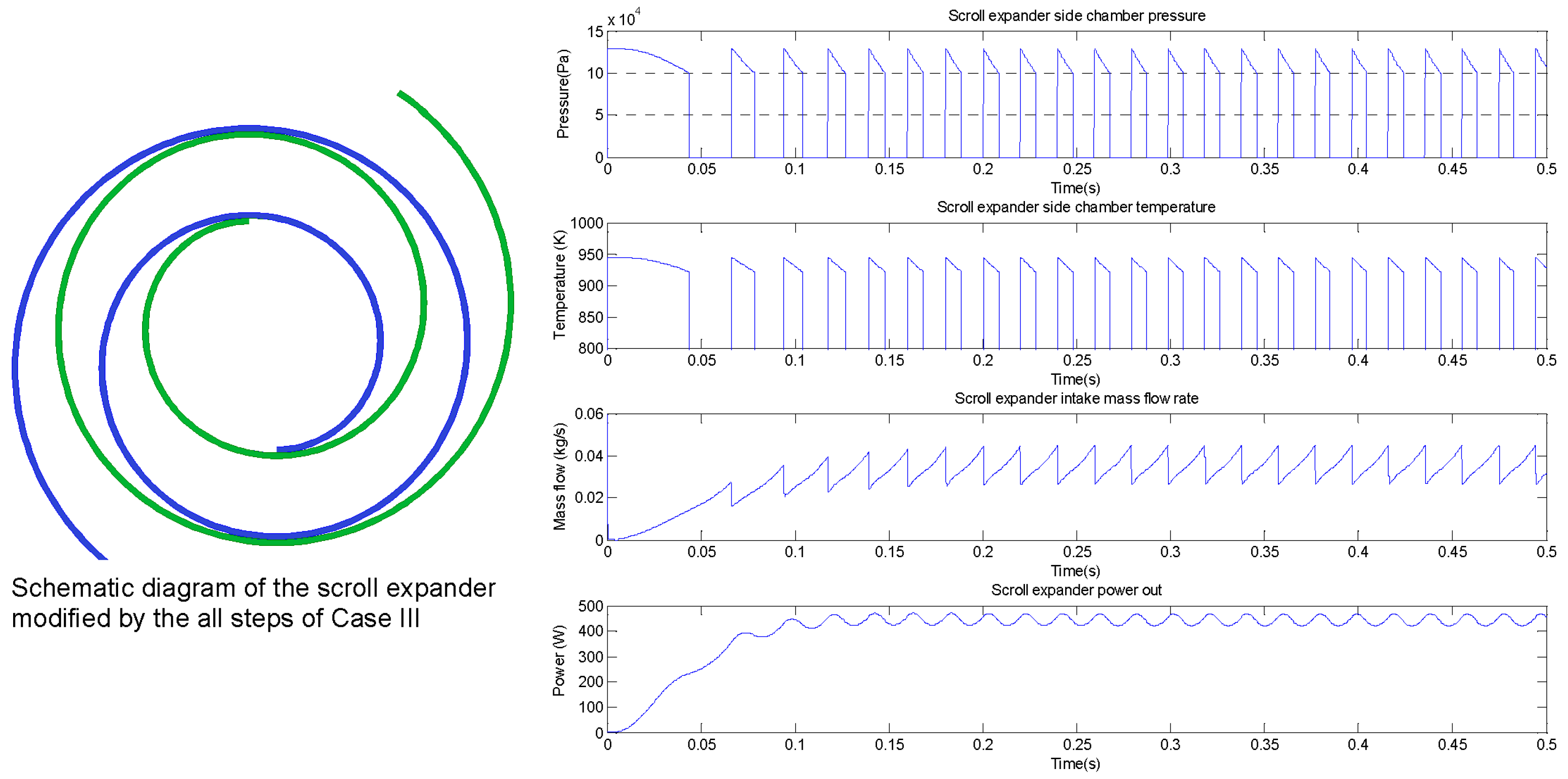
3.2.3. Case III—Modifying Scroll Geometry Parameters
- (1)
- keeping the modifications of the scroll expander from the steps of Case II;
- (2)
- increasing the parameter of the moving scroll orbit radius to three times the original value of this parameter;
- (3)
- according to the nature of the scroll geometry, the slope of the curvature radius (k) to the moving and the fixed scrolls need to be recalculated, i.e., k = (αs + δs)/π, where δs is the thickness of the two scrolls (refer to [25]);
- (4)
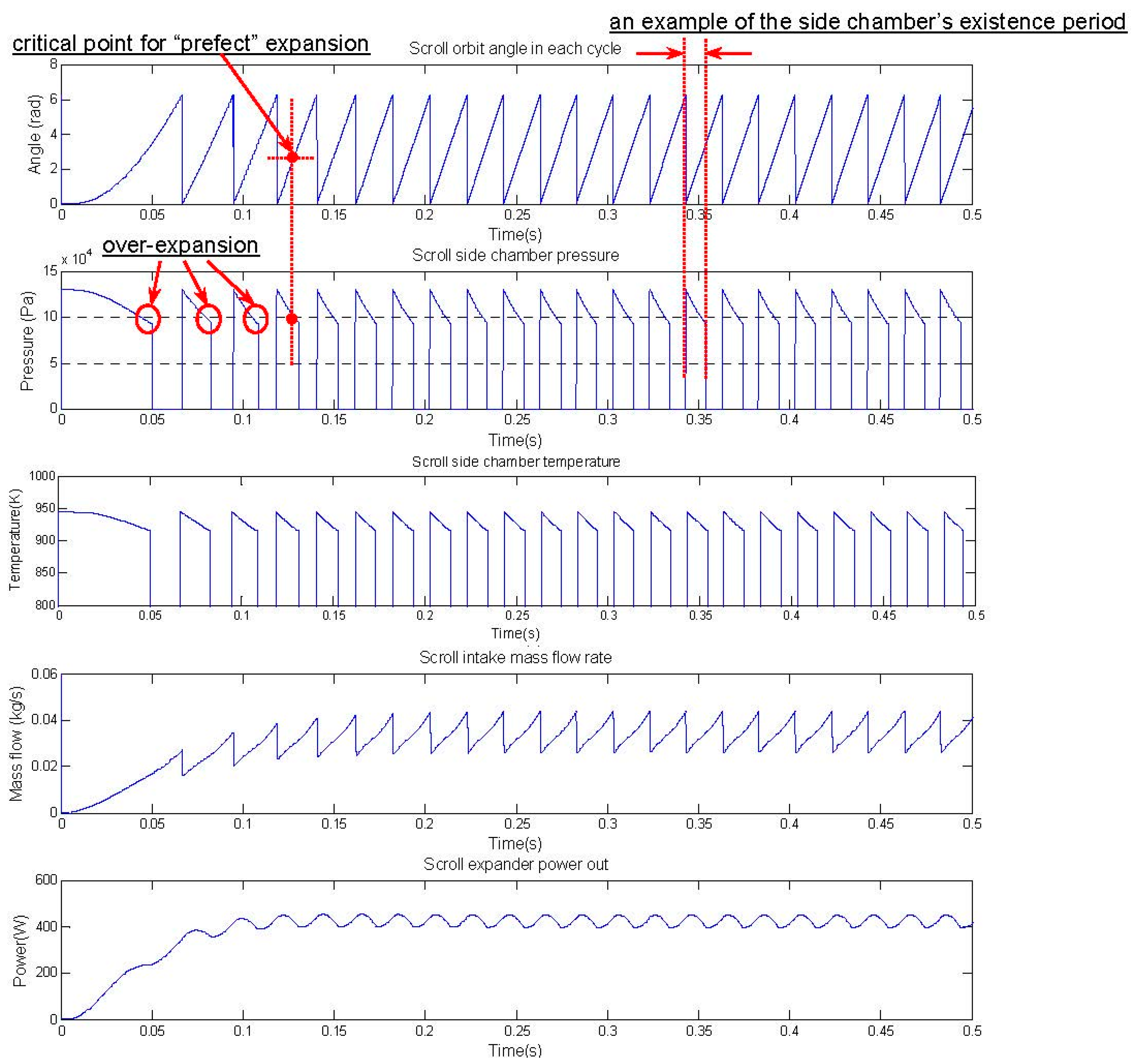
- adjusting the lengths of the two scroll wraps via the simulation study, to avoid the over-expansion problem.
4. Conclusions
Acknowledgments
Author Contributions
Conflicts of Interest
Nomenclature
| Effective open area of the orifice (m2) | |
| Discharge coefficient | |
| Specific heat of air at pressure T () | |
| Specific enthalpy of air (J/kg) | |
| Specific enthalpy of the air on a molar basis (J/mol) | |
| Specific enthalpy of species from the inlet of scroll expander (J/kg) | |
| Specific enthalpy of species to the outlet of scroll expander (J/kg) | |
| Current in the different axes for the PMSG modelling (Ampere) | |
| The whole energy recycling system’s moment of inertia (kg·m2) | |
| Slope of the curvature radius | |
| Coefficient of the scroll expander viscous friction | |
| Coefficient of the PMSG viscous friction | |
| Coefficient of the gear viscous friction | |
| Combined effect on torque from the scroll expander static and Coulomb frictions | |
| Combined effect on torque from the static and Coulomb frictions of the PMSG and gear | |
| , | Inductances of d axis and q axis respectively (H) |
| Molar mass of air, g/mol | |
| Average molar mass of the post-combustion mixture (g/mol) | |
| Mass of the air (kg) | |
| Mass flow rate of the air (kg/s) | |
| Mass flow rate for species from the inlet of scroll expander (kg/s) | |
| Mass flow rate for species to the outlet of scroll expander (kg/s) | |
| Numbers of scroll wraps | |
| Number of the pole pairs in the PMSG | |
| Air pressure (Pa) | |
| The post-combustion mixture pressure inside the scroll expander chamber (Pa) | |
| Downstream pressure of the orifice (Pa) | |
| Upstream pressure of the orifice (Pa) | |
| Pressure difference between the adjacent chambers of the scroll expander (Pa) | |
| Radius of the orbit relevant to the moving scroll motion (m) | |
| Ideal gas constant (J·K−1·kg−1) | |
| Resistance of the PMSG stator windings (ohm) | |
| Combination effect description on torque from the scroll static and Coulomb frictions | |
| Air temperature (K) | |
| The scroll expander chamber temperature when the mixture filled in (K) | |
| Park transformation matrix | |
| Voltage in the different axes for the PMSG modelling (Volt) | |
| , | Line voltages of a-to-b phases and b-to-c phases respectively (Volt) |
| Volume (m3) | |
| The scroll expander chamber volume when the mixture filled in (m3) | |
| Total control volume of a scroll expander (m3) | |
| Molar volumetric concentration of the air (mol/m3) | |
| The initial point of the moving scroll curve (m) | |
| Height of the two scrolls’ wall (m) | |
| Orbit angle of the moving scroll (radian) | |
| Thickness of the moving and fixed scrolls (m) | |
| Ratio of specific heats | |
| Initial radius of the curvature for the moving scroll curve (m) | |
| Magnetic flux of the PMSG (Wb) | |
| Gear transmission ratio | |
| Scroll expander rotor angular speed (rad/s) | |
| PMSG rotor angular speed (rad/s) | |
| Angular position of the rotor of PMSG (radian) | |
| Scroll expander effective driving torque (Nm) | |
| Electromagnetic torque of the PMSG (Nm) |
Subscripts
| The axes for the PMSG modelling | |
| chamber | The scroll expander chamber |
| The axes for the PMSG modelling | |
| Species i containing in the post-combustion mixture from the engine combustion process | |
| The inlet and outlet of scroll expander | |
| The scroll expander’s center, side and exhaust chambers respectively |
Abbreviations
| AC | Alternating current |
| CAB | Compressed air battery |
| C8H18 | Octane |
| CO2 | Carbon dioxide |
| DC | Direct current |
| EGR | Exhaust gas recirculation |
| HCCI | Homogeneous charge compression ignition |
| HP | High pressure |
| H2O | Water |
| LP | Low pressure |
| Micro CHP | Micro combined hear & power system |
| NOX | Nitrogen oxides |
| O2 | Oxygen |
| PMSG | Permanent magnet synchronous generator |
| SI | Spark-ignition |
| UPS | Uninterrupted power supply |
References
- UK Department for Transport. Vehicle Licensing Statistics: Quarter 4 (October–December). Available online: https://www.gov.uk/government/statistics/vehicle-licensing-statistics-2014 (accessed on 16 October 2015).
- Chinese Ministry of Public Security. The Rapid Increase of Motor Vehicles and Drivers in 2014. Available online: http://www.mps.gov.cn/n16/n1252/n1837/n2557/4330449.html (accessed on 16 October 2015).
- Hedges & Company. United States Vehicle Ownership Data, Automobile Statistics and Trends. Available online: http://hedgescompany.com/automotive-market-research-statistics/auto-mailing-lists-and-marketing (accessed on 18 October 2015).
- US Department of Energy. Where the Energy Goes: Gasoline Vehicles, The Official U.S. Government Source for Fuel Economy 25 Information. Available online: https://www.fueleconomy.gov/feg/atv.shtml (accessed on 20 October 2015).
- Baglione, M.; Duty, M.; Pannone, G. Vehicle system energy analysis methodology and tool for determining vehicle subsystem energy supply and demand. In Proceedings of the 2007 SAE World Congress, Detroit, MI, USA, 16–19 April 2007.
- EU CO2 Emission Standards for Passenger Cars and Light-Commercial Vehicles. Available online: http://www.theicct.org/sites/default/files/publications/ICCTupdate_EU-95gram_jan2014.pdf (accessed on 20 October 2015).
- Jia, N.; Wang, J.; Nuttall, K.; Wei, J.; Xu, H.; Wyszynski, M.L.; Qiao, J.; Richardson, M.J. HCCI engine modeling for real-time implementation and control development. IEEE/ASME Trans. Mechatron. 2007, 12, 581–589. [Google Scholar] [CrossRef]
- Khodabakhshian, M.; Feng, L.; Wikander, J. Predictive control of the engine cooling system for fuel efficiency improvement. In Proceedings of the IEEE International Conference on Automation Science and Engineering (CASE), Taipei, Taiwan, 18–22 August 2014; pp. 61–66.
- Romagnoli, A.; Wan-Salim, W.S.-I.; Gurunathan, B.A.; Martinez-Botas, R.F. Assessment of supercharging boosting component for heavily downsized gasoline engines. In Proceedings of the 11th International Conference on Turbochargers and Turbocharging, London, UK, 13–14 May 2014.
- Lampton, C. How Exhaust Heat Recovery and Recirculation Works. How Stuffworks Website. Available online: http://auto.howstuffworks.com/fuel-efficiency/hybrid-technology/exhaust-heat-recovery-recirculation.htm (accessed on 20 October 2015).
- Bari, S.; Hossain, S.N. Design and optimization of compact heat exchangers to be retrofitted into a vehicle for heat recovery from a diesel engine. Procedia Eng. 2015, 105, 472–479. [Google Scholar] [CrossRef]
- Hossain, S.N.; Bari, S. Waste heat recovery from exhaust of a diesel generator set using organic fluids. Procedia Eng. 2014, 90, 425–430. [Google Scholar] [CrossRef]
- Bari, S.; Rubaiyat, S. Additional power generation from the exhaust gas of a diesel engine using ammonia as the working fluid. In Proceedings of the SAE 2014 World Congress & Exhibition, Detroit, MI, USA, 8–10 April 2014.
- Vance, J.B.; Singh, A.; Kaul, B.C.; Jagannathan, S.; Drallmeier, J.A. Neural network controller development and implementation for spark ignition engines with high EGR levels. IEEE Trans. Neural Netw. 2007, 18, 1083–1100. [Google Scholar] [CrossRef] [PubMed]
- Park, Y.; Bae, C. Experimental study on the effects of high/low pressure EGR proportion in a passenger car diesel engine. Appl. Energy 2014, 133, 308–316. [Google Scholar] [CrossRef]
- Ibrahim, A.; Bari, S. Effect of varying compression ratio on a natural gas SI engine performance in the presence of EGR. Energy Fuels 2009, 23, 4949–4956. [Google Scholar] [CrossRef]
- Ibrahim, A.; Bari, S.; Bruno, F. A study on EGR utilization in natural gas SI engines using a two-zone combustion model. SAE Tech. Paper 2007. [Google Scholar] [CrossRef]
- Yanagisawa, T.; Fukuta, Y.; Ogi, T.; Hikichi, T. Performance of an oil-free scroll-type air expander. In Proceedings of the ImechE Conference Trans on Compressors and Their Systems, Hamamatsu, Japan, 9–12 September 2001; pp. 167–174.
- Luo, X.; Sun, H.; Wang, J. An energy efficient pneumatic-electrical system and control strategy development. In Proceedings of the American Control Conference, San Francisco, CA, USA, 29 June–1 July 2011; pp. 4743–4748.
- Wang, J.; Luo, X.; Yang, L.; Shpanin, L.M.; Jia, N.; Mangan, S.; Derby, J.W. Mathematical Modeling Study of Scroll Air Motors and Energy Efficiency Analysis—Part II. IEEE/ASME Trans. Mechatron. 2011, 16, 122–132. [Google Scholar] [CrossRef]
- Flow Battery Ltd. Website. Case Study of Compressed Air Batteries (CAB) Application. Available online: http://www.flowbattery.co.uk/case-studies/national-grid-case-study (accessed on 21 October 2015).
- Gao, X.; Li, L.S.; Zhao, Y.; Shu, P.C.; Shen, J. Research on a scroll expander used for recovering work in a fuel cell. Int. J. Thermodyn. 2004, 7, 1–8. [Google Scholar]
- Luo, X.; Wang, J.; Sun, H.; Derby, J.W.; Mangan, S.J. Study of a New Strategy for Pneumatic Actuator System Energy Efficiency Improvement via the Scroll Expander Technology. IEEE/ASME Trans. Mechatron. 2013, 18, 1508–1518. [Google Scholar] [CrossRef]
- Dieckmann, J. Waste heat waste heat-to-power using scroll expander for Organic Rankine Bottoming Cycle. U.S. DOE Advanced Manufacturing Office Peer Review Meeting Presentation. Available online: http://energy.gov/sites/prod/files/2014/06/f16/14-TIAX_AMO_RD_Project_Peer_Review_2014.pdf (accessed on 21 October 2015).
- Wang, J.; Yang, L.; Luo, X.; Mangan, S.; Derby, J.W. Mathematical Modeling Study of Scroll Air Motors and Energy Efficiency Analysis—Part I. IEEE/ASME Trans. Mechatron. 2011, 16, 112–121. [Google Scholar] [CrossRef]
- Sun, H.; Luo, X.; Wang, J. Feasibility study of a hybrid wind turbine system—Integration with compressed air energy storage. Appl. Energy 2015, 137, 617–628. [Google Scholar] [CrossRef]
- Luo, X.; Sun, H.; Wang, J. A Novel Magnetic Scroll Expander as a Drive for Electricity Generation. In Proceedings of the 7th IET International Conference on Power Electronics, Machines and Drives, Manchester, UK, 8–10 April 2014; pp. 1–6.
- Fitzgerald, A.E.; Kingsley, C.; Stephen, D.U. Electric Machinery, 5th ed.; McGraw-Hill Inc.: Singapore, 1992; pp. 254–272. [Google Scholar]
- Grenier, D.; Dessaint, L.A.; Akhrif, O.; Bonnassieux, Y.; Le Pioufle, B. Experimental nonlinear torque control of a permanent-magnet synchronous motor using saliency. IEEE Trans. Ind. Electron. 1997, 44, 680–687. [Google Scholar] [CrossRef]
- Heywood, J. Internal Combustion Engine Fundamentals; McGraw-Hill, Inc.: New York, NY, USA, 1988; pp. 371–470. [Google Scholar]
- Ceviz, M.A.; Kaymaz, İ. Temperature and air–fuel ratio dependent specific heat ratio functions for lean burned and unburned mixture. Energy Convers. Manag. 2005, 46, 2387–2404. [Google Scholar] [CrossRef]
- Quoilin, S.; Declaye, S.; Legros, A.; Guillaume, L.; Lemort, V. Working fluid selection and operating maps for Organic Rankine Cycle expansion machines. In Proceedings of the 21st International Compressor Conference, West Lafayette, IN, USA, 14–19 July 2012; Volume 1546, pp. 1–10.
- Wei, J.L.; Wang, J.; Wu, Q.H. Development of a Multisegment Coal Mill Model Using an Evolutionary Computation Technique. IEEE Trans. Energy Convers. 2007, 22, 718–727. [Google Scholar] [CrossRef]


| Group No. | Working Condition Settings | Steady-state Test Results of the Scroll Expander |
|---|---|---|
| 1st test | supply pressure 3.75 × 10⁵ Pa, supply temperature 293 K | mass flow rate 7.65 × 10⁻³ kg/s, power output 385.1 W, outlet temperature 262 K |
| 2nd test | supply pressure 3.50 × 10⁵ Pa, supply temperature 293 K | mass flow rate 6.68 × 10⁻³ kg/s, power output 327.3 W, outlet temperature 265 K |
| 3rd test | supply pressure 3.00 × 10⁵ Pa, supply temperature 293 K | mass flow rate 4.74 × 10⁻³ kg/s, power output 221.3 W, outlet temperature 271 K |
| 4th test | supply pressure 2.50 × 10⁵ Pa, supply temperature 293 K | mass flow rate 3.15 × 10⁻³ kg/s, power output 125.9 W, outlet temperature 280 K |
| Parameters | Values of Parameters | Unit |
|---|---|---|
| Molecular mass of air | 28.97 | g/mol |
| Slope of radius of scroll curvature | 0.003183 | - |
| Orbit of the original moving scroll | 5.8 | mm |
| Thicknesses of the moving and fixed scrolls | 4.5 | mm |
| Heights of the moving and fixed scrolls | 33.3 | mm |
| Effective inlet area | 1.493 × 10⁻⁴ | m2 |
| Effective outlet area | 4.531 × 10⁻⁴ | m2 |
| Total controlled volume of the scroll expander | 4.1 × 10⁻³ | m3 |
| Ideal gas constant | 8.314 | J/(mol·K) |
| Molar mass of air | 28.97 | g/mol |
| Resistance of the stator windings | 6 | ohm |
| Inductance on the d axis | 17.5 | mH |
| Inductance on the q axis | 17.5 | mH |
| Magnetic flux induced by magnets | 0.44 | Wb |
| Gear transmission ratio | 7.5 | - |
| Static friction of the scroll expander | 0.318 | Nm |
| Static friction of the gear | 0.213 | Nm |
| Inertia of the whole energy recycling system | 0.002 | kgm2 |
| Group No. | Working Conditions | Parameter Settings |
|---|---|---|
| 1st | supply pressure 2.0 × 10⁵ Pa supply temperature 947.50 K | the original open area of scroll expander inlet |
| 2nd | supply pressure 1.5 × 10⁵ Pa supply temperature 947.50 K | the original open area of scroll expander inlet |
| 3rd | supply pressure 1.3 × 10⁵ Pa supply temperature 947.50 K | the original open area of scroll expander inlet |
| 4th | supply pressure 2.0 × 10⁵ Pa supply temperature 947.50 K | three times of the open area of original scroll inlet |
| 5th | supply pressure 1.5 × 10⁵ Pa supply temperature 947.50 K | three times of the open area of original scroll inlet |
| 6th | supply pressure 1.3 × 10⁵ Pa supply temperature 947.50 K | three times of the open area of original scroll inlet |
| Group No. | Working Conditions | Parameter Settings |
|---|---|---|
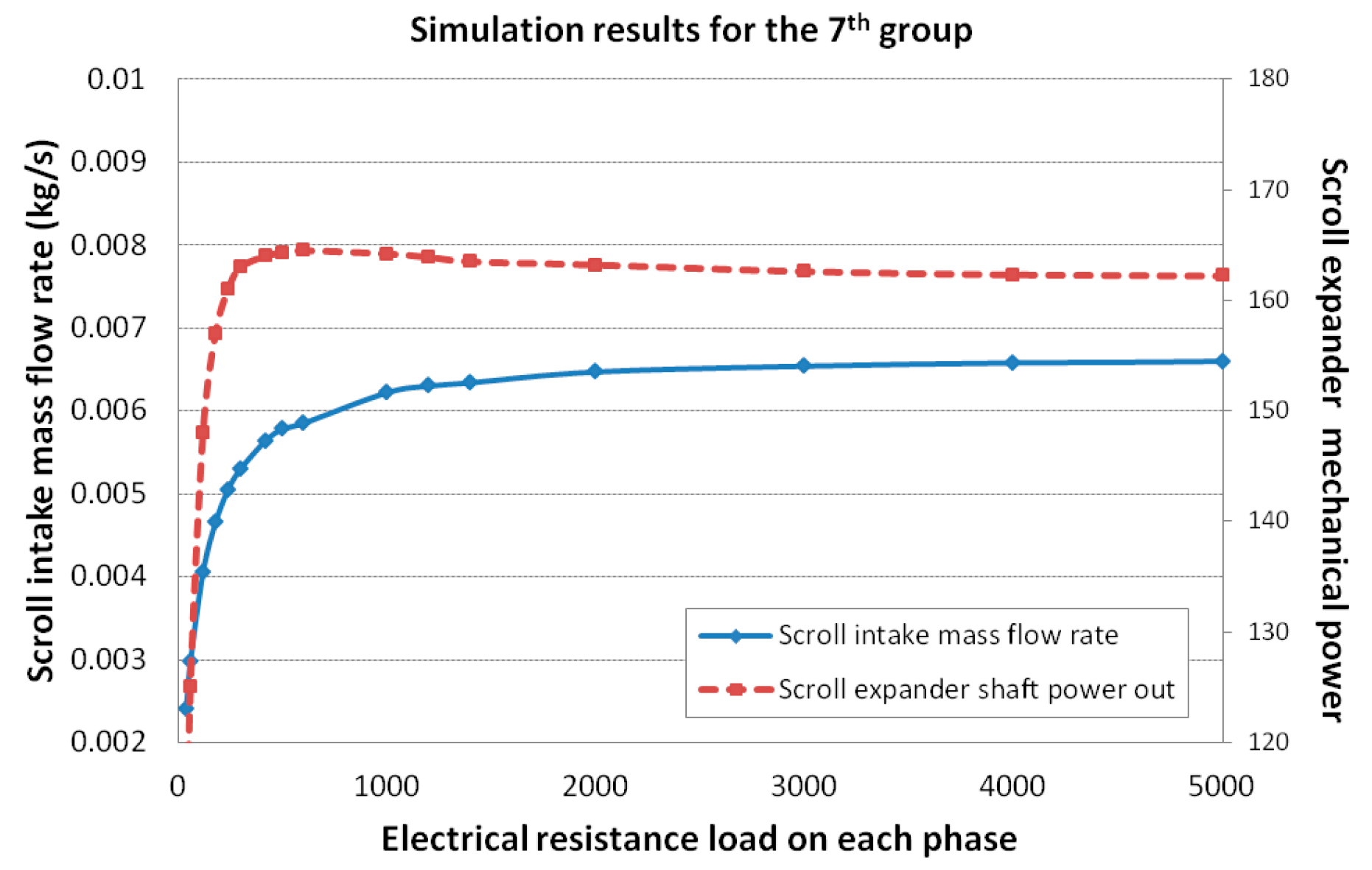
| 7th | supply pressure 2.0 × 10⁵ Pa supply temperature 947.50 K | The expander modified by the above steps, twelve times of the open area of original inlet |
| 8th | supply pressure 1.7 × 10⁵ Pa supply temperature 947.50 K | The expander modified by the above steps, twelve times of the open area of original inlet |
| 9th | supply pressure 1.5 × 10⁵ Pa supply temperature 947.50 K | The expander modified by the above steps, twelve times of the open area of original inlet |
| 10th | supply pressure 1.3 × 10⁵ Pa supply temperature 947.50 K | The expander modified by the above steps, twelve times of the open area of original inlet |
| Group No. | Working Conditions | Parameter Settings |
|---|---|---|
| 11th | supply pressure 2.0 × 10⁵ Pa supply temperature 947.50 K | the scroll expander modified by the steps described in Case III |
| 12th | supply pressure 1.7 × 10⁵ Pa supply temperature 947.50 K | the scroll expander modified by the steps described in Case III |
| 13th | supply pressure 1.5 × 10⁵ Pa supply temperature 947.50 K | the scroll expander modified by the steps described in Case III |
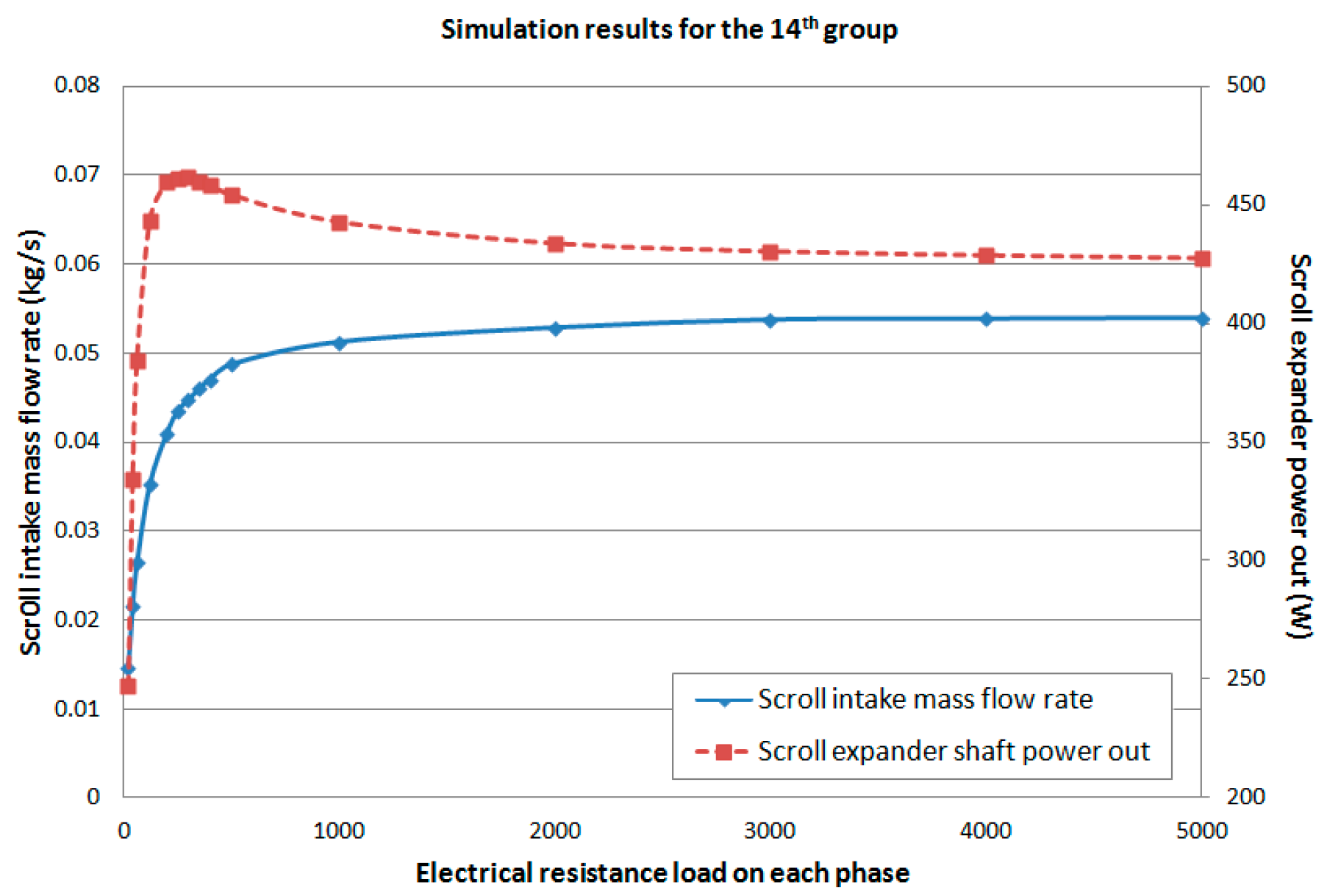
| 14th | supply pressure 1.3 × 10⁵ Pa supply temperature 947.50 K | the scroll expander modified by the steps described in Case III |
| Case No. | Brief Descriptions of Proposed Modifications | Summary of the Simulation Study |
|---|---|---|
| Case I | Three times the open area of the original inlet | With supply conditions at 2.0 × 10⁵ Pa and 947.50 K, 3.5% of the flow reference obtained (Figure 7), not suitable for the application. |
| Case II | Remove the first circle scroll wrap, expand the inlet port to twelve times of the open area of original inlet, and extend one new circle scroll wrap from the ending point | With supply conditions at 2.0 × 10⁵ Pa and 947.50 K, maximum 11.7% of the flow reference obtained (Figure 10), still not suitable for the application. |
| Steps 1 & 2 of Case III | Keep the modifications in Case II, extend the parameters of the moving scroll orbit radius and the slope of scroll curvature radius | With the exact required supply conditions (i.e., 1.3 × 10⁵ Pa and 947.50 K), >60% of the flow reference obtained (Figure 11); over- expansion exists (leading to back-flow) and thus it need further modification. |
| All steps of Case III | Aside from Steps 1 & 2 of Case III, take further action, i.e., adjustment of the lengths of the two scroll wraps via the simulation study to avoid overexpansion (Figure 12) | With the exact required supply conditions (i.e., 1.3 × 10⁵ and 947.50 K), maximum 93.9% of the flow reference obtained (Figure 13); no over-expansion issue; suitable for the exhaust gas recycling application. |
© 2016 by the authors; licensee MDPI, Basel, Switzerland. This article is an open access article distributed under the terms and conditions of the Creative Commons by Attribution (CC-BY) license (http://creativecommons.org/licenses/by/4.0/).
Share and Cite
Luo, X.; Wang, J.; Krupke, C.; Xu, H. Feasibility Study of a Scroll Expander for Recycling Low-Pressure Exhaust Gas Energy from a Vehicle Gasoline Engine System. Energies 2016, 9, 231. https://doi.org/10.3390/en9040231
Luo X, Wang J, Krupke C, Xu H. Feasibility Study of a Scroll Expander for Recycling Low-Pressure Exhaust Gas Energy from a Vehicle Gasoline Engine System. Energies. 2016; 9(4):231. https://doi.org/10.3390/en9040231
Chicago/Turabian StyleLuo, Xing, Jihong Wang, Christopher Krupke, and Hongming Xu. 2016. "Feasibility Study of a Scroll Expander for Recycling Low-Pressure Exhaust Gas Energy from a Vehicle Gasoline Engine System" Energies 9, no. 4: 231. https://doi.org/10.3390/en9040231