
A Study on Electric Vehicle Heat Pump Systems in Cold Climates

Institute of Refrigeration and Cryogenics, Shanghai Jiao Tong University, No. 800 Dongchuan Road, Shanghai 200240, China
*
Author to whom correspondence should be addressed.
Energies 2016, 9(11), 881; https://doi.org/10.3390/en9110881
Submission received: 19 August 2016
/
Revised: 1 October 2016
/
Accepted: 18 October 2016
/
Published: 27 October 2016
Abstract
:Electric vehicle heat pumps are drawing more and more attention due to their energy-saving and high efficiency designs. Some problems remain, however, in the usage of the heat pumps in electric vehicles, such as a drainage problem regarding the external heat exchangers while in heat pump mode, and the decrease in heating performance when operated in a cold climate. In this article, an R134a economized vapor injection (EVI) heat pump system was built and tested. The drainage problem common amongst external heat exchangers was solved by an optimized 5 mm diameter tube-and-fin heat exchanger, which can meet both the needs of a condenser and evaporator based on simulation and test results. The EVI system was also tested under several ambient temperatures. It was found that the EVI was a benefit to the system heating capacity. Under a −20 °C ambient temperature, an average improvement of 57.7% in heating capacity was achieved with EVI and the maximum capacity was 2097 W, with a coefficient of performance (COP) of 1.25. The influences of injection pressure and economizer capacity are also discussed in this article.
1. Introduction
With the rising concerns for environmental protection and energy economy, electric vehicles (EVs) seem to be a wise choice to meet both environmental demands and user needs, which has contributed to their increased worldwide use recently [1].
Unlike fuel vehicles, EVs do not have enough engine waste heat to meet heating demands in winter. A typical solution is to use a positive temperature coefficient (PTC) heater, but doing so causes a significant decrease in range due to low efficiency. According to [2], a 60% decrease in Urban Dynamometer Driving Schedule (UDDS) range may occur due to heating loads in winter.
The vehicle heat pump system is becoming a popular point of consideration due to a relatively high efficiency in meeting the heating requirements. Some studies have already been done in this area [3,4,5,6]. However, there are still some remaining problems to be solved.
One of them is the frosting of the external heat exchanger [7,8]. When the system is operated in heat pump mode, the external heat exchanger functions as an evaporator. Due to low ambient temperature and high relative humidity, the surface of the heat exchanger will frost. This may not be a problem in residential and commercial heat pump systems, as tube and fin heat exchangers (TFHXs) are used as the external heat exchangers. The water generated during defrosting can be easily drained. However, in current vehicle air conditioning systems, microchannel heat exchangers (MCHXs) with louvered fins are used as the external heat exchangers. The water generated from the defrosting process mostly accumulates between the fins, which is difficult to remove [9]. When the external heat exchanger frosts again, the remaining water will freeze and cause a dramatic performance decrease. Though lots of efforts have been made to optimize the drainage performance of MCHX [10], it is still a major barrier in vehicle heat pump systems [11]. One way to solve the drainage problem is to use TFHX as an external heat exchanger. Compared to MCHX, the TFHX has a relatively low heat exchange efficiency [12], and its performance needs to be optimized to meet the system requirements.
The second one is the significant decrease in heating performance of a heat pump system when operated in extremely cold regions. The low evaporating temperature leads to a low density of compressor suction, while the high pressure ratio of compression leads to a lower volume efficiency. The mass flow rate of the system becomes much lower and the discharge temperature becomes much higher than the normal condition.
Vapor injection (VI) makes it possible for heat pumps to operate in extremely cold conditions. Typically, there are two kinds of VI system structures [13]: the economizer vapor injection (EVI) system and the flash tank vapor injection system (FTVI). In an EVI system, the refrigerant in the injection bench is first throttled and then becomes superheated in the economizer. The cooling capacity generated in the throttling process is absorbed by the main bench and further cools the refrigerant that enters the main throttling valve. In the FTVI system, however, the refrigerant that exits the condenser is throttled first. The two-phase refrigerant enters a flash tank, where the liquid and gas are separated. Then, the saturated gas is injected into the compressor, while the liquid phase enters the main throttling device and then the evaporator. There are studies that show that the flash tank system may have better performance than the economized system [14], but this conclusion is not widely proven. Wang [15] and Ma and Zhao [16] concluded that the heating capacity and coefficient of performance (COP) of the flash tank cycle were higher than those of the economizer cycle, while Nguyen [17] concluded that the performance of the economizer cycle is better than that of the flash tank cycle by a wide margin. Due to control complexity and system stability, the EVI system is more widely used, especially in small capacity heat pumps.
In residential and commercial heat pumps, the EVI system has been studied and tested by lots of studies [13], and good system performance and reliability levels have been achieved. However, when it comes to vehicle heat pump systems, little existing literature can be found.
In this article, an R134a EVI heat pump system was built and tested. The external heat exchanger was an optimized TFHX, which can meet both drainage and heat exchange needs. The effects of injection pressure and economizer capacity are also discussed in this article.
2. Economizer Vapor Injection (EVI) Heat Pump for EVs in Cold Climate
2.1. System Structure
A schematic of the system studied in this article is shown in Figure 1.
The structure of a vehicle heat pump is different from that of residential and commercial heat pumps. The numbers in this figure are the same as those in Figure 6. The typical structure of a heat pump air conditioning system for residential and commercial use consists of two heat exchangers and one four-way valve. The switch between heating and cooling mode is achieved by using the four-way valve, which reverses the refrigerant flow direction.
However, when it comes to vehicle air conditioning systems, a demisting function is also required due to safety concerns. During demisting, both cooling and heating are required to lower the humidity of the cabin air while maintaining the cabin temperature. The structure of a domestic heat pump system is not suitable for vehicles, as the condensate will be evaporated and immediately mist the windshield when the cooling mode is switched to the heating mode [18]. For safety concerns, the system designed in this article has three heat exchangers. Different modes are achieved by the on/off switch of the bypass valves. Also, the combination of a plate heat exchanger (PLHX) internal condenser and heater core avoid the redesign of heating, ventilation, and air conditioning assembly module (HVAC), which reduces the development cost.
The information of components is listed in Table 1.
2.2. Experimental Setup
2.2.1. Test Rig Introduction
The system was installed in two climatic chambers. The external heat exchanger was installed in the outdoor chamber and the rest of the system was installed in the indoor chamber. The climatic chambers are able to control the air temperature and humidity with a proportion-integration-differentiation (PID) controller. The facing velocity of the external exchanger was controlled by an axial flow fan, while the air volume flow rate of the indoor evaporator and the heater was controlled by the input voltage of the blower in the HVAC. The rotation speed of the electric compressor was controlled by the controller provided by its manufacturer.
Pressure and temperature transducers were installed at the inlet and outlet of heat exchangers to measure the parameters of the system. The mass flow rates of refrigerant were measured by Coriolis mass flowmeters. Additionally, the facing velocity and air volume flow rate of heat exchangers, the input current and voltage of compressor, and ambient temperature/relative humidity were also collected during the test. The types and precision of each kind of transducer are listed in Table 2.
2.2.2. Test Conditions and Procedures
During the development of the external heat exchanger, the condenser performances of MCHX and TFHXs were simulated under the conditions listed in Table 3. The simulations were carried out using the software Coil designer 3.6 [19], a validated software developed by the University of Maryland. The simulation results were collected in order to choose the optimized TFHX sample.
The system performance tests were carried out under the conditions shown in Table 4. All the tests were carried out with 1.5 m/s facing velocity of external heat exchanger (HX) and 300 kg/h air mass flow rate of the heater core. The input voltage of the water pump was 12 V.
The test conditions were designed to evaluate the external HX performance and to study the performance of the EVI system. The injection was shut off when the outdoor temperature was equal to or above 0 °C. The system performances with and without EVI were also tested, with level 0 of the injection pressure representing no EVI. The results of test conditions No. 2 and 3 were used to evaluate the system performances of external heat exchangers working as the evaporators in order to choose the optimized sample, and also to evaluate the system performance when the outdoor temperature was above 0 °C. Under low ambient temperature conditions, such as those under test conditions No. 4 and 5, the system performances with five different levels of injection were tested to study the influence of injection pressure. The influence of the economizer can be studied by test condition No. 6 and 7, where the better-designed economizer sample #2 was used in the system.
2.2.3. Performance Evaluation
During the test, the heating capacity can be obtained from the air side. For the air side heating capacity,
where is the air side heating capacity, is the mass flow rate of indoor air, is the outlet air enthalpy of the heater core, is the inlet air enthalpy of heater core.
The input power of the compressor is calculated as the product of its input voltage and current:
Then the system heating COP can be calculated as follows:
The injection ratio is an important factor to evaluate the injection performance. In this article, the injection ratio is defined as
where
where is the mass flow rate of the injected refrigerant, is the refrigerant mass flow rate of the condenser, and is the mass flow rate of the evaporator.
3. Result and Discussion
3.1. Optimization of External Exchangers
Two TFHX samples were designed. Both of them had the same facing area as the original MCHX, but were different in their refrigerant circuitry. The parameters of TFHXs and MCHX are shown in Table 5. The refrigerant distribution of TFHX #2 was optimized using the distributor developed by Zhang [20].
3.1.1. Condenser Performance Simulation Results
The simulation results of MCHX and TFHXs are shown in Figure 2. The simulation conditions are shown in Table 3.
The simulation shows a better condenser performance for TFHX #2. Compared to the MCHX, the heat exchange capacity of TFHX #2 was 1.5% higher on average than the MCHX under all conditions. With the increase of facing velocity, the advantage of TFHX #2 became more obvious. Under 6 m/s facing velocity, the capacity of TFHX #2 was 546 W larger than that of the MCHX. A larger heat exchange capacity is a benefit to the system performance, as it will reduce the pressure ratio of the compressor and thus reduce the compression work. The refrigerant side pressure drop was also lower than that of the MCHX. TFHX sample #1 had poor performances in both its heat exchange capacity and refrigerant side pressure drop. However, TFHX sample #1 was still tested in the heating mode system performance test due to cost and installation advantages (sample #1 was distributor free).
3.1.2. System Performance in Heating Mode
The system heating performance test results of TFHX #1 and #2 are shown in Figure 3. The MCHX was not included in this test due to the poor drainage performance. The heating performance of TFHX #2 system was much higher than that of TFHX #1, due to a lower refrigerant side pressure drop. The heating capacity of TFHX #2 had an average 12.9% increase than that of TFHX #1, and the heating COP was 15.1% larger on average.
For the comparisons of drainage performances between MCHX and TFHX, the detailed results can be found in [9], as the same fin structures were used for both MCHX and TFHX in this article. The rest of the tests were carried out with TFHX #2 due to its better performance.
3.2. The Effects of Injection Parameters on Heating Performance
3.2.1. The Effect of Injection Pressure on Heating Performance
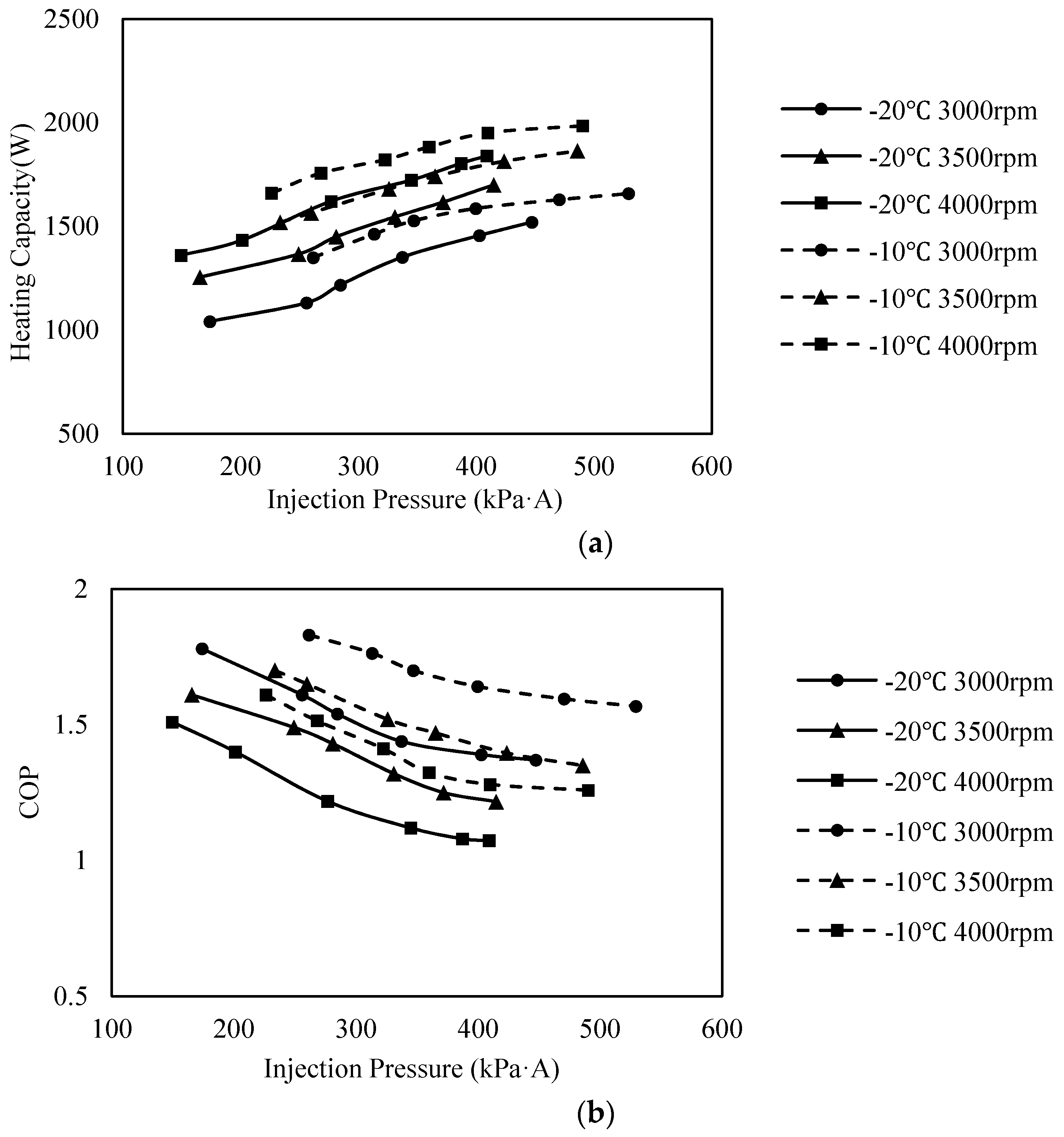
The heating capacities and heating COPs under condition No. 4 and 5 are shown in Figure 4. The heating capacity increases with the injection pressure and compressor speed, while the heating COP decreases with them. Under test condition No. 4, the minimum heating capacity was 1350 W at 3000 rpm and no EVI, while the maximum heating capacity of 1985.7 W was achieved at 4000 rpm, under level 5 of injection pressure. The heating COPs were 1.83 and 1.25, respectively. The heating capacity and heating COP under test condition No. 5 had the same trend with test condition No. 4. The minimum heating capacity was 1041.8 W and the maximum heating capacity was 1840.1 W, while the heating COPs were 1.78 and 1.07, respectively.
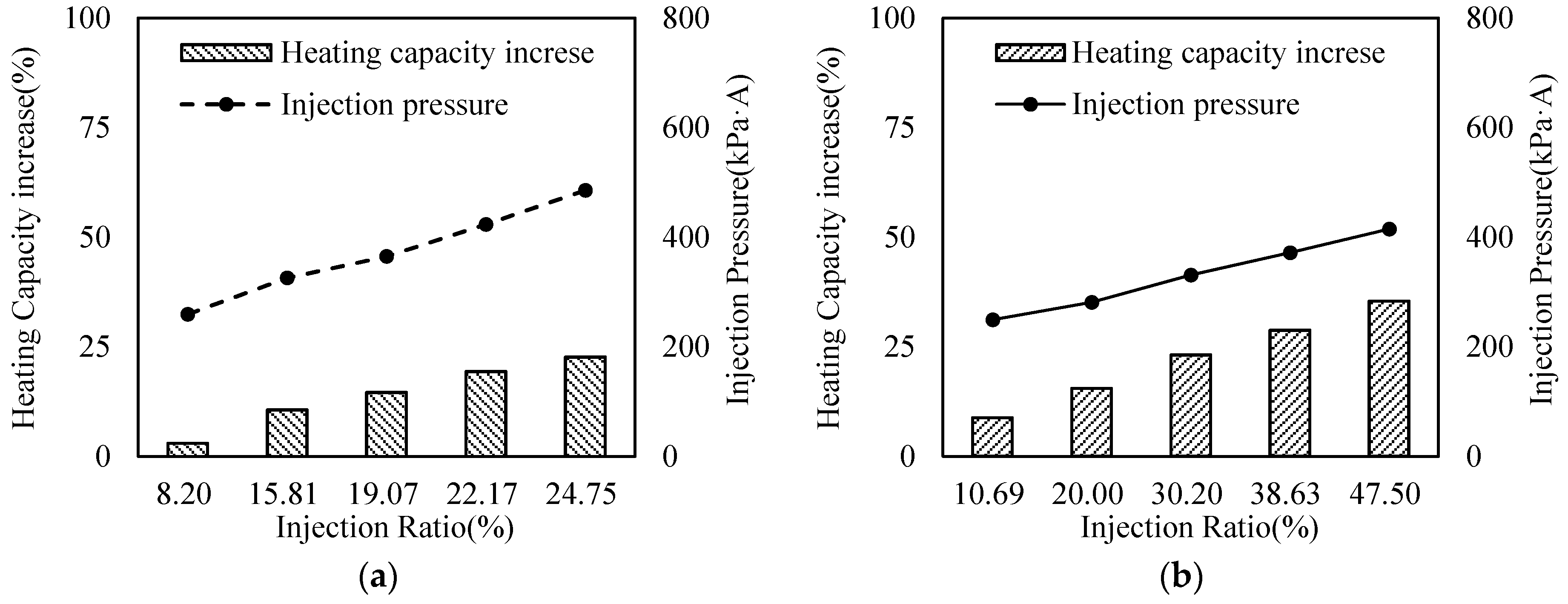
During the injection process, the injected refrigerant enters the compression chamber through the injection port located on the fixed scroll of the compressor. The mass flow rate of injected refrigerant was decided by the characteristics of the injection ports (location, shape, etc.) and the pressure difference between the injection pressure and compressor chamber. As the injection pressure increased, more refrigerant was injected into the compressor, leading to a higher condenser mass flow rate and compression work, which can be seen in Figure 5. The 3500 rpm compressor speed cases of test condition No. 4 and 5 are taken as examples. The injection ratio increased linearly with injection pressure. The same trend can be also found in the heating capacity. The influence of outdoor temperature on EVI performance can be concluded from the comparison of Figure 5a,b. The EVI become less effective under a higher outdoor temperature. The max increase in heating capacity under 3500 rpm decrease from 35.4% to 22% when the outdoor temperature increased from −20 to −10 °C. The injection ratio also decreased due to a higher evaporator mass flow rate.
3.2.2. The Effect of Economizer Capacity
The economizer is a key component in the EVI system. The state of the injected refrigerant is directly influenced by the performance of the economizer, therefore, it further affects the performance of the EVI system. As important as the economizer is, little existing literature can be found on the economizer performance. Some advice can be found on the sizing of economizers [15,21], but most of the advice is quite vague, and the mechanisms of the economizer are not so clearly stated. In this study, the influence of the economizer can be found in the comparison of test conditions No. 4–7, and in the forthcoming description of the analyses which were also conducted.
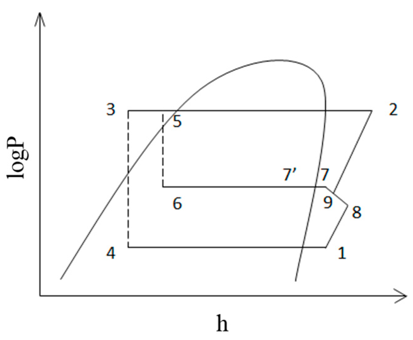
Figure 6 is a sketch of the logP-h diagram of the EVI system. As mentioned before, the EVI enhances the system heating performance by increasing the condenser mass flow rate (point 2 to 5 in Figure 7), while also lowering the refrigerant enthalpy entering the evaporator (point 5 to 3). The cooling capacity generated during the throttling of the injection process is , and the recovered cooling capacity by the economizer is . The expressions of and are as follows:
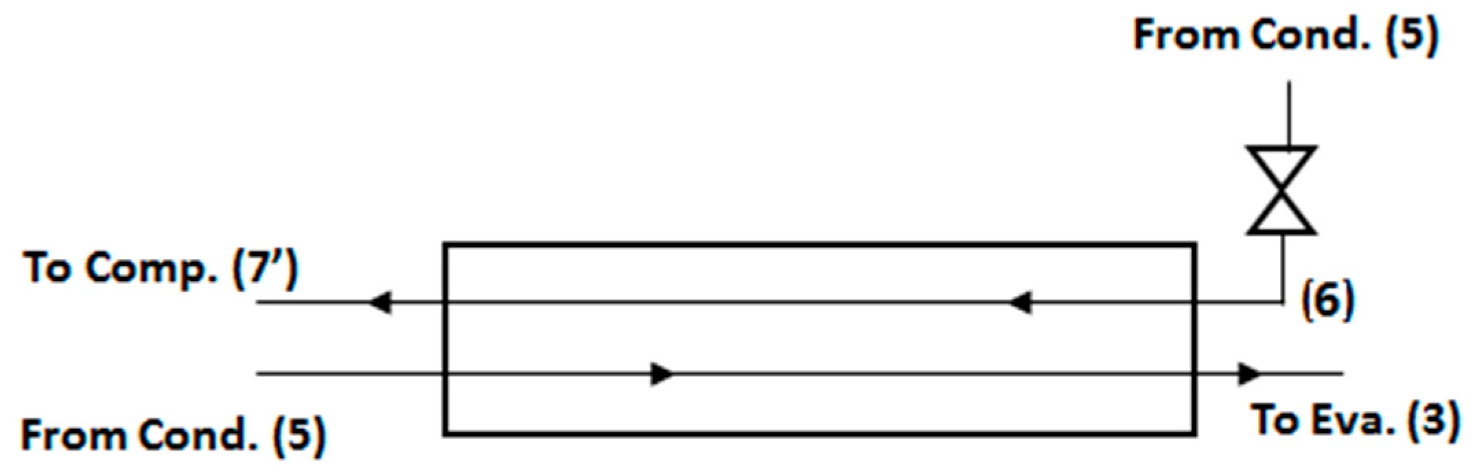
With a higher heat exchange efficiency, the temperature difference between point 3 and 6 will become smaller, which means a larger enthalpy difference between point 1 and 4. As the heating capacity can be expressed as:
the recovered cooling capacity will lead to an increase in and system COP. However, with poor economizer efficiency, little heat exchange will occur between the injection path and the main path. This will lead to a two-phase injection, as no sufficient heat is provided. In the worst case, there will be no heat exchange between two paths of the economizer, and the will become zero. The remains the same in this case, as the mass flow rate of evaporator stays the same [14,15] and point 5 coincides with point 3. The heating capacity will still rise, as the mass flow rate of condenser increases due to injection. The also increases due to the increased mass flow rate. The COP of the system is expressed as:
It can be seen that the will decrease. As such, the increase in economizer efficiency is a benefit to both heating capacity and COP.
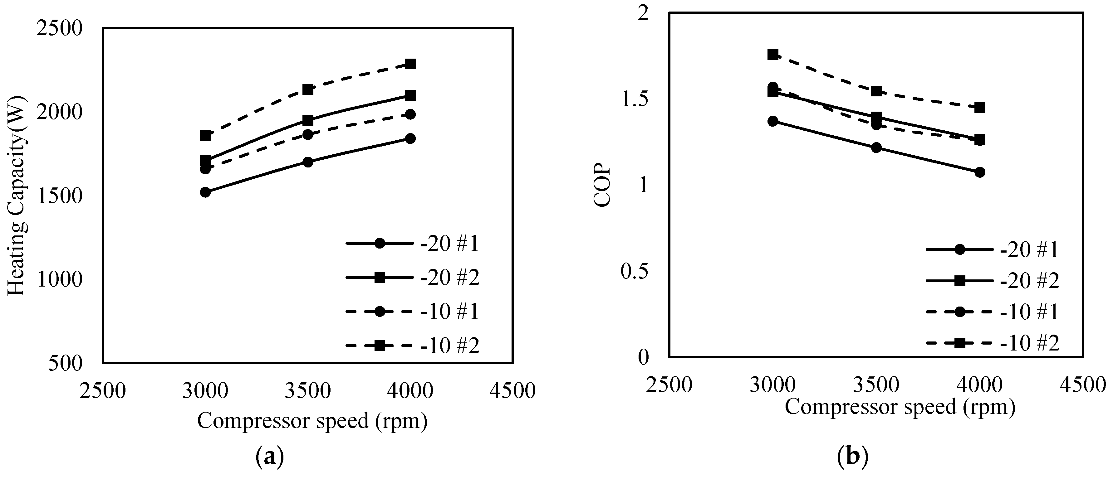
Figure 8 is the result of the comparison of economizer sample #1 and #2 under level 5 injection pressure. It can be seen that with a better-designed economize, an average of 13.6% increase in heating capacity can be achieved, while the average increase in COP is 14.4%.
4. Conclusions
- The optimized TFHX is capable of meeting the performance requirements in both the heating and cooling modes. The simulation showed that under the given conditions, the heat exchange capacities of TFHX were 1.5% higher on average than the MCHX, and the pressure drops were lower; in the heating mode, the drainage performance was much better than the MCHX.
- EVI is a benefit to system heating performance. The heating capacity increased with the injection pressure, and the benefit decreased with the rising ambient temperature. Under −20 °C ambient temperature, an average improvement of 57.7% in heating capacity was achieved. Under −10 °C, the average improvement in heating capacity was 44.1%.
- The performance of the economizer has a great impact on system performance. A 14.4% improvement on average in heating COP and a 13.6% increase in heating capacity can be achieved with a better-designed economizer.
Acknowledgments
This research is supported by the Science and Technology Commission of Shanghai Municipality and SAIC Motor Corporation Limited.
Author Contributions
Ziqi Zhang and Jiangping Chen conceived and designed the experiments; Wanyong Li and Junye Shi performed the experiments and analyzed the data.
Conflicts of Interest
The authors declare no conflict of interest.
Nomenclature
| Cond. | Condenser |
| COP | Coefficient of Performance |
| EV | Electric Vehicle |
| EVI | Economized Vapor Injection |
| Eva. | Evaporator |
| FTVI | Flash Tank Vapor Injection |
| HVAC | Heating, ventilation, air conditioning assembly module |
| HX | Heat Exchanger |
| MCHX | Micro Channel Heat Exchanger |
| PTC | Positive Temperature Coefficient |
| PID | Proportion-Integration-Differentiation |
| UDDS | Urban Dynamometer Driving Schedule |
| TFHX | Tube and Fin Heat Exchanger |
Subscripts
| a | Air |
| comp | Compressor |
| cond | Condenser |
| eva | Evaporator |
| heating | Heating |
| i | In |
| inj | Injection |
| o | Out |
Greek Letter(s)
| Efficiency of Compressor |
References
- Brown, S.; Pyke, D.; Steenhof, P. Electric vehicles: The role and importance of standards in an emerging market. Energy Policy 2010, 38, 3797–3806. [Google Scholar] [CrossRef]
- Rask, E.; Duoba, M.; Lohse-Busch, H.; Walsh, P. Advanced Technology Vehicle Lab Benchmarking-Level 2 (In-Depth); Argonne National Laboratory: Lemont, IL, USA, 2012. [Google Scholar]
- Meyer, J.; Yang, G.; Papoulis, E. R134a Heat Pump for Improved Passenger Comfort. SAE Tech. Pap. 2004. [Google Scholar] [CrossRef]
- Kowsky, C.; Wolfe, E.; Leitzel, L.; Oddi, F. Unitary HPAC System. SAE Int. J. Passeng. Cars-Mech. Syst. 2012, 5, 1016–1025. [Google Scholar] [CrossRef]
- Hirota, Y.; Iwata, R.; Yamauchi, T.; Orihashi, M.; Morita, M. Development of a Compact Adsorption Heat Pump System for Automotive Air Conditioning System. SAE Tech. Pap. 2016. [Google Scholar] [CrossRef]
- Feng, L.; Hrnjak, P. Experimental Study of an Air Conditioning-Heat Pump System for Electric Vehicles. SAE Tech. Pap. 2016. [Google Scholar] [CrossRef]
- Kim, J.H.; Groll, E.A. Performance comparisons of a unitary split system using MicroChannel and fin-tube outdoor coils. ASHRAE Trans. 2003, 109, 219–229. [Google Scholar]
- Benouali, J.; Petitjean, C.; Citti, I.; Beauvis, R.; Delaforge, L. Evaporator-Condenser Improvement and Impact on Heat Pump System Performances for EVs. SAE Tech. Pap. 2014. [Google Scholar] [CrossRef]
- Yan, R.; Shi, J.; Qing, H.; Chen, J.; Song, J. Experimental Study on Heat Exchangers in Heat Pump System for Electric Vehicles. SAE Tech. Pap. 2014. [Google Scholar] [CrossRef]
- Xu, B.; Han, Q.; Chen, J.; Li, F.; Wang, N.; Li, D.; Pan, X. Experimental investigation of frost and defrost performance of microchannel heat exchangers for heat pump systems. Appl. Energy 2013, 103, 180–188. [Google Scholar] [CrossRef]
- Peng, Q.; Du, Q. Progress in Heat Pump Air Conditioning Systems for Electric Vehicles—A Review. Energies 2016, 9, 240. [Google Scholar] [CrossRef]
- Shao, L.L.; Yang, L.; Zhang, C.L. Comparison of heat pump performance using fin-and-tube and microchannel heat exchangers under frost conditions. Appl. Energy 2010, 87, 1187–1197. [Google Scholar] [CrossRef]
- Xu, X.; Hwang, Y.; Radermacher, R. Refrigerant injection for heat pumping/air conditioning systems: Literature review and challenges discussions. Int. J. Refrig. 2011, 34, 402–415. [Google Scholar] [CrossRef]
- Wang, B.; Shi, W.; Han, L.; Li, X. Optimization of refrigeration system with gas-injected scroll compressor. Int. J. Refrig. 2009, 32, 1544–1554. [Google Scholar] [CrossRef]
- Wang, X. Performance Investigation of Two-Stage Heat Pump System with Vapor-Injected Scroll Compressor. Ph.D. Thesis, University of Maryland, College Park, MD, USA, March 2008. [Google Scholar]
- Ma, G.Y.; Zhao, H.X. Experimental study of a heat pump system with flash-tank coupled with scroll compressor. Energy Build. 2008, 40, 697–701. [Google Scholar] [CrossRef]
- Nguyen, M.; Hewitt, N.; Huang, M. Performance evaluation of an air source heat pump using economized vapor injection compressor and flash tank coupled with capillary tubes. In Proceedings of the International Congress of Refrigeration, Beijing, China, 21–26 August 2007.
- Suzuki, T.; Ishii, K. Air Conditioning System for Electric Vehicle. SAE Tech. Pap. 1996. [Google Scholar] [CrossRef]
- Jiang, H.; Aute, V.; Radermacher, R. CoilDesigner: A general-purpose simulation and design tool for air-to-refrigerant heat exchangers. Int. J. Refrig. 2006, 29, 601–610. [Google Scholar] [CrossRef]
- Zhang, C.; Wang, Y.; Chen, J.; Sun, X. Experimental and Numerical Investigations of the Double-Barrel Distributor for Air Conditioner. Int. J. Air-Cond. Refrig. 2015, 23, 1550018. [Google Scholar] [CrossRef]
- Beeton, W.L.; Pham, H.M. Vapor-injected scroll compressors. ASHRAE J. 2003, 45, 22–27. [Google Scholar]
Figure 1.
Sketch of economized vapor injection (EVI) vehicle air conditioning system.
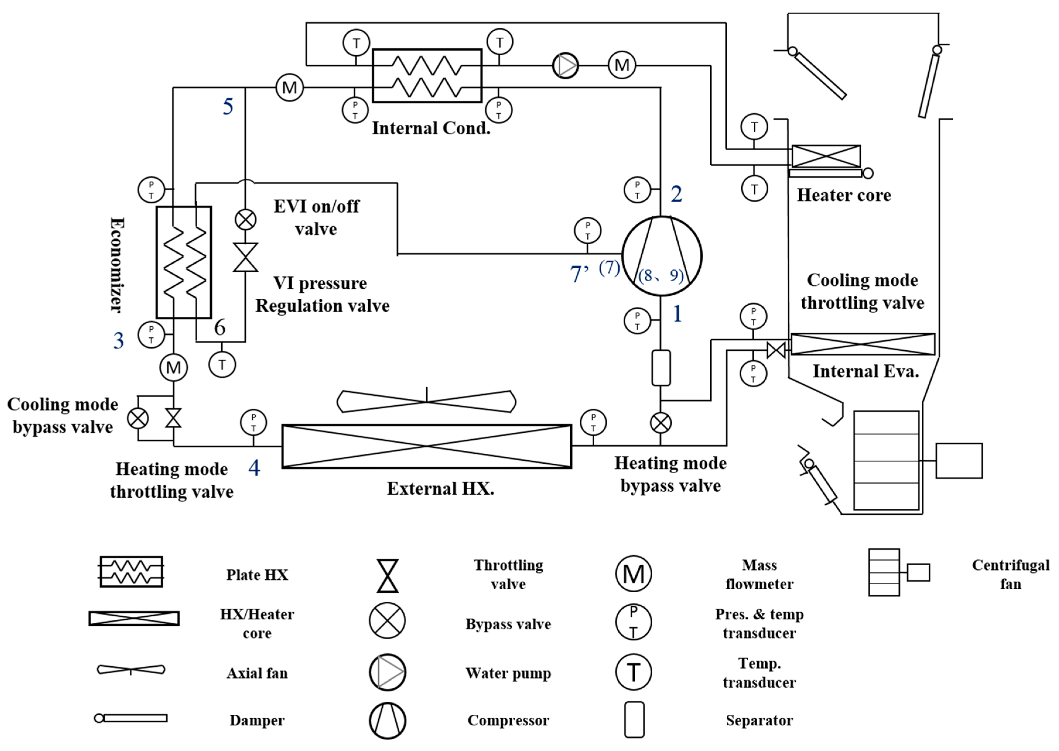
Figure 2.
Simulation results under cooling mode.
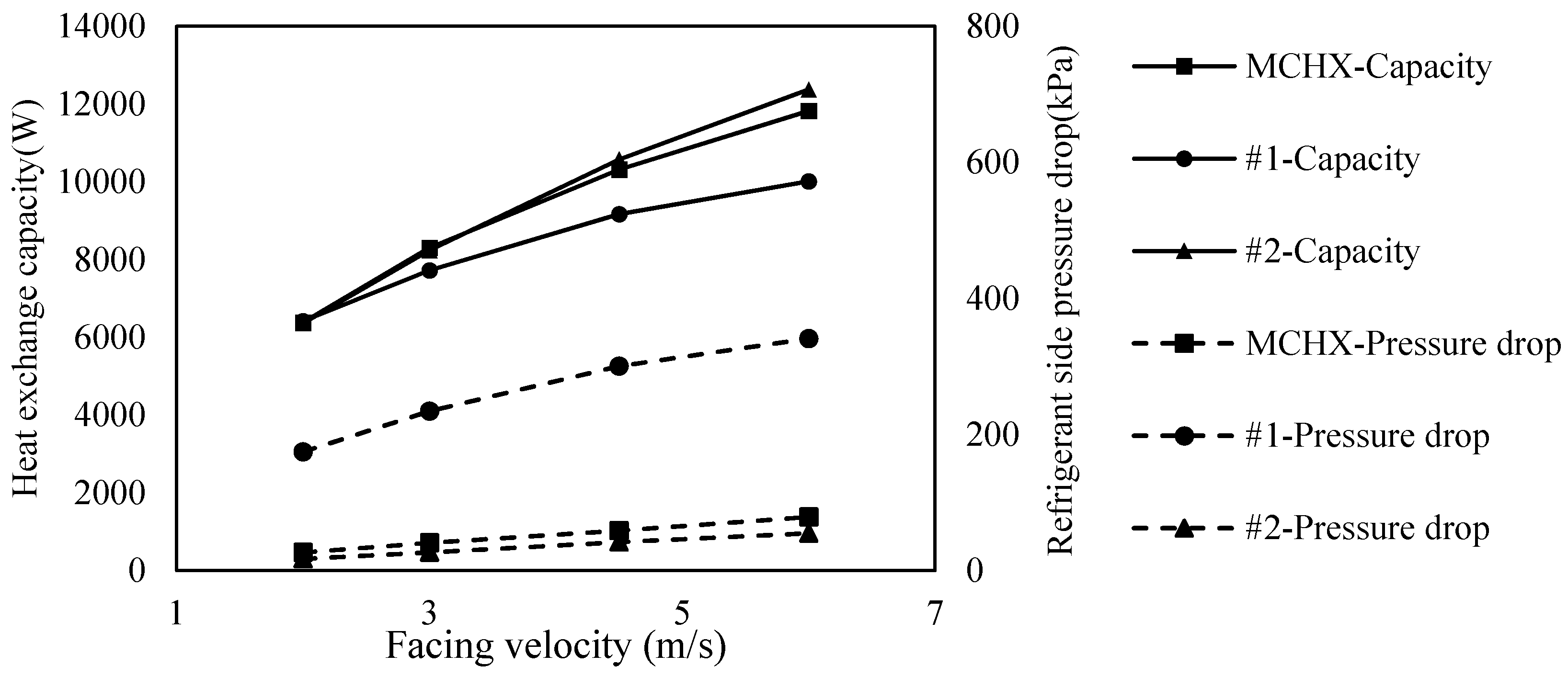
Figure 3.
System performance in heating mode. COP, coefficient of performance.
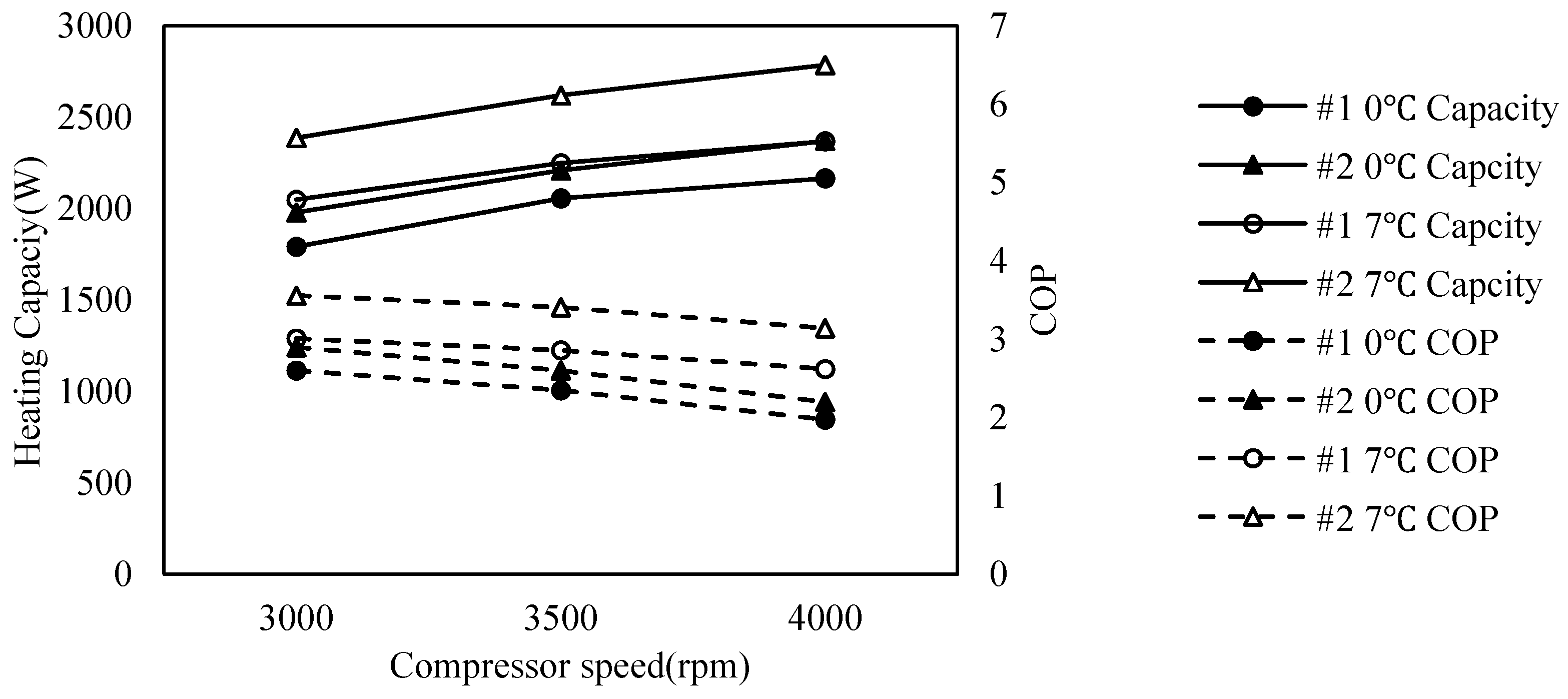
Figure 4.
Heating capacity and COP under different injection pressures. (a) Heating capacity; (b) Heating COP.
Figure 4.
Heating capacity and COP under different injection pressures. (a) Heating capacity; (b) Heating COP.

Figure 5.
Comparison of EVI heating performance to the baseline. (a) Results of test condition No. 4; (b) Results of test condition No. 5.
Figure 5.
Comparison of EVI heating performance to the baseline. (a) Results of test condition No. 4; (b) Results of test condition No. 5.

Figure 6.
LogP-h diagram of EVI system.

Figure 7.
Heat exchange process in economizer.

Figure 8.
System performance comparison of economizer #1 and #2. (a) Heating capacity; (b) Heating COP.
Figure 8.
System performance comparison of economizer #1 and #2. (a) Heating capacity; (b) Heating COP.


Table 1.
System components information. PLHX, plate heat exchanger; MCHX, microchannel heat exchanger; TFHX, tube and fin heat exchanger.
| Components | Information |
|---|---|
| Compressor | EVI scroll type, 27 cm3 |
| Internal Cond. | PLHX, 317 mm (L) × 78 mm (W) × 54 mm (H) |
| Internal Eva. | MCHX, 220 mm (L) × 200 mm (W) × 38 mm (H) |
| External HX | TFHX, 500 mm (L) × 360 mm (W) × 33 mm (H) |
| Heater Core | 220 mm (L) × 150 mm (W) × 40 mm (H) |
| Coolant | 40% glycol |
| Measurement Parameter | Sensor Type | Range | Precision |
|---|---|---|---|
| Temperature | K-type thermocouple | −50–200 °C | ±1 °C |
| Pressure | Piezoresistive pressure sensor | 0–4 MPa | ±10 kPa |
| Mass Flow rate | Coriolis mass flow meter | 0–200 kg/h | ±0.5 kg/h |
| Air speed | Rotary vane anemometer | 0–20 m/s | ±0.05 m/s |
| Current | Ammeter | 0–25 A | ±0.1 A |
| Voltage | Voltmeter | 0–400 V | ±0.01 V |
| No. | Parameters | Value |
|---|---|---|
| 1 | Condenser inlet pressure | 1.6 MPa |
| Condenser inlet superheat | 42 °C | |
| Condenser outlet sub-cooling | 8 °C | |
| Air inlet temperature | 40 °C | |
| Facing velocity | 2, 3, 4.5, 6 m/s |
| No. | Outdoor Air Temperature (°C) | Cabin Air Temperature (°C) | Compressor Rotating Speed (rpm) | Injection Pressure Level | Economizer Sample |
|---|---|---|---|---|---|
| 2 | 7 | 20 | 3000/3500/4000 | - | - |
| 3 | 0 | 20 | - | - | |
| 4 | −10 | 20 | 0–5 | #1 | |
| 5 | −20 | 20 | 0–5 | #1 | |
| 6 | −10 | 20 | 5 | #2 | |
| 7 | −20 | 20 | 5 | #2 |
| Item | MCHX | Item | TFHX#1 | TFHX#2 |
|---|---|---|---|---|
| Tube length (mm) | 495 | Tube length (mm) | 500 | 500 |
| Tube width (mm) | 16 | Tube outer diameter (mm) | 5 | 5 |
| Tube height (mm) | 1 | Number of slabs | 3 | 3 |
| Number of tubes | 38 | Tubes per slab | 18 | 18 |
| Number of passes | 4 | Tube arrangement | 3 in 3 out | 6 in 6 out |
| Fin width (mm) | 16.4 | Row spacing (mm) | 19 | 19 |
| Fin height (mm) | 5.4 | Tube spacing (mm) | 11 | 11 |
© 2016 by the authors; licensee MDPI, Basel, Switzerland. This article is an open access article distributed under the terms and conditions of the Creative Commons Attribution (CC-BY) license (http://creativecommons.org/licenses/by/4.0/).
Share and Cite
MDPI and ACS Style
Zhang, Z.; Li, W.; Shi, J.; Chen, J. A Study on Electric Vehicle Heat Pump Systems in Cold Climates. Energies 2016, 9, 881. https://doi.org/10.3390/en9110881
AMA Style
Zhang Z, Li W, Shi J, Chen J. A Study on Electric Vehicle Heat Pump Systems in Cold Climates. Energies. 2016; 9(11):881. https://doi.org/10.3390/en9110881
Chicago/Turabian StyleZhang, Ziqi, Wanyong Li, Junye Shi, and Jiangping Chen. 2016. "A Study on Electric Vehicle Heat Pump Systems in Cold Climates" Energies 9, no. 11: 881. https://doi.org/10.3390/en9110881
Note that from the first issue of 2016, this journal uses article numbers instead of page numbers. See further details here.