
Master–Slave Based Hierarchical Control for a Small Power DC-Distributed Microgrid System with a Storage Device

Abstract
:1. Introduction
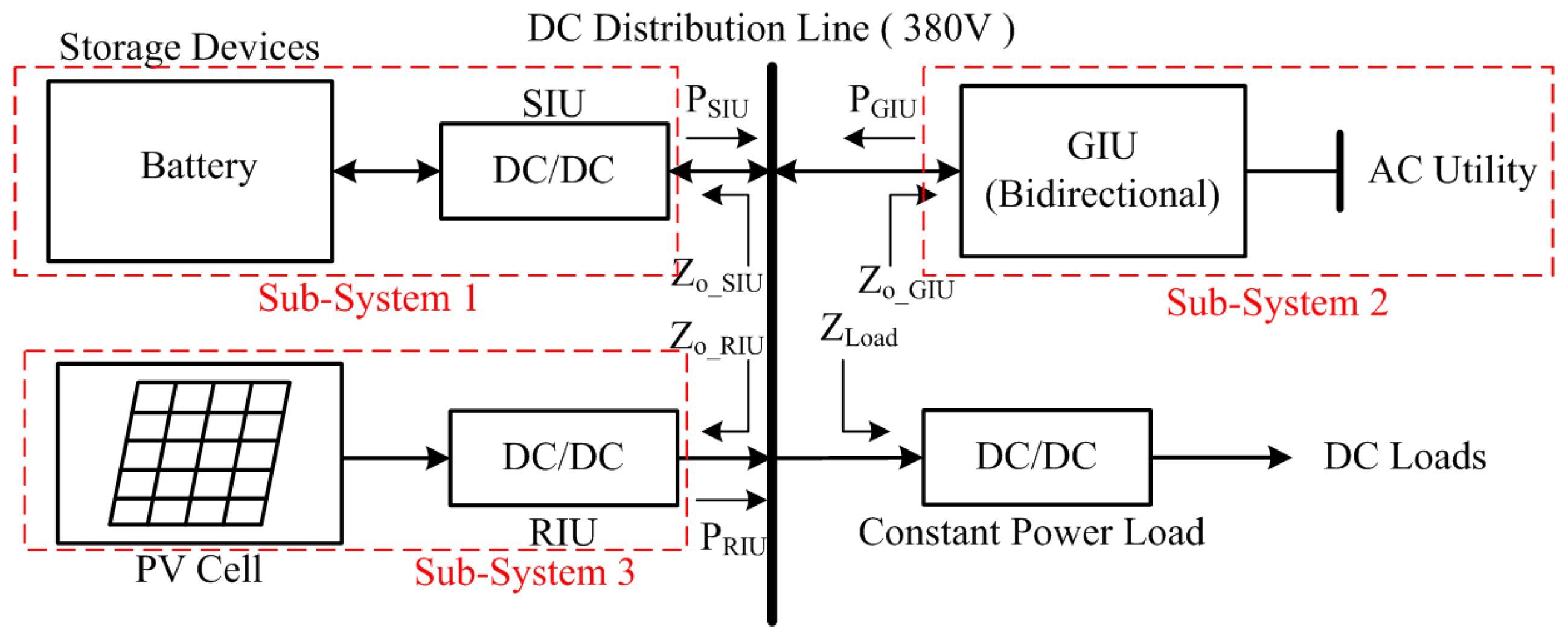
2. Structure and Operational Principles of the Proposed Master–Slave Method
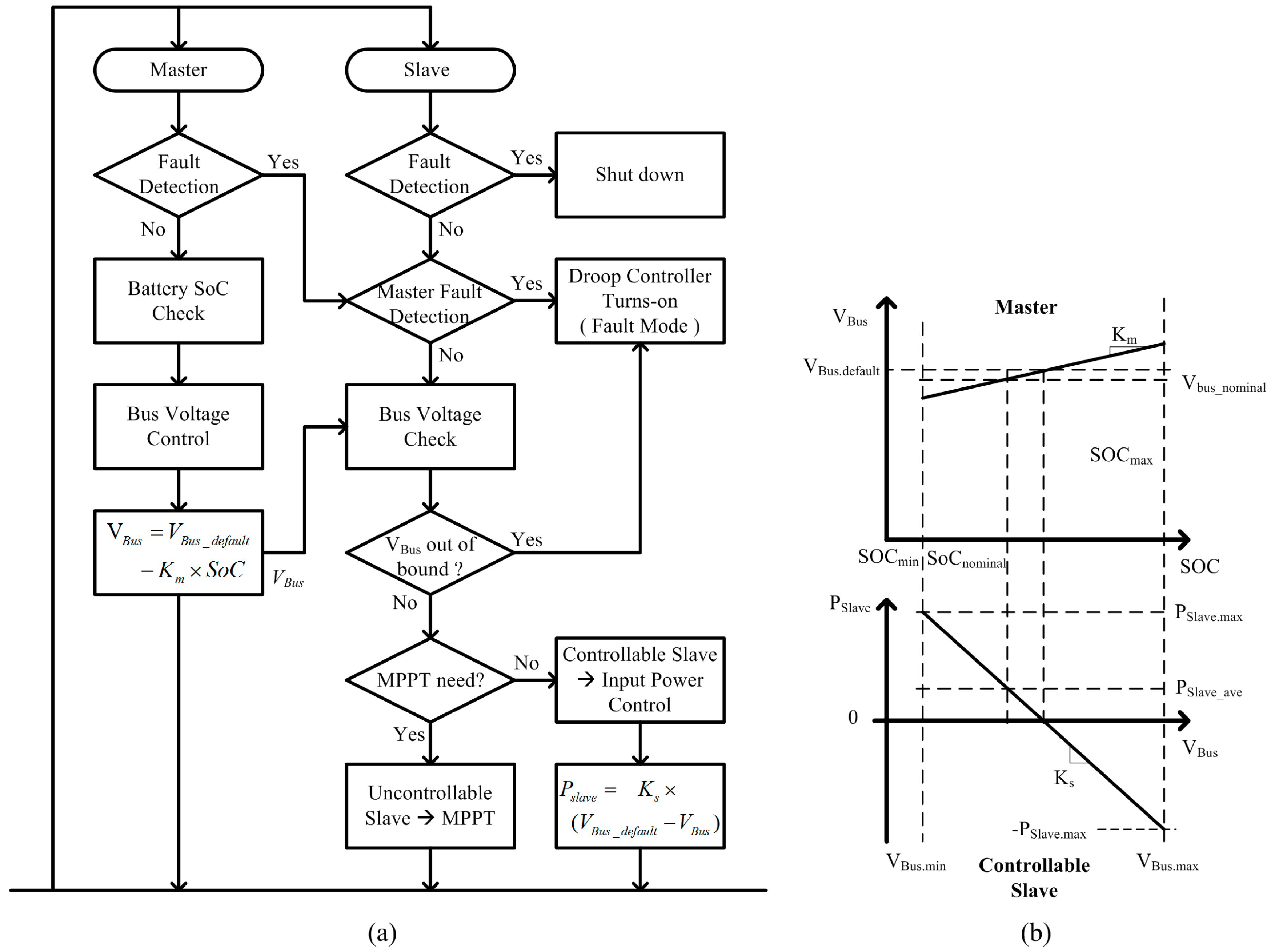
3. Master–Slave-Based Hierarchical Control Method
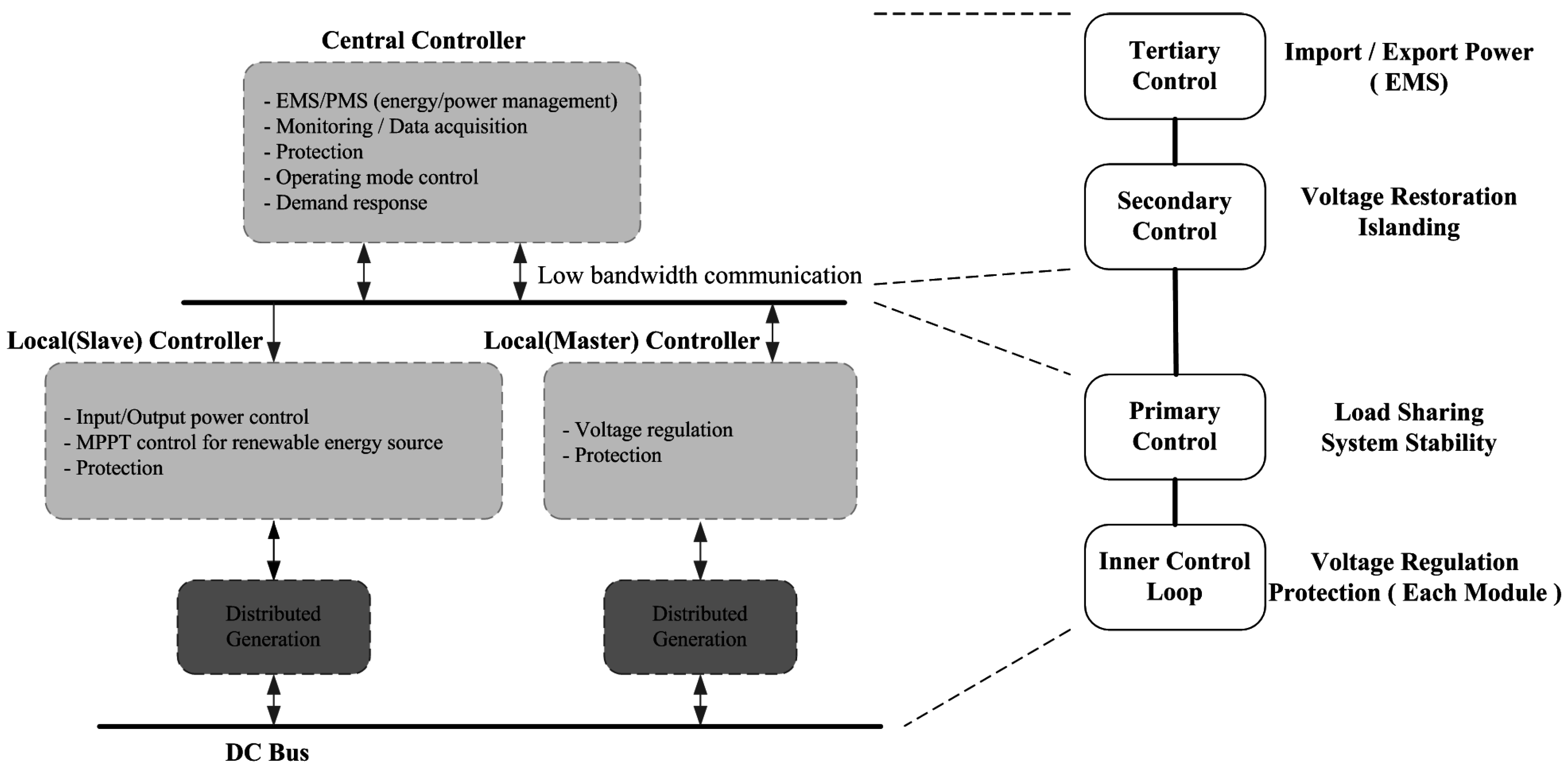
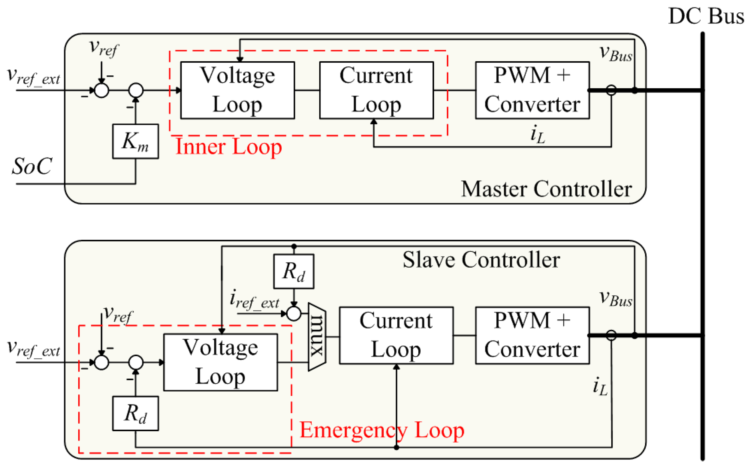
- Local Controller (inner control loop + primary control): bus voltage regulation, current and voltage control loop design, system stability issues, protection of each module, etc.
- Central Controller (secondary control + tertiary control): energy management of system, supply and demand prediction, bus quality control using bus voltage regulation, etc.
3.1. Local Controller
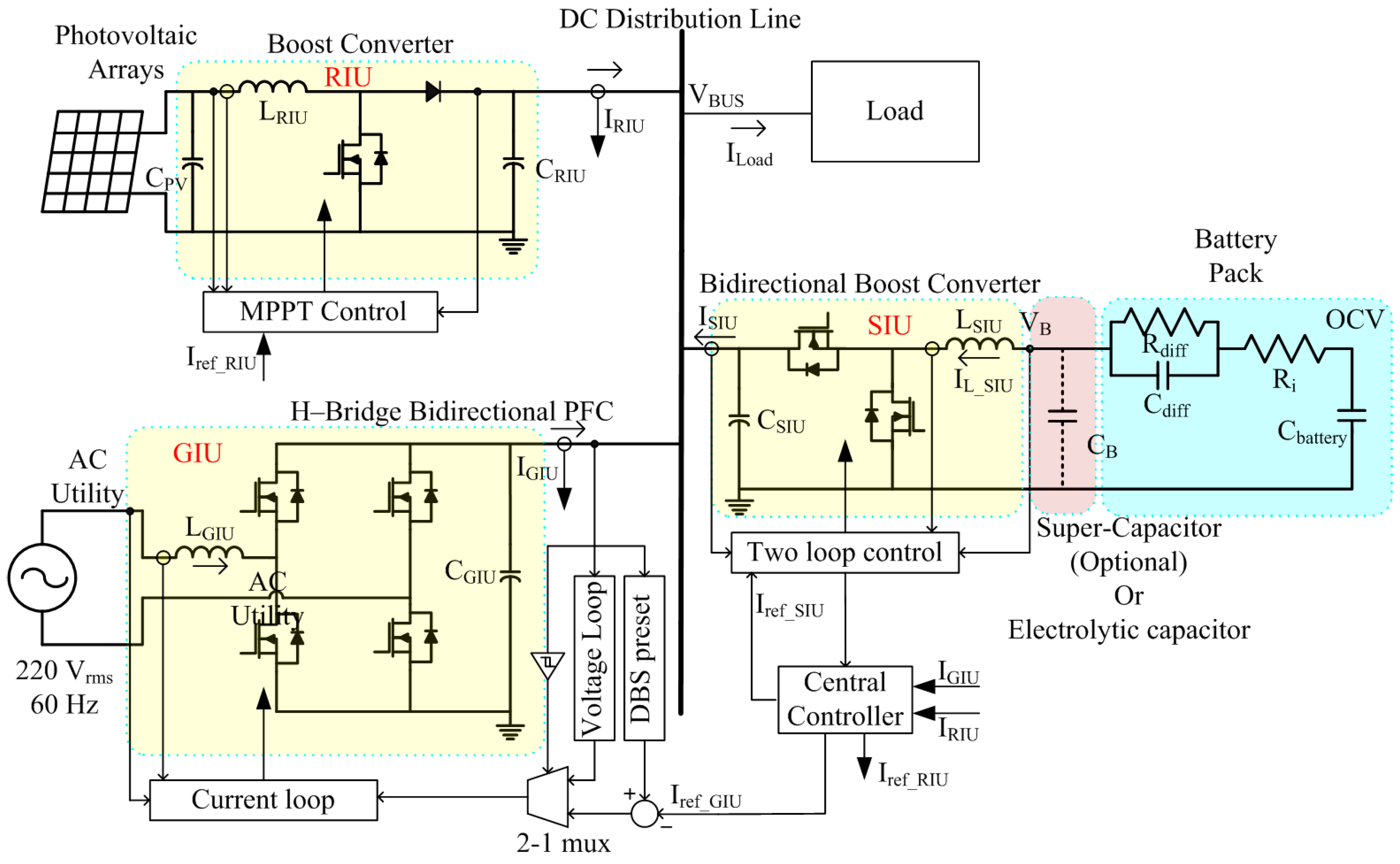
3.2. Central Controller
4. Simulation and Experimental Results
4.1. Simulation Results
4.2. Experimental Results
5. Conclusions
Acknowledgments
Author Contributions
Conflicts of Interest
Abbreviations
| GIU | Grid Interface Unit. |
| SIU | Storage Interface Unit. |
| RIU | Renewable Interface Unit. |
| PGIU | Power transferred through GIU |
| PSIU | Power transferred through SIU |
| PRIU | Power transferred through RIU |
| PGIU_ave | Daily average power transferred through GIU |
| VBus | DC bus voltage |
| VBus_nominal | Daily nominal dc bus voltage |
| Gvg | Small signal transfer function of input voltage to output voltage |
| Gig | Small signal transfer function of input voltage to inductor current |
| Gvi | Small signal transfer function of output current to output voltage |
| Gvd | Small signal transfer function of duty to output voltage |
| Gid | Small signal transfer function of duty to inductor current |
| Gii | Small signal transfer function of output current to inductor current |
| Hi | Current loop controller function |
| Hv | Voltage loop controller function |
| Rd | Droop gain |
| Gvi_closed | Gvi when current and voltage loop are closed |
| Rd_closed | Rd when current and voltage loop are closed |
| Ti | Current loop gain |
| Tv | Voltage loop gain |
| Zo | Output impedance |
| Zo_RIU | Output impedance of the RIU |
| Zo_SIU | Output impedance of the SIU |
| Zo_GIU | Output impedance of the GIU |
| fsw | Switching frequency of the converter |
| fo | Frequency of utility grid |
| Co | Output capacitor |
| IL_GIU | Inductor current of GIU |
| IL_SIU | Inductor current of SIU |
| ILoad | Total load current |
| ISIU | Output current of SIU |
| IGIU | Output current of GIU |
| IRIU | Output current of RIU |
| fBW | Closed loop controller bandwidth. |
Appendix
| Battery pack specification |
| 1. Cell: ICR18650-26F, Samsung SDI |
| Typical voltage: 3.7 V |
| Maximum voltage: 4.45 V |
| Minimum voltage: 2.97 V |
| Cbattery: 421,200 F |
| Ri: 0.1524 Ω |
| Rdiff: 0.0538 Ω |
| Cdiff: 6980 F |
| Capacity: 2.6 Ah-9.62 Wh |
| 2. Pack: 54 Series-2 Parallel Stack |
| Typical voltage: 200 V |
| Cbattery: 15,600 F |
| Ri: 4.1148 Ω |
| Rdiff: 1.4526 Ω |
| Cdiff: 258.5185 F |
| Capacity: 5.4 Ah-1 kWh |
References
- Bloemink, J.M.; Green, T.C. Benefits of Distribution-Level Power Electronics for Supporting Distributed Generation Growth. IEEE Trans. Power Deliv. 2013, 28, 911–919. [Google Scholar] [CrossRef]
- Driesen, J.; Katiraei, F. Design for Distributed Energy Resources. IEEE Power Energy Mag. 2008, 6, 30–40. [Google Scholar]
- Pepermans, G.; Driesen, J.; Haeseldonckx, R.; D’haeseleer, W. Distributed generation: Definition, Benefits and Issues. Energy Policy 2005, 33, 787–798. [Google Scholar] [CrossRef]
- Hatziargyriou, N.; Asano, H.; Iravani, R.; Marnay, C. Microgrids. IEEE Power Energy Mag. 2007, 5, 78–94. [Google Scholar] [CrossRef]
- Sechilariu, M.; Locment, F.; Wang, B. Photovoltaic Electricity for Sustainable Building Efficiency and Energy Cost Reduction for Isolated Microgrid. Energies 2015, 8, 7945–7967. [Google Scholar] [CrossRef]
- Hammerstrom, D.J. AC versus DC Distribution Systems-Did We Get It Right? In Proceedings of the Power Engineering Society General Meeting, Tampa, FL, USA, 24–28 June 2007; pp. 1–5.
- Huey, P.; Lo, E.; Pong, B. DC Electrical Distribution Systems in Buildings. In Proceedings of the International Conference on Power Electronics Systems and Applications, Hong Kong, China, 12–14 November 2006; pp. 115–119.
- Karlsson, P. DC Distributed Power Systems: Analysis, Design and Control for a Renewable Energy Systems. Ph.D. Thesis, Department of Industrial Electrical Engineering and Automation, Lund University, Lund, Sweden, 2002. [Google Scholar]
- Pratt, A.; Kumar, P.; Aldridge, T.V. Evaluation of 400 V DC Distribution in Telco and Data Centers to Improve Energy Efficienty. In Proceedings of the International Telecommunications Energy Conference, Rome, Italy, 30 September–4 October 2007; pp. 32–37.
- Baran, M.E.; Mahajan, N.R. DC Distribution for Industrial Systems: Opportunities and Challenges. IEEE Trans. Ind. Appl. 2003, 39, 1596–1601. [Google Scholar] [CrossRef]
- Seo, G.S.; Baek, J.B.; Choi, K.S.; Bae, H.; Cho, B. Modeling and Analysis of DC Distribution Systems. In Proceedings of the International Conference on Power Electronics and ECCE Asia, Jeju, Korea, 30 May–3 June 2011; pp. 223–227.
- Johnson, B.K.; Lasseter, R.H.; Alvarado, F.L.; Adapa, R. Expandable multi-terminal DC Systems Based on Voltage Droop. IEEE Trans. Power Deliv. 1993, 8, 1926–1932. [Google Scholar] [CrossRef]
- Guerrero, J.M.; Vasquez, J.C.; Matas, J.; de Vicuna, L.G.; Castilla, M. Hierarchical Control of Droop-Controlled AC and DC Microgrids—A General Approach toward Standardization. IEEE Trans. Ind. Electron. 2011, 58, 158–172. [Google Scholar] [CrossRef]
- Cao, X.; Zhong, Q.C.; Ming, W.L. Ripple Eliminator to Smooth DC-Bus Voltage and Reduce the Total Capacitance Required. IEEE Trans. Ind. Electron. 2015, 62, 2224–2235. [Google Scholar] [CrossRef]
- Dong, D. AC-DC Bus-interface Bi-directional Converters in Renewable Energy Systems. Ph.D. Thesis, Electrical Engineering, University of Virginia Polytechnic Institute and State University, Blacksburg, VA, USA, July 2012. [Google Scholar]
- Magro, M.C.; Mariscotti, A.; Pinceti, P. Definition of Power Quality Indices for DC Low Voltage Distribution Networks. In Proceedings of the Instrumentation and Measurement Technology Conference, Sorrento, Italy, 24–27 April 2006; pp. 1885–1888.
- Electric Power Research Institute (EPRI). DPQ Executive Summary; EPRI: Pal Alto, CA, USA, 2003. [Google Scholar]
- Tsikalakis, A.G.; Hatziargyriou, N.D. Centralized Control for Optimizing Microgrids Operation. IEEE Trans. Energy Convers. 2008, 23, 241–248. [Google Scholar] [CrossRef]
- Luo, S.G.; Ye, Z.G.; Lin, R.L.; Lee, F.C. A classification and evaluation of paralleling methods for power supply modules. In Proceedings of the Power Electronics Specialists Conference, Charleston, VA, USA, 1 July 1999; pp. 901–908.
- Schonberger, J.K. Distributed Control of a Nanogrid Using DC Bus Signaling. Ph.D. Thesis, Electrical and Electronic Engineering, University of Canterbury, Chiristchurch, UK, May 2005. [Google Scholar]
- Cvetkovic, I. Modeling, Analysis and Design of Renewable Energy Nanogrid Systems. Master’s Thesis, Electrical Engineering, Virginia Polytechnic Institute and State University, Virginia, VA, USA, July 2010. [Google Scholar]
- Chun, C.Y.; Baek, J.; Seo, G.S.; Cho, B.H.; Kim, J. Current Sensor-less State-of-charge Estimation Algorithm for Lithium-Ion Batteries Utilizing Filtered Terminal Voltage. J. Power Sources 2015, 273, 255–263. [Google Scholar] [CrossRef]
- Baochao, W.; Sechilariu, M.; Locment, F. Intelligent DC Microgrid with Smart Grid Communications: Control Strategy Consideration and Design. IEEE Trans. Smart Grid 2012, 3, 2148–2156. [Google Scholar]
- Anand, S.; Fernandes, B.G.; Guerrero, J. Distributed Control to Ensure Proportional Load Sharing and Improve Voltage Regulation in Low-Voltage DC Microgrids. IEEE Trans. Power Electorn. 2013, 28, 1900–1913. [Google Scholar] [CrossRef]
- Gavriluta, C.; Candela, J.I.; Rocabert, J.; Luna, A.; Rodriguez, P. Adaptive Droop for Control of Multiterminal DC Bus Integrating Energy Storage. IEEE Trans. Power Deliv. 2015, 30, 16–24. [Google Scholar] [CrossRef] [Green Version]
- Whaite, S.; Grainger, B.; Kwasinsky, A. Power Quality in DC Power Distribution Systems and Microgrids. Energies 2015, 8, 4378–4399. [Google Scholar] [CrossRef]
- Saberbari, E.; Saboori, H. Net-Zero Energy Building Implementation through a Grid-Connected Home Energy Management System. In Proceedings of the 19th Electrical Power Distribution Conference (EPDC2014), Tehran, Iran, 6–7 May 2014.
- Aste, N.; Adhikari, R.S.; Del Pero, C. Photovoltaic Technology for Renewable Electricity Production: Towards Net Zero Energy Buildings. In Proceedings of the International Conference on Clean Electrical Power (ICCEP), Ischia, Italy, 14–16 June 2011.


| Unit Type | Symbol | Value | Note |
|---|---|---|---|
| GIU | fsw_GIU | 18 kHz | Switching frequency |
| LGIU | 4 mH | - | |
| CGIU | 1 mF | - | |
| fBW_GIU | 1 kHz | Cut-off frequency of current controller | |
| SIU | fsw_SIU | 50 kHz | Switching frequency |
| LSIU | 740 µH | - | |
| CSIU | 47 µF | - | |
| CB | 100 µF | - | |
| fBW_SIU | 700 Hz | Cut-off frequency of voltage controller | |
| Battery | OCV | 150–240 V | Open circuit voltage range |
| Ri | 4.115 Ω | - | |
| Rdiff | 1.453 Ω | - | |
| Cdiff | 258.52 F | - | |
| Cbattery | 15,600 F | - | |
| RIU | fsw_RIU | 50 kHz | Switching frequency |
| CPV | 100 µF | - | |
| CRIU | 100 µF | - | |
| LRIU | 500 µH | - | |
| fBW_RIU | 450 Hz | Cut-off frequency of MPPT voltage controller | |
| PV | VPV | 200 V | Open circuit voltage |
| 150 V | MPP voltage | ||
| IPV | 8.4 A | Short circuit current | |
| 7 A | MPP current |
| Symbol | Value | Note |
|---|---|---|
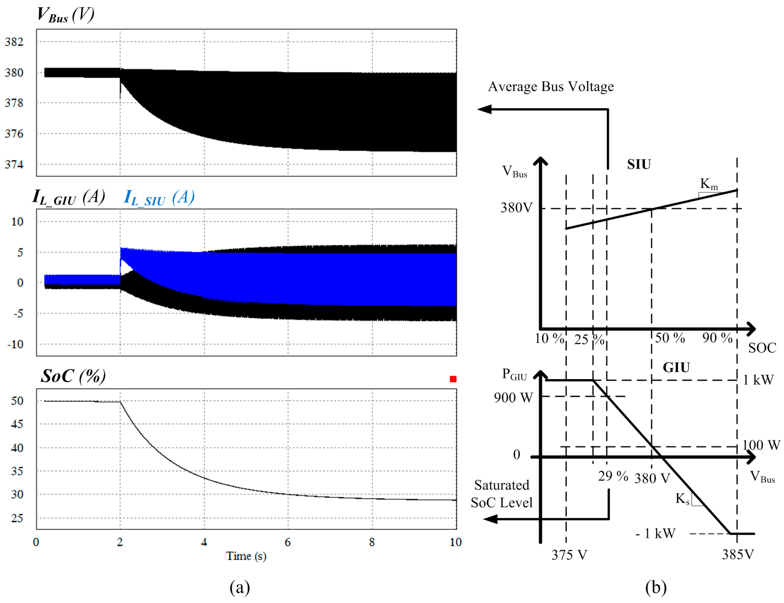
| Km | 0.125 | Master coefficient |
| Ks | −2 | Slave coefficient |
| Vbus_nominal | 380 V | Nominal bus voltage |
| PGIU.ave | 100 W | Standard point value |
© 2016 by the authors; licensee MDPI, Basel, Switzerland. This article is an open access article distributed under the terms and conditions of the Creative Commons Attribution (CC-BY) license (http://creativecommons.org/licenses/by/4.0/).
Share and Cite
Lee, S.-W.; Cho, B.-H. Master–Slave Based Hierarchical Control for a Small Power DC-Distributed Microgrid System with a Storage Device. Energies 2016, 9, 880. https://doi.org/10.3390/en9110880
Lee S-W, Cho B-H. Master–Slave Based Hierarchical Control for a Small Power DC-Distributed Microgrid System with a Storage Device. Energies. 2016; 9(11):880. https://doi.org/10.3390/en9110880
Chicago/Turabian StyleLee, Seung-Woon, and Bo-Hyung Cho. 2016. "Master–Slave Based Hierarchical Control for a Small Power DC-Distributed Microgrid System with a Storage Device" Energies 9, no. 11: 880. https://doi.org/10.3390/en9110880