1. Introduction
One of the challenges of the last few decades is to develop renewable energy sources able to provide reliable and continuous base-load power, as well as peak-load power when it is needed to match supply demand.
For renewable energies, a high level of unused capacity comes from the high variability of the source over time. Their intermittent nature has a large impact: low capacity factors, low flexibility and higher amortization costs.
Among all of the technologies available to produce electrical power, many efforts are investigating thermal to electrical conversion, but the results are currently limited, in conversion efficiencies, by the operation temperature, which is often below 800 K. There is therefore the necessity to reach very high temperature operations, and this is one of the aims of the “HRC-Power” project, which proposes such concepts, adding also the capability to work with both combustion and solar concentration with miniaturized items.
Miniaturization, mandatory to overcome the batteries energy density limits, may lead to incomplete combustion and flame instability [
1,
2]. Some strategies have been adopted to overcome these drawbacks, such as using quench-resistant fuels, liquid-fuel-film combustors [
3,
4,
5], swirling chambers [
6,
7,
8] and catalytic surfaces [
9].
Among the available works, the one reported in [
10] is worthy of mention; this is an experimental work on a device (9.5 mm × 60 mm) that adopts tangential air inlets and an axial fuel (methane) inlet by a 6-mm ID duct or pre-chamber; the exhaust duct is axial, as well. Several configurations are investigated to increase the chemical combustion efficiency, such us a porous cap (enhances mixing) and reversed tubes (enhances pre-heating and internal chamber mixing), obtaining an overall efficiency of about 1% (electrical-chemical power ratio).
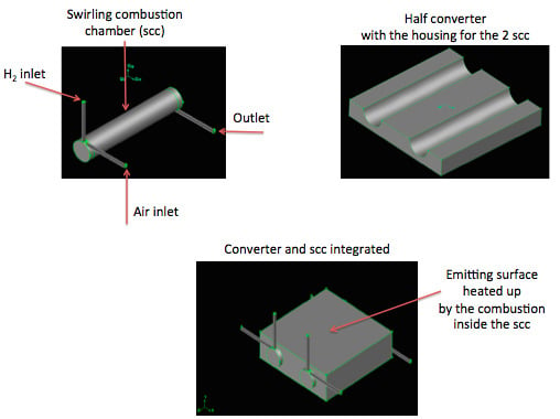
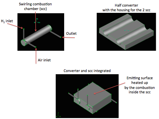
The present paper reports an energy converter, smaller than half the one in [
10], which conceptually is an emitting parallelepiped with two separated swirling combustion chambers inside; the swirling motion increases the residence time, enhancing mixing, and then improves the overall efficiency [
6,
7,
8].
The two chambers burn H2/air for a total injected power of 400 W at 1 atm of pressure; they heat up the emitting surfaces of the converter, which, consequently, release heat power to the external environment.
The purpose of this paper is, therefore, the analysis of the thermo-fluid dynamics behavior inside the combustion chambers and throughout the entire device. In particular, nine configurations, which differ in the chamber diameters and equivalence ratios, are reported (see
Section 2 and
Section 3).
The analysis is carried out comparing the internal reacting flows, with a focus on chemical efficiency, the fluid-structure interaction, the average temperature and the relative delta, on the emitting surfaces together with the relative thermal power delivered to the external environment (
Section 4).
The addition of future strategies, apt at improving the overall converter’s energy efficiency, completes the work; this may be considered the path to follow in order to obtain definitive and complete results to be provided to the manufacturing industry and then everyday usage (see
Section 5).
This study, and its results, is part of the “HRC Power” project (cordis.europa) [
11], which aims to develop hybrid sources of power (Harnessing hybrids, Pan European Networks) [
12].
2. Energy Converter, Operating and Boundary Conditions
Three converters with two non-premixed separated swirling meso-scale combustors are shown in
Figure 1,
Figure 2 and
Figure 3, as a function of three length/diameter ratios (
Z/
D), that is
Z/
D = 11, 5 and 3.
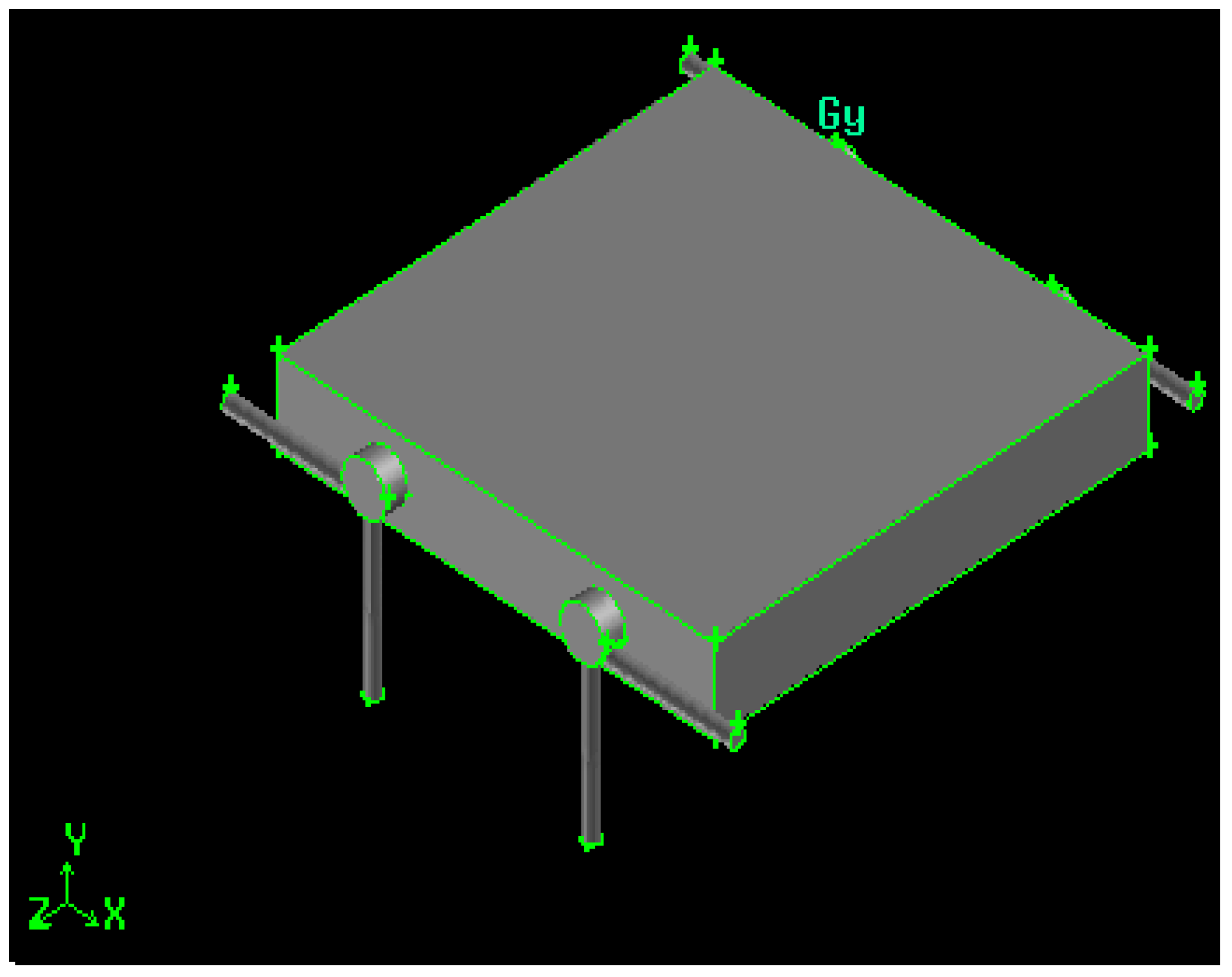
Figure 1.
Swirling combustor converter, length/diameter ratio (Z/D) = 11.
Figure 1.
Swirling combustor converter, length/diameter ratio (Z/D) = 11.
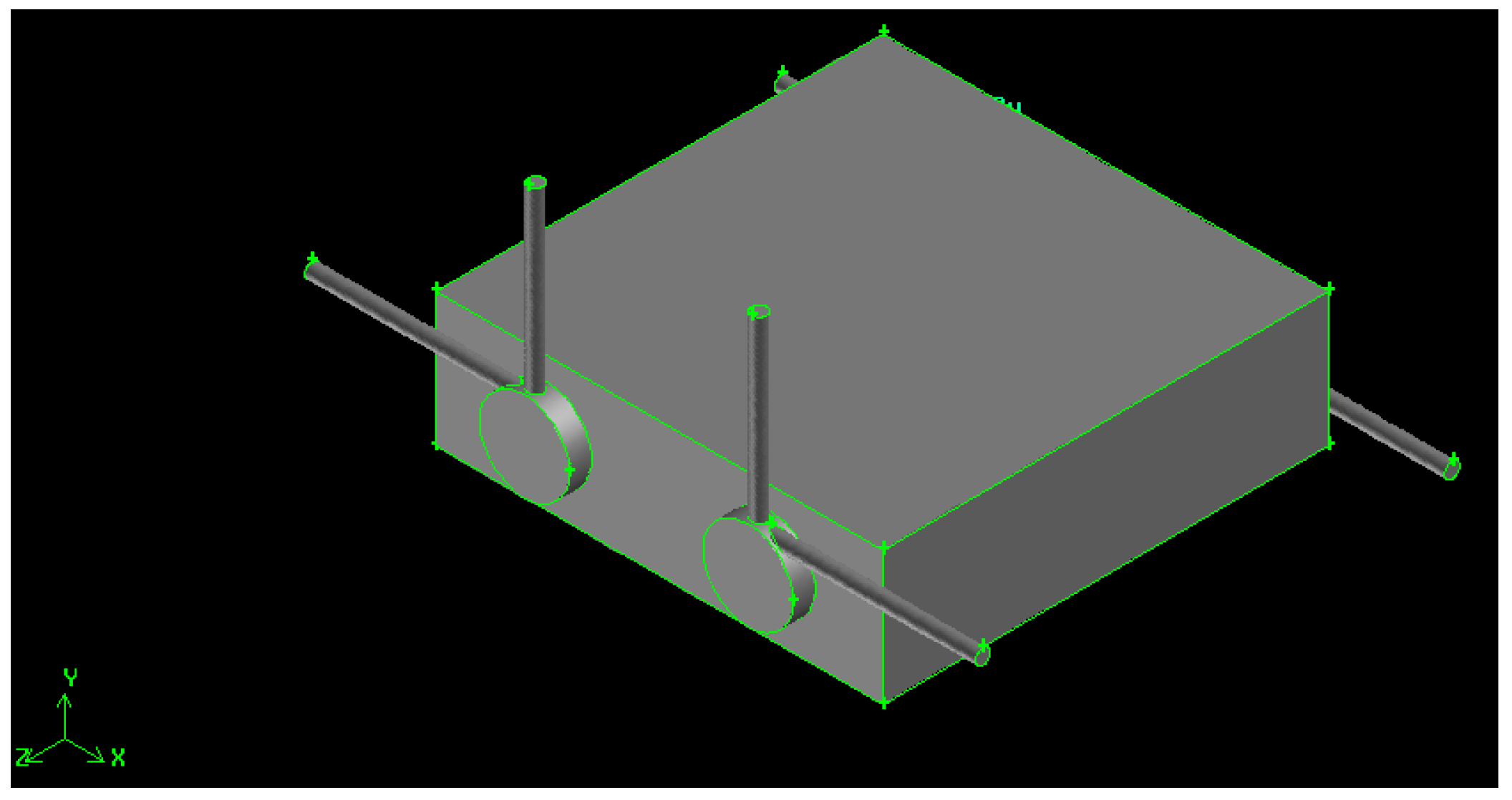
Figure 2.
Swirling combustor converter, Z/D = 5.
Figure 2.
Swirling combustor converter, Z/D = 5.
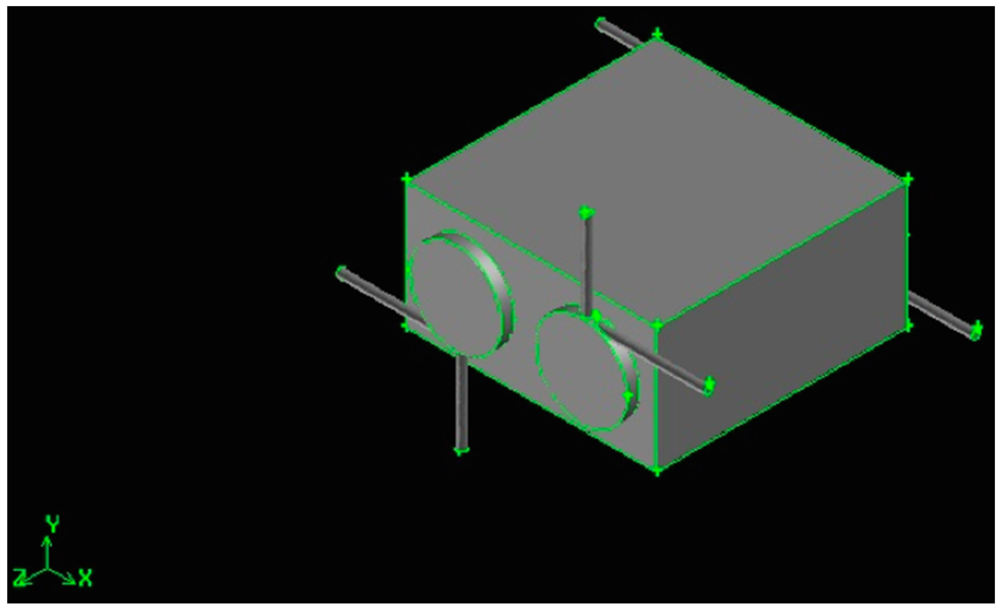
Figure 3.
Swirling combustor converter, Z/D = 3.
Figure 3.
Swirling combustor converter, Z/D = 3.
The converters have x-z fixed dimensions (30 mm × 30 mm), while the y dimension depends on the chambers’ diameter. It is always 3 mm deeper than the diameter itself, then the y-dimension is 6 mm for the 3 mm diameter (Z/D = 11), 9 mm for the 6 mm diameter (Z/D = 5) and 14 mm for the 11 mm diameter (Z/D = 3).
The cylindrical combustion chamber length is fixed to 33 mm, with a total volume of about 233 mm3, for Z/D = 11,932 mm3, for Z/D = 5, and 3134 mm3, for Z/D = 3.
The two combustion chambers are separated, then two, co-planar hydrogen and air inlet ducts are present (a connected configuration will be presented in a future paper). The distance between the two chambers is 12 mm, 9 mm and 4 mm, respectively, for the Z/D = 11, Z/D = 5 and Z/D = 3 configurations.
The gaseous hydrogen is injected in the radial direction, at 90° with respect to the air flow, to improve mixing and generate a swirling motion, enhanced by the higher air kinetic energy, injected tangentially. Both air and fuel injection orifices, together with the exhaust duct, are 1 mm in diameter to ease the drilling phase. Gases exhaust in the tangential direction, and this geometrical solution enhances mixing by the definition of recirculation bubbles [
8].
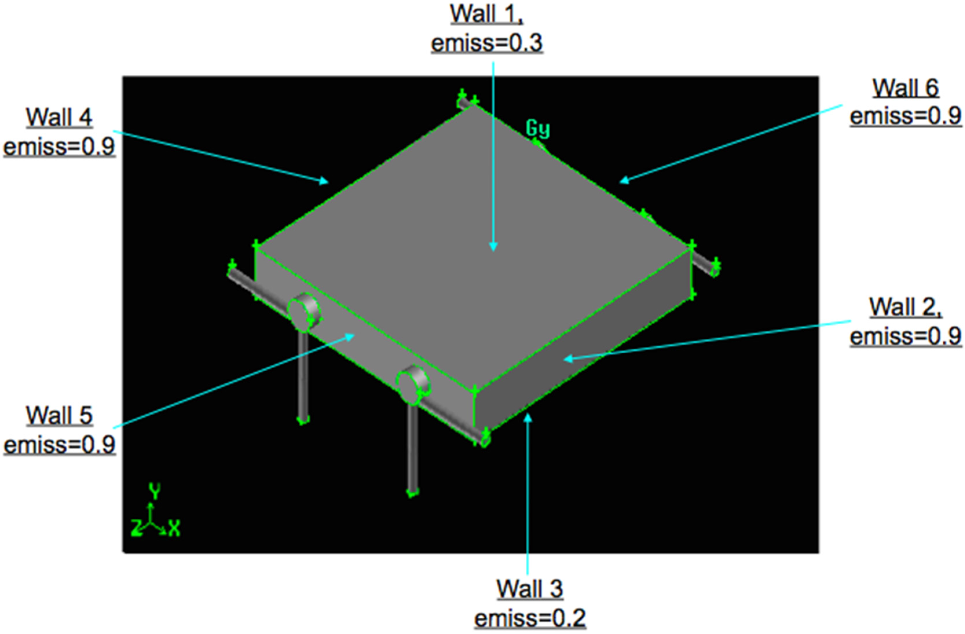
The internal chamber walls are coupled with the SiC block, in order to permit the combustion products to heat up the block itself and then to deliver thermal power to the environment by the external walls of the parallelepiped block (through convection and radiation).
The brick walls are emitting surfaces, according to the emissivity values reported in
Figure 4, which shows, as an example, the
Z/
D = 11 configuration. The walls are characterized by a convective coefficient
H = 12 W/(m
2·K), calculated at standard and rest conditions.
Figure 4.
Swirling combustor converter, Z/D = 11, emissivity values.
Figure 4.
Swirling combustor converter, Z/D = 11, emissivity values.
The exhaust pressure is atmospheric. Chamber walls are thermally conductive, while inlet and exhaust ducts walls are adiabatic (to mimic the eventual material insulating properties).
The parallelepiped solid is modeled adopting the following material properties:
- -
density, ρ = 3100 kg/m3;
- -
specific heat at constant pressure, Cp = 600 J/(kg·K);
- -
thermal conductivity, k = 38 W/(m·K).
The swirl number (Sw) is not imposed, but is the result of the air-fuel injections parameters and geometry, thus being a good indicator of the mixing capability.
Sw is defined as the axial flux of the swirling momentum divided by the axial flux of the axial momentum, times the equivalent nozzle radius:
The surface integral is calculated at the Z = 0.03 m height, immediately downward with respect to the inlet plane (Sw values, at reacting conditions, are reported in the Results Section).
The inlet Reynolds numbers (
Table 1), respectively laminar and turbulent for the fuel and air inlets, impose deeper investigations to understand whether the flow is fully turbulent or not (Reynolds numbers are based on the 1-mm orifice diameter); laminar and moderately turbulent flow regimes are a typical feature of micro- and meso-combustor [
13]. In fact, the chamber regime depends both on temperature, since viscosity increases with temperature, and on the effect of expansion inside the chamber together with the complex fluid dynamics (swirling and recirculation motions). These brief considerations explain the fact that laminar zones may locally exist together with turbulent zones and
vice versa, introducing the issue of which approach should be chosen to solve the reactive Navier-Stokes equations; see
Section 3 and
Section 4 for further details.
Investigations were carried out assuming three Z/D configurations (Z/D = 3, 5 and 11), 400 W of injected power (H2 = 1.7 × 10⁻⁶ kg/s for each chamber) and several equivalence ratios (.
The inlets temperature is fixed to 450 K, for all of the simulations, to mimic pre-heating at stationary conditions.
The operating conditions are reported in the following table.
Table 1.
Operating conditions of 9 configurations.
Table 1.
Operating conditions of 9 configurations.
| Aspect ratio Z/D * | Total injected chemical power (W) | Phi | Re (Fuel, Air) |
|---|
| 11 | 400 | 0.4 | 190, 7500 |
| 400 | 0.7 | 190, 4430 |
| 400 | 1 | 190, 3100 |
| 5 | 400 | 0.4 | 190, 7500 |
| 400 | 0.7 | 190, 4430 |
| 400 | 1 | 190, 3100 |
| 3 | 400 | 0.4 | 190, 7500 |
| 400 | 0.7 | 190, 4430 |
| 400 | 1 | 190, 3100 |
The final goal of this work was to obtain the maximum surface temperature and thermal power delivered to the environment from the external walls, together with the highest chemical efficiency and the smallest ΔT on the emitting surfaces.
3. Grid Sensitivity Analysis and Numerical Modeling
A grid sensitivity analysis, based on one single chamber at cold conditions (greater levels of turbulence characterize cold conditions with respect to the same case at reacting conditions; then grid analysis at cold conditions is suitable for the reacting case, as well) and with the equivalence ratio equal to 0.7, has been carried out to define the correct mesh for the following converter simulations; for this goal, the behavior of the most representative variable, the swirling number (Equation (1)), has been analyzed.
Three grids have been defined according to the parameter
h:
where
N is the total number of cells, ∆
Vi is the volume of the
ith cell. The constraint is that the
hcoarse/
hfine > 1.3 [
14].
In the Z/D = 5 study, 8-16-32 grid points on the ducts circumferences and 45-90-180 grid points on the combustion chamber circumference were adopted, for a h > 1.9 (the total number of cells is, respectively, 90k-716k-4713k); 45 grid points, on the chamber circumference, correspond to a peripheral distance of about 0.4 mm (the Z/D = 3 and Z/D = 11 meshes are based on the same approach: the first peripheral distance equal to 0.4 (mm) and the hcoarse/hfine > 1.3).
The swirling number at no-reacting conditions, calculated on the surface at Z = 30 mm, immediately downward with respect to the inlet plane, is for the three meshes Sw = 6.384-5.376-5.108.
The small difference, <5%, between the mid and the fine mesh, compared to the CPU time, which is increased by more than 550%, suggested adopting the mesh with 15 grid points on the duct circumference and 90 grid points on the chamber circumference, for a total number of 716k cells.
The energy converter
Z/
D = 5, reported in
Figure 2 and the numerical investigations of which are provided in the following
Section 4, has been reproduced with an unstructured mesh of more than 1.6 M grid cells.
The mesh of 1.6 million cells comes from two chambers of 716k cells plus the cells of the external parallelepiped, which has been discretized, for the three Z/D configurations, with one grid point every 1 mm.
After that, “reordering, smoothing and swapping” techniques were adopted for the meshes, of the three geometric configurations, in order to speed up calculations and increase mesh quality. In particular, reordering (the reverse Cuthill-Mckee method [
15]) was adopted to reduce the bandwidth of the cell neighbor number, in order to speed up the calculations, while “smoothing and swapping” were used, respectively, to reposition nodes (by lowering the maximum skewness of the grid) and to modify the cell connectivity.
The latter technique produces a constrained Delaunay mesh [
16] in which the minimum angles in the mesh are maximized, tending toward equilateral cells, providing the “most equilateral” grid for the given node distribution.
The first point near the wall is at y+ < 3 and Δy+ < 1, for all of the configurations (only a few points, in the air inlet ducts where velocities are higher, are close to y+ ~ 15). This means that the first point away from the wall is inside the viscous sublayer.
As mentioned in
Section 2, in micro-meso combustors, laminar zones may locally exist inside turbulent zones and
vice versa, then the laminar
vs. turbulent regime uncertainty poses the problem of the modeling approach.
A pure laminar approach would of course be unable to predict turbulent field zones, of crucial importance when reactions are present, while turbulent models would over-predict transport wherever the actual regime was laminar.
Fluid dynamics has been solved adopting the RANS k-eps turbulence approach with the enhanced wall treatment [
17].
This model has been chosen for its ability to reproduce laminar dynamics and to obtain Kolmogorov scales, , in order to identify the actual flow regime inside the chamber and to understand future direct numerical simulations (DNS) feasibility.
The specific heat at constant pressure, C
pi, is fitted by polynomials of temperature from the GRIMech Thermo Data file [
18], properly introduced in the CFD code, while viscosity and thermal conductivity, µ and k, are predicted by the gas kinetic theory [
19]; mixtures are composition-dependent according to Wilke’s formula [
20].
The turbulence-combustion coupling is modeled adopting the eddy dissipation concept (EDC) [
21,
22], while the hydrogen/air kinetic is modeled with a detailed mechanism of nine species and 21 reactions [
23].
The reactive Navier–Stokes equations were solved adopting a finite-volume solver (Ansys 14 CFD code) installed on the CRESCO4 supercomputing system of the ENEA research centre.
CRESCO4 is composed of 38 Supermicro F617R3-FT chasses, each hosting eight dual CPU nodes. Each CPU (Intel E5-2670) hosts eight cores, for a total of 4864 cores. These operate at a clock frequency of 2.6 GHz.
The simulations were carried out adopting the pressure-based version of the solver, assuming the PISO scheme [
24,
25] to solve the pressure-velocity coupling and the third-order MUSCL scheme [
26] for the spatial discretization of all of the variables. Further investigations could consider also higher order discretization algorithms, such as MUSCL fifth order and/or WENO fifth order and/or WENO ninth order [
27], in particular with the LES or DNS approach.
4. Results and Discussion
Experiments are not available for this particular study.
A numerical experiment comparison is reported in [
8] for a study that assumes methane (123 W of injected thermal power), only one swirling chamber (6 mm × 9 mm), pressurized conditions (3 atm) and no fluid-structure interaction. Results confirmed a great correspondence between numerical and experimental combustion efficiency (84%–85%), confirming that the overall approach is correct.
In order to facilitate the discussion and the relative comprehension, the overall results, of the current investigations, are reported in the following
Table 2 and
Table 3 They provide combustion efficiency (Equation (2)), external surface average temperature, relative maximum temperature, delta temperature, external heat transfer (the emitting areas), the average temperature at the exhaust sections and the swirling momentum (Equation (1)), calculated at Z = 30 mm. The external average temperature and the external heat transfer have been calculated considering the six emitting surfaces of the parallelepiped.
The iterative solution was assumed converged when the difference between the inlet and outlet mass flow rates, Δ
m/Δ
t, was at least two orders of magnitude smaller than the smallest flow rate at the inlet section (that is, the hydrogen injection):
Table 2.
Overall results of the 9 configurations.
Table 2.
Overall results of the 9 configurations.
| Aspect ratio Z/D | Total injected chemical power (W) | Phi | Combustion efficiency | Emitting surfaces, average T (K) | Emitting surfaces, Tmax, ∆T (K) | External heat transfer (W) (Area (m2)) |
|---|
| 11 | 400 | 0.4 | >99.9% | 1080 | 1113, 67 | 97 (0.00216) |
| 400 | 0.7 | >99.9% | 1214 | 1262, 103 | 143 (0.00216) |
| 400 | 1 | <91.1% | 1244 | 1303, 124 | 156 (0.00216) |
| 5 | 400 | 0.4 | >99.9% | 1107 | 1163, 105 | 138 (0.00234) |
| 400 | 0.7 | >99.9% | 1204 | 1300, 165 | 186 (0.00234) |
| 400 | 1 | <90.7% | 1210 | 1311, 170 | 189 (0.00234) |
| 3 | 400 | 0.4 | >99.9% | 1081 | 1138, 105 | 163 (0.00264) |
| 400 | 0.7 | >99.9% | 1174 | 1287, 181 | 217 (0.00264) |
| 400 | 1 | <90.1% | 1315 | 1188, 203 | 225 (0.00264) |
Table 3.
Overall results of the 9 configurations.
Table 3.
Overall results of the 9 configurations.
| Aspect ratio Z/D | Total injected chemical power (W) | Phi | Combustion efficiency | Average temperature at the exhaust section (K) | Swirling number (reacting conditions) |
|---|
| 11 | 400 | 0.4 | >99.9% | 1170 | 2.97 |
| 400 | 0.7 | >99.9% | 1505 | 2.01 |
| 400 | 1 | <91.1% | 1615 | 1.73 |
| 5 | 400 | 0.4 | >99.9% | 1110 | 3.79 |
| 400 | 0.7 | >99.9% | 1382 | 3.06 |
| 400 | 1 | <90.7% | 1463 | 3.08 |
| 3 | 400 | 0.4 | >99.9% | 1032 | 1.26 |
| 400 | 0.7 | >99.9% | 1250 | 0.6 |
| 400 | 1 | <90.1% | 1289 | 0.12 |
To facilitate comprehension, the main results are provided as a function of the equivalence ratio and the
Z/
D aspect ratio; see
Figure 5,
Figure 6,
Figure 7 and
Figure 8. In particular,
Figure 5 reports the chemical efficiency,
Figure 6 the heat power provided to the environment,
Figure 7 the average temperature at the exhaust section and
Figure 8 the swirling number at reacting conditions.
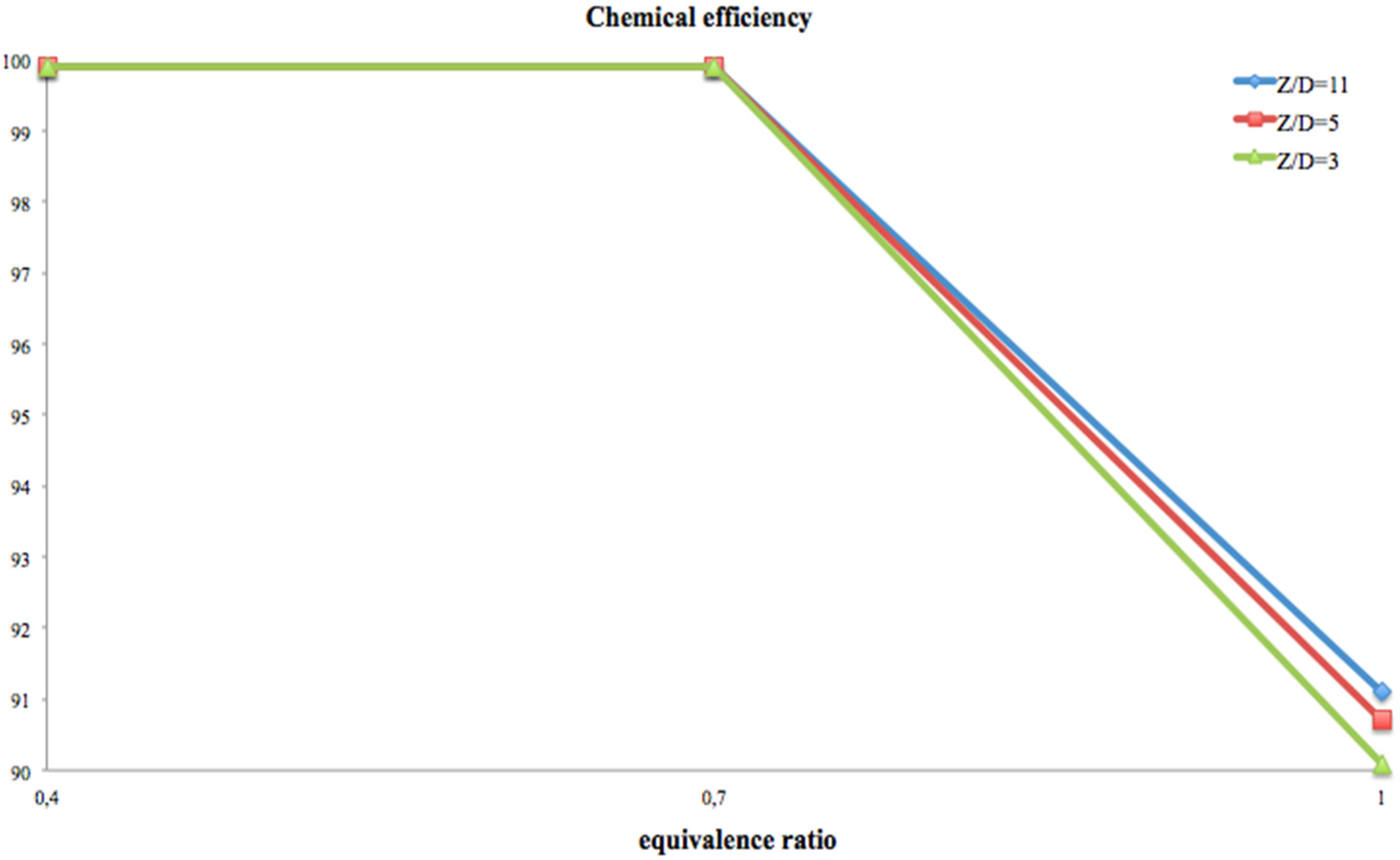
Figure 5.
Chemical efficiency.
Figure 5.
Chemical efficiency.
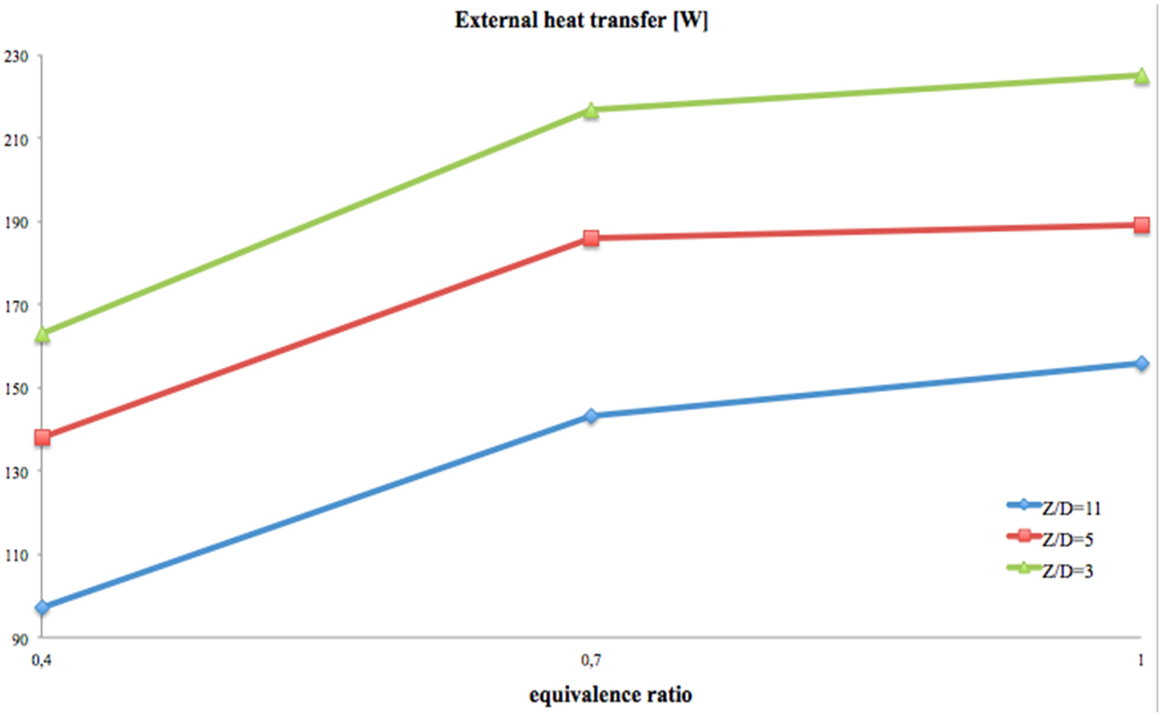
Figure 6.
External heat transfer (W).
Figure 6.
External heat transfer (W).
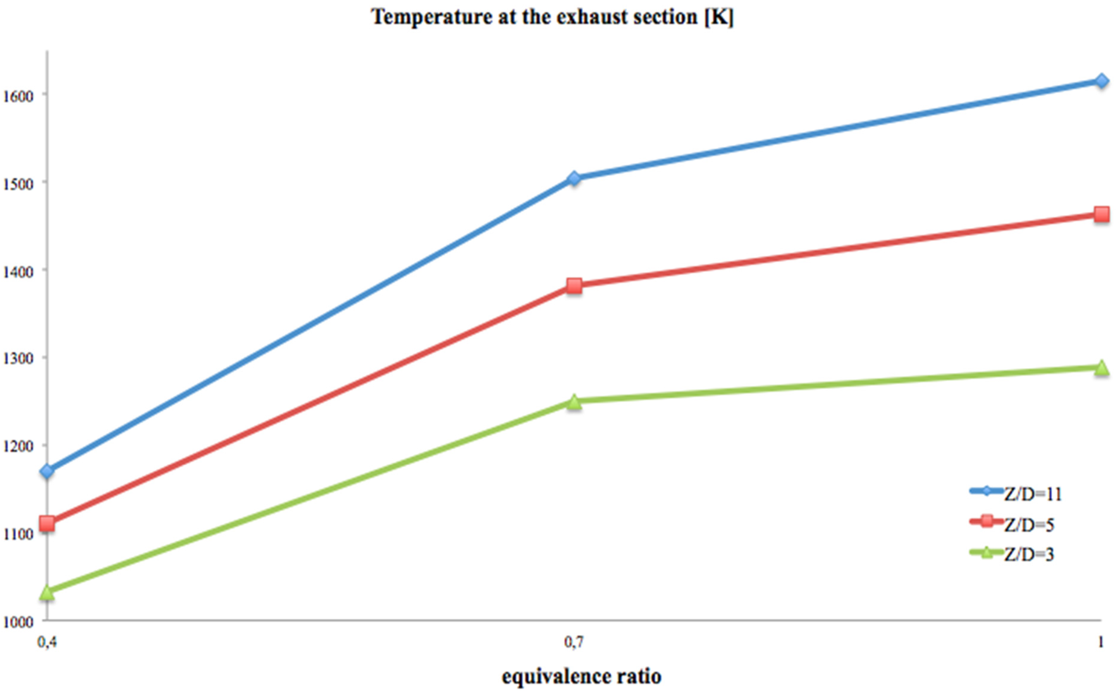
Figure 7.
Average temperature at the exhaust section (K).
Figure 7.
Average temperature at the exhaust section (K).
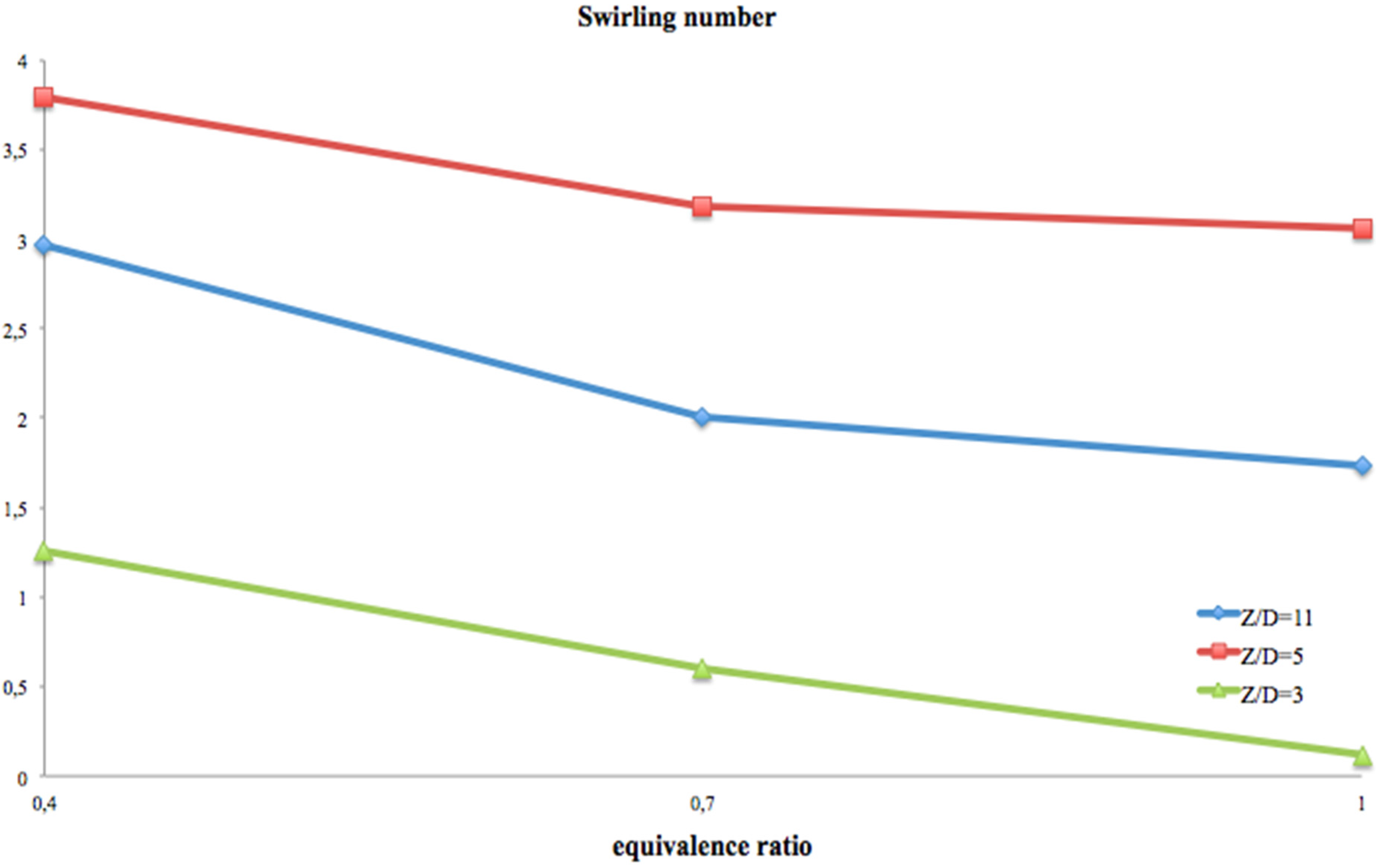
Figure 8.
Swirling number.
Figure 8.
Swirling number.
The combustion efficiency data, reported in
Table 3 and in
Figure 5, indicate that H
2 chemistry is fast enough to permit high efficiency even with the
Z/
D = 11 aspect ratio configuration (diameter equal to 3 mm). In fact, combustion is complete (chemical efficiency greater than 99%) for a wide range of equivalence ratios. It might seem singular that the lowest chemical efficiencies are at stoichiometric conditions, but this behavior can indicate that for these small dimensions, excess air is mandatory to increase the probability of efficient collisions between hydrogen and oxygen.
Figure 6 shows that the thermal power, provided to the environment, increases with the equivalence ratio. It has its highest rate passing from 0.4 to 0.7 and increases, correctly, with the inverse of the
Z/
D ratio, which is expanding the emitting surface area.
Up to about 57% of the injected thermal power is provided to the environment.
Figure 7 reports that the average temperature, at the exhaust section, grows proportionally with the
Z/
D ratio and the equivalence ratio (the highest exhaust temperatures are at stoichiometric conditions). This is a parameter of inefficiency, because it provides the indication that much energy will be wasted, and then new, more efficient geometrical configurations should be investigated (see
Section 5).
This new field of investigation is furtherly suggested by the behavior of the delta temperature data, reported in
Table 2, which show how they grow with the equivalence ratio.
As explained before, it is confirmed also by the simultaneous analysis of the average temperature, on the emitting surfaces, and its delta (see
Table 2); for an efficient energy conversion, they should be respectively greater than 1000 K and lesser or equal to 100 K. This double goal is reached for the
Z/
D = 11 configuration at
Phi = 0.4–0.7, while the other two geometrical configurations reach it only in the leanest condition. In particular, the
Z/
D = 11 configuration, at
Phi = 0.4, strictly respects both requirements, while, for all other cases, the average temperature is higher than the requirement, in some cases even much higher, but with a delta weakly greater than 100 K.
Figure 8 indicates that the swirling number,
Sw, decreases with the equivalence ratio. This behavior is probably due to two connected reasons: the first is the reduced tangential velocity (see the
Reair number,
Table 1 operating conditions), and the second is the reduced energy released inside the chamber during the combustion (see the outcomes of the temperature at the exhaust section), which affects the “pushing effect” against the cylindrical wall due to the greater specific volume of the heat products.
To delve into the main results, a deeper analysis of the Z/D = 5, Phi = 0.7 configuration is reported.
This configuration has been chosen because it might be considered a good compromise between the average temperature (the delivered power) and the brick’s dimensions (30 mm × 30 mm × 9 mm).
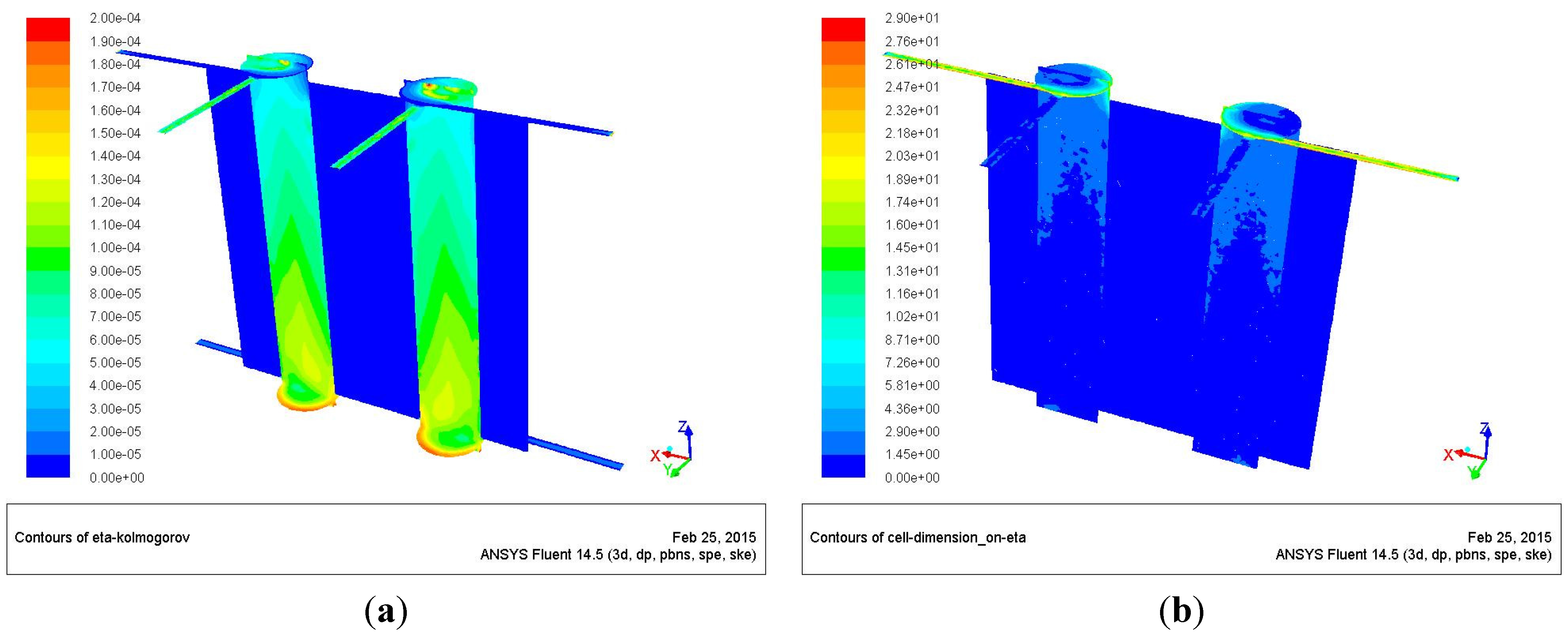
Figure 9 shows the Kolmogorov scale and its ratio with respect to the characteristic cell dimension (cubic root of the cell volume), on the
x-
z and inlet planes.
Figure 9a confirms that defining a single regime inside the chamber would be incorrect, because the Kolmogorov scale is at a maximum of two-orders of magnitude smaller than the chamber characteristic dimensions, thus identifying weak turbulence zones (in the air inlet ducts and in the first zones of the chambers) together with laminar ones (fuel inlets and inside the chambers).
The “smallest” η are in a small region close to the inlet (this region is characterized by low temperature and high velocity) and close to the wall (the region at low temperature and relative high velocity), while the largest η are in the core of the combustion chamber, where the temperature is high, and at the bottom of the chamber, where the velocity is low.
Figure 9b reports the ratio between the cell size and the Kolmogorov scales; it shows that the cell dimension is of the same order of the Kolmogorov scale throughout the chamber, while being larger at the inlet. This means that the DNS approach is feasible and that the simulation, inside the chambers, is probably close to the DNS itself.
Figure 9.
Kolmogorov scale dimension (a); cell dimension-Kolmogorov scale ratio (b).
Figure 9.
Kolmogorov scale dimension (a); cell dimension-Kolmogorov scale ratio (b).
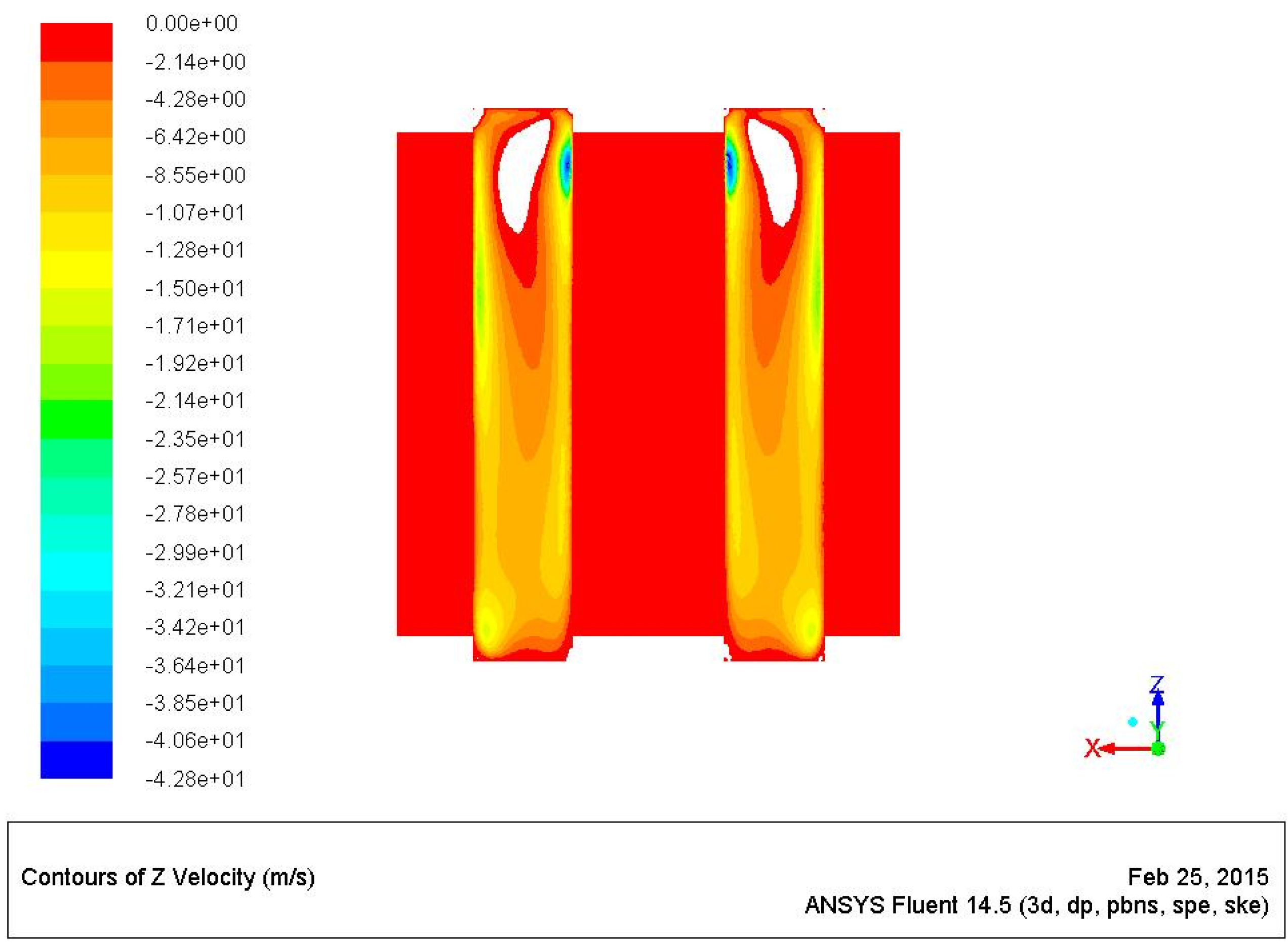
Figure 10 presents the negative
Z-velocity maps along the
XZ-plane. It shows small recirculation bubbles close to the inlet plane (the white holes in the figure are positive velocities) that are fundamental for the mixing. Good mixing improves chemical efficiency (values are reported in
Table 3).
This behavior demonstrates that the H2/air kinetics is fast enough to reach complete combustion also with small recirculation bubbles (the same is not valid for stiffer molecules, such as methane; this issue is investigated in another paper that will follow).
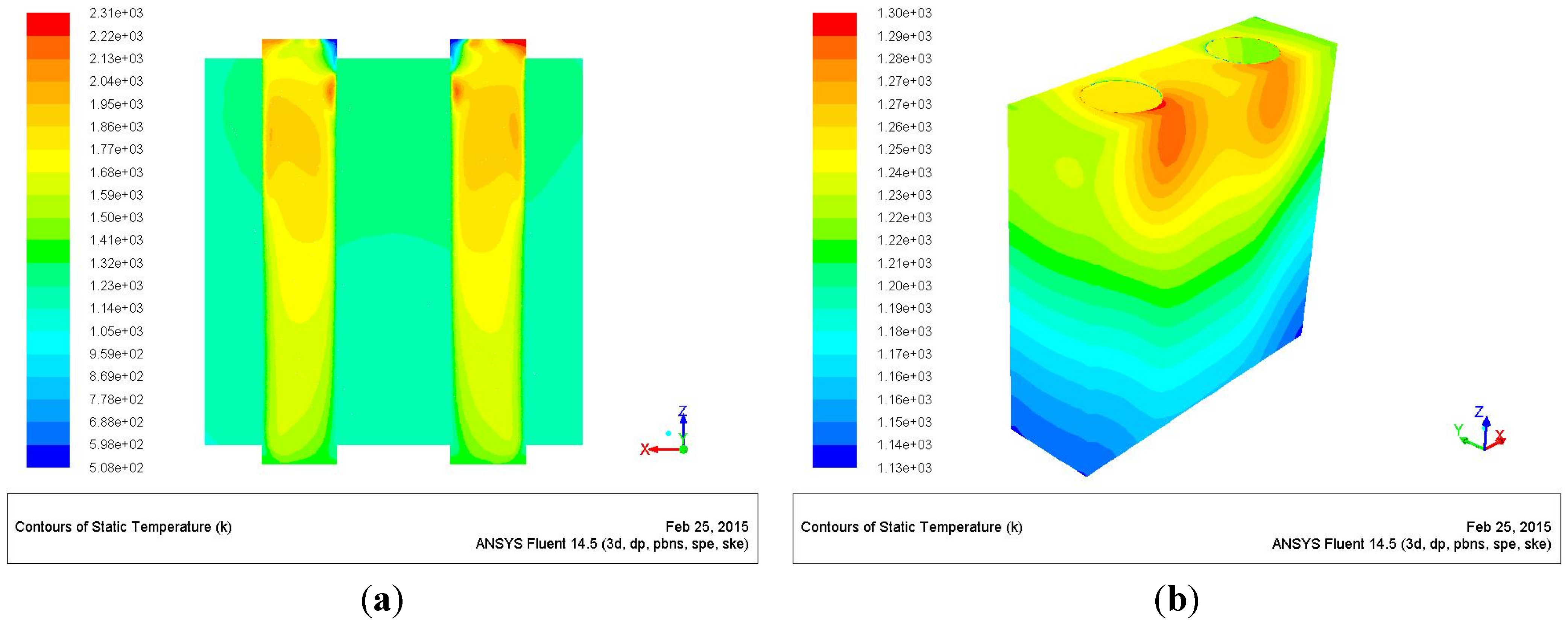
Figure 11a shows the temperature fields inside the chambers and throughout the converter, along the
XZ-plane, while
Figure 11b shows the temperature maps on the emitting surfaces.
Figure 11.
Temperature map on the XZ plane (a); temperature map on the emitting surfaces (b).
Figure 11.
Temperature map on the XZ plane (a); temperature map on the emitting surfaces (b).
The maximum temperature, inside the chambers, is predicted to be close to 2310 K.
A burning central zone, where temperature peaks, and a colder zone close to the wall are predicted. This is due to centrifugal force: as the reacting flow swirls, the centrifugal force “pushes” fresh reactants toward the wall. This forced stratification naturally protects the wall from the high gas temperature.
The external maximum temperature is 1300 K (
Figure 11b), with a delta of 165 K, while the thermal power, provided to the environment, is 186 W (
Table 2 and
Table 3).
The previous data exhort to investigate new designs, in particular for the
Z/
D = 5 configuration, which are apt at obtaining a more homogenous temperature on the emitting surfaces, leading consequently to a greater delivered power and then to a greater overall efficiency (see
Section 5).
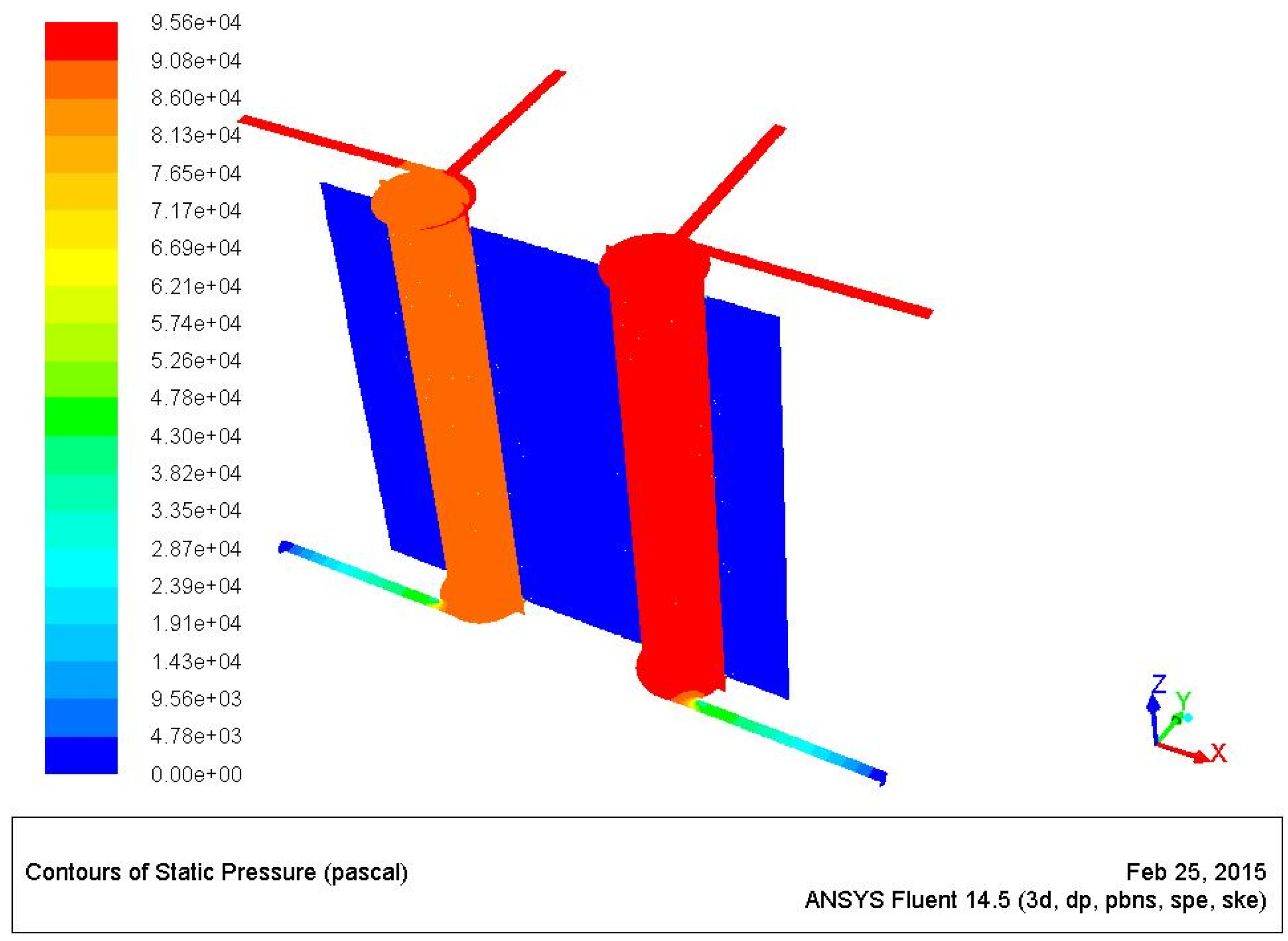
Figure 12 provides the overpressure map and shows that an overpressure of about 1 atm is necessary for this kind of device (the exhaust section is at ambient conditions,
P = 1 atm).
Figure 12.
Overpressure map on the XZ and inlet planes.
Figure 12.
Overpressure map on the XZ and inlet planes.
5. Conclusions
This work focuses on the performance of a swirling meso-combustor converter, connected to the environment, characterized by a parallelepiped block of emitting material with two separated swirling meso-chambers inside fed by H2/air.
Nine configurations, which differ for the diameter-length ratios and equivalence ratios, are reported, and the physical behavior is inspected by the comparison of relative outcomes, such as the combustion efficiency, the thermal power provided to the environment, from the emitting surfaces, the temperature at the exhaust section and the swirling number at reacting conditions.
It is possible to conclude that the H2/air kinetics is fast enough to obtain almost complete combustion even without huge recirculation bubbles; in fact, the predicted combustion efficiency is in the range 91% < η < 99.9%. Unexpectedly, the lowest value is not related to the smallest diameter dimension, but to the stoichiometric conditions, indicating that excess air is mandatory for an efficient combustion in these particular geometrical configurations.
The fluid dynamics, inside the chamber, presents laminar regime zones together with weak turbulence ones; therefore, a DNS approach will be the aim of a future study, also to confirm the results obtained with these investigations.
Even though up to about 57% of the injected thermal power is provided to the environment, further investigations apt at optimizing the energy converter device are mandatory; the high temperature values, at the exhaust sections, demonstrate that too much energy will be wasted in the case of real use.
Moreover, more homogenous temperatures, on the emitting surfaces, would lead consequently to greater delivered power to the external environment.
An energy efficiency improvement is already under investigation by means of novel geometrical configurations (connected and/or specular chambers); the approach, with the relative results, will be provided in a following paper (some of these new geometrical configurations are the object of a pending patent, as well).
Cluster configurations and/or micro-turbine connected configurations are the second aim of improved energy efficiency studies. This is suggested by the results of the temperature at the exhaust section, because it turns out that, with a few adaptations, they could match the micro-turbine blade material requirements.
Moreover, it is important to reproduce the above study, and the relative improvements, adopting hydrocarbons, such as methane and propane, and hydrocarbon-hydrogen blends, in order to understand the real suitability to everyday life necessities. Some of the hydrocarbon investigations are already in progress and will be provided as explicit results are available.


