Article

Parametric Optimization of Regenerative Organic Rankine Cycle System for Diesel Engine Based on Particle Swarm Optimization

1
College of Environmental and Energy Engineering, Beijing University of Technology, Pingleyuan No. 100, Beijing 100124, China
2
Collaborative Innovation Center of Electric Vehicles in Beijing, Pingleyuan, No. 100, Beijing 100124, China
*
Author to whom correspondence should be addressed.
Energies 2015, 8(9), 9751-9776; https://doi.org/10.3390/en8099751
Submission received: 6 August 2015 / Revised: 29 August 2015 / Accepted: 2 September 2015 / Published: 9 September 2015

Abstract

:
To efficiently recover the waste heat from a diesel engine exhaust, a regenerative organic Rankine cycle (RORC) system was employed, and butane, R124, R416A, and R134a were used as the working fluids. The resulting diesel engine-RORC combined system was defined and the relevant evaluation indexes were proposed. First, the variation tendency of the exhaust energy rate under various diesel engine operating conditions was analyzed using experimental data. The thermodynamic model of the RORC system was established based on the first and second laws of thermodynamics, and the net power output and exergy destruction rate of the RORC system were selected as the objective functions. A particle swarm optimization (PSO) algorithm was used to optimize the operating parameters of the RORC system, including evaporating pressure, intermediate pressure, and degree of superheat. The operating performances of the RORC system and diesel engine-RORC combined system were studied for the four selected working fluids under various operating conditions of the diesel engine. The results show that the operating performances of the RORC system and the combined system using butane are optimal on the basis of optimizing the operating parameters; when the engine speed is 2200 r/min and engine torque is 1215 N·m, the net power output of the RORC system using butane is 36.57 kW, and the power output increasing ratio (POIR) of the combined system using butane is 11.56%.

1. Introduction

A significant amount of petroleum resources are consumed by automobiles. Meanwhile, the effective thermal efficiency is only about one third for vehicle engines, and the waste heat is released into the atmosphere through the engine exhaust and engine coolant [1,2]. Therefore, to increase the thermal efficiency and decrease fuel consumption for vehicle engines, the recovery and utilization of waste heat from vehicle engines have recently become a research hotspot for many researchers.
The organic Rankine cycle (ORC) is an effective method for waste heat recovery, and has been widely studied and applied in many domains [3,4,5,6,7,8]. Katsanos et al. [9] conducted a theoretical study to analyze the performance of a heavy-duty truck diesel engine equipped with a Rankine bottoming cycle used for recovering waste heat from the exhaust gas. The results revealed that as engine load increases from 25% to 100%, the ORC can improve the brake specific fuel consumption (BSFC) by 10.2%–8.4% and 7.5%–6.1% when the working fluids are R245ca and water, respectively. Zhang et al. [10] designed an RORC system using R245fa and isopentane/R245fa as working fluids to recover the exhaust heat of a diesel engine, and then analyzed the influence of the intermediate pressure on running performance parameters of the RORC system. The result showed that a 10.54% improvement in power output and a 9.55% improvement in fuel economy can be achieved at the rated conditions of the diesel engine. Wei et al. [11] performed a three-dimensional transient computational fluid dynamic numerical investigation based on dynamic mesh technology to study the unsteady flow in the suction process of a scroll expander used for the ORC system. The result showed that the mass flow rate, gas driving moment, and pressure in the working chambers are key factors affecting transient performances of the scroll expander. Xie and Yang [12] established a Rankine cycle system and discussed its operating performances under an actual driving cycle. The results indicated that the on-road Rankine cycle system efficiency is as low as 3.63%, which is less than half of the designed Rankine cycle system efficiency (7.77%) at the rated operating point.
For the ORC waste heat recovery systems, the match of working fluids with systems and heat source heavily affects the system performance [13,14]. Roy and Misra [15] presented an analysis of the regenerative organic Rankine cycle (RORC) based on parametric optimization using R123 and R134a during superheating at a constant pressure of 2.50 MPa under realistic conditions. The result showed that R123 has been found to be a better working fluid than R134a for converting low grade heat to power. Wang et al. [16] assessed nine different working fluids according to their physical and chemical properties for the ORC system of a vehicle diesel engine and studied their respective performances. R11, R141b, R113, and R123 manifest slightly higher thermodynamic performance than the others; however, R245fa and R245ca are the most environmental-friendly working fluids for engine waste heat recovery applications. Van et al. [17] compared the thermodynamic performance of the supercritical ORC system using different working fluids by ranking method and exergy analysis method. The result showed that the best working fluids for system efficiency optimization of basic and regenerative cycles are R32 and R152a, respectively; the best working fluid for net electrical power optimization of basic cycle is R1234ze. Although CO2 has many desirable environmental and safety properties, the worst thermodynamic performance is always found with the cycle using this compound as working fluid. Aghahosseini and Dincer [18] conducted a comprehensive thermodynamic analysis of the ORC, and the cycle performance was analyzed and compared for different pure and zeotropic-mixture working fluids. The environmental characteristics of the working fluids, such as toxicity, flammability, ozone depletion potential (ODP) and global warming potential (GWP) were studied; and the cycle CO2 emission was compared with different fuel combustion systems. Results showed that R123, R245fa, R600a, R134a, R407c, and R404a can be considered as potential working fluids.
Generally, the traditional optimization methods do not consider the mutual influence of the operating parameters of the ORC system. Moreover, researchers have proposed some optimization algorithms for parameter optimization of ORC systems [19,20]. Feng et al. [21] compared the exergy efficiency and the heat exchanger area per unit net power output between the basic ORC and RORC using a non-dominated sorting genetic algorithm-II. The results indicated that the optimum exergy efficiency and the heat exchanger area per unit net power output of the RORC were obtained from the Pareto-optimal solution are 59.93% and 3.07 m2/kW, which are 8.10% higher and 15.89% lower than that of the basic ORC, respectively. Xiao et al. [22] conducted an optimization of the evaporation temperature and condensation temperature of subcritical ORC by using the pure working fluids R600a, R245fa, R601a, R601, R123, and non-azeotropic mixed working fluids, including R600a/R601a, R245fa/R601a, R245fa/R601, R600a/R245fa. Their analysis indicated that the multi-objective optimization of ORC shows superiority to the single-objective optimization, and the ORC performance of mixed working fluids is not always better than that of pure working fluids.
Recently, most research on ORC waste heat recovery system has mainly involved a discussion on the thermodynamic performance of different ORC systems and working fluids. However, few researches have investigated the thermodynamic performance of the ORC system using novel optimization algorithm [23,24,25]. In this research, the variation tendency of engine exhaust energy rate under various operating conditions was obtained by experiment; a RORC system was employed to recover the exhaust heat from the diesel engine by using four different working fluids. Based on the particle swarm optimization (PSO) algorithm, the operating parameters of the RORC system were optimized to obtain the optimal net power output and exergy destruction rate of the RORC system. The operating performances of the RORC system and diesel engine-RORC combined system were analyzed for four different working fluids under various operating conditions of the diesel engine.
Many electrical devices are powered by the electricity generator and battery in the vehicle. In this research, an RORC system is introduced to recover waste heat from diesel engine exhaust, and the expander is used to drive the electricity generator. Consequently, the fuel economy of the vehicle engine can be improved effectively. Furthermore, electricity generation by recovering waste heat of vehicle engines may also potentially save energy and reduce emissions. In turn, this may be considered an efficient method for the internal combustion engine-electric motor hybrid vehicles in the near future.

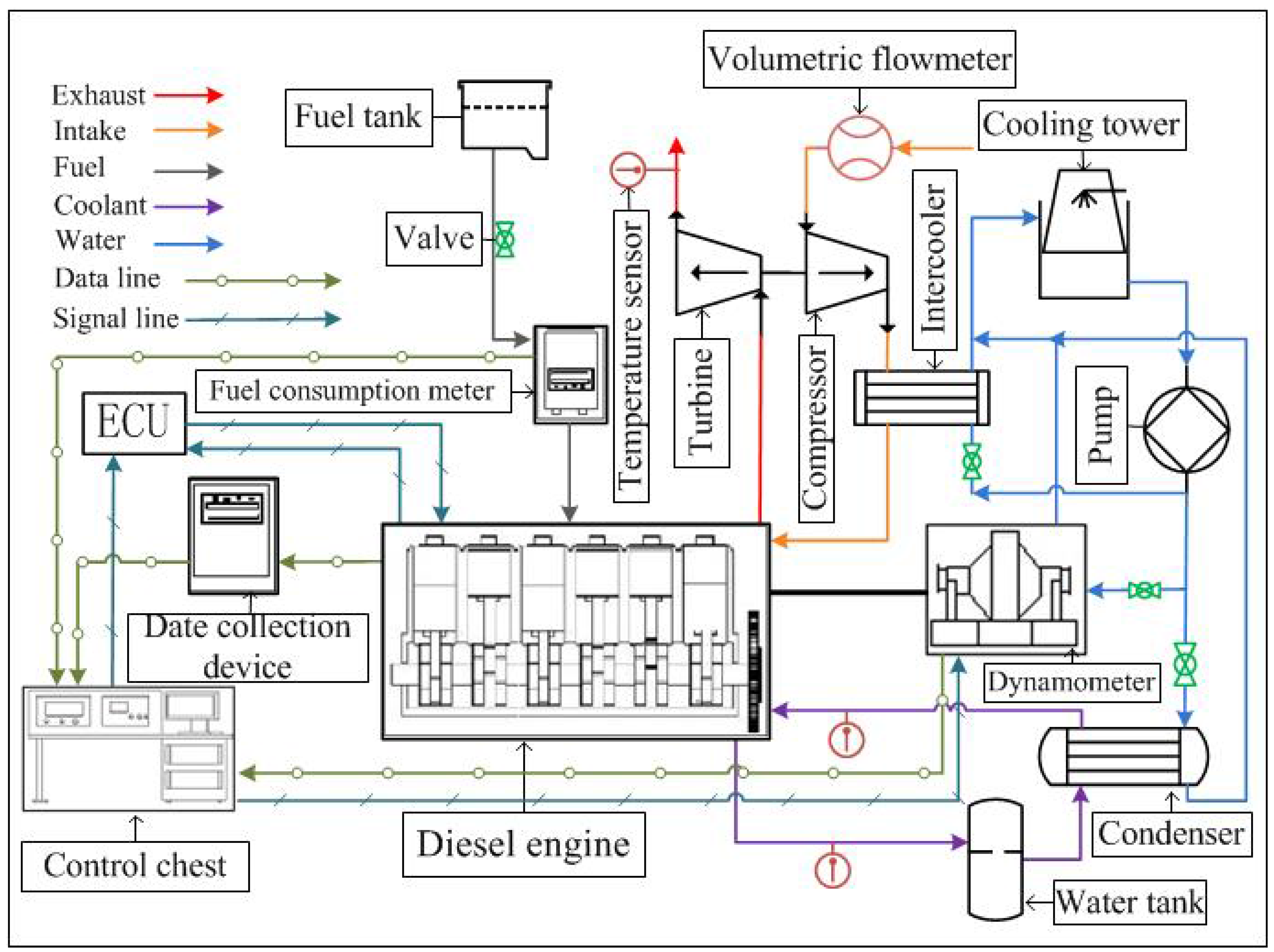
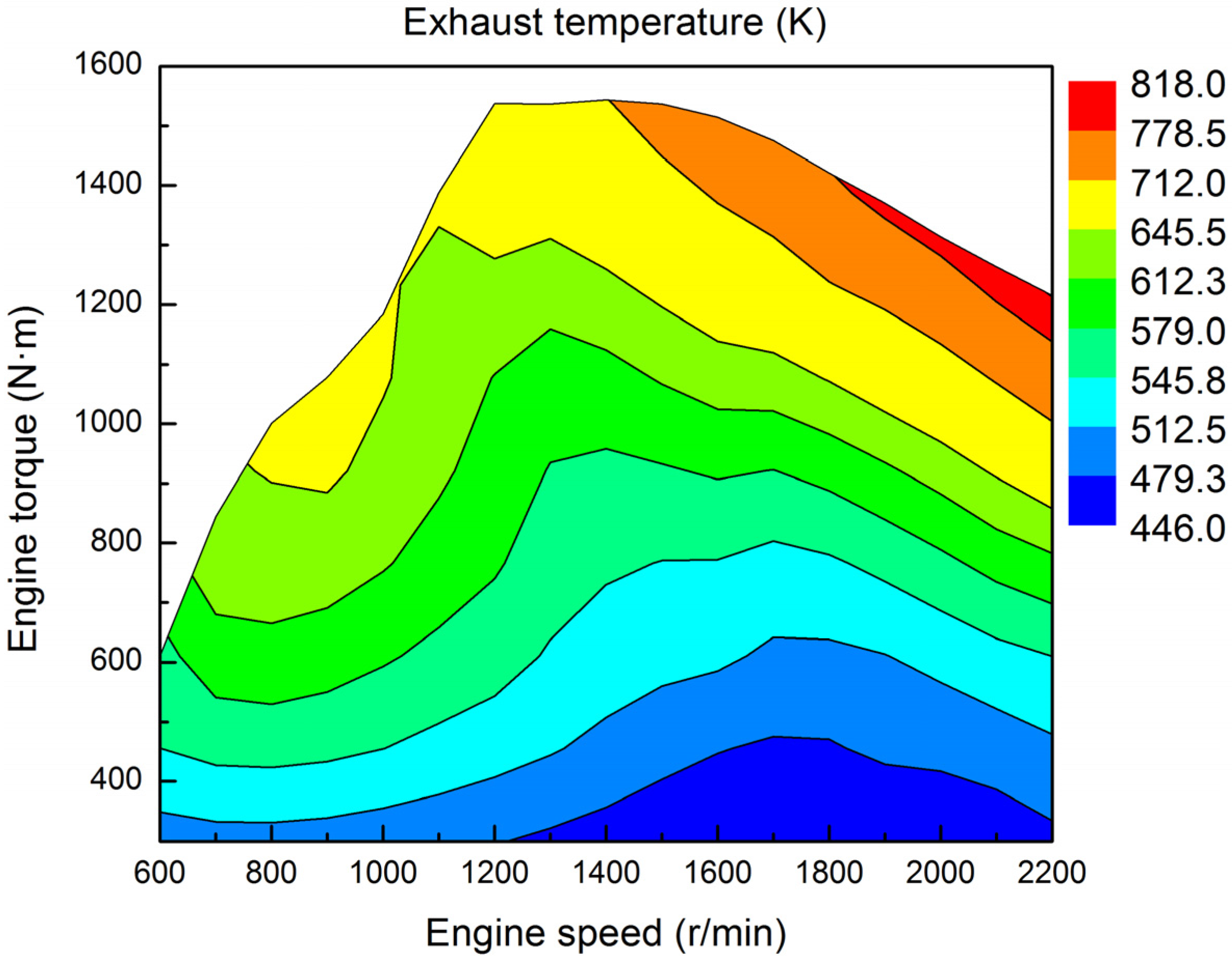
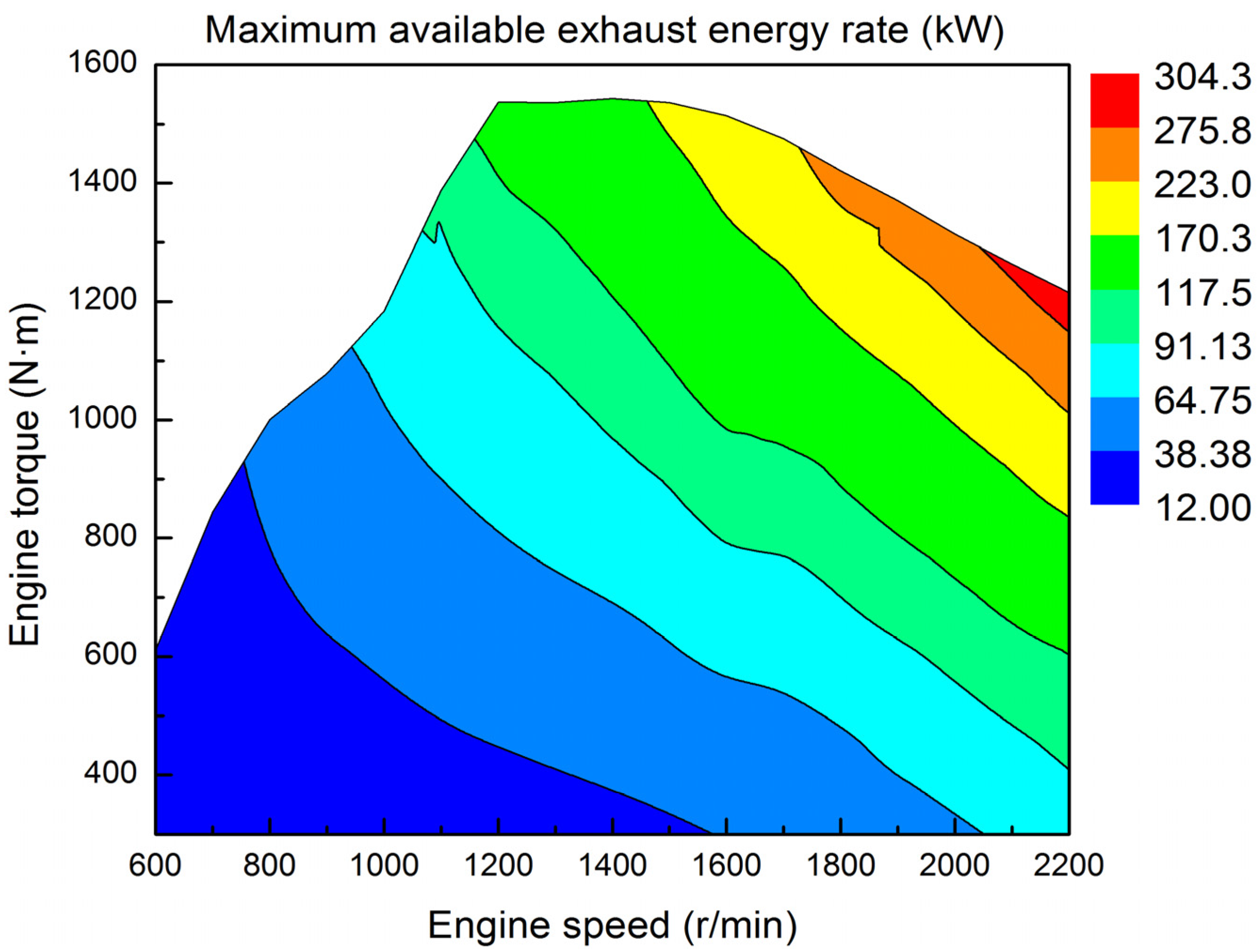
2. Exhaust Energy of the Vehicle Diesel Engine

In practice, a vehicle diesel engine generally runs under various operating conditions, and the exhaust energy from the diesel engine varies with the engine operating conditions. To recover the engine exhaust energy efficiently, the variation tendency of engine exhaust energy rate should be captured under various operating conditions of the diesel engine.
In this research, the diesel engine used for the study of waste heat recovery is a six-cylinder and four-stroke vehicle diesel engine. The main parameters of the vehicle diesel engine are listed in Table 1. The diesel engine experimental system is illustrated in Figure 1. Testing the engine was conducted under more than 85 operating conditions. During the diesel engine tests, the engine speed varied from 600 r/min to 2200 r/min, and the engine torque varied from 300 N·m to 1500 N·m.
Table 1. Main parameters of the diesel engine.
ItemsParametersUnits
Displacement9.726L
Rated power280kW
Maximum torque1500N·m
Rated speed2200r/min
Stroke130mm
Cylinder diameter126mm
Compression ratio17-
Figure 1. Schematic diagram of the experimental diesel engine system.
Energies 08 09751 g001
Power output of the diesel engine under various operating conditions is shown in Figure 2, where the power output of the diesel engine gradually increases with the increase of engine torque and engine speed; the maximum is 279.9 kW.
Figure 2. Power output of the diesel engine.
Energies 08 09751 g002
The BSFC of the diesel engine under various operating conditions is shown in Figure 3. As can be seen, the BSFC is relatively low in the medium and high load regions of the engine. When the engine speed is 1200 r/min and the engine torque is 1131 N·m, BSFC reaches a minimum value of 185 g/kW·h.
Figure 3. Brake specific fuel consumption (BSFC) of the diesel engine.
Energies 08 09751 g003
Exhaust temperature of the diesel engine under various operating conditions is shown in Figure 4. As shown in the figure, engine exhaust temperature increases with engine torque; the maximum is about 818 K.
Figure 4. Exhaust gas temperature of the diesel engine.
Energies 08 09751 g004
The equation below is used to compute the maximum available exhaust energy rate:
Q ˙ exh = c p , exh m ˙ exh ( T exh T 0 )
Therein, c p , exh is the exhaust specific heat at constant pressure, which can be calculated as follows [26]:
c p , exh = 0.00025 T exh + 0.99
The maximum available exhaust energy rate under various operating conditions can be obtained on the basis of engine test data and the calculation results for the exhaust energy rate. As shown in Figure 5, the variation tendency of the maximum available exhaust energy rate is similar to that of the engine power output; the peak value of the maximum available exhaust energy rate is 304.3 kW.
Figure 5. Maximum available exhaust energy rate of the diesel engine.
Energies 08 09751 g005

3. Regenerative Organic Rankine Cycle (RORC) System

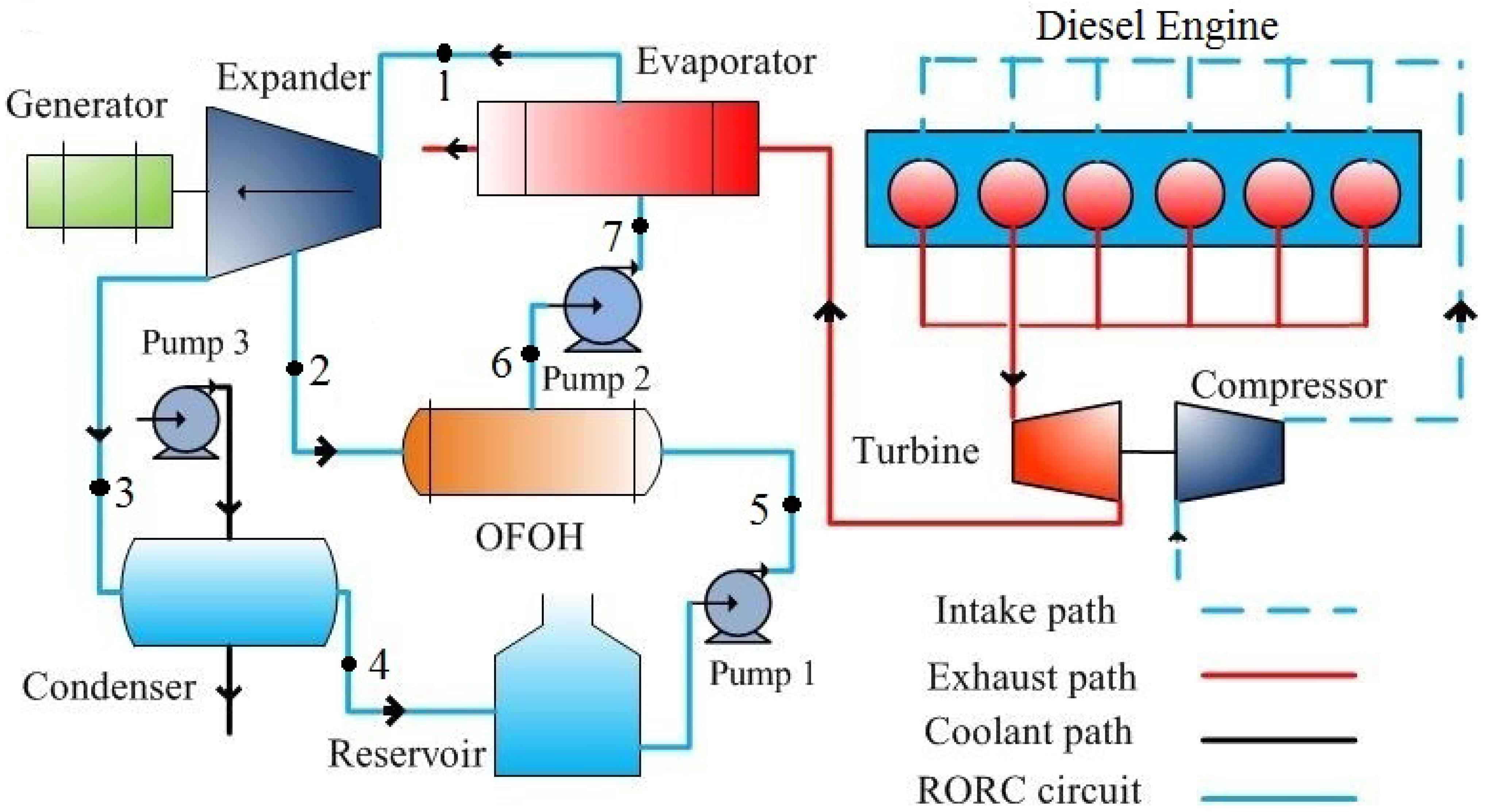
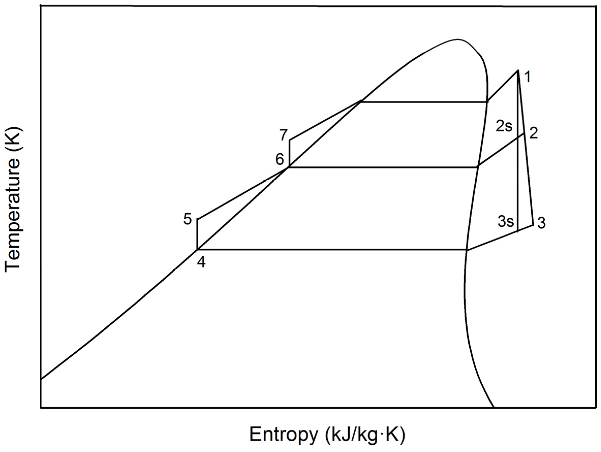
3.1. Description of the Regenerative Organic Rankine Cycle (RORC) System

In this research, a set of devices for regeneration was added to an ORC system to implement a RORC system. The working principle of the RORC system is similar to that of the regenerative steam Rankine cycle system in power plants, the main difference between them being the working fluids used. Consequently, an open feed organic fluid heater (OFOH) is used for the RORC system just as an open feedwater heater is used for the regenerative steam Rankine cycle system in power plants. The crucial components of the RORC system consist of an evaporator, an expander, a generator, a condenser, a reservoir, three pumps, and an OFOH. The schematic diagram of the RORC system is shown in Figure 6. The RORC system operates according to a process explained here. First, the saturated liquid state working fluid is pressurized into a subcooled liquid state by Pump 2, and then the working fluid enters the evaporator. The working fluid absorbs the heat from the engine exhaust and turns into vapor with high temperature and high pressure in the evaporator. The vapor then flows into the expander to produce useful work. When the vapor pressure decreases to an intermediate pressure (the pressures at which the vapor is extracted from the expander), part of the vapor is extracted and sent into the OFOH for regeneration, whereas the rest of the vapor continues to expand to produce more work until the pressure drops to the condensing pressure. Then, the vapor with low temperature and low pressure enters the condenser, where it turns into a saturated liquid state by cooling water and flows into the reservoir. Pump 1 then pressurizes the liquid from the reservoir and sends it into the OFOH to exchange heat and mix with the vapor extracted from the expander. Finally, the working fluid in a saturated liquid state is pressurized by Pump 2 to the evaporating pressure and sent into the evaporator; thus, the RORC system completes one working cycle.
Figure 6. Schematic diagram of the regenerative organic Rankine cycle (RORC) system.
Energies 08 09751 g006

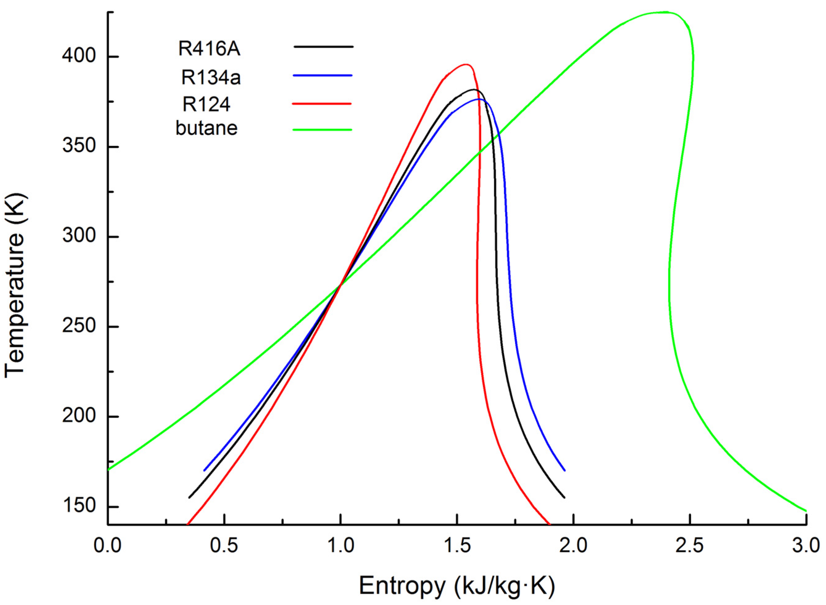
3.2. Organic Working Fluid Selection

Organic working fluid selection is crucial to the performance of an RORC system. On the one hand, the safety level and environmental impact of the working fluid should be considered important to the application of the RORC system. On the other hand, the selected working fluid should make the RORC system more efficient and stable [27]. In this research, based on a comprehensive consideration of the above-mentioned factors, the zeotropic mixture R416A and the pure working fluids butane, R124, R134a were selected for the RORC system. The thermodynamic properties of the working fluids can be calculated by using the software REFPROP developed by the National Institute of Standards and Technology in the United States. Table 2 lists the main properties of the four selected working fluids. Figure 7 is the T-s diagram for the four selected working fluids.
Table 2. Main properties of the four working fluids. GWP: global warming potential; ODP: ozone depletion potential.
Working fluidsComponentsComposition (mass fraction)Tcri (K)Pcri (MPa)Safety groupGWP (100 Years)ODP
butane--425.133.796A3200.000
R124--395.433.624A16200.026
R134a--374.214.059A113700.000
R416AR124/R134a/butane0.395:0.59:0.015380.233.975A1/A110000.010
Safety group: A: lower toxicity; B: higher toxicity; 1: no flammability; 2: lower flammability; 3: higher flammability.
Figure 7. T-s diagram for the four working fluids.
Energies 08 09751 g007

3.3. Thermodynamic Modeling of the Regenerative Organic Rankine Cycle (RORC) System

The thermodynamic model of the RORC system was established based on the first and second laws of thermodynamics. The T-s diagram of the RORC system is shown in Figure 8.
The restricted conditions for the thermodynamic calculations are listed as follows:
(1)
The pressure drop and heat loss in the tubes are neglected;
(2)
The evaporating pressure varies from 1.5 MPa to 2.5 MPa;
(3)
The intermediate pressure varies from 0.9 MPa to 1.8 MPa;
(4)
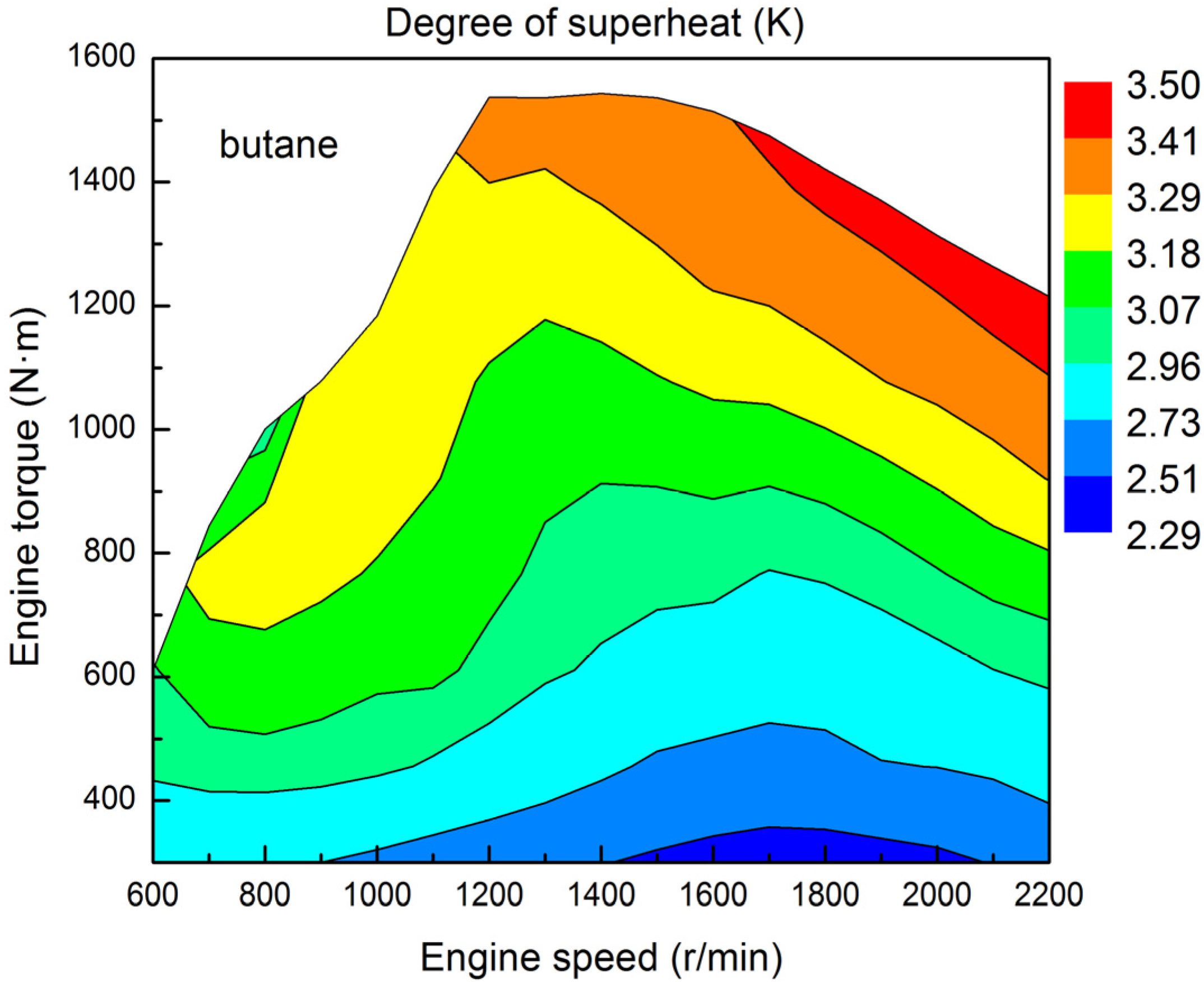
The degree of superheat varies from 0 K to 10 K;
(5)
The isentropic efficiency of the expander is set to 0.85;
(6)
The heat exchange coefficient of the evaporator is set to 0.85, which is the ratio of the heat absorbed by the organic working fluids in the evaporator to the heat released by engine exhaust when passing through the evaporator;
(7)
The ambient temperature and condensing temperature are set to 288 K and 303 K, respectively;
(8)
The exhaust temperature at the outlet of the evaporator (Tout) is set to 380 K [28].
Figure 8. T-s diagram of the RORC system.
Energies 08 09751 g008
The saturation temperatures for the four working fluids at the relevant evaporating and intermediate pressures are listed in Table 3.
Table 3. The saturation temperatures for the four working fluids at the relevant evaporating and intermediate pressures.
Working fluidsTsa (K), 1.5 MPaTsa (K), 2.5 MPaTsa (K), 0.9 MPaTsa (K), 1.8 MPa
R416ADew point334.83357.78314.53342.72
Bubble point333.21356.47312.77341.17
Butane372.27400.11347.84381.81
R134a328.38350.73308.68336.05
R124350.87375.70328.99359.38
In the OFOH, vapor extracted from the expander is mixed with the liquid working fluid after condensation. The fraction of vapor extracted is calculated by using the following equation:
α = h 6 h 5 h 2 h 5
Process 1–3 is the actual expansion process of the working fluid in the expander. The isentropic efficiency of the expander is computed as follows:
η t = h 1 h 3 h 1 h 3s
The power output of the expander is calculated as follows:
W ˙ t = m ˙ o [ ( h 1 h 2 ) + ( 1 α ) ( h 2 h 3 ) ]
Process 4–5 and Process 6–7 are the compression processes of the working fluid, the power consumed by Pump 1 and Pump 2 are respectively calculated using the equations given by:
W ˙ p 1 = m ˙ o ( 1 α ) ( h 5 h 4 )
W ˙ p 2 = m ˙ o ( h 7 h 6 )
Process 3–4 is the condensation process of condenser, the heat exchange rate of the condenser is: expressed as:
Q ˙ con = m ˙ o ( 1 α ) ( h 3 h 4 )
The power consumed by Pump 3 is [29]:
W ˙ p 3 = m ˙ w g H
Process 7–1 is the evaporation process of the working fluid at constant pressure in the evaporator, the heat exchange rate of the evaporator is calculated as follows:
Q e = m ˙ o ( h 1 h 7 ) = c p , exh m ˙ exh ( T exh T out ) η e
The net power output of the RORC system is calculated by:
W ˙ net = W ˙ t W ˙ p 1 W ˙ p 2 W ˙ p 3
The exergy destruction rate of the RORC system is calculated as follows:
I ˙ = T 0 m ˙ o [ ( h 7 h 1 ) T H ( 1 α ) ( h 4 h 3 ) T L ]
where TH is the temperature of the high-temperature heat source, TL is the temperature of the low-temperature heat source:
T H = T exh + T out 2
where the arithmetic mean temperature of the exhaust inlet and outlet temperatures in the evaporator is taken as the temperature of the high-temperature heat source TH:
T L = T w1 + T w2 2
where the arithmetic mean temperature of the cooling water inlet and outlet temperatures in the condenser is taken as the temperature of the low-temperature heat source TL [22].
The waste heat recovery efficiency (WHRE) is defined as the ratio of the net power output of the RORC system to the maximum available exhaust energy rate of the diesel engine, which can be calculated using the following equation:
W H R E = W ˙ net Q ˙ exh × 100 %

4. Parametric Optimization of the Regenerative Organic Rankine Cycle (RORC) System

4.1. Particle Swarm Optimization (PSO)

In this research, the net power output and exergy destruction rate of the RORC system were selected as the objective functions, and the PSO algorithm was used to optimize three operating parameters of the RORC system: evaporating pressure, intermediate pressure, and degree of superheat.
PSO is a popular, simple, and stochastic global optimizer first introduced by Kennedy and Eberhart in 1995. PSO imitates the social behaviors of animals such as bird flocks in searching for optimal solutions. A potential solution is defined as a moving point called “particle” with a position vector and velocity vector, and its search behavior for updating the movement track is similar to “flying” in the search space [30]. Figure 9 shows the flow chart of the PSO.
Figure 9. Flow chart of the particle swarm optimization (PSO).
Energies 08 09751 g009
Some particles (population size, K) exist in a swarm, the particles “fly” in a D-dimensional search space (D is equal to the number of variables, D is 3 in this study) by updating the position x i n = ( x i 1 n , x i 2 n ,··· x i j n ,···, x i D n ) and the velocity v i n = ( v i 1 n , v i 2 n ,···, v i j n ,···, v i D n ), where, i = 1, 2,···, K; j = 1, 2, …, D. The position and velocity of the particles can be expressed by using Equations (16) and (17), respectively. The corresponding equations are given by:
ν i j n + 1 = ω × ν i j n + c 1 × r a n d 1 × ( p b e s t i j n x i j n ) + c 2 × r a n d 2 × ( g b e s t j n x i j n )
x i j n + 1 = x i j n + ν i j n + 1
Therein, c1 and c2 are acceleration coefficients, both of them are set to 2. Both rand1 and rand2 are therandom numbers (between 0 and 1) with uniform distribution for every dimension j of particle x i n . In addition, ω is called inertia weight, which plays the role of balancing between the global search ability and local search ability. In this study, ω is calculated using [31]:
ω ( n ) = ω min + ω max ω min N max × ( N max n )
where N max is the maximum iteration number, n is the current iteration (or generation), and ω min is the minimum inertia weight set to 0.4, ω max is the maximum inertia weight set to 0.9.
The “personal best position” p b e s t i n = ( p b e s t i 1 n , p b e s t i 2 n ,···, p b e s t i j n ,···, p b e s t i D n ) is the best position for an individual particle at the current generation, and the “global best position” g b e s t n = ( g b e s t 1 n , g b e s t 2 n ,···, g b e s t j n ,···, g b e s t D n ) is the best position for all the particles at the current generation. These values are continuously updated during the optimization process. Consequently, the global optimum can be achieved at the end of the PSO.
The initial position of an individual particle x i 0 = ( x i 1 0 , x i 2 0 ,···, x i j 0 ,···, x i D 0 ) is randomly generated in the search space, and the initial velocity of an individual particle v i 0 = ( v i 1 0 , v i 2 0 ,···, v i j 0 ,···, v i D 0 ) is set as a zero vector. All the particles (potential solutions) must be evaluated by minimizing a fitness function at every generation (or iteration). In this research, the fitness function was defined as the ratio of RORC exergy destruction rate to RORC net power output.
For all the particles, the global best position corresponds to the minimum fitness value at every generation (or iteration). To obtain the proper population size and maximum iteration number, we selected the minimum fitness function value to evaluate the influences of the population size and the iterations on the PSO. For the RORC system using R134a, when the maximum iteration number is 600, the population sizes are 10, 20, 30, 40 and 50. The variation of minimum fitness function value with the iterations and population size is shown in Figure 10. Considering the initial position of an individual particle is randomly generated in the search space, for the same population size, optimization calculations were conducted five times to ensure the solution quality. As shown in Figure 10, when the population sizes are 10 and 20, the minimum fitness function value cannot converge to the same value for the five selected initial positions of an individual particle; when the population sizes are 30, 40 and 50, the minimum fitness function value can converge to the same value for the five selected initial positions of an individual particle. Moreover, when the population sizes are 30 and 40, the maximum iteration number should be over 410, and when the population size is 50, the maximum iteration number should be over 300. Therefore, for the population sizes of 30, 40 and 50, when the maximum iteration number is over 410, the minimum fitness function value can converge to the same value for the five selected initial positions of an individual particle. In this research, population size was set to 40, and maximum iteration number was set to 500.
Figure 10. Variation of minimum fitness function value with the iterations and population size.
Energies 08 09751 g010

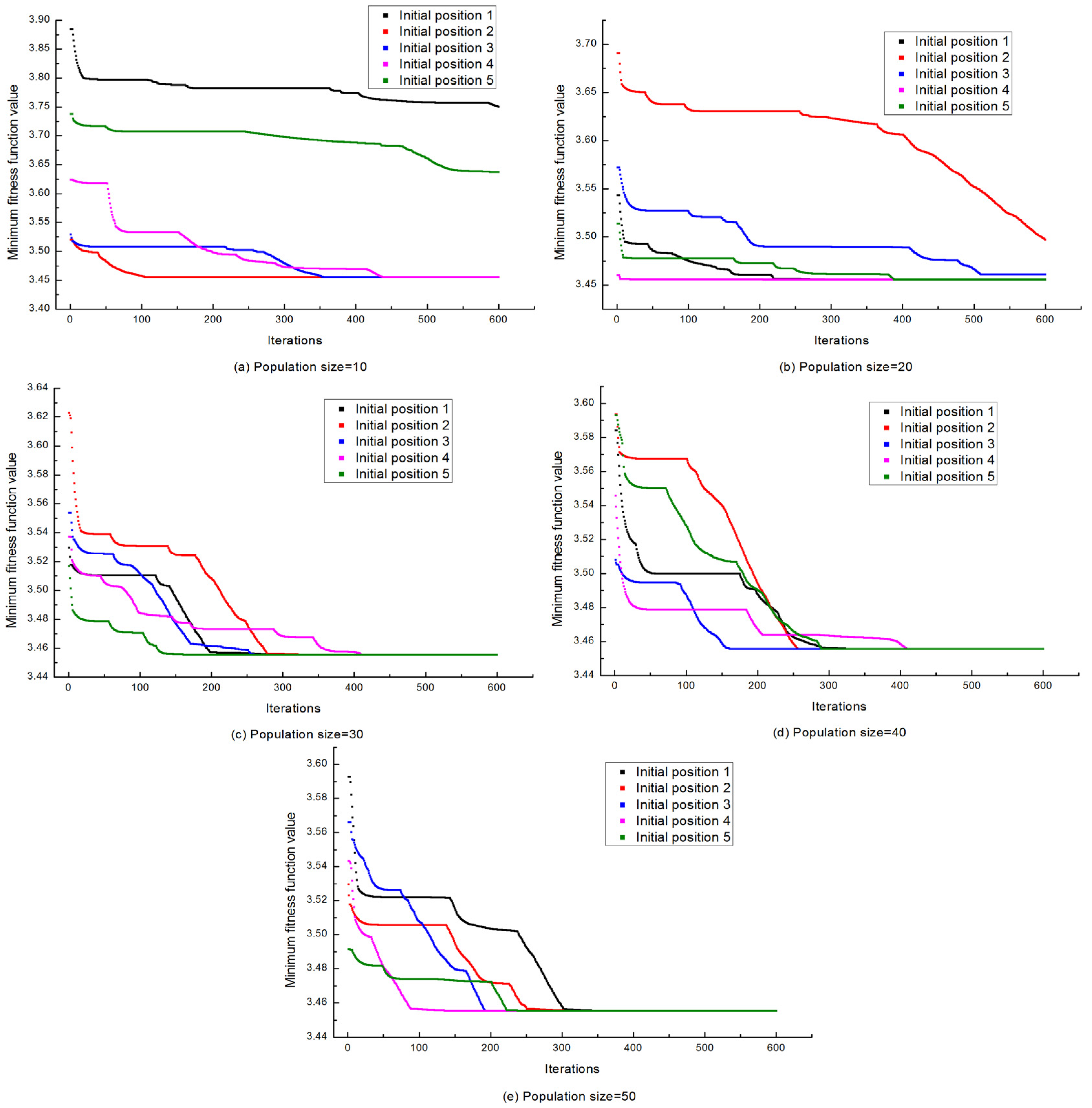
4.2. Results and Analysis of Parametric Optimization

For the four selected working fluids, the operating parameters of the RORC system were optimized by using the PSO algorithm under various operating conditions of the vehicle diesel engine.
Intermediate pressure (the pressure at which the vapor is extracted from the expander) influences the thermodynamic performance of the RORC system. The variation of the optimized intermediate pressure with engine operating conditions is shown in Figure 11. As seen in the figure, the amplitude of the optimized intermediate pressure variation is below 7 kPa for each working fluid under various operating conditions of the diesel engine. When the engine speed and engine torque are unchanged, namely under the same operating condition of the diesel engine, the order of the optimized intermediate pressure for the four selected working fluids decreasing in sequence is as follows: R134a > R416A > R124 > butane.
Figure 11. Variation of the optimized intermediate pressure: (a) butane; (b) R124; (c) R134a; and (d) R416A.
Energies 08 09751 g011
For butane, the variation of the optimized degree of superheat with engine operating conditions is shown in Figure 12. As seen in the figure, the optimized degree of superheat increases with the increase of engine torque, the optimized degree of superheat ranges from 2.29 K to 3.50 K under various operating conditions of the diesel engine, and the amplitude of the optimized degree of superheat variation is below 2 K.
Through calculations using the PSO algorithm, we find that the optimized evaporating pressures are all 2.5 MPa (maximum value available for calculation in this research) for the four selected working fluids under various operating conditions of the diesel engine. Furthermore, the optimized degrees of superheat are all 10 K (maximum value available for calculation in this research) for the working fluids R134a, R416A, and R124 under various operating conditions of the diesel engine.
Figure 12. Variation of the optimized degree of superheat.
Energies 08 09751 g012
Through calculation using the PSO algorithm, the variation of the net power output of the RORC system with engine operating conditions is shown in Figure 13.
Figure 13. Variation of the net power output of the RORC system: (a) butane; (b) R124; (c) R134a; and (d) R416A.
Energies 08 09751 g013
It can be seen that, for the four selected working fluids, the net power outputs of the RORC system all increase with the increase of the engine speed and engine torque. The main reason for this is, with the increase of engine speed and engine torque, the maximum available exhaust energy rate of the diesel engine increases, then more working fluid can be heated, evaporated, and superheated. When the engine speed and engine torque are unchanged, namely under the same operating condition of the diesel engine, the order of the net power outputs of the RORC system for the four selected working fluids decreasing in sequence is as follows: butane > R124 > R416A > R134a. For the four selected working fluids, the net power output of the RORC system ranges from 0.60 kW to 36.57 kW. When the engine speed is 2200 r/min and engine torque is 1215 N·m, the net power output of the RORC system using butane is the maximum (36.57 kW), whereas that using R134a is the minimum (21.28 kW) among the four selected working fluids.
There are many electrical devices in the vehicle, and the electrical devices are powered by the vehicle engine, electricity generator and battery; generally, the electricity generator is driven by the shaft work (namely crankshaft) of the vehicle engine, which certainly decreases the net power output of the vehicle engine. In this research, a RORC system is presented to recover waste heat from a diesel engine, and the expander is connected with the generator to produce electricity, then the electrical devices can be powered by RORC system, electricity generator and battery; consequently, we do not need to connect the electricity generator with the shaft work (namely crankshaft) of the vehicle engine. Furthermore, electricity generation based on waste heat recovery of vehicle engine may also be an efficient way of improving fuel economy for the internal combustion engine-electric motor hybrid vehicle in the near future.
Using the PSO algorithm, the variation of the exergy destruction rate of the RORC system with engine operating conditions is shown in Figure 14. It can be seen that, for the four selected working fluids, the exergy destruction rates of the RORC system all increase with the increase of the engine speed and engine torque. The main reason for this is, with the increase of engine speed and engine torque, engine exhaust temperature increases, then, the temperature difference of heat transfer between the engine exhaust and the working fluid also increases.
Figure 14. Variation of the exergy destruction rate of the RORC system: (a) butane; (b) R124; (c) R134a; and (d) R416A.
Energies 08 09751 g014aEnergies 08 09751 g014b
When the engine speed and engine torque are unchanged, namely under the same operating condition of the diesel engine, the order of the exergy destruction rates of the RORC system for the four selected working fluids increasing in sequence is as follows: butane < R124 < R416A < R134a. The average exergy destruction rate can be computed, while considering more than 85 operating condition points of the diesel engine. The average exergy destruction rates for butane, R124, R416A, and R134a are 13.68 kW, 15.86 kW, 17.71 kW and 18.19 kW, respectively.

5. Performance Analysis of the Regenerative Organic Rankine Cycle (RORC) System and Diesel Engine-RORC Combined System

To obtain a comprehensive evaluation of the improvement in power output and fuel economy, the concept of “diesel engine-RORC combined system” is presented. In the combined system (short for the diesel engine-RORC combined system), the diesel cycle (for the vehicle diesel engine) is the topping cycle, and the Rankine cycle (for the RORC system) is the bottoming cycle. The operating performances of the RORC system and diesel engine-RORC combined system were analyzed on the basis of parametric optimization.
The variation of the WHRE of the RORC system with engine operating conditions is shown in Figure 15. As shown in the figure, the WHRE of the RORC system increases with the increase of engine torque. Compared with that shown in Figure 4, the variation tendency of the WHRE of the RORC system is similar to that of the engine exhaust temperature. When the engine exhaust temperature is high, the WHRE of the RORC system is high, and vice versa. When the engine speed and engine torque are unchanged, namely under the same operating condition of the diesel engine, the order of the WHRE of the RORC system for the four selected working fluids decreasing in sequence is as follows: butane > R124 > R416A > R134a. When the engine speed is 2200 r/min and engine torque is 1215 N·m, the WHRE of the RORC system using butane is the maximum (12.02%), whereas that using R134a is the minimum (6.99%) among the four selected working fluids.
Figure 15. Variation of the WHRE of the RORC system: (a) butane; (b) R124; (c) R134a; and (d) R416A.
Energies 08 09751 g015
The variation of the mass flow rates of the four selected working fluids with engine operating conditions is shown in Figure 16. As shown in the figure, the mass flow rates of working fluids increase with the increase of the engine speed and engine torque. The main reason for this is, with the increase of engine speed and engine torque, the maximum available exhaust energy rate of the diesel engine increases, subsequently, more working fluid can be heated, evaporated, and superheated. When the engine speed and engine torque are unchanged, namely under the same operating condition of the diesel engine, the order of the mass flow rate of the four selected working fluids increasing in sequence is as follows: butane < R134a < R416A < R124. When the engine speed is 2200 r/min and engine torque is 1215 N·m, the mass flow rate of butane is the minimum (0.69 kg/s), whereas that of the R124 is the maximum (1.52 kg/s) among the four selected working fluids. As shown in Figure 13 and Figure 16, among the four selected working fluids, the net power output of RORC system using butane is the maximum, and the required mass flow rate of butane is the minimum. Accordingly, the total weight of the RORC system using butane can be reduced, and the risk of environmental pollution can be significantly decreased.
Figure 16. Variation of the mass flow rate of the four working fluids: (a) butane; (b) R124; (c) R134a; and (d) R416A.
Energies 08 09751 g016
The BSFC of the combined system (bsfccs) can be calculated as follows:
b s f c c s = m ˙ f W ˙ n e t + W ˙ e n g
where m ˙ f is the fuel consumption rate of the diesel engine, and W ˙ e n g is the effective power output of the diesel engine.
The power output increasing ratio (POIR) of the combined system can be calculated using the equation given by:
P O I R = W ˙ n e t W ˙ n e t + W ˙ e n g × 100 %
The variation of the BSFC of the combined system with engine operating conditions is shown in Figure 17. According to Figure 3 and Figure 17, the variation tendency of the BSFC of the combined system is similar to that of the BSFC of the diesel engine, and the BSFC of the combined system is apparently lower than that of the diesel engine. When the engine speed and engine torque are unchanged, namely under the same operating condition of the diesel engine, the order of the BSFC of the combined system increasing in sequence is as follows: butane < R124 < R416A < R134a. For the four selected working fluids, the BSFC of the combined system ranges from 173.3 g/kW·h to 260.0 g/kW·h. When the engine speed is 1131 r/min and engine torque is 1200 N·m, the BSFC of the combined system using butane is the minimum (173.3 g/kW·h), whereas that of R134a is the maximum (178.2 g/kW·h) among the four selected working fluids. Compared with the BSFC of the diesel engine, the maximum improvements in BSFC of the combined system using butane and R134a are 11.56% and 7.07%, respectively.
Figure 17. Variation of the BSFC of the combined system: (a) butane; (b) R124; (c) R134a; and (d) R416A.
Energies 08 09751 g017
The variation of the POIR of the combined system with engine operating conditions is shown in Figure 18. It can be concluded that, for the four selected working fluids, the variation tendencies of the POIR of the combined system are similar to each other. When the engine runs with high speed and high torque, the POIR of the combined system increases with the increase of the engine speed and engine torque. When the engine runs with medium speed and low torque, and with low speed and low torque, the POIR of the combined system is low. When the engine speed and engine torque are unchanged, namely under the same operating condition of the diesel engine, the order of the POIR of the combined system decreasing in sequence is as follows: butane > R124 > R416A > R134a. For the four selected working fluids, the POIR of the combined system ranges from 2.14% to 11.56% under various operating conditions of the vehicle diesel engine. When the engine speed is 2200 r/min and engine torque is 1215 N·m, the POIR of the combined system using butane is the maximum (11.56%), and that using R134a is the minimum (7.07%) among the four selected working fluids.
Figure 18. Variation of the power output increasing ratio (POIR) of the combined system: (a) butane; (b) R124; (c) R134a; and (d) R416A.
Energies 08 09751 g018
According to the above analysis, the operating performances of the RORC system and combined system using butane are optimal. Considering the operating performances of the RORC system and combined system, the order of the working fluid selection decreasing in sequence is as follows: butane > R124 > R416A > R134a.

6. Conclusions

Several conclusions are drawn based on the findings:
(1)
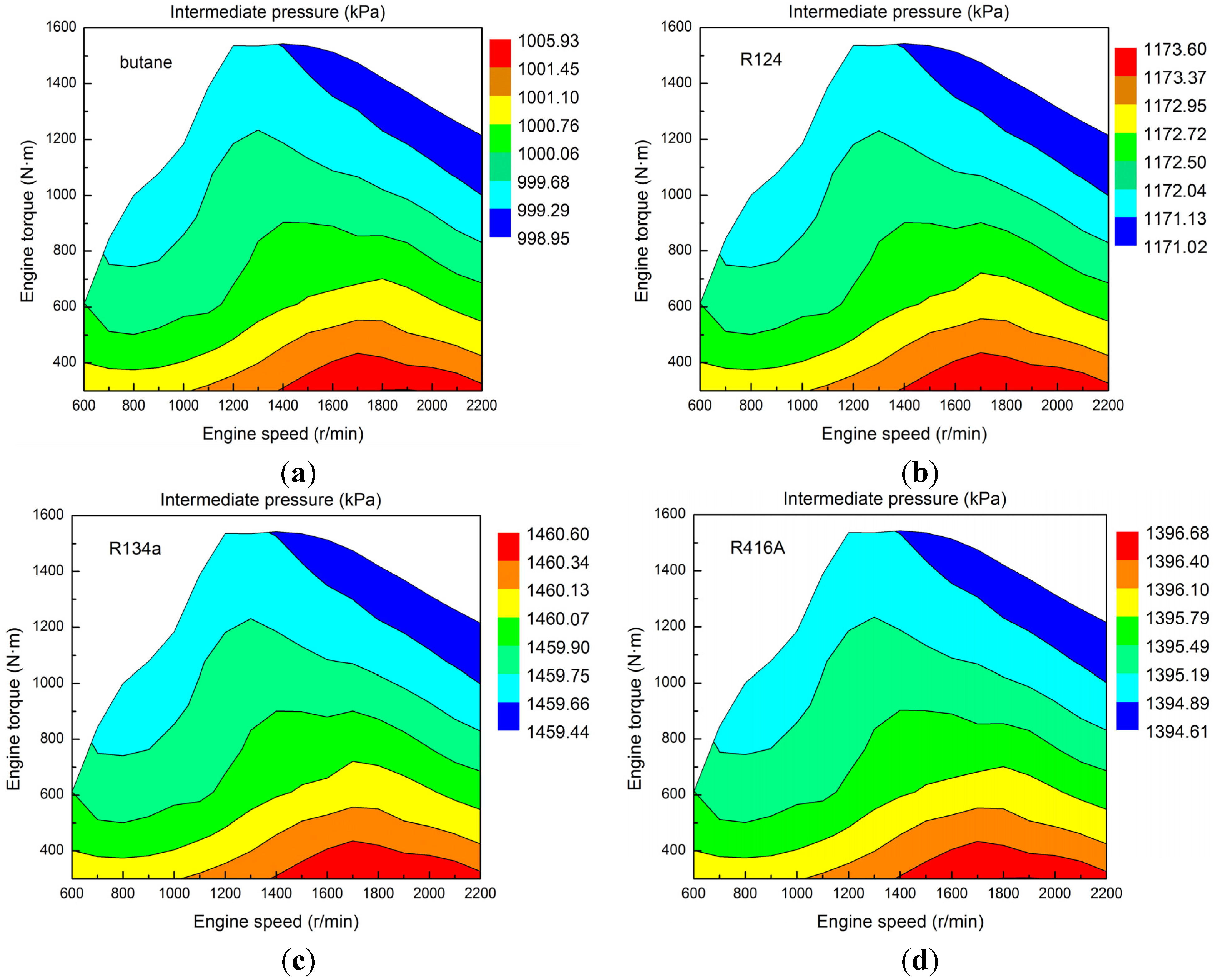
To obtain the optimal net power output and exergy destruction rate of the RORC system, for certain operating conditions of the diesel engine, the optimal values for evaporating pressure, intermediate pressure, and degree of superheat should be known with certainty. In this research, for the four selected working fluids, under various operating conditions of the diesel engine, the optimal evaporating pressure is 2.5 MPa, the amplitude of the optimized intermediate pressure variation is below 7 kPa, and the amplitude of the optimized degree of superheat variation is below 2 K.
(2)
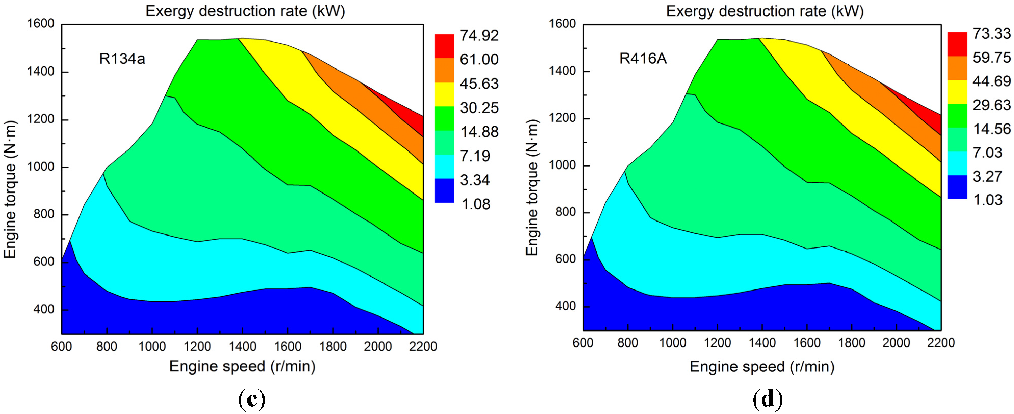
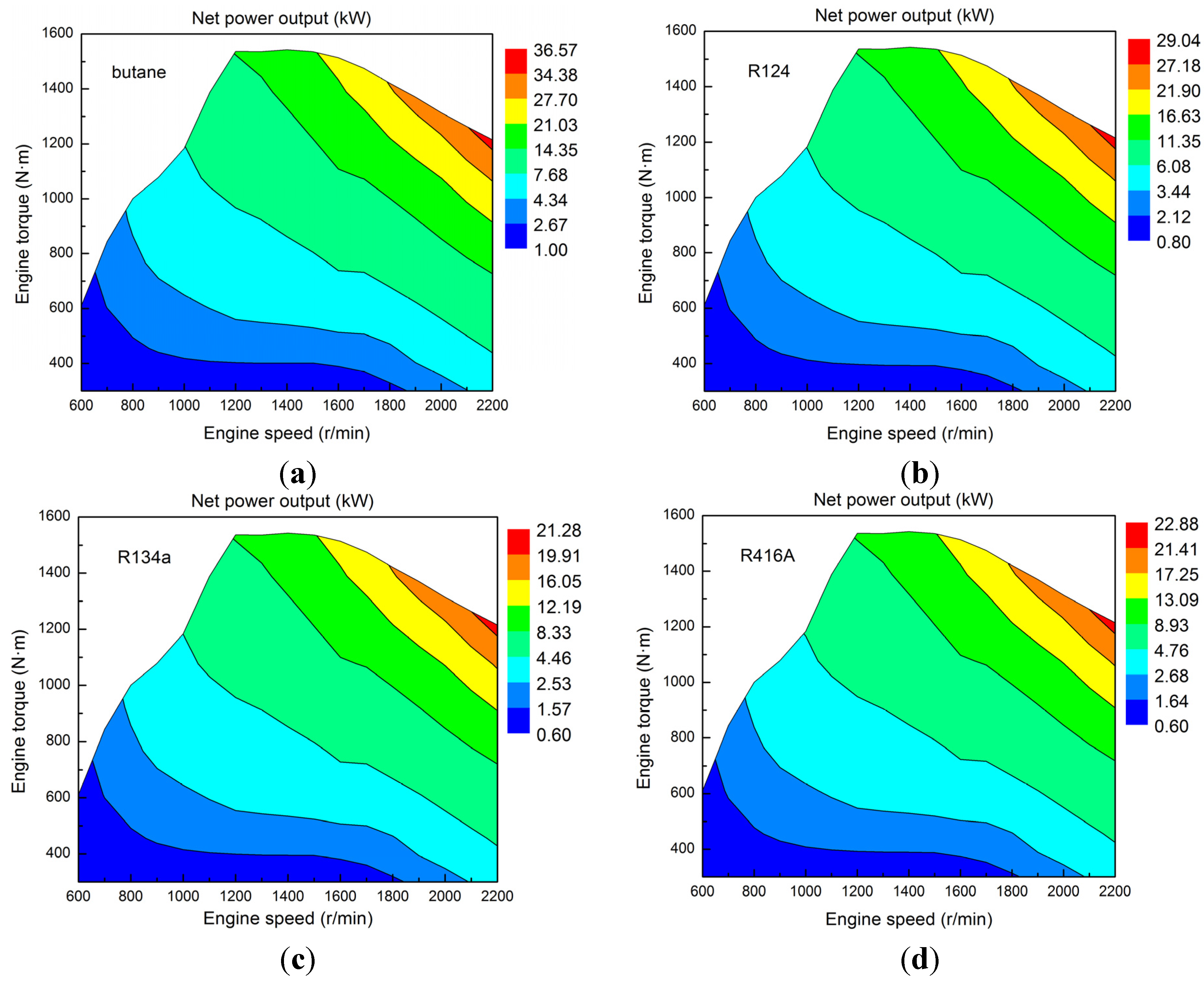
The required mass flow rate of the working fluid should vary with operating condition of the diesel engine. Among the four selected working fluids, the net power output of the RORC system using butane is the maximum, and the required mass flow rate of butane is the minimum. Accordingly, the total weight of the RORC system using butane can be reduced, and the risk of environmental pollution can be significantly decreased.
(3)
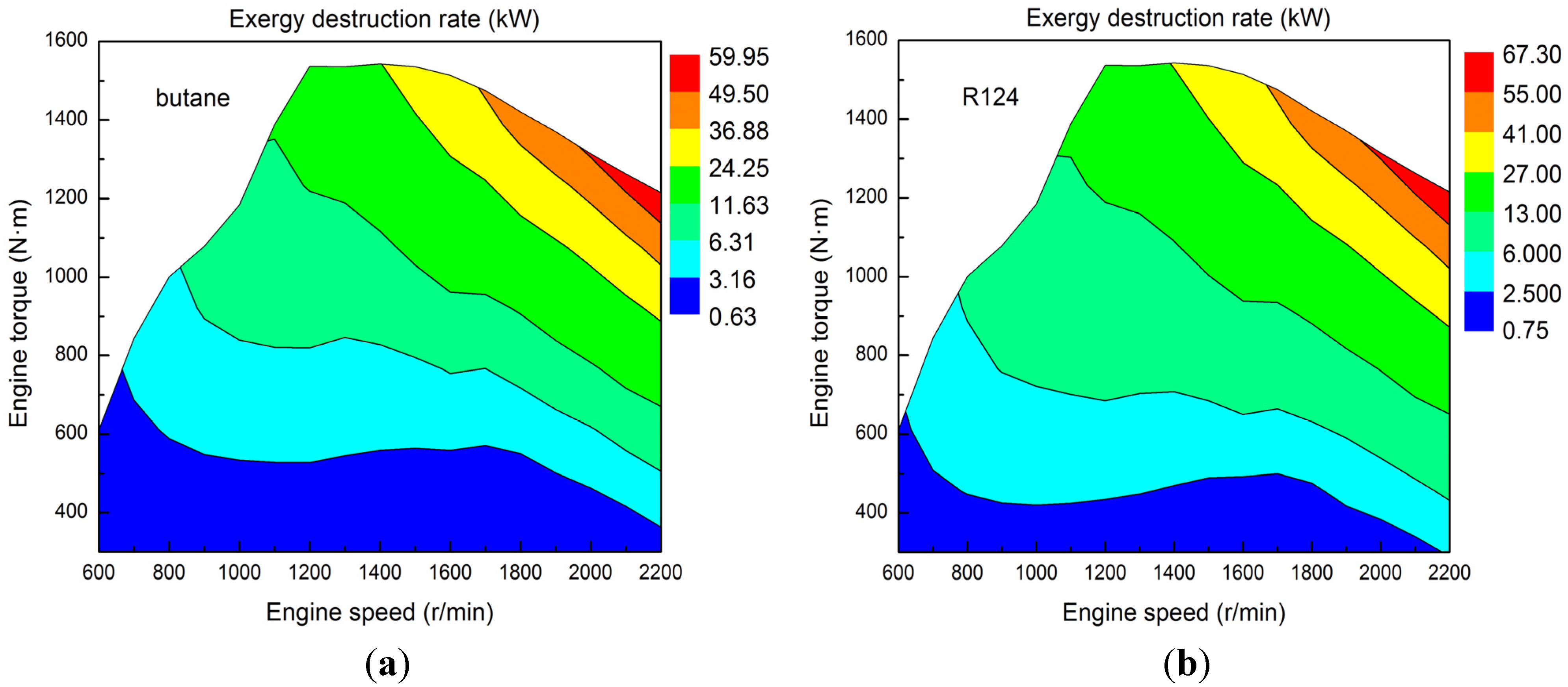
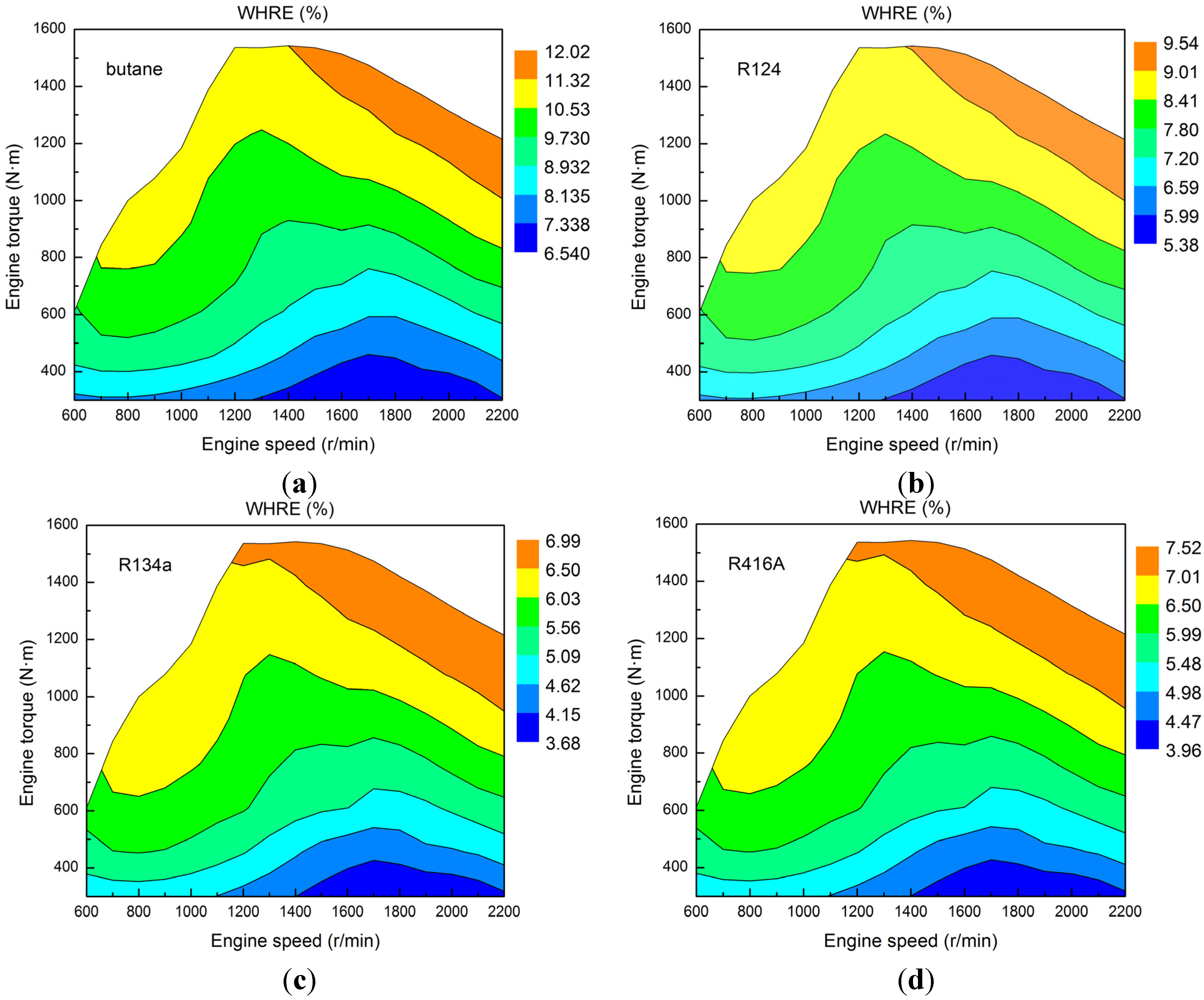
Considering the operating performances of the RORC system, the order of the working fluid selection decreasing in sequence is as follows: butane > R124 > R416A > R134a. When the engine speed is 2200 r/min and engine torque is 1215 N·m, the net power output of the RORC system using butane is 36.57 kW, and the WHRE of the RORC system using butane is 12.02%.
(4)
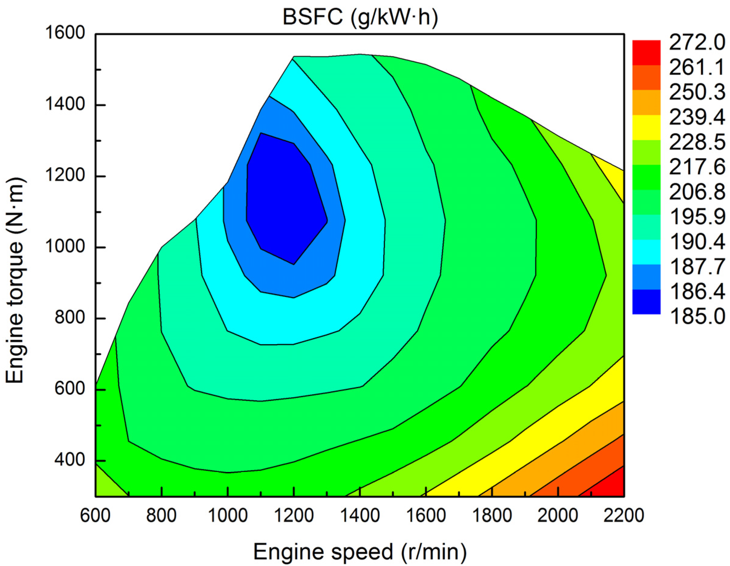
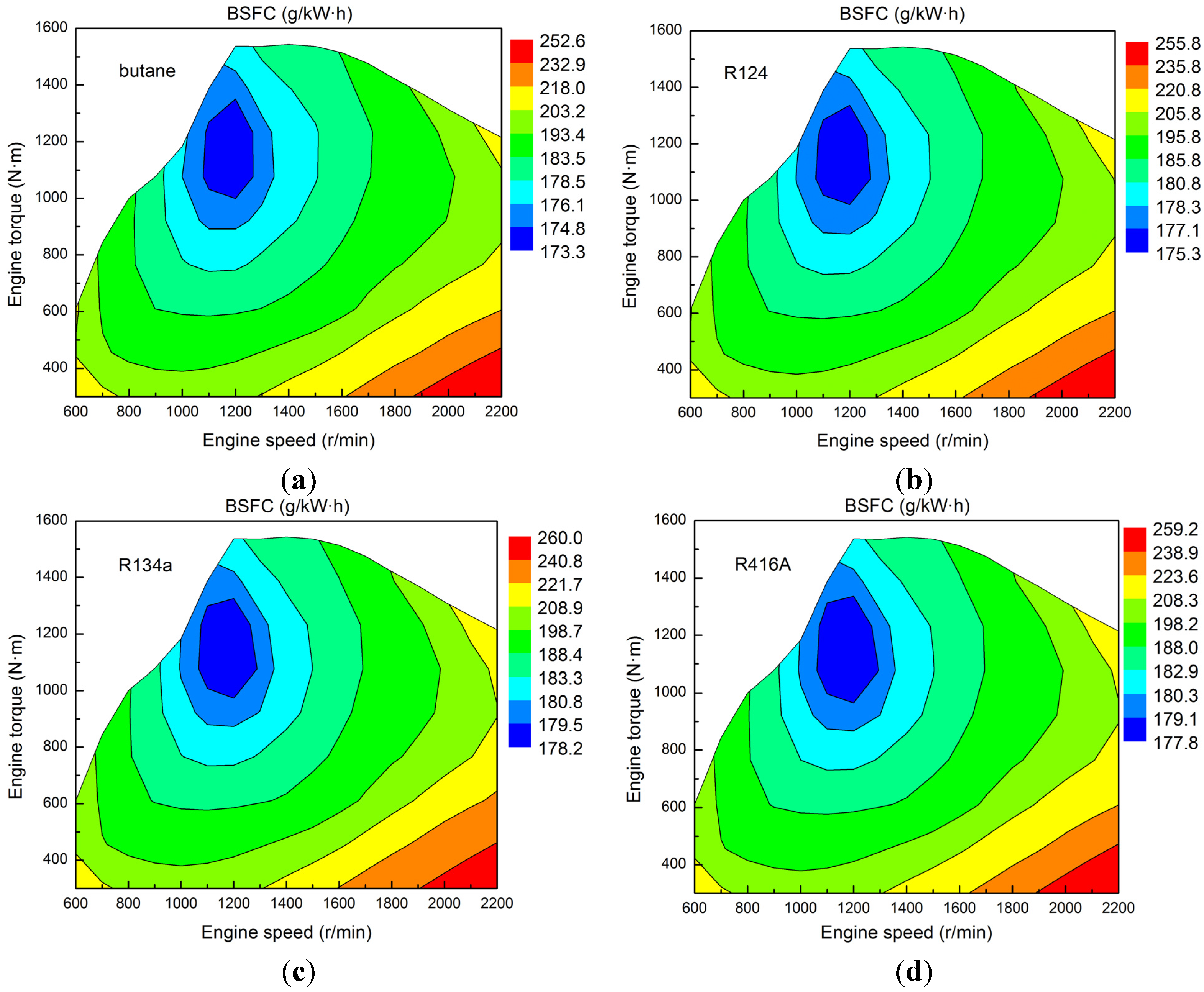
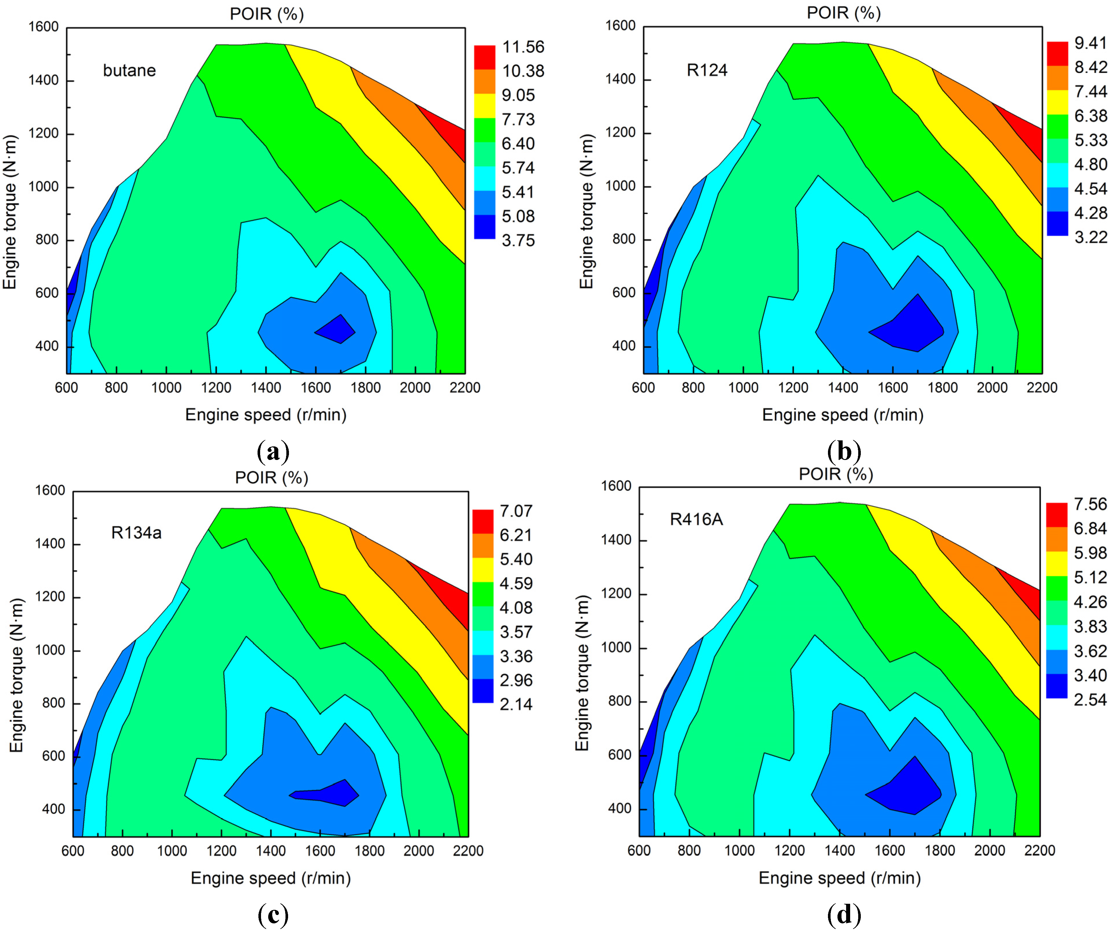
For the diesel engine-RORC combined system, the improvements in power output and fuel economy are significant. When the engine speed is 1131 r/min and engine torque is 1200 N·m, the BSFC of the combined system using butane is 173.3 g/kW·h, and the maximum improvement in BSFC of the combined system using butane is 11.56%. When the engine speed is 2200 r/min and engine torque is 1215 N·m, the POIR of the combined system using butane is 11.56%.

Acknowledgments

This work was sponsored by the Beijing Natural Science Foundation Program (Grant No. 3152005), the National Natural Science Foundation of China (Grant No. 51376011), the Scientific Research Key Program of Beijing Municipal Commission of Education (Grant No. KZ201410005003), the Key Project of Thirteenth Scientific Research Foundation for Graduate Students in Beijing University of Technology (Grant No. ykj-2014-10708), and the Project of Thirteenth Scientific Research Foundation for Graduate Students in Beijing University of Technology (Grant No. ykj-2014-10780).

Author Contributions

Hongjin Wang wrote the main body of the paper. Hongguang Zhang, Fubin Yang and Songsong Song revised the paper. Ying Chang, Chen Bei and Kai Yang performed the experiments. All authors read and approved the manuscript.

Conflicts of Interest

The authors declare no conflict of interests.

Nomenclature

Q ˙ exh
maximum available exhaust energy rate (kW)
W ˙ eng
effective power output of the diesel engine (kW)
W ˙ net
net power output (kW)
I ˙
exergy destruction rate (kW)
Texh
exhaust temperature at evaporator inlet (K)
Tout
exhaust temperature at evaporator outlet (K)
m ˙ f
fuel consumption rate of the diesel engine (g/h)
W ˙
power (kW)
Q ˙
heat transfer rate (kW)
T
temperature (K)
P
pressure (MPa)
h
enthalpy (kJ/kg)
m ˙
mass flow rate (kg/s)
T0
ambient temperature (K)
H
pump head (m)
g
gravitational acceleration (m/s2)
Nmax
maximum iteration number
n
current iteration
K
population size
pbest
personal best position
gbest
global best position
rand1
random number 1
rand2
random number 2
c1
acceleration coefficient 1
c2
acceleration coefficient 2
D
dimension of search space
bsfc
brake specific fuel consumption

Acronyms

ORC
organic Rankine cycle
RORC
regenerative organic Rankine cycle
OFOH
open feed organic fluid heater
BSFC
brake specific fuel consumption
POIR
power output increasing rate
ODP
ozone depletion potential
GWP
global warming potential
WHRE
waste heat recovery efficiency

Greek Letters

cp,exh
exhaust specific heat at constant pressure (kJ/kg·K)
ηe
heat exchange coefficient of the evaporator
ηt
isentropic efficiency of expander
α
fraction of vapor extracted (%)
ω
inertia weight
x
position of particle
v
velocity of particle

Subscripts

1, 2, 2s, 3, 3s, 4, 5, 6, 7
state points in cycle (as shown in Figure 8)
cs
combine system
cri
critical
t
expander
L
low-temperature heat source
f
fuel
e
evaporator
p1
Pump 1
p2
Pump 2
p3
Pump 3
w
water
w1
cooling water at the inlet of the condenser
w2
cooling water at the outlet of the condenser
o
organic working fluid
con
condenser
exh
exhaust
eng
diesel engine
max
maximum
min
minimum
out
outlet
net
net power output
sa
saturation

References

  1. Bari, S.; Hossain, S.N. Waste heat recovery from a diesel engine using shell and tube heat exchanger. Appl. Therm. Eng. 2013, 61, 355–363. [Google Scholar] [CrossRef]
  2. Dolz, V.; Novella, R.; García, A.; Sánchez, J. HD diesel engine equipped with a bottoming Rankine cycle as a waste heat recovery system. Part 1: Study and analysis of the waste heat energy. Appl. Therm. Eng. 2012, 36, 269–278. [Google Scholar] [CrossRef]
  3. Wang, Z.Q.; Zhou, N.J.; Guo, J.; Wang, X.Y. Fluid selection and parametric optimization of organic Rankine cycle using low temperature waste heat. Energy 2012, 40, 107–115. [Google Scholar] [CrossRef]
  4. Reverberi, A.; Borghi, A.D.; Dovì, V. Optimal design of cogeneration systems in industrial plants combined with district heating/cooling and underground thermal energy storage. Energies 2011, 4, 2151–2165. [Google Scholar] [CrossRef]
  5. Shu, G.; Liu, L.; Tian, H.; Wei, H.; Yu, G. Parametric and working fluid analysis of a dual-loop organic Rankine (DORC) used in engine waste heat recovery. Appl. Energy 2014, 113, 1188–1198. [Google Scholar] [CrossRef]
  6. Wang, E.; Zhang, H.; Fan, B.; Wu, Y. Optimized performances comparison of organic Rankine cycles for low grade waste heat recovery. J. Mech. Sci. Technol. 2012, 26, 2301–2312. [Google Scholar] [CrossRef]
  7. Di Battista, D.; Mauriello, M.; Cipollone, R. Waste heat recovery of an ORC-based power unit in a turbocharged diesel engine propelling a light duty vehicle. Appl. Energy 2015, 152, 109–120. [Google Scholar] [CrossRef]
  8. Zhang, J.; Feng, J.; Zhou, Y.; Fang, F.; Yue, H. Linear active disturbance rejection control of waste heat recovery systems with organic Rankine cycles. Energies 2012, 5, 5111–5125. [Google Scholar] [CrossRef] [Green Version]
  9. Katsanos, C.O.; Hountalas, D.T.; Pariotis, E.G. Thermodynamic analysis of a Rankine cycle applied on a diesel truck engine using steam and organic medium. Energy Convers. Manag. 2012, 60, 68–76. [Google Scholar] [CrossRef]
  10. Zhang, J.; Zhang, H.; Yang, K.; Yang, F.; Wang, Z.; Zhao, G.; Liu, H.; Wang, E.; Yao, B. Performance analysis of regenerative organic Rankine cycle (RORC) using the pure working fluid and the zeotropic mixture over the whole operating range of a diesel engine. Energy Convers. Manag. 2014, 84, 282–294. [Google Scholar] [CrossRef]
  11. Wei, M.; Song, P.; Zhao, B.; Shi, L.; Wang, Z.; Ma, C. Unsteady flow in the suction process of a scroll expander for an ORC waste heat recovery system. Appl. Therm. Eng. 2015, 78, 460–470. [Google Scholar] [CrossRef]
  12. Xie, H.; Yang, C. Dynamic behavior of Rankine cycle system for waste heat recovery of heavy duty diesel engines under driving cycle. Appl. Energy 2013, 112, 130–141. [Google Scholar] [CrossRef]
  13. Gao, H.; Liu, C.; He, C.; Xu, X.; Wu, S.; Li, Y. Performance analysis and working fluid selection of a supercritical organic Rankine cycle for low grade waste heat recovery. Energies 2012, 5, 3233–3247. [Google Scholar] [CrossRef]
  14. Li, Y.R.; Du, M.T.; Wu, C.M.; Wu, S.Y.; Liu, C. Potential of organic Rankine cycle using zeotropic mixtures as working fluids for waste heat recovery. Energy 2014, 77, 509–519. [Google Scholar] [CrossRef]
  15. Roy, J.P.; Misra, A. Parametric optimization and performance analysis of a regenerative Organic Rankine Cycle using R-123 for waste heat recovery. Energy 2012, 39, 227–235. [Google Scholar] [CrossRef]
  16. Wang, E.H.; Zhang, H.G.; Fan, B.Y.; Ouyang, M.G.; Zhao, Y.; Mu, Q.H. Study of working fluid selection of organic Rankine cycle (ORC) for engine waste heat recovery. Energy 2011, 36, 3406–3418. [Google Scholar] [CrossRef]
  17. Feidt, M.; Kheiri, A.; Pelloux-Prayer, S. Performance optimization of low-temperature power generation by supercritical ORCs (organic Rankine cycles) using low GWP (global warming potential) working fluids. Energy 2014, 67, 513–526. [Google Scholar]
  18. Aghahosseini, S.; Dincer, I. Comparative performance analysis of low-temperature Organic Rankine Cycle (ORC) using pure and zeotropic working fluids. Appl. Therm. Eng. 2013, 54, 35–42. [Google Scholar] [CrossRef]
  19. Xi, H.; Li, M.J.; Xu, C.; He, Y.L. Parametric optimization of regenerative organic Rankine cycle (ORC) for low grade waste heat recovery using genetic algorithm. Energy 2013, 58, 473–482. [Google Scholar] [CrossRef]
  20. Sun, Z.; Wang, J.; Dai, Y.; Wang, J. Exergy analysis and optimization of a hydrogen production process by a solar-liquefied natural gas hybrid driven transcritical CO2 power cycle. Int. J. Hydrog. Energy 2012, 37, 18731–18739. [Google Scholar] [CrossRef]
  21. Feng, Y.; Zhang, Y.; Li, B.; Yang, J.; Shi, Y. Sensitivity analysis and thermoeconomic comparison of ORCs (organic Rankine cycles) for low temperature waste heat recovery. Energy 2015, 82, 664–677. [Google Scholar] [CrossRef]
  22. Xiao, L.; Wu, S.Y.; Yi, T.T.; Liu, C.; Li, Y.R. Multi-objective optimization of evaporation and condensation temperatures for subcritical organic Rankine cycle. Energy 2015, 83, 723–733. [Google Scholar] [CrossRef]
  23. Mamaghani, A.H.; Najafi, B.; Shirazi, A.; Rinaldi, F. 4E analysis and multi-objective optimization of an integrated MCFC (molten carbonate fuel cell) and ORC (organic Rankine cycle) system. Energy 2015, 82, 650–663. [Google Scholar] [CrossRef]
  24. Hu, M.; Cho, H. A probability constrained multi-objective optimization model for CCHP system operation decision support. Appl. Energy 2014, 116, 230–242. [Google Scholar] [CrossRef]
  25. Boyaghchi, F.A.; Heidarnejad, P. Thermoeconomic assessment and multi objective optimization of a solar micro CCHP based on organic Rankine cycle for domestic application. Energy Convers. Manag. 2015, 97, 224–234. [Google Scholar] [CrossRef]
  26. Yang, K.; Zhang, H.; Song, S.; Yang, F.; Liu, H.; Zhao, G.; Zhang, J.; Yao, B. Effects of degree of superheat on the running performance of an organic Rankine cycle (ORC) waste heat recovery system for diesel engines under various operating conditions. Energies 2014, 7, 2123–2145. [Google Scholar] [CrossRef]
  27. Song, S.; Zhang, H.; Lou, Z.; Yang, F.; Yang, K.; Wang, H.; Bei, C.; Chang, Y.; Yao, B. Performance analysis of exhaust waste heat recovery system for stationary CNG engine based on organic Rankine cycle. Appl. Therm. Eng. 2011, 76, 301–309. [Google Scholar] [CrossRef]
  28. Zhang, H.; Wang, E.; Fan, B. A performance analysis of a novel system of a dual loop bottoming organic Rankine cycle (ORC) with a light-duty diesel engine. Appl. Energy 2013, 102, 1504–1513. [Google Scholar] [CrossRef]
  29. Liu, Q.; Shen, A.; Duan, Y. Parametric optimization and performance analyses of geothermal organic Rankine cycles using R600a/R601a mixtures as working fluids. Appl. Energy 2015, 148, 410–420. [Google Scholar] [CrossRef]
  30. Li, N.J.; Wang, W.J.; Hsu, C.C.J. Hybrid particle swarm optimization incorporating fuzzy reasoning and weighted particle. Neurocomputing 2015, 167, 488–501. [Google Scholar] [CrossRef]
  31. Mohammadi-Ivatloo, B.; Rabiee, A.; Soroudi, A.; Ehsan, M. Iteration PSO with time varying acceleration coefficients for solving non-convex economic dispatch problems. Int. J. Electr. Power Energy Syst. 2012, 42, 508–516. [Google Scholar] [CrossRef]

