Article

Incorporating Cyber Layer Failures in Composite Power System Reliability Evaluations

1
College of Electrical Engineering, Zhejiang University, Hangzhou 310027, China
2
State Grid Energy Research Institute, Beijing 102209, China
*
Author to whom correspondence should be addressed.
Energies 2015, 8(9), 9064-9086; https://doi.org/10.3390/en8099064
Submission received: 27 May 2015 / Revised: 11 August 2015 / Accepted: 19 August 2015 / Published: 26 August 2015
(This article belongs to the Special Issue Resilience of Energy Systems)

Abstract

:
This paper proposes a novel approach to analyze the impacts of cyber layer failures (i.e., protection failures and monitoring failures) on the reliability evaluation of composite power systems. The reliability and availability of the cyber layer and its protection and monitoring functions with various topologies are derived based on a reliability block diagram method. The availability of the physical layer components are modified via a multi-state Markov chain model, in which the component protection and monitoring strategies, as well as the cyber layer topology, are simultaneously considered. Reliability indices of composite power systems are calculated through non-sequential Monte-Carlo simulation. Case studies demonstrate that operational reliability downgrades in cyber layer function failure situations. Moreover, protection function failures have more significant impact on the downgraded reliability than monitoring function failures do, and the reliability indices are especially sensitive to the change of the cyber layer function availability in the range from 0.95 to 1.

1. Introduction

With the latest developments in communication and embedded computing, traditional power grids are now integrated with networked embedded computing and communication systems, offering the chance to improve the power grid reliability, efficiency and operation resilience [1]. The modern power grid is a complex Cyber-Physical Energy System (CPES), in which the cyber and physical layers incorporate and interdepend on each other. The physical layer refers to electrical devices that fulfill the tasks of power generation, transmission and distribution to customers, while the cyber layer (automation system) accomplishes data gathering, analysis and information transmission to monitor and protect the physical layer [2,3]. The cyber layer can further be categorized as protection and monitoring subsystems according to their functions. To accomplish the protection function, digital relays, merging units, protection intelligent electronic devices and Ethernet switches are all involved to provide comprehensive and real-time protection to the physical layer components. In addition, the monitoring function continuously supervises electrical components’ operation states and sends alarms to the grid operator. While the cyber layer is deployed to improve the performance of the physical layer, its own complexity, uncertainty and the interaction between the two layers introduces new sources of reliability threats. It is therefore necessary to analyze the impacts of such new sources of reliability threats [4].
The relationship between the cyber layer and the physical layer can be classified as direct and indirect interdependences [3,5,6]. Indirect interdependence means that failures occurring in the cyber layer would not stop the operation of the power device immediately, but would impact the performance of the device when failures happen in that electrical device or its adjacent devices. Protection and monitoring are two kinds of indirect interdependences [7].
In recent years, increasing attention has been paid to reliability evaluation incorporating the impact(s) of protection failures. There are two major failure modes in the protection system: failures-to-operate and undesired-tripping [8]. Fundamental research has been done to identify the effects of protection failures on power systems and incorporate protection failures into power system reliability evaluations [8,9,10,11,12,13]. The model of electrical components with their associated protection systems proposed by Singh and Patton [9] is an effective way to model electrical components for reliability analysis. However, that model does not differentiate between the two protection failure modes. The multi-state Markov chain with different protection failures modes has been proposed in [10] and the failure rate of the protection system has been modeled as a function of impedance seen by the relay for distance protection and the current seen by the relay for over-current protection. The concept of “unit-zone” and the completed electrical components Markov-chain model incorporating three stages of protection failures have been introduced in [14,15]. Despite these efforts, the methodology for evaluating reliability incorporating protection failures still need further research for two reasons: 1) the existing methods do not include each device’s protection strategy and the failure rate of the protection function for all the devices is set to be the same constant value, however, that is not practical and not suitable for the CPES, since the failure rate of the protection function is associated with three factors, which are the component’s protection strategy, its role as the backup protection for different adjacent devices, as well as the topology and reliability data of the cyber layer, and 2) the developed multi-state Markov-chain models are based on the assumption that the Mean Time to Repair (MTTR) of the protection system is less than that of the protected device, when in fact, the MTTR of transformers is usually longer than that of the protection systems.
In the aspects of the monitoring function and its application, the monitored components are mostly transformers and circuit breakers [16]. The monitoring of power transformer winding temperature is critical for the reliable operation of the power system [17]. There is a significant improvement of the reliability indices of circuit breakers when the monitoring system is applied [18]. Aging monitoring systems have been taken into consideration in the reliability assessment of circuit breakers [19]. Reference [20] has explored the effect of monitoring system failures on the repair rate and failure rate of electrical components based on a Markov chain model. However, these works all focus on the device or substation level, and the repair and failures of the monitoring system are not incorporated in the development of the monitored device model. The separate research on protection failures and monitoring failures above could not determine the actual reliability level of power systems. It is essential to develop a quantitative analysis approach to evaluate the reliability of composite power systems in the background of the CPES.
This paper presents an approach to incorporate the failures of cyber layer functions into reliability evaluations of composite power systems. First, the reliability of the cyber layer and its functions with various topologies are calculated with the Reliability Block Diagram (RBD) method, and then the impacts from the cyber layer function failures on the availability of the physical layer components are modeled via the multi-state Markov chain model. After obtaining the modified reliability and availability of components, the composite power systems reliability indices are evaluated through non-sequential Mont-Carlo simulation. The main contributions of this paper are as follows:
(1)
The cyber layer of the CPES is subdivided into two subsystems to accomplish the function of protection and monitoring from a function-oriented perspective. The RBD method is used to calculate the availability and reliability of protection and monitoring functions, which builds the relationship between the cyber layer function reliability and that of the cyber layer topology.
(2)
The multi-state Markov chain model of electrical components is built, considering the topology of the cyber layer and the reliability of the cyber layer functions, as well as physical components’ actual protection and monitoring strategies simultaneously.
The remainder of the paper is organized as follows: Section 2 introduces the cyber layer configurations and its functions in the CPES, and the RBD method is used to calculate the reliability of the cyber layer functions. Section 3 formulates the completed multi-states Markov-chain model of components incorporating the cyber layer failures of protection and monitoring functions. Section 4 presents the procedure of composite power systems reliability evaluation through non-sequential Monte-Carlo simulation. Case studies on the Roy Billinton Test System (RBTS) are done in Section 5. The sensitivity analysis is conducted in Section 6 and Section 7 is conclusions.

2. Reliability Modeling of the Cyber Layer and Its Functions

The IEC61850 standard, which defines the communication protocols and basic cyber layer model architectures within substations, was put forward to achieve inter-operability among different automation devices. In addition, applications are in service to expand the scope of IEC 61850 to wide area substation-to-substation communication [21]. In this section, the focus is on the application of cyber layer model architectures according to IEC 61850 for wide area multi-substation systems and obtaining the function-oriented cyber layer reliability data.

2.1. Cyber Layer Critical Elements

The cyber layer functions are implemented by correctly connection and working of cyber layer elements. Merging Units, Intelligent Electronic Devices and Ethernet Switches are critical in the cyber layer data sampling, data transmission and processing. The following is a general description of the roles of those elements in the cyber layer:
(1)
Merging Unit (MU). The merging unit is an integral part to fulfill the task of monitoring and protection, which combines functions of collecting data to monitor the states of high voltage electrical components and sending messages via the Ethernet network to the control center.
(2)
Intelligent Electronic Device (IED). Intelligent Electronic Devices, like the Protection IED (Prot IED), Monitoring IED (Mont IED) and Control IED (Cont IED), are interface devices between the electrical physical layer and the cyber layer with advanced local control and bidirectional information transmitting ability.
(3)
Ethernet Switch (ES). The Ethernet switch, which receives, processes and transmits data to the destination device based on packet switching theory, connects the cyber layer devices and decides the direction of information flow within the cyber layer network. Several layouts of Ethernet switches can form various different cyber network topologies.

2.2. The Cyber Layer Model within the Substation

For reasons of simplicity, the substation is shown as one bus connecting to one transmission line and one generating unit. Circuit breakers are located at two ends of each transmission line and the connecting point of the generating units to the substation bus. The cyber layer connection within the substation of the CPES is shown in Figure 1.
Figure 1. The cyber layer connection within the substation.
Energies 08 09064 g001
Merging units collect the operation status of transmission lines, transformers, generators and circuit breakers. Control IEDs, Monitoring IEDs and Protection IEDs are acting as the interface connecting the physical layer and the cyber layer. At the same time, the IEDs transmit upward information to the control center and downward commands to the physical layer components to involve the implementation of the cyber layer function. The Ethernet switch connects the cyber layer components within each substation and other Ethernet switches. The optical fiber is the connection media of the cyber layer.

2.3. Reliability Calculation of the Cyber Layer Monitoring and Protection Functions

The primary task of the cyber layer is to monitor, protect and control the electrical physical layer. The protection system and monitoring system are two subsystems of the cyber layer subdivided from a function-oriented perspective. The monitoring and protection subsystems share the same information transmission buses, Ethernet switches, merging units and the control center severs. However, they accomplish protection and monitoring functions using different kinds of IEDs within substations. Basic architectures of the cyber layer include cascading, star and star-ring topologies. To get a reasonable and conservative result of the cyber layer reliability, it is necessary to guarantee all the cyber layer devices should be in normal state for the communication and executing commands between the control center and the extreme end IED. Accomplishing the protection and monitoring functions involves the cyber layer devices needed and they should to be in normal state [21]. Therefore, it is reasonable to regard the reliability and availability of the cyber layer protection function and monitoring function are equal to those of the involved cyber layer components connecting in certain topology. The reliability and availability of the cascading topology and star-ring topology are calculated based on RBD method [22].

2.3.1. Cascading Topology

A typical cascading topology of the cyber layer is illustrated in Figure 2. The Ethernet switches are connected without any loop or redundancy and all the substation Ethernet switches should work for the transmission of information between the control center and the extreme end IED.
Figure 2. A typical cascading topology of the cyber layer.
Energies 08 09064 g002
The RBD for the cyber layer functions in cascading topology is shown in Figure 3.
Figure 3. The RBD for the cascading topology.
Energies 08 09064 g003
To fulfill the cyber layer function, all the components involved should be in normal state. Therefore in the RBD, the devices are connected in series. To calculate the reliability, the optical fiber, as the information transmitting bus, is supposed to be fully available [23]. The Mean Time to Failure (MTTF) and availability of the cyber layer functions in the cascading topology as Figure 3 can be obtained as follows:
M T T F P r o s y s t e m c a s = 1 1 M T T F M U + 1 M T T F P r o I E D + N S u b s t a t i o n S W M T T F S u b s t a t i o n S W + 1 M T T F C o n t r o l c e n t e r S W + 1 M T T F S e r v e r + 1 M T T F H M I
M T T F M o n t s y s t e m c a s = 1 1 M T T F M U + 1 M T T F M o n t I E D + N S u b s t a t i o n S W M T T F S u b s t a t i o n S W + 1 M T T F C o n t r o l c e n t e r S W + 1 M T T F S e r v e r + 1 M T T F H M I
A Pr o s y s t e m c a s = A M U A Pr o I E D A S u b s t a t i o n S W N S u b s t a t i o n S W A C o n t r o l c e n t e r S W A S e r v e r A H M I
A M o n t s y s t e m c a s = A M U A M o n t I E D A S u b s t a t i o n S W N S u b s t a t i o n S W A C o n t r o l c e n t e r S W A S e r v e r A H M I
where Pro IED means Protection Intelligent Electronic Device, Mont IED means Monitoring Intelligent Electronic Device, Cont IED means Control Intelligent Electronic Device and HMI means Human Machine Interface, respectively. M T T F M U , M T T F S u b s t a t i o n S W , M T T F S e r v e r , M T T F H M I and M T T F P r o I E D are the MTTF of merging units, Ethernet switches, servers, HMI and Protection IEDs, respectively. N S u b s t a t i o n S W means the number of substation Ethernet switches, A M U , A S u b s t a t i o n S W , A S e r v e r , A H M I , A Pr o I E D and A C o n t r o l c e n t e r S W are the availability of merging units, station Ethernet switches, servers, HMI, Protection IEDs and control center Ethernet switches, respectively. Equation (1) calculates the MTTF of the cyber layer protection function for the cascading topology, Equation (2) calculates the MTTF of the cyber layer monitoring function for the cascading topology, Equation (3) and Equation (4) calculate the availability of the cyber layer protection function and monitoring function for the cascading topology, respectively.

2.3.2. Star-ring Topology

A typical star-ring topology of the cyber layer is illustrated in Figure 4.
Figure 4. A typical star-ring topology of the cyber layer.
Energies 08 09064 g004
Two redundant control center Ethernet switches are connected in ring topology and act as redundant to each other, so they are in parallel connection in the RBD. Each substation Ethernet switch is connected directly to both of the control center Ethernet switches and does not connected to other substation Ethernet switches. Therefore, the RBD for the cyber layer function in star-ring topology is a combination of series and parallel connections of components as shown in Figure 5.
Figure 5. The RBD for the star-ring topology.
Energies 08 09064 g005
The MTTF and availability for the cyber layer functions as the star-ring topology shown in Figure 5 can be obtained using series and parallel combination of components:
A C o n t r o l c e n t e r S w i t c h P a r a l l e l = 1 ( 1 A S w i t c h ) 2
M T T R C o n t r l c e n t e r S w i t c h P a r a l l e l = M T T R S w i t c h 2
M T T F C o n t r o l c e n t e r S w i t c h P a r a l l e l = A S w i t c h P a r a l l e l M T T R S w i t c h P a r r a l l e l 1 A S w i t h P a r a l l e l
M T T F Pr o s y s t e m s t a r = 1 1 M T T F M U + 1 M T T F P r o I E D + 1 M T T F S u b s t a t i o n S W + 1 M T T F C o n t r o l c e n t e r S w i t c h P a r r a l + 1 M T T F S e r v e r + 1 M T T F H M I
M T T F M o n t s y s t e m s t a r = 1 1 M T T F M U + 1 M T T F M o n t I E D + 1 M T T F S u b s t a t i o n S W + 1 M T T F C o n t r o l c e n t e r S w i t c h P a r r a l + 1 M T T F S e r v e r + 1 M T T F H M I
A Pr o s y s t e m s t a r = A M U A Pr o I E D A S u b s t a t i o n S W A C o n t r o l c e n t e r S w i t c h P a r a l l e l A S e r v e r A H M I
A M o n t s y s t e m s t a r = A M U A M o n t I E D A S u b s t a t i o n S W A C o n t r o l c e n t e r S w i t c h P a r a l l e l A S e r v e r A H M I
where M T T F C o n t r l c e n t e r S w i t c h P a r a l l e l and A C o n t r o l c e n t e r S w i t c h P a r a l l e l demonstrate the MTTF and availability of two parallel connected control center Ethernet switches, respectively. M T T R C o n t r l c e n t e r S w i t c h P a r a l l e l represents MTTR of two parallel connected control center Ethernet switches. Equation (8) calculates the MTTF of the cyber layer protection function for the star-ring topology, Equation (9) calculates the MTTF of the cyber layer monitoring function for the star-ring topology, Equation (10) and Equation (11) calculate the availability of the cyber layer protection function and monitoring function for the star-ring topology, respectively.

3. Multi-state Markov Chain Model Incorporating the Cyber Layer Function Failures

In the Cyber-Physical Energy System, the functions of the cyber layer in this paper are referred as the protection and monitoring function, the protected devices in the physical layer including transmission lines, generators as well as transformers and the monitored devices in the physical layer including circuit breakers and transformers. To model the failure of the protection and monitoring functions failures of the cyber layer, the multi-state Markov chain model is adopted, the new added states are corresponding to the states considering the failure of the cyber layer protection and monitoring functions.

3.1. Multi-State Markov Chain Model Incorporating Protection Function Failures

The definition of a protection function failure is a defect that will cause relays or a relay system to incorrectly or inappropriately remove a circuit element as a direct consequence of another switch event [24]. There are two failure modes in protection failures. One is the fail-to-operate mode, which refers to undetected failures or faults of the protection system and is associated with the concept of unreadiness probability. The other is the undesired-tripping mode, in which an non-faulty component is tripped. The latter fault mode can further be categorized as spontaneous unwanted tripping and tripping by faults in adjacent components. Since spontaneous unwanted tripping can be remedied by an auto-reclose system, the fail-to-operate mode and undesired-tripping by faults outside the protection zone are focused on here. The protection system of certain electrical component is the backup protection of its adjacent components. When the protection system of a component fails, if a failure happens in that component, the adjacent component to it will be tripped unintentionally. In the process of reliability evaluation of composite power systems, the states of transmission lines and generating units are sampled, so the focus is on the formulation of multi-state Markov chain models of transmission lines and generating units, which incorporate the cyber layer protection function failures.

3.1.1. The Formulation of the Completed Markov Chain Model of Transmission Lines

The Markov chain model of transmission lines is built of two parts: A) the probability of the undesired-tripping caused by each of the adjacent transmission lines is calculated and B) the probability of the undesired-tripping caused by each of the adjacent transmission lines up is summed as the probability of undesired-tripping, and then the down state corresponding to the undesired-tripping as well as the others are included in the completed Markov chain model of transmission lines.

A) The calculation of the probability of each adjacent transmission lines acting as the source of the undesired-tripping

One transmission line to be modeled is regarded as the focused line and those connected to the same bus are regarded as the adjacent lines. The focused line and the corresponding cyber layer to fulfill the protection function are taken as one unit in the modeling. The probability that the adjacent line is in the up state with its corresponding protection system failed is equal to the probability that the adjacent line would act as the source of undesired-tripping for the focused line. The multi-state Markov chain model in Figure 6 is developed for each of the adjacent lines and the probability of state A3 is the probability of the adjacent line acting as the source of undesired-tripping of the focused line.
where:
  • State A1: the adjacent line and its corresponding cyber layer protection function are both good.
  • State A2: the adjacent line is failed while its corresponding cyber layer protection function is good.
  • State A3: the adjacent line is good while its corresponding cyber layer protection function has failed.
  • State A4: the adjacent line and its corresponding cyber layer protection function have both failed.
Figure 6. The multi-state Markov chain model to obtain the undesired-tripping risk.
Energies 08 09064 g006
where λpro and λ0 are the failure rate of the cyber layer protection function and transmission line, respectively. µpro and µ0 are the repair rate of the cyber layer protection function and transmission line, respectively. The assumptions are:
(1)
Failures of the adjacent line and its corresponding cyber layer protection function are independent to each other, and if the line and the protection function both fail, the repairs will be carried out simultaneously and are also independent.
(2)
“Fail-to-operate” and “undesired-trip” of the protection system do not overlap.
(3)
The backup protection and main protection of one line do not fail simultaneously.
Based on the Markov's limit theorem [25], the final state probability will converge to a constant. Here, PAi represents the probability of state Ai, P A i represents the stable state probability and P A demonstrates the stable state probability set:
P A = [ P A 1 P A 2 P A 3 P A 4 ] T
T is the transformation matrix of the multi-state Markov chain model:
T= [ 1 λ p r o λ 0 λ 0 λ p r o 0 μ 0 1 μ 0 0 0 0 0 1 λ 0 λ 0 μ p r o 0 0 1 μ p r o ]
T P A = P A
P A ( T I ) = 0
To calculate the final state probability of each state, Equation (16) is added to form the equation set, because there are three independent equations of all four equations in Equation (15):
P A 1 + P A 2 + P A 3 + P A 4 = 1
The Equation set (15,16) is solvable to obtain the stable state probability:
p 1 = λ 0 μ 0 μ p r o / ( λ 0 2 μ p r o + λ 0 λ p r o μ 0 + λ 0 μ 0 μ p r o + μ p r o λ p r o μ 0 ) p 2 = λ 0 2 μ p r o / ( λ 0 2 μ p r o + λ 0 λ p r o μ 0 + λ 0 μ 0 μ p r o + μ p r o λ p r o μ 0 ) p 3 = λ p r o μ 0 μ p r o / ( λ 0 2 μ p r o + λ 0 λ p r o μ 0 + λ 0 μ 0 μ p r o + μ p r o λ p r o μ 0 ) p 4 = λ 0 λ p r o μ 0 / ( λ 0 2 μ p r o + λ 0 λ p r o μ 0 + λ 0 μ 0 μ p r o + μ p r o λ p r o μ 0 )

B) The formulation of the completed multi-state Markov chain model

In this part, the multi-state Markov chain model is expanded to include the down state corresponding to undesired-tripping. The complete multi-state Markov chain model is shown as Figure 7. The down states of the focused line are decoupled into three parts. State A5 describes the undesired-tripping of the focused line as the backup protection of its failed adjacent lines; state A2 describes the failure of the focused line itself and state A4 describes that both the focused line and the protection function are failed. Definitions of states A1 and A3 are the same as those in Figure 6.
Figure 7. The completed multi-state Markov chain model of transmission lines incorporating protection function failures.
Energies 08 09064 g007
where λpro and λ0 are the failure rate of the cyber layer protection function and the focused line, respectively. µpro and µ0 are the repair rate of the cyber layer protection function and the focused line, respectively. i means the number of adjacent lines of the focused line. λi demonstrate the failure rate of the ith adjacent line. p3i is the probability of ith adjacent line in state A3 and i λ i p 3 i means the equivalent failure rate of undesired-tripping for the focused line. The method to derive each state probability in Figure 6 is the same as discussed in part A. The modified availability and unavailability of the focused line incorporating the protection function failures are obtained as follows:
P u p 1 = P A 1 + P A 3 , P d n 1 = P A 2 + P A 4 + P A 5
where Pup1 and Pdn1 are the availability and the unavailability of the focused line, respectively. The dependencies between adjacent transmission lines are decoupled in building the completed multi-states Markov chain of each transmission line as in Figure 7. Therefore, the modified availability and unavailability of each transmission line expressed in Equation (18) decouple the sequences of dependences to the failure of its adjacent lines, but still have incorporated the effects of dependencies between adjacent lines caused by cyber layer function failure.

3.1.2. The Formulation of the Completed Markov Chain Model of Generating Units

In the physical layer of the CPES, the generator and the transformer that connects the generator to the substation bus are in series connection. Therefore, they are treated as the generating unit in the modeling. Various categories of protections are applied to generators and transformers. For transformers, the main protection includes differential protection and gas protection, and the backup protection includes over-current protection and over-load protection. The protection strategies of generators and transformers are different from those of transmission lines, since the backup protection of generators and transformers are implemented within themselves and would not trigger their adjacent components undesired-tripping. To build the multi-state Markov chain model of the generating unit, it is not necessary to consider adjacent components as the source of undesired-tripping, also, in real operation, the protection of generators and transformers do not act as the backup protection for their adjacent transmission lines for the safety and stability of power grids operation. Based on the analysis above, there are two down states in the completed Markov chain model of generating units. One is corresponding to the failure of the generating unit itself and the other is corresponding to the failure of both the generating unit and its corresponding cyber layer protection function. The completed Markov model of the generating unit is in Figure 8. Besides assumptions for Figure 6, another assumption is that the failure of the generator or the transformer both leads to the generating unit failures, because of the series connection of the generating unit, where:
State A1: the generating unit and its corresponding cyber layer protection function are both good.
State A2: the transformer in the generating unit is failed while its corresponding cyber layer protection function is good.
State A3: the generator in the generating unit is failed while its corresponding cyber layer protection function is good.
State A4: the generating unit is good while its corresponding cyber layer protection function has failed.
State A5: the transformer in the generating unit and its corresponding cyber layer protection function have both failed.
State A6: the generator in the generating unit and its corresponding cyber layer protection function have both failed.
Figure 8. The completed multi-state Markov chain model of generating units incorporating protection function failures.
Energies 08 09064 g008
where λpro, λt and λg are the failure rate of the cyber layer protection function, transformer and generator, respectively. µpro, µt and µg are the repair rate of the cyber layer protection function, transformer and generator, respectively. min (µt, µpro) means the min value of µt and µpro. min (µg, µpro) demonstrates the min value of µg and µpro.
The method to derive each state probability in Figure 8 is the same as that in Section 3.1. The modified availability and unavailability of the generating unit incorporating the protection function failures are obtained as follows:
P u p 2 = P A 1 + P A 4 , P d n 2 = P A 2 + P A 3 + P A 5 + P A 6
where Pup2 and Pdn2 are the availability and the unavailability of the modeled generating unit, respectively.

3.2. Multi-State Markov Chain Model Incorporating Monitoring Function and Its Failures

The monitoring system encompasses the duties of collecting and transferring the operation data, like the Supervisory Control and Data Acquisition (SCADA) type measurements and condition data, to the network control center. In the CPES environment, the monitoring function of the cyber layer involves more advanced features, such as online visualization, indication and data manipulation.
The cyber layer monitoring function impacts the physical layer reliability through the preventive and the corrective measures. Preventive measures include pre-defined remedial actions to derate power equipment stress, and corrective measures help operators to observe and locate failures. Therefore, the preventive and the corrective actions reduce the MTTR and increase the MTTF to enhance the monitored component reliability. In composite power systems, transformers are expensive and vital equipment in substations and circuit breakers need to be monitored to guarantee reliable operation and the control of electrical components. Therefore, the multi-state Markov chain model of transformers and circuit breakers are developed in this section.
The monitored component with its cyber layer monitoring function is taken as a unit in the modeling. New normal states and down states are added in the model of the two stationary states Markov chain. The model including the monitoring function is shown in Figure 9:
  • State A1: the component and its corresponding cyber layer monitoring function are both good.
  • State A2: the component is failed while its corresponding cyber layer monitoring function is good.
  • State A3: the component is good while its corresponding cyber layer monitoring function is failed.
  • State A4: the component and its corresponding cyber layer monitoring function are both failed.
Figure 9. The multi-state Markov chain model incorporating the monitoring function.
Energies 08 09064 g009
where λmoni, λb and λ0 are the failure rate of the monitoring system, the modeled electrical component with fully reliable monitoring system and the modeled electrical component itself, respectively. µmoni, µb and µ0 are the repair rate of the monitoring system, the modeled electrical component with fully reliable monitoring system and the modeled electrical component itself, respectively. min(µ0, µmoni) means the min value of µ0 and µmoni.
Assumptions:
(1)
Failures of the component and the monitoring function is independent to each other.
(2)
If the component and the monitoring function are both failed, the repairs will be carried out simultaneously and also independent.
The method to derive each state probability in Figure 9 is the same as that in Section 3.1. The modified availability and unavailability of the monitored devices incorporating the cyber layer monitoring function are obtained as follows:
P u p 3 = P A 1 + P A 3 , P d n 3 = P A 2 + P A 4
where Pup3 and Pdn3 are the availability and the unavailability of the modeled monitored component.
Transformers in generating units are protected and monitored by the cyber layer simultaneously. The method to incorporate failures of both functions is replacing the variable λt and µt in Figure 8 with the equivalent failure rate ( λ ¯ ) and the equivalent repair rate ( μ ¯ ). To calculate the equivalent failure rate and the repair rate, the up states in Figure 9 are combined and the two down states are in series connection. The equivalent failure rate and repair rate of the modeled component is obtained as follows:
λ ¯ = λ 0 + λ b , μ ¯ = λ ¯ P u p 3 P d n 3

4. Composite Power Systems Reliability Evaluation

The reliability evaluation of composite power systems is conducted through non-sequential Mont-Carlo simulations. The Loss of Load Probability (LOLP) and the Expected Energy not Supplied (EENS) are chosen as the reliability evaluation indices, which are defined as follows:
L O L P = i Pr i sgn ( L C i )
E E N S = i Pr i L C i
where i indicates each loop in the simulation, Pri stands for the probability of one loop, LCi stands for the minimum load curtailment in each loop and sgn(LCi) means the sign function, which is one or zero when the input number is positive or zero, respectively.
These two reliability indices represent the system’s status that do not meet the customers’ need of electrical energy, in the perspective of probability and amount of electrical energy that are not supplied during certain time interval. In this paper, the time interval is chosen as one year, so the unit of EENS is MWh/yr. Based on the definition of those two indices, the reliability degrades when the LOLP and EENS increase. The overall procedure of the proposed reliability evaluation approach is illustrated in Figure 10.
After obtaining the MTTF and availability of the cyber layer and its functions, the availability of physical layer components incorporating the impacts of the cyber layer protection and monitoring function failures can be derived based on the multi-Markov chain model in Section 3. Within each loop in the non-sequential Mont-Carlo simulation, components operation states are sampled and the load shedding amount is calculated via the minimum load curtailment optimal strategy, and then the EENS and LOLP are updated. The simulation terminates when the standard variance of chosen indices are less than the tolerance level and the reliability indices are obtained.
Figure 10. The overall procedure of the proposed reliability evaluation approach.
Energies 08 09064 g010

5. Case Study

5.1. Testing System Description

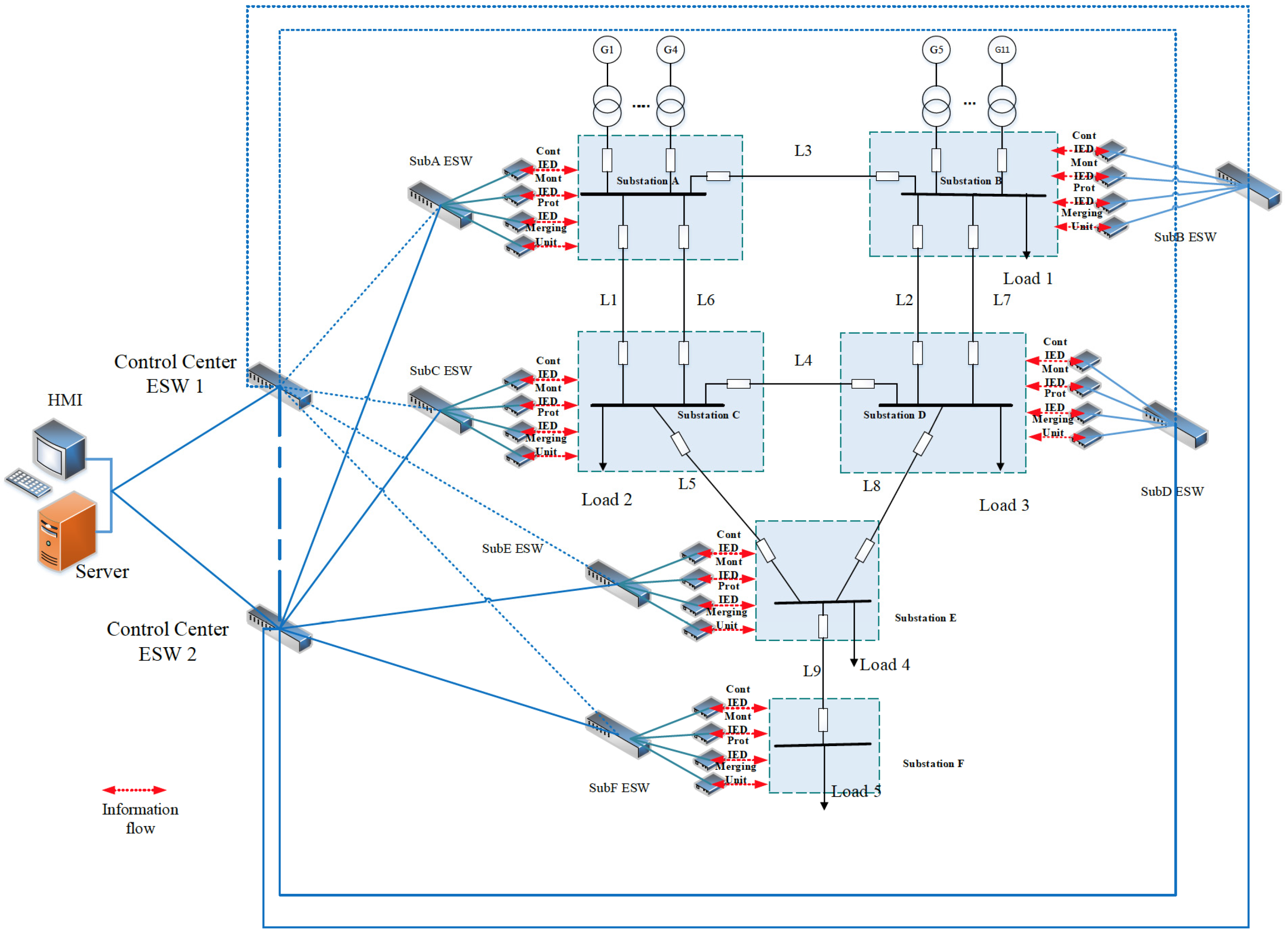
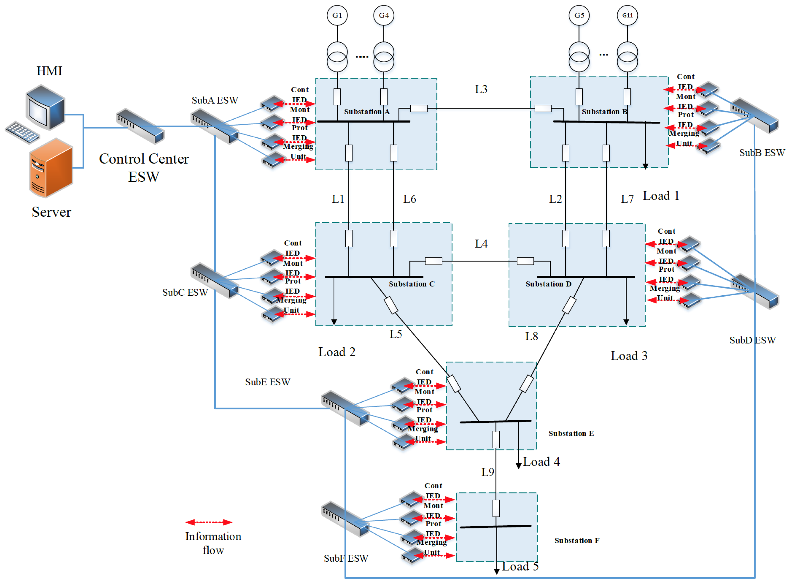
The proposed technique is applied to the 6-substation BRTS. To analyze the impacts of the cyber layer availability and its function failures on the reliability indices of composite power systems, two cyber layer topologies, the cascading topology and the star-ring topology, are illustrated in detail. The CPES models of RBTS with the cyber layer of the cascading topology and the star-ring topology are shown in Figure 11 and Figure 12, respectively.
Figure 11. 
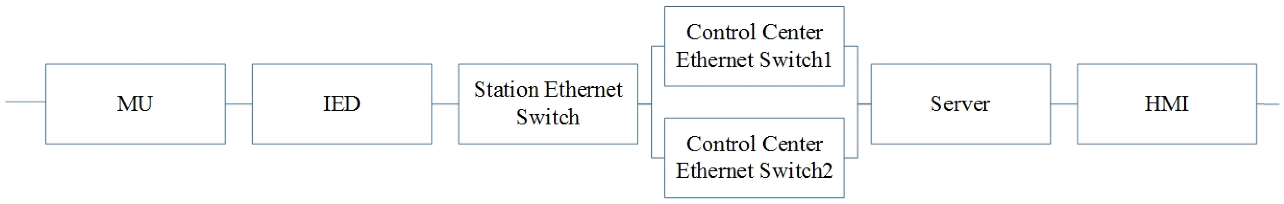
The CPES model of RBTS with the cyber layer of cascading topology.
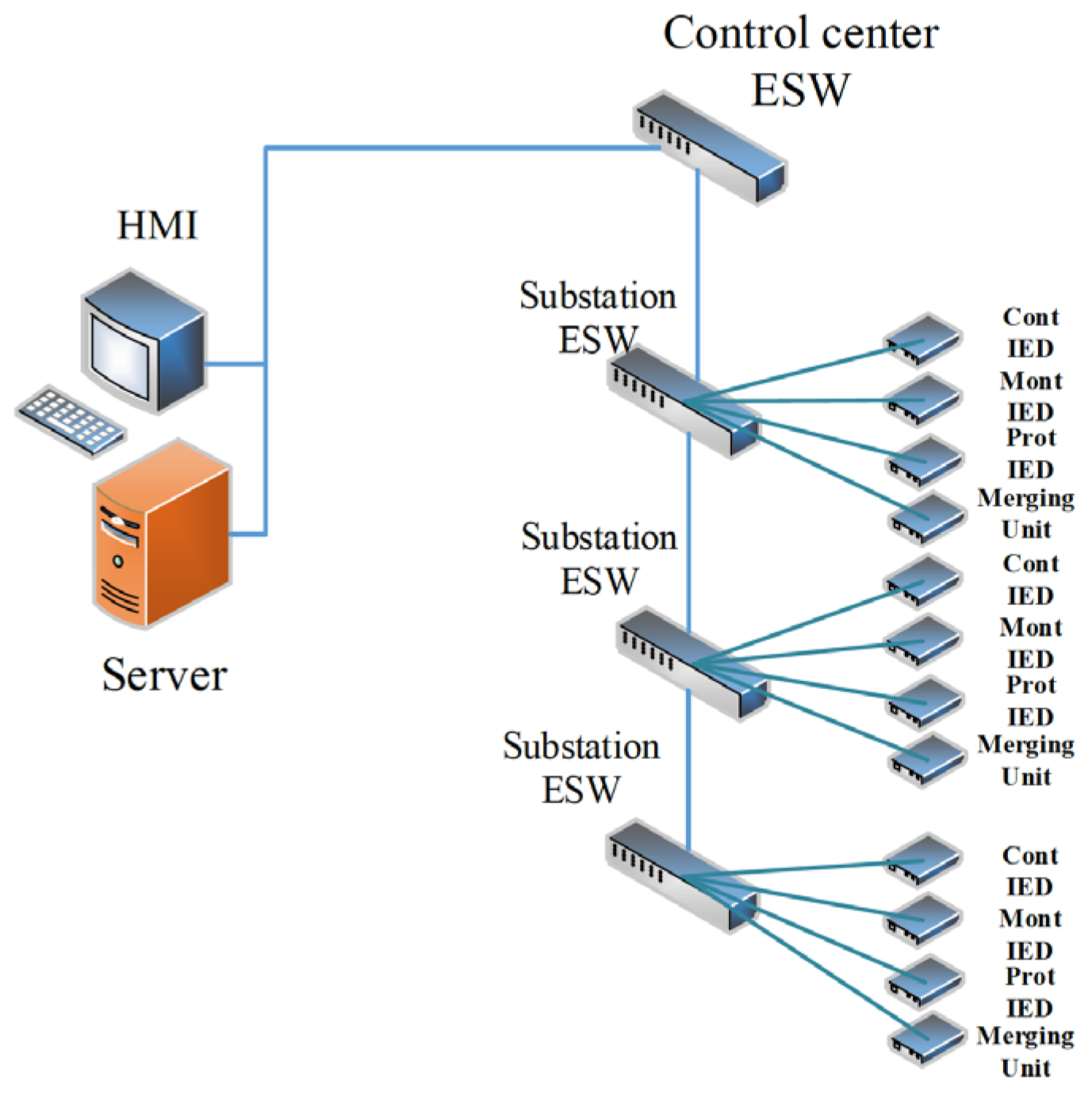
Energies 08 09064 g011
Figure 12. 
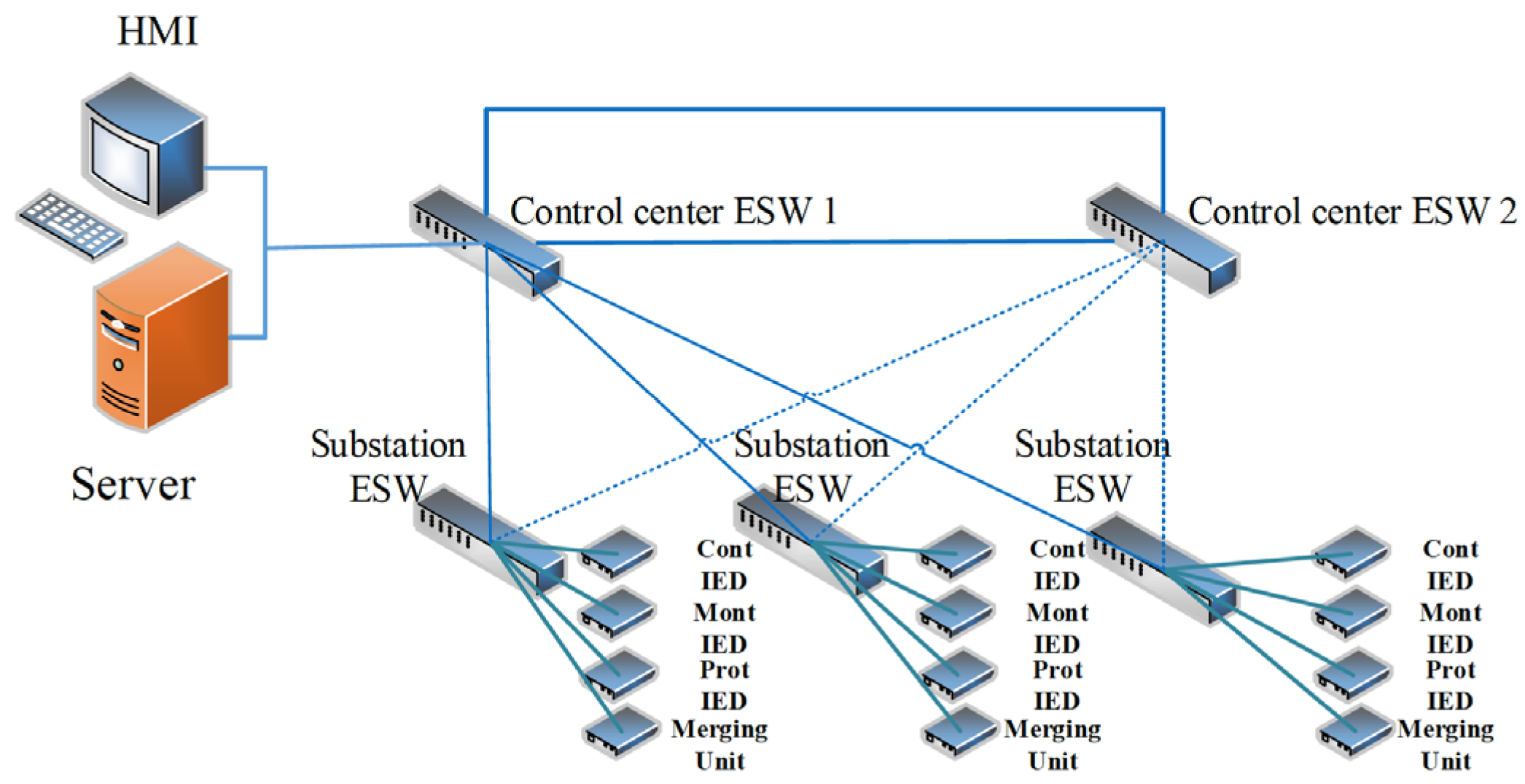
The CPES model of RBTS with the cyber layer of star-ring topology.
Energies 08 09064 g012
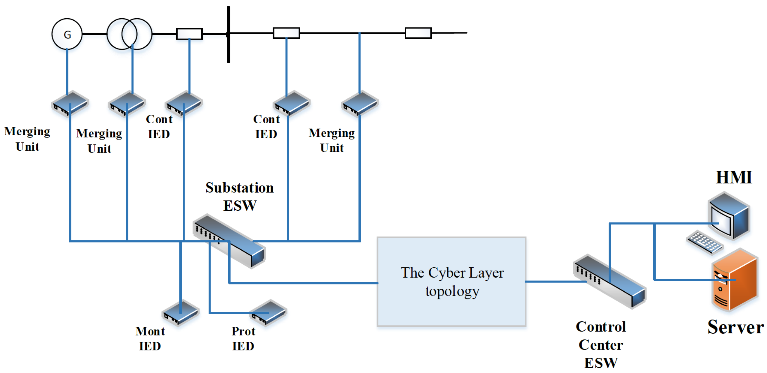
For simplicity, the control center is in charge of those six substations and generating units connected to substations A and B, also the server and the HMI with the highest authority are located in the control center. Within each substation, the connection of the cyber layer is illustrated in a compact form as the above Figure 11 and Figure 12, in which the Control IED, Monitoring IED, Protection IED and Merging unit are represented by one of each kind of the cyber layer components in the substation. The detailed connection and location of them within the substation is as the description in Section 2.2. The optical fiber used as the connection medium is considered fully reliable [23]. The MTTF and MTTR of the cyber layer components are shown in Table 1.
Table 1. The MTTF and MTTR of cyber layer components.
Cyber Layer ComponentMTTF (h)MTTR (h)
Substation Ethernet switch17520072
Control center Ethernet switch17520072
Pro IED17520072
Mont IED17520072
Cont IED17520072
Merging Unit17520072
Server17520072
HMI8760072
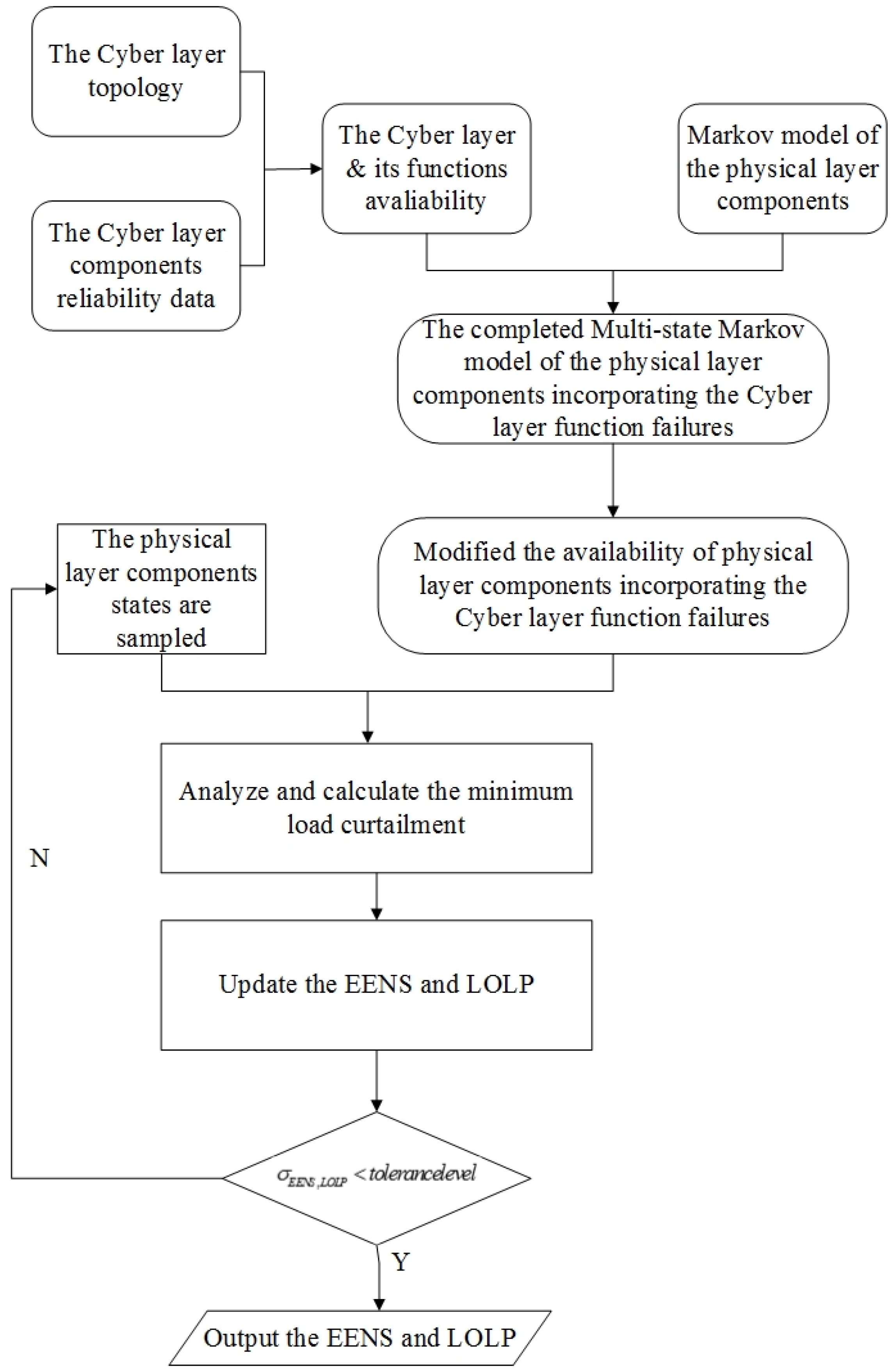
Based on Equations (1)–(11) in Section 2, the MTTF and availability of the cyber layer and its functions are calculated and compared in Table 2.
Table 2. The MTTF and availability of the cyber layer functions.
The Reliability Data of Cyber Layer FunctionCascading TopologyStar-ring Topology
The MTTF of monitoring function 14600h35034h
The availability of monitoring function0.99510.9975
The MTTF of protection function14600h35034h
The availability of protection function0.99510.9975
It can be observed that the availability of the cyber layer protection and monitoring functions are the same for each kind of the topology. The availability of the cascading cyber layer functions is slightly less than that of the star-ring cyber layer functions. However, the MTTF of the cascading cyber layer functions is obviously smaller, which means that the failure rates of the cyber layer functions with the cascading topology are nearly twice of those with the star-ring topology.
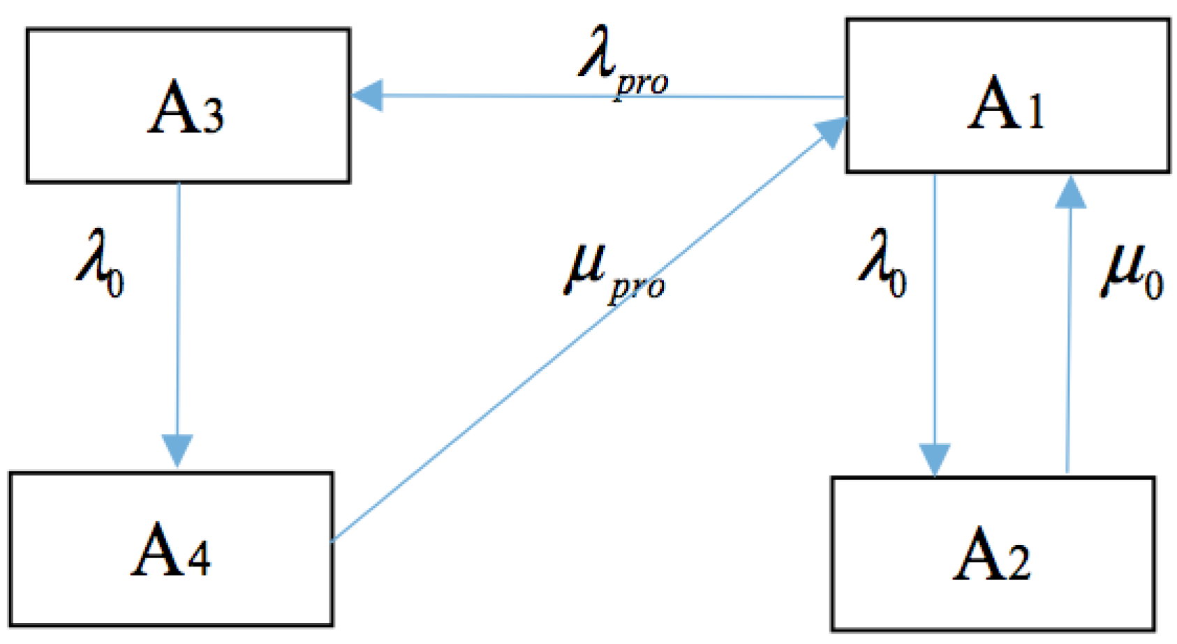
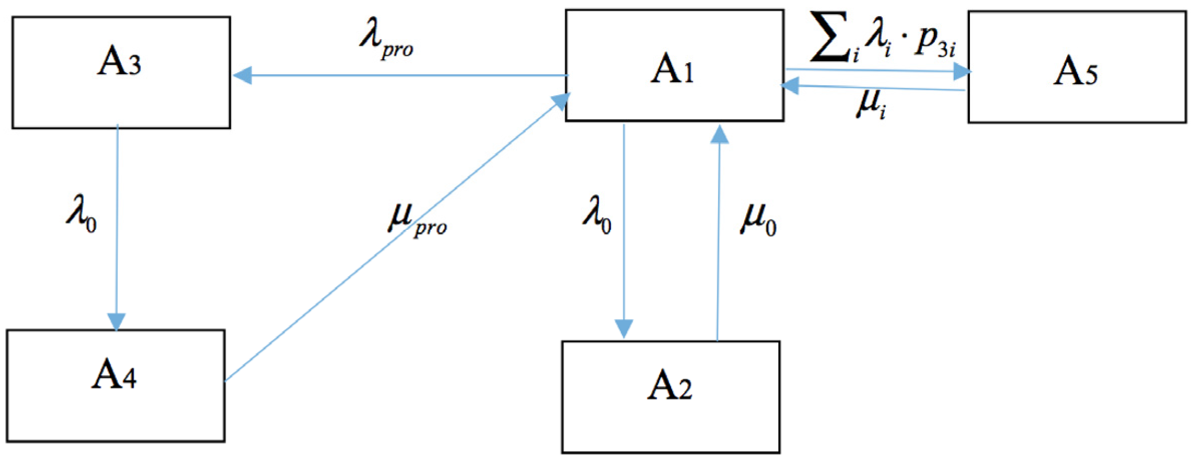
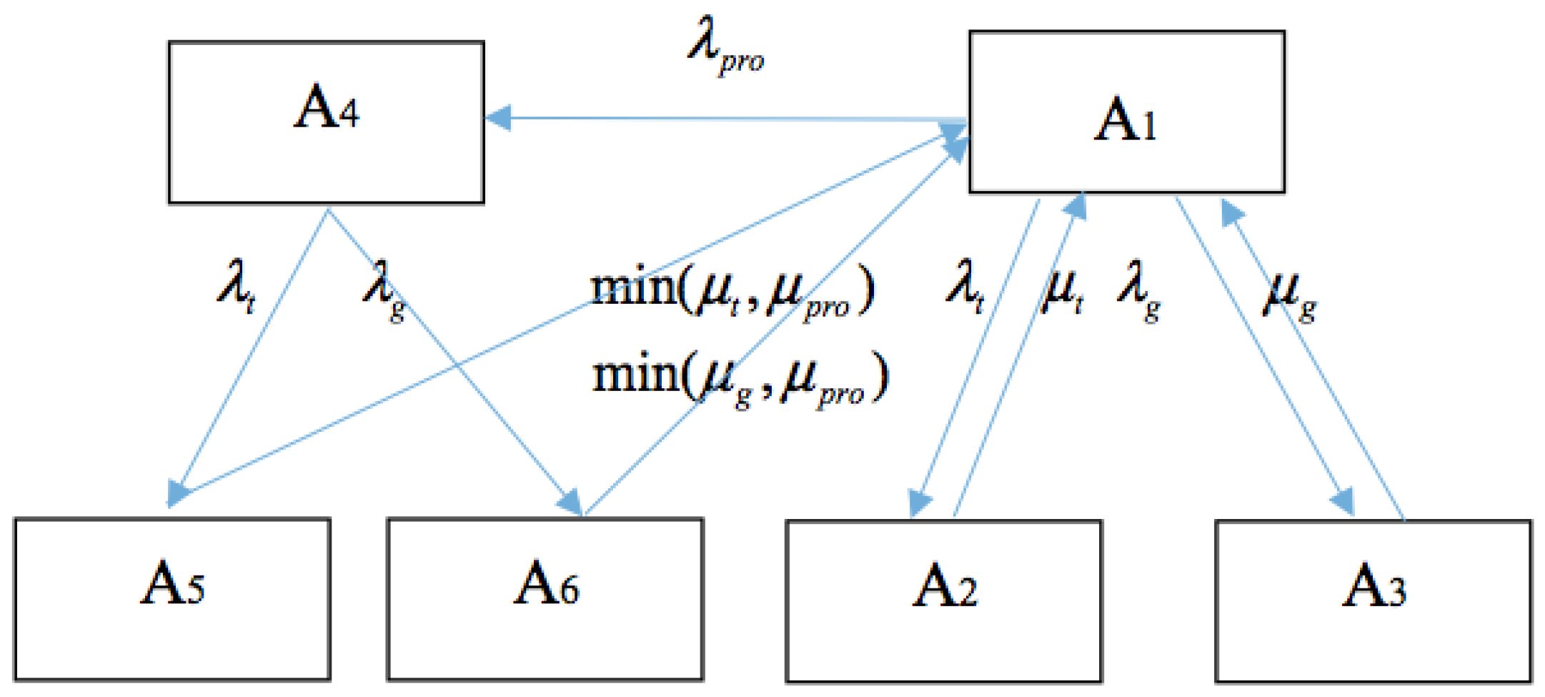
The availability of transmission lines and generating units incorporating the impacts of the cyber layer function failures can be derived, according to the multi-state Markov chain model illustrated in Section 3. The initial availability of transmission lines is taken from [26] and as shown in Table 3.
Table 3. The availability of transmission lines incorporating the protection function failures.
Transmission LineAvailability without the Cyber Layer Availability Incorporating the Protection Function Failures of the Cascading Cyber LayerAvailability Incorporating the Protection Function Failures of the Star-ring Cyber Layer
L10.99830.99460.9960
L20.99430.98970.9918
L30.99550.99090.9929
L40.99890.99530.9964
L50.99890.99550.9967
L60.99830.99460.9960
L70.99440.98970.9918
L80.99890.99540.9966
L90.99890.99590.9969
It can be found that when the cyber layer protection function failures are taken into consideration, the availability of each line decreases. The decrease rate of availability with the cascading cyber layer is about twice of that with the star-ring cyber layer. For lines with the same initial availability, as L1 and L6, the decrease rates are still distinct because the protection of each line acts as the backup protection for different number of adjacent lines and the failure rates of the adjacent lines are different.
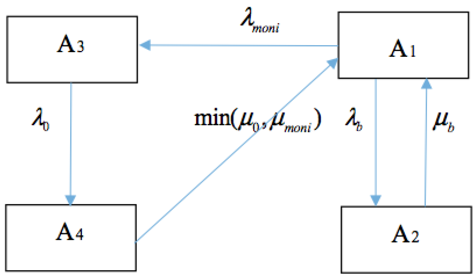
The cyber layer monitoring function is mainly applied to circuit breakers and transformers. The initial availability of circuit breakers and transformers is taken according to [20,26]. Table 4 shows the availability of circuit breakers and transformers with fully available cyber layer monitoring function and monitoring function with failures, respectively.
Table 4. The availability of circuit breakers and transformers incorporating the monitoring function.
Cascading Cyber LayerAvailability without the Cyber LayerAvailability with Fully Available Monitoring FunctionAvailability with the Monitoring Function with Failures
Circuit breaker0.99930.99980.9993
Transformer0.99820.99940.9982
Star-ring cyber layerAvailability without the cyber layerAvailability with fully available monitoring functionAvailability with the monitoring function with failures
Circuit breaker0.99930.99980.9994
Transformer0.99820.99940.9983
It can be observed that when the monitoring function is applied, the availability of each monitored device increases, especially that of transformers. If the monitoring function is not fully available, the increase rate will be less, which is relevant to the availability of the cyber layer monitoring function. After the modified availability of circuit breakers and transformers is obtained and the initial availability of generators is taken according to [26], the availability of generating units with the cyber layer function failures is shown in Table 5 and Table 6, respectively.
Table 5. The availability of generating units incorporating the cascading cyber layer function failures.
Generating Unit Availability without the Cyber LayerAvailability with the Cyber Layer Function Failures
Generating Unit 10.96830.9667
Generating Unit 20.96830.9667
Generating Unit 30.97830.9767
Generating Unit 40.97330.9718
Generating Unit 50.98830.9869
Generating Unit 60.98830.9868
Generating Unit 70.97830.9776
Generating Unit 80.98330.9824
Generating Unit 90.98330.9824
Generating Unit 100.98330.9824
Generating Unit 110.98330.9824
Table 6. The availability of generating units incorporating the star-ring cyber layer function failures.
Generating Unit Availability without the Cyber LayerAvailability with the Cyber Layer Function Failures
Generating Unit 10.96830.9673
Generating Unit 20.96830.9673
Generating Unit 30.97830.9773
Generating Unit 40.97330.9723
Generating Unit 50.98830.9872
Generating Unit 60.98830.9872
Generating Unit 70.97830.9776
Generating Unit 80.98330.9825
Generating Unit 90.98330.9825
Generating Unit 100.98330.9825
Generating Unit 110.98330.9825
The availability of the generating unit with the cyber layer protection and monitoring function failures becomes less when the failures of the cyber layer function is considered, and the availability of each generating unit with the cascading cyber layer is less than that with the star-ring cyber layer. Therefore the cyber layer topology, the availability of the cyber layer functions and the initial reliability of each generator and transformer are the three main factors influencing the availability of generating units in the CPES.

5.2. The Results of Reliability Evaluation

To analyze the impacts of the cyber layer protection and monitoring function failures on composite power systems reliability evaluation, several case studies for comparison have been done. The general description of these case studies is as follows:
  • Case 1: Conventional reliability evaluation of composite power systems without the cyber layer.
  • Case 2: The reliability evaluation when the cyber layer functions of monitoring and protection are fully available.
  • Case 3: The reliability evaluation when the cyber layer monitoring function failures are considered.
  • Case 4: The reliability evaluation when the cyber layer protection function failures are considered.
  • Case 5: The reliability evaluation when both the cyber layer protection and monitoring function failures are considered simultaneously.
The EENS and LOLP are chosen as the reliability indices. Table 7 lists the reliability evaluation results of these five cases with the cascading and the star-ring cyber layer topologies, respectively.
Table 7. The reliability indices of case studies.
Cyber Layer TopologyCascading TopologyStar-ring Topology
Reliability indexEENS (MWh/yr)LOLPEENS (MWh/yr)LOLP
Case 14693.60.09364693.60.0937
Case 23937.50.08383937.50.0837
Case 34654.40.09244614.20.0920
Case 47136.40.11816179.40.1085
Case 56789.90.11525876.70.1050
Based on the results, it is observed that:
(1)
The fully reliable cyber layer monitoring function can decrease the EENS and the LOLP of conventional reliability evaluation by 16.11% and 11.91% because of the availability improvement of transformers and circuit breakers. When the monitoring function is not fully available, the EENS and LOLP decrease less, just 0.84% and 1.39% for the cascading cyber layer, 1.72% and 1.83% for the star-ring cyber layer, respectively. As stated in Section 4, the decrease of EENS and LOLP means the increase of reliability of composite power systems. Therefore it is meaningful to apply highly reliable cyber layer monitoring function to monitor critical electrical components.
(2)
Composite power systems reliability degrades in the case of cyber layer protection function failures, which is indicated by the increase of EENS and LOLP. It is because protection function failures increase the unavailability of transmission lines and generating units.
(3)
The reliability of the composite power system degrades in Case 5 as the EENS and the LOLP increase by 44.66% and 22.83% for the cascading cyber layer, by 25.21% and 12.06% for the star-ring cyber layer, respectively. The availability of the cyber layer functions is inversely related to the downgrade of composite power systems reliability. However, the decrease rate of the cyber layer availability is not linearly dependent on the increase rate of EENS and LOLP because of the non-linearity in the process of state sampling and minimum load curtailment computation.

6. Sensitivity Analysis

To fully illustrate the impacts of cyber layer components and function availability on the reliability indices of composite power systems, it is important to determine the sensitivity of the reliability evaluation indices versus the variation of the cyber layer availability. The following sensitivity analysis is implemented in two parts:
A) As shown in Equations (3), (4), (10) and (11) the relationship between the availability of the cyber layer and that of cyber layer components is linear, except that with Ethernet switches. The linear relationship indicates that the sensitivity of the cyber layer availability versus the availability of cyber layer components is a constant. Therefore, to analyze the impacts of varying availability of cyber layer components on the cyber layer functions’ availability and identify critical cyber layer parts, Ethernet switches should be studied. The varying of the cyber layer availability versus that of Ethernet switches ranging from 0 to 1 is shown in Figure 13.
Figure 13. The sensitivity of Ethernet switches availability versus cyber layer availability.
Energies 08 09064 g013
The figure shows that the cyber layer topology plays an important role in determining the relationship between the availability of the cyber layer and that of Ethernet switches. The availability of the star-ring topology is always more than that of the cascading topology. When the availability of Ethernet switches is in the range from 0.9 to 1, the availability of the cyber layer versus that of Ethernet switches is more sensitive for both cyber layer topologies. So improve the availability of Ethernet switches play an important role in the improvement of cyber layer availability.
B) To analyze the impacts of cyber layer function availability on reliability indices of composite power systems, Cases 3, 4 and 5 are simulated and compared, with the availability of the cyber layer functions ranging from 0.8 to 1. The definitions of Cases 3, 4 and 5 are the same as those descriptions in Section 5. The simulated results are shown in Figure 14.
Figure 14. The sensitivity of reliability indices (a) versus the availability of cyber layer functions (b).
Energies 08 09064 g014
The results show that the monitoring function failures has relatively less effect on composite power systems reliability, as the curves of EENS and LOLP of Case 3 are nearly flat with varying of the cyber layer availability. However, the protection function failures cause a notable threat to the reliability of composite power systems, since even a tiny change of the cyber layer protection function availability causes a significant downgrade of composite power systems reliability, especially in the range from 0.95 to 1.

7. Conclusions

It is necessary to analyze the impacts of the failures of cyber layer functions on composite power system reliability, due to the integration and interdependence of the cyber layer with the physical layer, as well as the uncertainty of the cyber layer in the CPES. This paper proposes a novel approach to analyze the impacts of the cyber layer function failures on the reliability of composite power systems in the background of the CPES. The reliability of the cyber layer with various topologies is calculated with the reliability block diagram method, and then the impacts of the cyber layer function failures on the availability of the physical layer components are modeled via the multi-state Markov chain model. After obtaining the modified reliability and availability of components, composite power systems reliability indices are evaluated through non-sequential Mont-Carlo simulation.
The numerical case studies of the proposed reliability evaluation framework are demonstrated with the RBTS with the cascading and star-ring cyber layer topologies. The results demonstrate that there is a significant improvement in composite system reliability with the application of the cyber layer monitoring function. However, the reliability will downgrade if the cyber layer monitoring and protection function failures are considered, especially the latter ones are considered. Furthermore, various cyber layer topologies and varying cyber layer function availability lead to noteworthy different reliability evaluation results. For specific, the reliability indices of composite power systems are sensitive to the varying availability of cyber layer functions in the range from 0.95 to 1. The cyber layer topology with its functions and actual protection and monitoring strategies of physical components are considered simultaneously to obtain the actual reliability level of composite power systems. The method proposed is a valid reliability evaluation approach to analyze the impacts of the cyber layer function failures on the reliability of composite power systems.

Acknowledgments

The work of Yuqi Han, Yunfeng Wen and Chuangxin Guo was supported in part by the State Key Development Program for Basic Research of China (2013CB228206) and in part by the National Natural Science Foundation of China (51177143).

Author Contributions

Yuqi Han performed the experiments and wrote the paper, Chuangxin Guo conceived the project, Yunfeng Wen and Han Huang reviewed and edited the manuscript. All authors read and approved the manuscript.

Conflicts of Interest

The authors declare no conflict of interest.

References

  1. Farhangi, H. The path of the smart grid. IEEE Power Energ. Mag. 2010, 8, 18–28. [Google Scholar] [CrossRef]
  2. Li, G.; Du, C.; Song, C.; Cai, X. Cyber-physical aware model based on IEC 61850 for advanced power grid. In Proceedings of the Power and Energy Engineering Conference (APPEEC), Chengdu, China, 28–31 March 2010; pp. 1–5.
  3. Rinaldi, S.M.; Peerenboom, J.P.; Kelly, T.K. Identifying, understanding, and analyzing critical infrastructure interdependencies. Control Syst. IEEE 2001, 21, 11–25. [Google Scholar] [CrossRef]
  4. Singh, C.; Sprintson, A. Reliability assurance of cyber-physical power systems. In Proceedings of the Power and Energy Society General Meeting, Minneapolis, MN, USA, 25–29 July 2010; pp. 1–6.
  5. Fu, Y.; Falahati, B. A study on interdependencies of cyber-power networks in smart grid applications. In Proceedings of the IEEE PES Innovative Smart Grid Technologies, Washington, DC, USA, 16–20 January 2012; pp. 1–8.
  6. Falahati, B.; Fu, Y.; Wu, L. Reliability assessment of smart grid considering direct cyber-power interdependencies. IEEE Trans. Smart Gird 2012, 3, 1515–1524. [Google Scholar] [CrossRef]
  7. Falahati, B.; Fu, Y. Reliability assessment of smart grids considering indirect cyber-power interdependencies. IEEE Trans. Smart Gird 2014, 5, 1677–1685. [Google Scholar] [CrossRef]
  8. Singh, C.; Patton, A.D. Models and concepts for power system reliability evaluation including protection-system failures. Int. J. Electr. Power Energy Syst. 1980, 2, 161–168. [Google Scholar] [CrossRef]
  9. Singh, C.; Patton, A.D. Protection system reliability modeling: Unreadiness probability and mean duration of undetected faults. IEEE Trans. Reliab. 1980, 29, 339–340. [Google Scholar] [CrossRef]
  10. Bozchalui, M.C.; Sanaye-Pasand, M.; Fotuhi-Firuzabad, M. Composite system reliability evaluation incorporating protection system failures. In Proceedings of the Conference on Electrical & Computer Engineering, Saskatoon, SK, Canada, 1–4 May 2005; pp. 486–489.
  11. Yu, X.; Singh, C. Power system reliability analysis considering protection failures. In Proceedings of the IEEE Power Engineering Society Summer Meeting, PESS, Chicago, IL, USA, 25–25 July 2002; pp. 963–968.
  12. Xu, X. A practical approach for integrated power system vulnerability analysis with protection failures. IEEE Trans. Power Syst. 2004, 19, 1811–1820. [Google Scholar]
  13. Yang, F.; Meliopoulos, A.P.S.; Cokkinides, G.J.; Binh Dam, Q. Bulk power system reliability assessment considering protection system hidden failures. In Proceedings of the 2007 iREP Symposium—Bulk Power System Dynamics and Control-VII Revitalizing Operational Reliability, Charleston, SC, USA, 19–24 August 2007; pp. 1–8.
  14. Jiang, K.; Singh, C. The concept of power unit zone in power system reliability evaluation including protection system failures. In Proceedings of the Power Systems Conference & Exposition, PSCE, Seattle, WA, USA, 15–18 March 2009; pp. 1–10.
  15. Jiang, K.; Singh, C. New models and concepts for power system reliability evaluation including protection system failures. IEEE Trans. Power Syst. 2011, 26, 1845–1855. [Google Scholar] [CrossRef]
  16. Han, Y.; Song, Y.H. Condition monitoring techniques for electrical equipment: A literature survey. IEEE Power Eng. Rev. 2003, 18, 4–13. [Google Scholar] [CrossRef]
  17. Bourgault, A. Sturdy but sensitive to heat: The impacts of a winding temperature on power transformer reliability. IEEE Power Energy Mag. 2005, 3, 42–47. [Google Scholar] [CrossRef]
  18. Janssen, A.L. CIGRE WG 13.06 studies on the reliability of single pressure SF6-gas high-voltage circuit-breakers. IEEE Trans. Power Deliv. 1996, 11, 274–282. [Google Scholar] [CrossRef]
  19. Zhong, J.; Li, W.; Billinton, R.; Yu, J. Incorporating a condition monitoring based aging failures model of a circuit breaker in substation reliability assessment. IEEE Trans. Power Syst. 2015, 30, 1–9. [Google Scholar] [CrossRef]
  20. Falahati, B.; Fu, Y.; Mousavi, M.J. Reliability modeling and evaluation of power systems with smart monitoring. IEEE Trans. Smart Grid 2013, 4, 1087–1095. [Google Scholar] [CrossRef]
  21. Mackiewicz, R.E. Overview of IEC 61850 and Benefits. In Proceedings of the Power Systems Conference & Exposition, Dallas, TX, USA, 21–24 May 2006; pp. 623–630.
  22. Kanabar, M.G.; Sidhu, T.S. Reliability and availability analysis of IEC 61850 based substation communication architectures. In Proceedings of the IEEE Power & Energy Society General Meeting, Calgary, AB, Canada, 26–30 July 2009; pp. 1–8.
  23. Zhang, Y.; Sprintson, A.; Singh, C. An integrative approach to reliability analysis of an IEC 61850 digital substation. In Proceedings of the IEEE Power and Energy Society General Meeting, San Diego, CA, USA, 22–26 July 2012; pp. 1–8.
  24. Falahati, B.; Darabi, Z.; Fu, Y.; Vakilian, M.; Falahati, B.; Darabi, Z. Quantitative modeling and analysis of substation automation systems. In Proceedings of the IEEE PES Transmission & Distribution Conference & Exposition, Orlando, FL, USA, 7–10 May 2012; pp. 1–7.
  25. Li, W. Risk Assessment of Power Systems: Models, Methods, and Applications, 1st ed.; IEEE Press: Piscataway, NJ, USA, 2004; pp. 69–78. [Google Scholar]
  26. Billinton, R.; Kumar, S.; Chowdhury, N.; Chu, K.; Debnath, K.; Goel, L.; Khan, E.; Kos, P.; Nourbakhsh, G.; Oteng-Adjei, J. A Reliability Test system for educational purpose-basic data. IEEE Trans. Power Syst. 1989, 9, 67–68. [Google Scholar]

