Article

CO2 Fixation by Membrane Separated NaCl Electrolysis

1
Department of Chemical and Biomolecular Engineering, Yonsei University, 262 Seongsanno, Seodaemun-gu, Seoul 120-749, Korea
2
Proton Conductors Section, Department of Energy Conversion and Storage, Technical University of Denmark, Kemitorvet 207, Kgs. Lyngby DK-2800, Denmark
3
CO2 Sequestration Department, Korea Institute of Geoscience and Mineral Resources (KIGAM), 124 Gwahak-ro, Yuseong-gu, Daejeon 305-350, Korea
*
Author to whom correspondence should be addressed.
Energies 2015, 8(8), 8704-8715; https://doi.org/10.3390/en8088704
Submission received: 10 June 2015 / Accepted: 10 August 2015 / Published: 14 August 2015

Abstract

:
Atmospheric concentrations of carbon dioxide (CO2), a major cause of global warming, have been rising due to industrial development. Carbon capture and storage (CCS), which is regarded as the most effective way to reduce such atmospheric CO2 concentrations, has several environmental and technical disadvantages. Carbon capture and utilization (CCU), which has been introduced to cover such disadvantages, makes it possible to capture CO2, recycling byproducts as resources. However, CCU also requires large amounts of energy in order to induce reactions. Among existing CCU technologies, the process for converting CO2 into CaCO3 requires high temperature and high pressure as reaction conditions. This study proposes a method to fixate CaCO3 stably by using relatively less energy than existing methods. After forming NaOH absorbent solution through electrolysis of NaCl in seawater, CaCO3 was precipitated at room temperature and pressure. Following the experiment, the resulting product CaCO3 was analyzed with Fourier transform infrared spectroscopy (FT-IR); field emission scanning electron microscopy (FE-SEM) image and X-ray diffraction (XRD) patterns were also analyzed. The results showed that the CaCO3 crystal product was high-purity calcite. The study shows a successful method for fixating CO2 by reducing carbon dioxide released into the atmosphere while forming high-purity CaCO3.

1. Introduction

Increases in energy consumption due to population growth and industrial development have had a large effect on global warming by raising carbon dioxide (CO2) concentrations in the atmosphere [1]. CO2 is one of the six major gases causing global warming (CO2, CH4, N2O, HFCs, PFCs, SF6) [2], accounting for an estimated 80% of the greenhouse gases by amount [3]. For this reason, many researchers have focused on studies to reduce atmospheric concentrations of CO2.
Among the various worldwide attempts to reduce atmospheric CO2 concentrations, carbon capture and storage (CCS) technology, which captures released CO2 and storages underground or underwater, is considered the most effective and efficient technology. In CCS technology, CO2 can be captured before, during, or after coal or gas combustion [4]. CO2 content in flue gas is reduced by physical, chemical, or biological means, and CCS industries, which process CO2 after combustion, use chemical solvents [5,6]. From an energy and climate policy point of view, this type of CCS technology is theoretically the most effective method to reduce amount of CO2 released but also entails the possibility of resistance from the general public due to high investment costs, limitation and uncertainty of potential storage capacity of CO2. According to Nicholas et al. [7], over 80% of energy used in CCS is consumed in the CO2 desorption process. In addition, according to Baciocchi et al. [8], CO2 capture mechanisms require considerable energy and costs. Yu et al. [1] and Gough [9] have noted possible safety problems (due to earthquake or volcanic activity) from long-term CO2 storage, while Holloway [10] reported on its risks, citing the example of a CO2 leak case in Cameroon’s Nyos Lake. Damen et al. [11] reported on five types of risks for underground carbon dioxide storage (CO2 and CH4 leakage, seismicity, ground movement, displacement of brine) [12]. In addition to these problems, according to Mazzoldi et al. [12], there is a possibility of CO2 leakage caused by corrosion or external damage of pipeline of high-pressure transportation system, which was reported in the oil industry literature [13].
Because of these problems, studies related to the carbon capture and utilization (CCU) technology that recycles carbon dioxide as a resource has attracted attention. Existing CCU technologies for the production of calcium carbonate can be divided into direct and indirect reactions between solid chemicals and CO2 gas, and aqueous system methods. Solid calcium carbonate production processes use relatively greater energy than liquid production processes. For example, according to research by Lackner et al. [14], Stasiulaitiene et al. [15] and Fagerlund et al. [16,17,18], the carbonation process for magnesium hydroxide obtained from serpentine requires high temperature (over 500 °C) and high-pressure (over 20 bar) conditions. In contrast, the liquid method according to Gerdemann et al. [19] and Khoo et al. [20] requires relatively lower carbonation temperature and pressure conditions of 185 °C and more than 40 bar, and 170 °C and 1 bar, respectively. However, the method which uses an aqueous system to produce carbonate also requires a reaction condition of high temperature and pressure. As with the solid calcium carbonate production method, it clearly requires great amounts of energy for processes such as cool-down in high-temperature and high-pressure conditions, compared to CCS separation methods [21]. For these reasons, existing methods cannot be considered as optimal alternatives for reducing atmospheric CO2 concentrations. For optimal CO2 reduction, methods that (1) satisfy environmental considerations by addressing possible CO2 leaks, and (2) reduce energy consumption compared to existing carbonation processes conducted at high-temperature and in high-pressure conditions must be devised.
This study proposes a carbonation process which uses relatively less energy than traditional process, through an electrolysis technology using ceramic membrane. CO2 usually reacts with alkaline solutions as absorbent, with NaOH (Sodium Hydroxide) and NH4 (Ammonium) solution, MEA (Mono-ethanol Amine), DEA (Di-ethanol Amine), and MDEA (N-methyl Diethanolamine) being the most common examples [22]. Previous studies use magnesium hydroxide (Mg(OH)2) in order to absorb CO2. Existing processes such as the one by Nduagu et al. [23] require the use of ammonium magnesium salt heated to over 500 °C in order to extract magnesium from serpentine or other magnesium silicates. They also require high temperature reaction conditions for the separation process of magnesium oxide (MgO) and silicon dioxide (SiO2) from serpentine, and the hydration process after separation. Accordingly, this study uses NaOH (Sodium Hydroxide) as absorbent for CO2 through electrolysis of NaCl in seawater. The proposed method enables formation of NaOH using low voltage of 1–4 amperes.
This technology was proven to produce alkaline solution at low voltages by CALERA Corporation of the US [24]. Furthermore, the electrolysis process using a ceramic membrane requires no additional pressure or temperature. Additionally, the carbonation process does not require a separate process for the separation of the absorbed CO2. This enables it to reduce energy consumed in the process of CO2 desorption, and to significantly reduce energy consumption through reaction at room pressure and room temperature. Moreover, the chemical conversion solution produced after the carbonation reaction can be recycled as feed solution for the electrolysis to produce NaOH. Accordingly, this study may find its significance in overcoming the problems of existing CO2 reduction technologies (CCS and CCU technology) by stably fixating CO2 at room temperature and room pressure with relatively less energy, while producing a metal carbonate to generate income.

2. Experimental Section

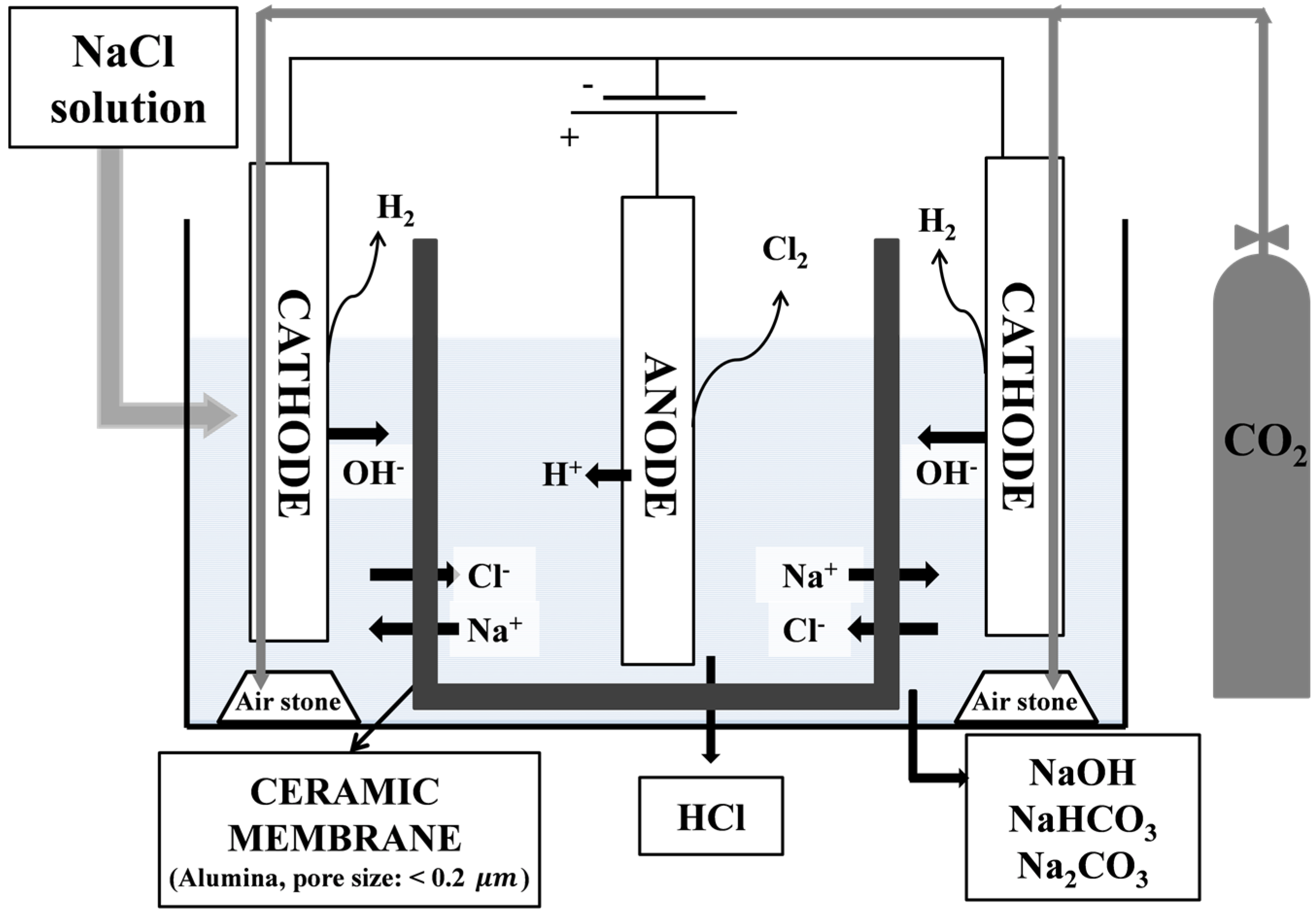
2.1. Materials and Electrolysis Device

Sodium chloride (NaCl), 99.5% (Mn = 58.43 g/mol) used as feed for electrolytic reaction was purchased from Samchun chemical (Gyeonggi-do, Korea). Calcium chloride (CaCl2), 95.9% (Mn = 110.98 g/mol) was purchased from Kanto (Tokyo, Japan) to produce the carbonate, carbon dioxide (CO2) gas was purchased from Samheung (Gyeonggi-do, Korea). Calcium carbonate (CaCO3), ≥99.0% (Mn = 100.09 g/mol) used to determine formation of final product purity of CaCO3 was purchased from Sigma-Aldrich (St Louis, MO, USA), and de-ionized water was used as solvent in the experiment.
Figure 1 is a schematic diagram of the electrolysis device designed for the experiments. The device was built with 10 mm acrylic material. In general, ion-exchanged membrane or ceramic membrane is used for electrolysis device. Ferro et al. [25] reported that an ion-conducting ceramic membrane around the graphite anode is necessary in electrolytic cells where reactive metals, such as calcium, magnesium and sodium, are produced to minimize the possibility of back reactions. Therefore, in this study ceramic membrane (Korea Material scientific, Changwon, Korea) which has less than 0.2 μm pore size of alumina material, was used. The ceramic membrane used in this experiment has excellent physical properties and can be used semi-permanently, compared with MF membrane. Electrolytes in the acrylic water tank are divided into cathodes and anodes by a ceramic membrane, a negative electrode was used as the stainless steel, a positive electrode was used as the graphite. To increase the contact area between CO2 bubbles and absorbent produced by electrolysis, a high-pressure air stone (DAE Yang Air Stone Ind., Co, Busan, Korea) was used, which generates fine CO2 bubbles.
Figure 1. Schematic diagrams of the electrolysis device for the electrolysis of NaCl solutions.
Energies 08 08704 g001

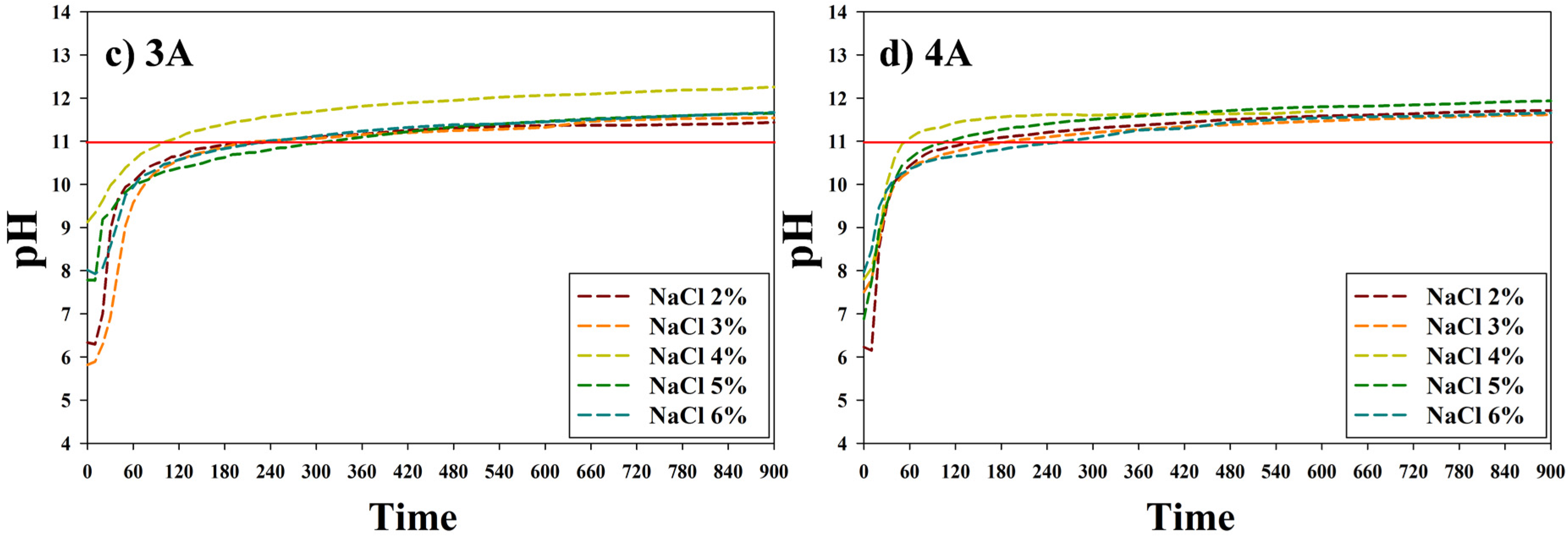
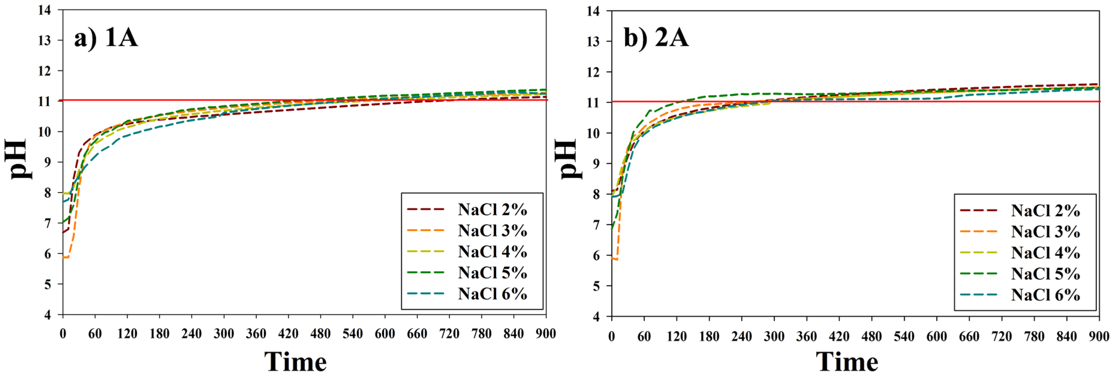
2.2. Electrolysis of NaCl Solution

The method used in this study is based on chemical absorption and conversion method in CCS technology. Among the alkali solutions used as CO2 absorbents, amine-family absorbents were excluded due to toxicity, while magnesium hydroxide (Mg(OH)2) used in existing processes was excluded due to high temperature and high pressure reaction conditions. For these reasons, NaOH, which does not require high temperature and high pressure reaction conditions, was obtained through electrolysis of seawater and used as an absorbent. In the case of the NaCl solution used as feed for electrolysis, various concentration ranges were used based on concentrations (NaCl 2%–6%, 5L volume) in seawater and seawater concentrate. The NaCl solutions were prepared in the electrolysis device as in Figure 1, changes in pH over time were checked using pH electrodes (ORION 3-STAR Benchtop pH/ISE meter, Thermo Scientific Korea, Seoul, Korea), and the electrolysis was conducted using even an current of 1–4 amperes. Electrolysis was conducted for 10–15 min at a temperature of around 25 °C and atmospheric pressure, and the underlying reaction is as follows:
2Cl → Cl2 + 2e (anode, oxidation reaction)
2H2O + 2e → H2 + 2OH (cathode, reduction reaction)
2NaCl + 2H2O → 2NaOH + H2 + Cl2

2.3. CO2 Gas Capture Using Sodium Hydroxide

NaOH is produced at the “negative” electrode as CO2 absorbent. CO2 gas was injected at an even flow rate into the NaOH feed solution through the CO2 generator. The weak acidic CO2 gas combined with alkaline NaOH to form the intermediate compound of sodium bicarbonate (NaHCO3) form needed for the generation of calcium carbonate (CaCO3). This is represented by the following neutralizing reaction:
NaOH + CO2 → NaHCO3

2.4. Precipitation of CaCO3 by the Titration

CaCO3 was generated through precipitation by adding CaCl2 feed solution to sodium bicarbonate (NaHCO3) produced in this study.
According to Henry’s law and the solubility constant, the pH value affects the distribution of ionic CO2; in order to increase the conversion rate to CaCO3, bicarbonate should be turned into carbonate by adjusting pH level. Figure 2 shows changes of carbonic acid (H2CO3), bicarbonate (HCO3), and carbonate (CO32−) compositions in accordance with pH at 25 °C. Sodium bicarbonate (NaHCO3) is converted into sodium carbonate (Na2CO3) when pH level is higher than 12. Converted Na2CO3 is precipitated as CaCO3 by adding CaCl2 solution. The reaction by which the highly reactive Ca2+ and Na+ form CaCO3 through substitution reaction is as follows:
Na2CO3 + CaCl2 → 2NaCl + CaCO3
Figure 2. Carbonate-bicarbonate speciation in water v. pH at 25 °C (Reproduced with permission from [26]. Copyright 2012, John Wiley & Sons).
Energies 08 08704 g002
Reaction was conducted by the titration method, and the Ca2+ ion selective electrode (orion ionplus calcium electrode, Thermo Scientific Orion, Beverly, MA, USA) was used in order to confirm the end of the carbonate reaction. Changes in the concentration of the Ca2+ ion selective electrode were observed by adding CaCl2 solution in prepared concentrations. CaCl2 feed solution added by the titration method is fully consumed through substitution reaction, so the concentration at the Ca2+ ion selective electrode was close to zero as the reaction was in progress. When the CO32− was fully reacted, Ca2+ ion selective electrode concentration also changed, and the reaction was deemed as completed and terminated. The precipitate after the reaction was filtered using a GF/C film (Whatman® Glass microfiber filters, Whatman, Clifton, NJ, USA). It was dehydrated in a vacuum oven for 24 h at room temperature. After dehydrating, the output was a white powder form.

2.5. Characterization of CaCO3

Fourier transform infrared spectroscopy (Spectrum 100 FT-IR Spectrometer, PerkinElmer, Norwalk, CT, USA) was used to confirm molecular structure of CaCO3, the final product of the experiment. Each sample spectrum was measured in the 4000–600 cm−1 wavenumber ranges after drying for over 24 h in a vacuum oven. The particles of the product in the form of powder was applied on carbon tape, and then coated with platinum for several minutes. Shape and size of the coated particles was confirmed by using field emission scanning electron microscopy (FE-SEM, JEOL-6701F, JEOL, Tokyo, Japan). Measurements of confirmed particles were done through X-ray diffraction (XRD, Ultima IV, RIGAKU, Tokyo, Japan) pattern analysis at 40 kV/30 mA output.

3. Results and Discussion

3.1. The Metal Carbonate Produced by the CO2 Fixation.

In Figure 1, as electrolysis is conducted in the electrolysis device, Na+ and OH ions, and H+ and Cl ions are separated into the “negative” and “positive” electrodes, respectively, to form alkaline NaOH and acidic HCl. Figure 3 shows the changes in pH over time measured with a pH installed in the “negative” electrode. Feed solution of electrolysis using a NaCl solution (2%–6% concentration) of five liters. Figure 3 shows that regardless of concentration, NaCl solution approaches a pH of 12 over time at 1–4 A conditions (8–20 V voltage, approx. 25 °C and atmospheric pressure). The time to end the electrolysis was determined when the pH value was no longer increased. Electrolysis was completed over 10–15 min in all cases, and reaction time decreased as ampere was increased. It was shown that sodium bicarbonate, a CO2 absorbent, could be produced without high temperature, high pressure conditions. The NaOH produced through electrolysis satisfied the reaction conditions through pH control, after which reaction took place over 2–3 h with CaCl2 in feed solution form, representing a substantial reduction in reaction time over naturally-occurring CaCO3 composite reaction.
Figure 3. Result of the electrolysis of NaCl solution. (a) 1A condition; (b) 2A condition; (c) 3A condition; (d) 4A condition.
Energies 08 08704 g003aEnergies 08 08704 g003b

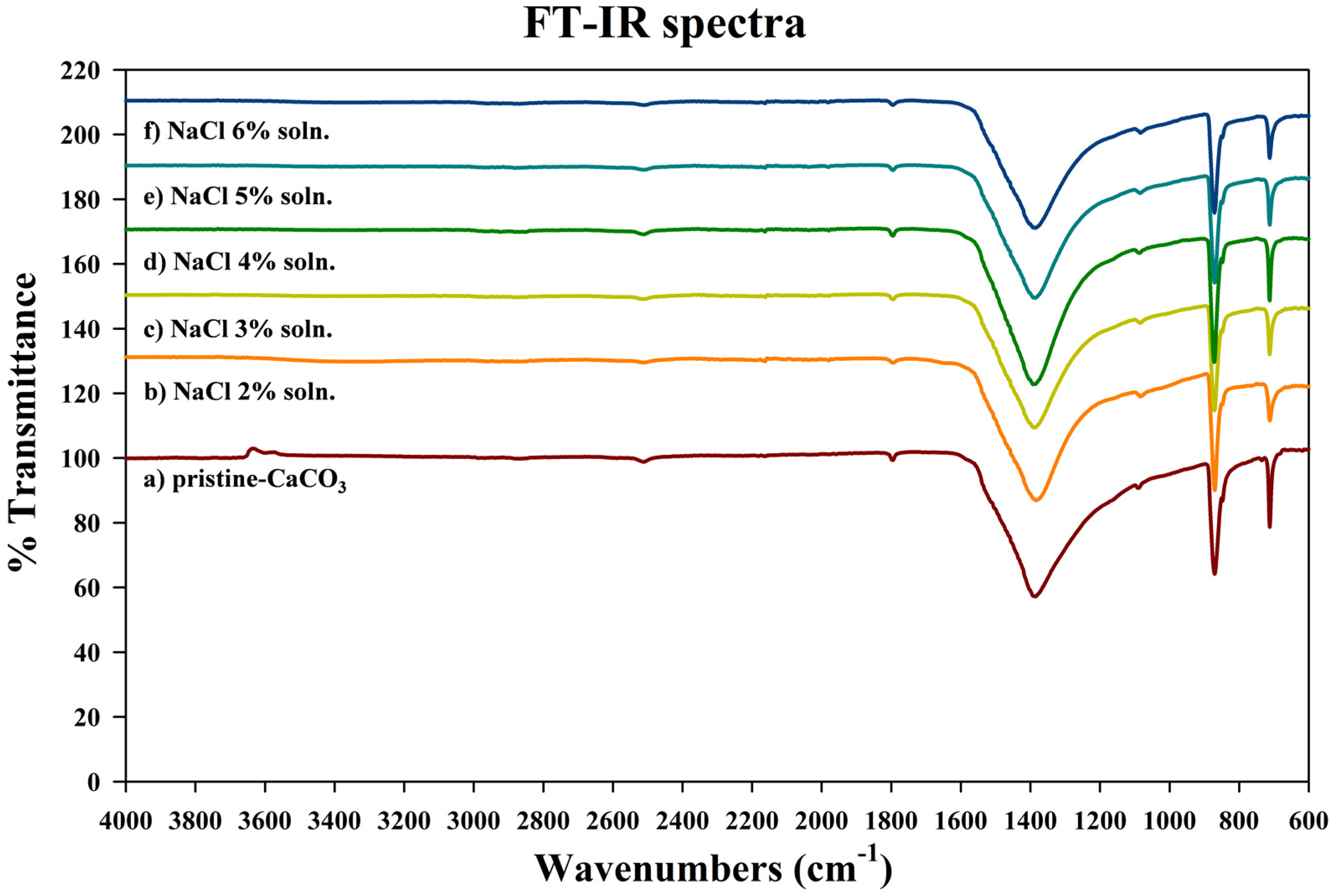
3.2. Characteristics of the Metal Carbonate: FT-IR Analysis

Fourier transform infrared spectroscopy (FT-IR) was used to confirm the molecular structure of the white-powder form precipitate obtained through the experiment. Figure 4 shows a comparison between FT-IR spectra of pristine CaCO3 and those of experiment-derived CaCO3 particles. Figure 4 shows that the characteristic peaks of the pristine CaCO3 and those of experiment-derived CaCO3 particles are consistent. Table 1 shows the FT-IR peak values of CaCO3 particles, which confirms that they are consistent with characteristic peaks values of 1418 cm−1 (C–O function group, stretching mode in calcite), 876 cm−1 (C–O function group, In-plan bending), and 713 cm−1 (C–O function group, Out-plan bending in calcite) for CaCO3 in calcite form. This is also consistent with research by Tlili et al. [27] and Wu et al. [28] on FT-IR spectra for CaCO3.
Figure 4. FT-IR spectrum of (a) pristine-CaCO3; (b) NaCl 2% soln; (c) NaCl 3% soln; (d) NaCl 4% soln; (e) NaCl 5% soln; (f) NaCl 6% soln.
Energies 08 08704 g004
Table 1. Assignment of peaks for CaCO3.
Wavenumber (cm−1)Function GroupsVibration
2513Combination1080 cm−1 and 1440 cm−1
1796Combination1080 cm−1 and 713 cm−1
1418C–OStretching mode (1490 cm−1, 1420 cm−1 in vaterite; 1418 cm−1 in calcite; 1465 cm−1 in aragonite)
1080O–C–OStretching mode
876C–OIn-plane bending
848C–OIn-plane bending (only appeared in vaterite and aragonite)
713C–OOut-plane bending (750 cm−1 in vaterite; 713 cm−1 in calcite; 707 cm−1, 692 cm−1 in aragonite)

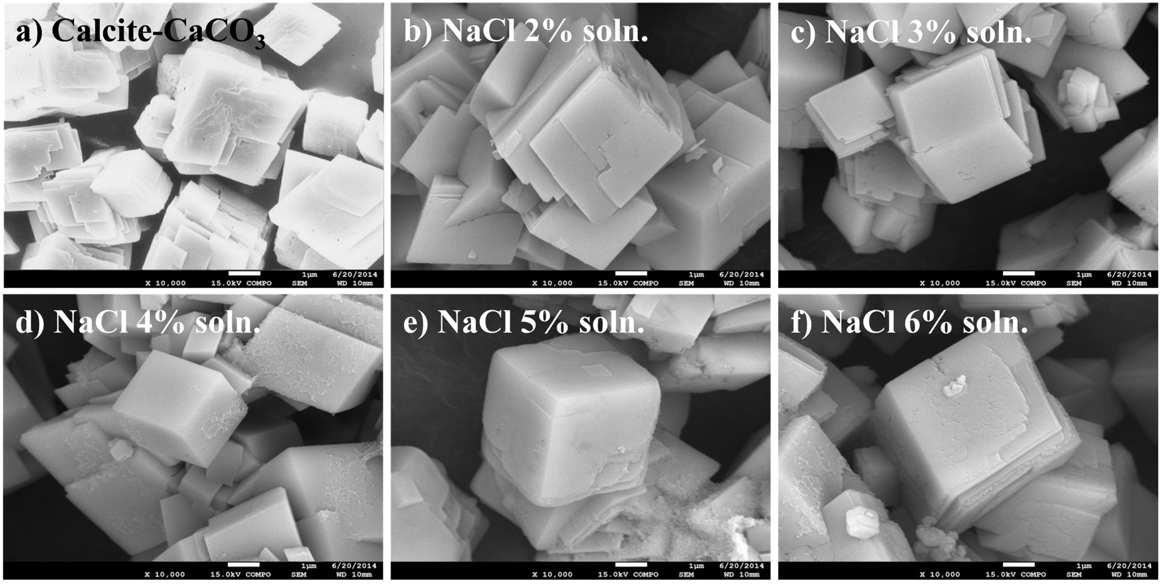
3.3. Characteristics of the Metal Carbonate: FE-SEM Image Analysis

In general, CaCO3 is known to exist in three crystals forms—cubic (calcite), spherical (aragonite), and columnar (vaterite) [29,30,31]. Through comparative analysis with FT-IR spectra of pristine CaCO3, the molecular structure of the precipitate obtained through the experiment was confirmed as being that of calcite. However, when compared with values in Table 1, it was confirmed as having the vibration of CaCO3 in cubic form. Accordingly, field emission scanning electron microscopy (FE-SEM) images were taken in order to get a more clear confirmation of the crystal form. The FE-SEM images in Figure 5 show that the CaCO3 obtained through the experiment were observed to be of cubic form. Other crystal forms of calcite were not identified, and changes in crystal form did not vary with increases in feed solution concentrations.
Figure 5. SEM images of the sample precipitated by the carbonation. (×10,000) (a) Calcite-CaCO3; (b) NaCl 2% soln; (c) NaCl 3% soln; (d) NaCl 4% soln; (e) NaCl 5% soln; (f) NaCl 6% soln.
Energies 08 08704 g005

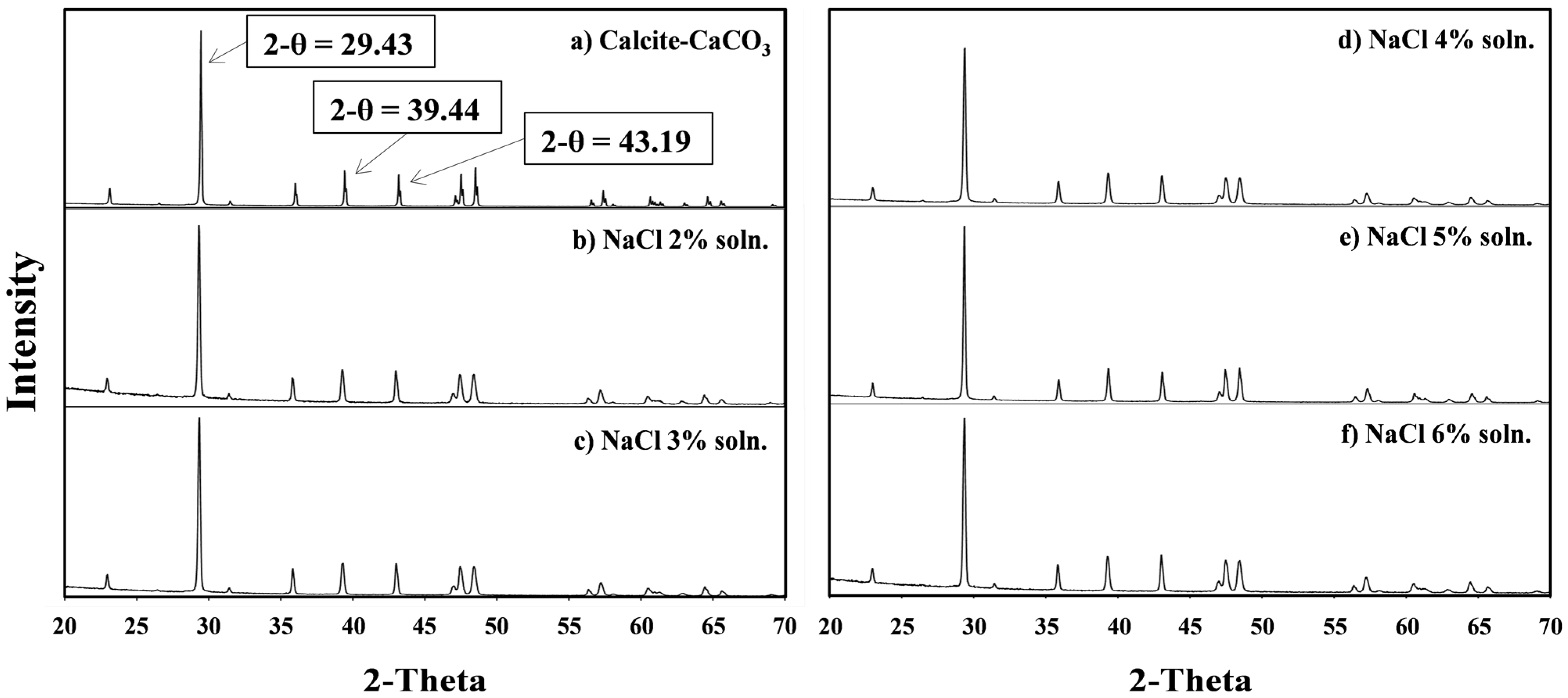
3.4. Characteristics of the Metal Carbonate: The XRD Pattern Analysis

While FT-IR and SEM images confirmed that the precipitate calcite was CaCO3, X-ray diffraction (XRD) pattern analysis was conducted on the precipitate to confirm the crystal structure. Figure 6 shows the XRD patterns of pristine CaCO3 and experiment-derived samples. The XRD patterns of the selected CaCO3 samples display sharp reflection lines between 20° and 70° at the characteristic 2-θ positions. A comparison with the JCPDS values in Figure 6 shows that the 2-θ values of the CaCO3 obtained through the experiment are consistent with the known 2-θ values of calcite of 29.32° (d-value 3.04 Å), 39.34° (d-value 2.29 Å), and 43.08° (d-value 2.10 Å) [32]. No other 2-θ values were detected, other than those for characteristics peaks in calcite form. The XRD pattern analysis shows that the CaCO3 (white-powder form precipitate) obtained through the experiment is calcite of high purity.
Figure 6. XRD patterns of the sample precipitated by the carbonation. (a) Calcite-CaCO3; (b) NaCl 2% soln; (c) NaCl 3% soln; (d) NaCl 4% soln; (e) NaCl 5% soln; (f) NaCl 6% soln.
Energies 08 08704 g006

4. Conclusions

This study proved that CaCO3 could be stably formed by absorbing CO2 at normal room temperature and pressure conditions. Among absorbents used in existing CCS technology, a series of toxic amine was excluded, and a more environment-friendly method for CO2 fixation was realized by using NaOH as absorbent. In addition, an electrolysis method which uses ceramic membrane at 25 °C, and atmospheric conditions with voltage of 8–24 V for 10–15 min, was used for the formation of NaOH. Through this method, NaOH was produced more effectively. In the case of the carbonation process, the precipitate was stably formed through a substitution reaction between Ca2+ and Na+, by adding CaCl2 at room temperature and atmospheric conditions. It was also confirmed as being calcite through FT-IR spectra measurements. Furthermore, the contents of the chemical solvent resulted from CaCO3 precipitate formation consisted of sodium chloride (NaCl) and sodium hydroxide (NaOH), which can be reused as feed solution for electrolysis via an additional concentration process. Through SEM image and XRD pattern analyses, it was revealed that the precipitate CaCO3 powder was high-purity calcite-CaCO3 of cubic crystal form. CaCO3 exists in calcite of cubic form, aragonite of spherical form, and vaterite of columnar form, of which cubic calcite is most stable [33]. Aragonite transforms into calcite at 380–470 °C, and vaterite is the most unstable [34,35].
Natural formation of CaCO3 requires extensive time and entails numerous reciprocal interactions. The method presented not only does not require high temperature reaction conditions but also makes it possible to form CaCO3 in a short time. Moreover, the CaCO3 produced is calcite of high purity which does not require an additional refinement process. According to Siefert and Litster [7], the most of energy used in CCS is consumed in the desorption process. However, the presented method does not use the desorption process, so the energy required to remove CO2 does not need to be considered. According to Svensson et al. [36], in the transport process, in the range from 1 €/ton up to 18 €/ton of CO2, costs arise. However, the presented method does not require a transport process of CO2, so it can reduce the cost as much as 18 €/ton of CO2. In order to overcome disadvantages of existing methods using serpentine or other magnesium silicate at high temperatures (over 500 °C) and high pressure (over 20 bar) conditions to produce Mg(OH)2, the method which uses electrolysis at room temperature and pressure is used to produce absorbent. High temperature (over 500 °C) and high pressure (over 20 bar) conditions incurs costs, so this study provides economic benefits.
As demonstrated through this experiment, this study proposes a more stable carbonation method for more environment-friendly and economical CO2 fixation and recycling of chemical ingredients. On the basis of the aforementioned considerations, we would like to be able to reduce the CO2 emissions through recycling the CO2 with the method that we have proposed.

Acknowledgments

This work was supported by the Human Resources Program in Energy Technology of the Korea Institute of Energy Technology Evaluation and Planning (KETEP), granted financial resource from the Ministry of Trade, Industry & Energy, Republic of Korea. (No. 20154010200810).

Author Contributions

Hyun Sic Park performed the experiments, analyzed the data, and wrote first draft; Ju Sung Lee, JunYoung Han, Sangwon Park analyzed the data; Byoung Ryul Min and Jinwon Park revised the manuscript.

Conflicts of Interest

The authors declare no conflict of interest.

References

  1. Yu, K.M.K.; Curcic, I.; Gabriel, J.; Tsang, S.C.E. Recent advances in CO2 capture and utilization. ChemSusChem 2008, 1, 893–899. [Google Scholar] [CrossRef] [PubMed]
  2. Khoo, H.H.; Tan, R.B. Environmental impact evaluation of conventional fossil fuel production (oil and natural gas) and enhanced resource recovery with potential CO2 sequestration. Energy Fuels 2006, 20, 1914–1924. [Google Scholar] [CrossRef]
  3. West, T.O.; Peña, N. Determining thresholds for mandatory reporting of greenhouse gas emissions. Environ. Sci. Technol. 2003, 37, 1057–1060. [Google Scholar] [CrossRef] [PubMed]
  4. Zeebe, R.E.; Zachos, J.C.; Caldeira, K.; Tyrrell, T. Carbon emissions and acidification. Sci. N. Y. Wash. 2008, 321, 51. [Google Scholar] [CrossRef] [PubMed]
  5. Abbott, T.M.; Buchanan, G.W.; Kruus, P.; Lee, K.C. 13c nuclear magnetic resonance and Raman investigations of aqueous carbon dioxide systems. Can. J. Chem. 1982, 60, 1000–1006. [Google Scholar] [CrossRef]
  6. Inoue, R.; Ueda, S.; Wakuta, K.; Sasaki, K.; Ariyama, T. Thermodynamic consideration on the absorption properties of carbon dioxide to basic oxide. ISIJ Int. 2010, 50, 1532–1538. [Google Scholar] [CrossRef]
  7. Siefert, N.S.; Litster, S. Exergy and economic analyses of advanced IGCC-CCS and IGFC-CCS power plants. Appl. Energy 2013, 107, 315–328. [Google Scholar] [CrossRef]
  8. Baciocchi, R.; Corti, A.; Costa, G.; Lombardi, L.; Zingaretti, D. Storage of carbon dioxide captured in a pilot-scale biogas upgrading plant by accelerated carbonation of industrial residues. Energy Procedia 2011, 4, 4985–4992. [Google Scholar] [CrossRef]
  9. Gough, C. State of the art in carbon dioxide capture and storage in the UK: An experts’ review. Int.J. Greenh. Gas Control 2008, 2, 155–168. [Google Scholar] [CrossRef]
  10. Holloway, S. Underground sequestration of carbon dioxide a viable greenhouse gas mitigation option. Energy 2005, 30, 2318–2333. [Google Scholar] [CrossRef]
  11. Damen, K.; Faaij, A.; Turkenburg, W. Health, safety and environmental risks of underground CO2 storage—Overview of mechanisms and current knowledge. Clim. Chang. 2006, 74, 289–318. [Google Scholar] [CrossRef]
  12. Mazzoldi, A.; Hill, T.; Colls, J.J. CFD and gaussian atmospheric dispersion models: A comparison for leak from carbon dioxide transportation and storage facilities. Atmos. Environ. 2008, 42, 8046–8054. [Google Scholar] [CrossRef]
  13. Burgherr, P.; Hirschberg, S. Comparative Assessment of Natural Gas Accident Risks; Paul Scherrer Institute: Villigen PSI, Switzerland, 2005. [Google Scholar]
  14. Lackner, K.S.; Butt, D.P.; Wendt, C.H. Progress on binding CO2 in mineral substrates. Energy Convers. Manag. 1997, 38, S259–S264. [Google Scholar] [CrossRef]
  15. Stasiulaitiene, I.; Fagerlund, J.; Nduagu, E.; Denafas, G.; Zevenhoven, R. Carbonation of serpentinite rock from Lithuania and Finland. Energy Procedia 2011, 4, 2963–2970. [Google Scholar] [CrossRef]
  16. Fagerlund, J.; Nduagu, E.; Romão, I.; Zevenhoven, R. CO2 fixation using magnesium silicate minerals part 1: Process description and performance. Energy 2012, 41, 184–191. [Google Scholar] [CrossRef]
  17. Fagerlund, J.; Nduagu, E.; Zevenhoven, R. Recent developments in the carbonation of serpentinite derived Mg(OH)2 using a pressurized fluidized bed. Energy Procedia 2011, 4, 4993–5000. [Google Scholar] [CrossRef]
  18. Fagerlund, J.; Teir, S.; Nduagu, E.; Zevenhoven, R. Carbonation of magnesium silicate mineral using a pressurised gas/solid process. Energy Procedia 2009, 1, 4907–4914. [Google Scholar] [CrossRef]
  19. Gerdemann, S.J.; O’Connor, W.K.; Dahlin, D.C.; Penner, L.R.; Rush, H. Ex situ aqueous mineral carbonation. Environ. Sci. Technol. 2007, 41, 2587–2593. [Google Scholar] [CrossRef] [PubMed]
  20. Khoo, H.; Bu, J.; Wong, R.; Kuan, S.; Sharratt, P. Carbon capture and utilization: Preliminary life cycle CO2, energy, and cost results of potential mineral carbonation. Energy Procedia 2011, 4, 2494–2501. [Google Scholar] [CrossRef]
  21. Dou, B.; Song, Y.; Liu, Y.; Feng, C. High temperature CO2 capture using calcium oxide sorbent in a fixed-bed reactor. J. Hazard. Mater. 2010, 183, 759–765. [Google Scholar] [CrossRef] [PubMed]
  22. Song, H.-J.; Lee, S.; Park, K.; Lee, J.; Chand Spah, D.; Park, J.-W.; Filburn, T.P. Simplified estimation of regeneration energy of 30 wt.% sodium glycinate solution for carbon dioxide absorption. Ind. Eng. Chem. Res. 2008, 47, 9925–9930. [Google Scholar] [CrossRef]
  23. Nduagu, E. Mineral Carbonation: Preparation of Magnesium Hydroxide [Mg(OH)2] from Serpentinite Rock. Master Thesis, The Åbo Akademi University, Åbo, Finland, 2008. [Google Scholar]
  24. Gilliam, R.J.; Decker, V.; Seeker, W.R.; Boggs, B.; Jalani, N.; Albrecht, T.A.; Smith, M. Low-Voltage Alkaline Production from Brines. U.S. Patent 12/703,605, 10 February 2010. [Google Scholar]
  25. Ferro, P.; Mishra, B.; Olson, D.; Averill, W. Application of ceramic membrane in molten salt electrolysis of CaO-CaCl2. Waste Manag. 1998, 17, 451–461. [Google Scholar] [CrossRef]
  26. Stumm, W.; Morgan, J.J. Aquatic Chemistry: Chemical Equilibria and Rates in Natural Waters; John Wiley & Sons: Hoboken, NY, USA, 2012; Volume 126. [Google Scholar]
  27. Tlili, M.; Amor, M.B.; Gabrielli, C.; Joiret, S.; Maurin, G.; Rousseau, P. Characterization of CaCO3 hydrates by micro- raman spectroscopy. J. Raman Spectrosc. 2002, 33, 10–16. [Google Scholar] [CrossRef]
  28. Wu, G.; Wang, Y.; Zhu, S.; Wang, J. Preparation of ultrafine calcium carbonate particles with micropore dispersion method. Powder Technol. 2007, 172, 82–88. [Google Scholar] [CrossRef]
  29. Lyu, S.-G.; Sur, G.-S.; Kang, S.-H. A study of crystal shape of the precipitated calcium carbonate formed in the emulsion state. J. Korean Ins. Chem. Eng. 1997, 35, 186–191. [Google Scholar]
  30. Saylor, C.H. Calcite and aragonite. J. Phys. Chem. 1928, 32, 1441–1460. [Google Scholar] [CrossRef]
  31. Kontoyannis, C.G.; Vagenas, N.V. Calcium carbonate phase analysis using XRD and FT-Raman spectroscopy. Analyst 2000, 125, 251–255. [Google Scholar] [CrossRef]
  32. McMurdie, H.F.; Morris, M.C.; Evans, E.H.; Paretzkin, B.; Wong-Ng, W.; Ettlinger, L.; Hubbard, C.R. Standard X-ray diffraction powder patterns from the JCPDS research associateship. Powder Diffr. 1986, 1, 64–77. [Google Scholar] [CrossRef]
  33. Yoshioka, S.; Kitano, Y. Transformation of aragonite to calcite through heating. Geochem. J. 1985, 19, 245–249. [Google Scholar] [CrossRef]
  34. Rao, M.S. Kinetics and mechanism of the transformation of vaterite to calcite. Bull. Chem. Soc. Jpn. 1973, 46, 1414–1417. [Google Scholar] [CrossRef]
  35. Koga, N.; Kasahara, D.; Kimura, T. Aragonite crystal growth and solid-state aragonite-calcite transformation: A physico-geometrical relationship via thermal dehydration of included water. Cryst. Growth Des. 2013, 13, 2238–2246. [Google Scholar] [CrossRef]
  36. Svensson, R.; Odenberger, M.; Johnsson, F.; Strömberg, L. Transportation systems for CO2 application to carbon capture and storage. Energy Convers. Manag. 2004, 45, 2343–2353. [Google Scholar] [CrossRef]

