Article

Designing Structure-Dependent MPC-Based AGC Schemes Considering Network Topology

Seoul National University, Gwanak-ro 599, Gwanak-gu, Seoul 151-744, Korea
*
Author to whom correspondence should be addressed.
Energies 2015, 8(5), 3437-3454; https://doi.org/10.3390/en8053437
Submission received: 12 February 2015 / Revised: 25 March 2015 / Accepted: 21 April 2015 / Published: 27 April 2015

Abstract

:
This paper presents the important features of structure-dependent model predictive control (MPC)-based approaches for automatic generation control (AGC) considering network topology. Since power systems have various generators under different topologies, it is necessary to reflect the characteristics of generators in power networks and the control system structures in order to improve the dynamic performance of AGC. Specifically, considering control system structures is very important because not only can the topological problems be reduced, but also a computing system for AGC in a bulk-power system can be realized. Based on these considerations, we propose new schemes in the proposed controller for minimizing inadvertent line flows and computational burden, which strengthen the advantages of MPC-based approach for AGC. Analysis and simulation results in the IEEE 39-bus model system show different dynamic behaviors among structure-dependent control schemes and possible improvements in computational burden via the proposed control scheme while system operators in each balancing area consider physical load reference ramp constraints among generators.

1. Introduction

Bulk power systems are usually composed of interconnected balancing areas (BAs) to minimize the operation cost from arbitrage trading and to increase the system reliability by importing electric power. In this case, each BA has its own automatic generation control (AGC) scheme in an energy management system (EMS), which is responsible for maintaining a nominal frequency and stabilizing inadvertent tie-line flows to scheduled flows. AGC signals are traditionally developed to minimize area control errors (ACEs), which represent the discrepancy between generation supply and total megawatt (MW) obligation in each BA [1]. Given that the benefits of interconnection among BAs depend highly on the dynamic performance in maintaining frequency and tie-line flows, designing an AGC process to minimize ACEs has attracted continued interest while power systems are growing in size.
Recently, the model predictive control (MPC)-based designing process in AGC was studied extensively because of its two major advantages [2]. First, this approach provides satisfactory control performance under dynamic constraints, such as load reference ramp constraints. Second, it allows systematic design of multi-input-multi-output (MIMO) systems. The conventional proportional integral derivative-based approach in AGC presents intractable subjects for admissible load reference control in real-time operation. In contrast, the MPC-based approach does not suffer from these problems because the actual control objectives and operating constraints can be represented explicitly in a single multi-horizon optimization.
Several MPC-based studies and formulations are available in the literature, and these approaches can be classified into three main categories, namely, centralized, distributed, and decentralized control structures. Mohamed [3] investigated robust load frequency control (LFC) against parameter uncertainties and load changes but only dealt with LFC control application in a single-area power system. Kong [4] proposed state contractive constraint-based MPC algorithms to guarantee the stability of the control scheme. Yousef [5] utilized the MPC technique to investigate the design of the LFC system and thus improve power system dynamic performance over a wide range of operating conditions. However, centralized MPC-based AGC [3,4,5] among independent bulk BAs is stated to be an impractical approach [6,7] because each BA should have its own AGC scheme, and optimizing AGC signals in a large-scale power system model consumes considerable computational time to obtain an admissible solution. Camponogara [6] introduced the coordination of optimization computations using iterative exchange of information among distributed BAs. Venkat [7] proposed a new object function that measures the system-wide effect of local control actions to build a reliable MPC-based controller. Nong [8] provided a distributed MPC with fuzzy modeling to deal with the valve limit on the governor. Ma [9] provided an MPC-based AGC that considers generation rate constraint and load reference ramp constraint. However, these distributed studies [6,7,8,9] assumed that the dynamic model in each area is modeled as a single-input-single-output (SISO) model, even when each BA has various local frequencies and multiple generators as the MIMO system [1]. Control signals in each BA should also be periodically updated because EMS is a discretized controller [10]. A few of the decentralized approaches are introduced or briefly mentioned in literature [7,11]. However, these control schemes are necessary to build a highly reliable and real-time communication system because each entity should communicate with other entities in real time to minimize the system-wide effects of local control actions and maximize its profits.
In this study, we develop a constrained MPC-based AGC in centralized and distributed control structures. In centralized MPC-based AGC, we develop a novel scheme to maintain designated line flows to strengthen its unique advantages. As loop flows and arrangements for parallel path compensation become increasingly important, this developed control scheme supports system operators by reducing the increase in power losses or the overloading of network elements. In distributed MPC-based AGC, the pseudo-frequency signal computed from ACEs is proposed. On the basis of this proposed signal, we develop individual and unsynchronized controllers to consider the system-wide effect of local control actions in each BA. In both control structures, the proposed MPC-based controllers provide the discretized AGC signals derived by minimizing a constrained quadratic programming (QP) based on the generator dynamic models in each BA. Moreover, we also consider computation burden because the real-time MPC-based controller in a bulk system can suffer from the computation capacity limits caused by dimensional complexity. According to the number of participating generators in AGC, computation time in the MPC-based approach is compared, and we develop a bulk-area partitioning scheme in accordance with the results to reduce computation time and ensure dynamic performance.
The remainder of this paper is divided into five sections: Section 2 introduces the coupling model of electric generator and power network. Section 3 develops MPC schemes in consideration of the generator dynamic model in power network. Section 4 describes a case study of the proposed control model and discusses the MPC-based approach for implementation in AGC. Finally, Section 5 gives the conclusions.

2. Generator and Power Network Dynamics

Studies on modeling the generator-load dynamic relationship between incremental mismatch power and frequency deviations exist. This section introduces the formulation of a coupling model of generator and power network dynamics to develop the discretized frequency-state transition function for the MPC-based approach.

2.1. Generator Dynamic Model

We assume that an electric generator is represented by a continuous-time model, such as that given in Equation (1) [10,12]. This model represents the characteristics of a drooping governor and a discretized frequency control. The discrete-time-state feedback control   w G r e f , which is the load reference setting through AGC, is periodically updated for every discretized sampling time Tu:
[ ω ˙ G P ˙ m α ˙ ] = [ D M 1 M 0 0 1 T a K t T a 1 T g 0 r T g ] [ ω G P m α ] + [ 1 M 0 0 ] P G + [ 0 0 1 T g ] w G r e f [ k u ]       =A p r i z + B w G r e f [ k u ] + C P G
In Equation (1), ω G is the frequency, P m is the mechanical power, and α is the valve position in the electric generator. PG is the real (electrical) power output supplied by the generator. However, PG is no longer an independent input when generators are connected because PG depends on the constraints imposed by the interconnections with other generators (PG), the power demands (PL) at load bus, and the injected powers (FG or FL), which are power demands at generator bus or tie-line power flows.
For the machine model in Equation (1), a steady-state solution for wG can be found solely in terms of PG, the network constraint, w G r e f , and the load reference control. The steady-state solution is given in References [13,14] as follows:
ω G [ k ] = ( 1 σ D ) w G r e f [ k ] σ P G [ k ]
where the droop constant is σ = r/(rD + Kt). An equivalent definition for the droop constant is:
σ = ω G [ k ] P G [ k ] | w G r e f [ k ] = 0

2.2. Power Network Model

By linearizing power network equations under the decoupling assumption (i.e., P N / V = 0), we obtain:
P N = [ P G + F G P L + F L ] = [ J G G J G L J L G J L L ] [ δ G δ L ]
where   J i j = P i N / δ j , i, j { G ,   L } ; G and L represent a set of all generators and loads in the area, respectively. From Equation (4), we obtain:
P G = ( J G G J G L J L L 1 J L G ) δ G + J G L J L L 1 P L + J G L J L L 1 F L F G    = K P δ G + D P P L F
P ˙ G = K P δ ˙ G + D P P ˙ L F ˙
The network model in Equation (5) shows that the power output of the system generators is affected by disturbances (PL and F) and a generator angle (δG). In Equation (6), δ ˙ G is the generator frequency ω G .

2.3. Generator and Network Coupling Model

From Equations (1) and (6), the extended-state space (or full-scale dynamic model) can be expressed as [13]:
[ z ¯ ˙ P ¯ ˙ G ] = [ A p r i b d C b d K p e b d 0 ] [ z ¯ P ¯ G ] + [ B b d 0 ] w ¯ G r e f [ k u ] + [ 0 0 I D p ] [ F ˙ P ˙ L ]
where z ¯ and P ¯ G are the concatenation representations of machine state spaces and the electric power output of generators respectively,   w ¯ G r e f is a concatenation representation of load reference setting, e = [100], the matrices with superscript bd show the block diagonal matrices with each matrix (e.g.,   A p r i b d = diagonal [   A p r i 1 ,..   A p r i i ,..   A p r i n ], where the number i indicates each generator).
The electric power output of generators PG is a natural choice for state variables. This set of state can be interpreted in terms of the interaction of the generators with the transmission system.
From the given full-scale dynamic model in Equation (7), the discretized causal model with n-generator frequency sampling time Tf can be expressed as [13]:
ω G [ k + 1 ] = ( I + K p Ω T f ) 1 { ω G [ k ] + ( I Ω Φ ) u [ k ] + Ω ( f [ k ] D P d [ k ] ) }    = A w ω G [ k ] + B w u [ k ] + d w [ k ]
where Ω = diagonal [σ1, σ2,… σn]; Φ = diagonal [D1, D2,… Dn]; u[k] = w G r e f [k + 1] −   w G r e f [k], f[k] = F[k + 1] − F[k]; and d[k] = PL[k + 1] − PL[k]. ω G in Equation (8) is imperfectly matched with the initial (transient) behavior of w G in Equation (7), but it captures the slow frequency dynamics reasonably well [13].

2.4. Line Power Flow Model

On the basis of Equation (7), the generator frequency dynamics are affected by power flows. Therefore, line power flows should be controlled among areas or subsystems to stabilize frequency. The power flow on a single line from i bus to j bus is given in [10] as follows:
P i j = E i E j X i j sin ( δ i δ j )
By linearizing an initial operating point represented by δi= δi0 and δj= δj0, we obtain ΔPij = JijΔδij, where Δ δij = δi −δj, and Jij = (EiEj/Xij)cos(δi0–δj0).
The line power flows Pf can be described as:
P f = [ J f G J f L ] [ δ G δ L ]
The phase angles on load buses can be expressed in terms of the phase angles on generator buses and the demands on load buses:
δ L = J L L 1 ( J L G δ G + P L )
Substituting Equation (11) into Equation (10) eliminates the load bus phase angles. Based on this result, Equation (12) can be obtained as follows:
P f = ( J f G J f L J L L 1 J L G ) δ G J f L J L L 1 P L    = K f δ G + D f P L

3. MPC-Based AGC

On the basis of Equation (8), centralized and distributed MPC-based approaches are proposed in consideration of load reference ramp constraints. Given that the AGC signal is a discretized signal in the field, this research develops a continuous dynamic generator model controlled by discretized controllers.

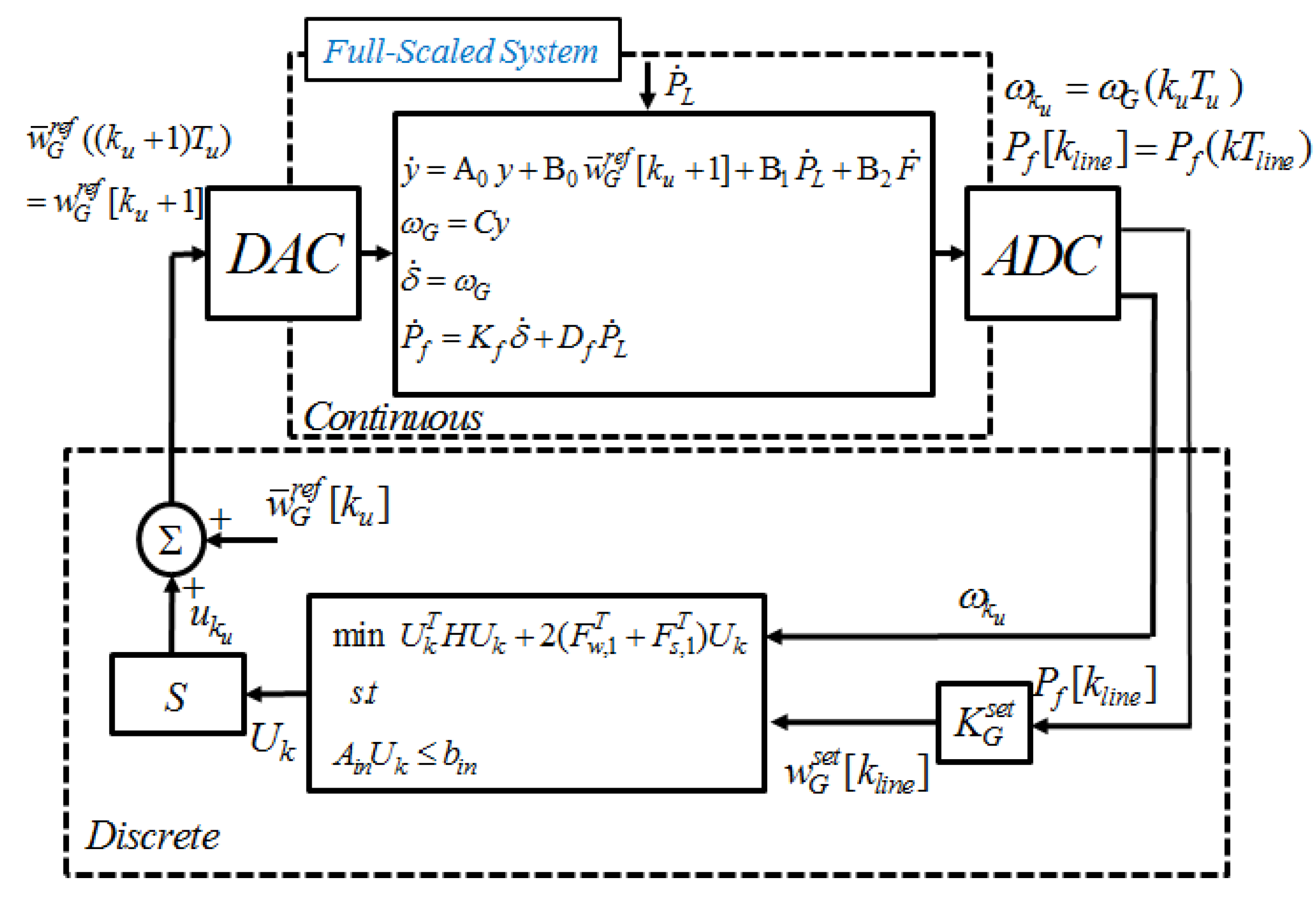
3.1. Centralized MPC-Based AGC

From Equation (8), the discrete-time frequency model with constraints is described as:
ω k + 1 =A ω k + B u k
u ¯ u k u ¯
where ω n is the frequency vector, and u n is the control vector. In this case, n is the total number of generators in the power network. Equation (14) provides the information of each generator regarding a different and limited load reference ramp rate of each capacity per minute (i.e., combustion turbines can develop ramps of approximately 13% to 28% of their capacity per minute [15]).
From Equation (13), the state predictions for an N-step horizon are expressed as follows:
[ ω k + 1 ω k + 2 ω k + N ] = [ A A 2 A N ] ω k + [ B A B A N 1 B 0 B A N 2 B 0 0 B ] [ u k u k + 1 u k + N 1 ]     = M w ω k + C u U k
where Mw is (N × n) × n matrix; Cu is (N × n) × (N × n); and Uk is the N-horizon control set.
The attempt to minimize a squared-weighted sum of state (regulated variables) x and controls u of the given Equation (15) is described by:
J k = i = 0 N 1 ( ω k + i | k Q 2 + u k + i | k R 2 ) + ω k + N | k Q N 2 = U k T H U k + 2 ω k T F w T U k + ω k T G ω k = U k T H U k + 2 F w , 1 T U k + c 0  
where Q, QN, and R are weighting matrices, Q′ = diagonal [Q, Q,…, QN], QN is a weighting matrix for terminal state, and R′ = diagonal [R, R, …R]. H = C u T Q C u + R′ , F w = C u T Q M w , G = M w T Q M w + Q , F w , 1 = ω k F w , and c0 is a constant. H, F w , and G can be computed offline if the system is time invariant.
According to the result of Equation (16), N-horizon optimal control gain Kmpc is –H−1 Fw,1 when the system is unconstrained, and the optimal control u k * is derived by the first horizon gain.

3.2. Line Flow Control in Centralized Structure

In centralized control, the most attractive and distinguishing advantage is to control line flows because loop flows and arrangements for parallel path compensation become increasingly important as the demand for transmission capacity increases at a faster rate than actual capacity [16]. Therefore, we propose the control scheme to stabilize line flows in centralized MPC-based AGC.
From Equation (12), the state transition function for line flows can be described as follows:
P f [ k l i n e + 1 ] = P f [ k l i n e ] + K f ( δ G [ k l i n e + 1 ] δ G [ k l i n e ] ) + D f ( P L [ k l i n e + 1 ] P L [ k l i n e ] )    = P f [ k l i n e ] + K f T l i n e w G s e t [ k l i n e ] + D f d [ k l i n e ]    = A f P f [ k l i n e ] + B f w G s e t [ k l i n e ] + D f d [ k l i n e ]
where kline is the discretized line flow control time step. Load reference set-point signal w G s e t should be considered in Equation (17).
In a typical control design, the set-point command (path) is chosen as a smooth function that has no/few high-frequency components. Therefore, the time step kline of w G s e t should be larger than the frequency control update time ku and the state prediction time step k.
Optimal load reference set-point signal w G s e t * in the infinite horizon can be obtained from minimizing a criterion, such as:
J = k = 0 P f [ k l i n e + 1 ] Q f P f [ k l i n e + 1 ] + w G s e t [ k l i n e ] R f w G s e t [ k l i n e ]
From Equation (18), w G s e t * can be described as:
w G s e t * [ k l i n e ] = K G s e t P f [ k l i n e ]
where:
K G s e t = ( R + B f T P B f ) 1 B f T P A f
0 = A f T P A f P + Q f A f T P B f ( R f + B f T P B f ) 1 B f T P A f
where P is the solution to the discrete algebraic Riccati equation [17,18].
To drive the system to some other set-point w G s e t , wk can be replaced with:
w k s = ω k w G s e t
The state transition function in Equation (13) can be expressed as:
w k + 1 s = A ( ω k w G s e t ) + B u k ( I A ) w G s e t    =A w k s + B u k + η
where η = – ( I A )   w G s e t .
On the basis of Equation (23), the predictive states for system frequency with a non-zero set-point   w G s e t can be re-expressed as follows:
w k + i s = A i w k s + j = 1 i A i j B u k + j 1 + j = 1 i A j 1 η
W = M w w k s + C u U k + D s η
where Ds is the (N × n) × n matrix.
The attempt to minimize a squared-weighted sum of state (regulated variables) w and control u of the given Equation (26) is described by:
J k = i = 0 N 1 ( w k + i | k s Q 2 + u k + i | k R 2 ) + w k + N | k s Q N 2 = ( M w w k s + C u U k + D s η ) T Q ( M w w k s + C u U k + D s η ) + U k T R U k + w k s , T Q w k s = U k T H U k + 2 ( F w , 1 T U k + F s , 1 T ) U k + c 1
where Fs,1 = C u T Q D s η ; c1 is a constant.
In consideration of input constraints, the optimization of Equation (26) can be expressed as a quadratic program optimization:
   min   1 2 U k T H U k + ( F w , 1 T + F S , 1 T ) U k subject to    A i n U k b i n
where Ain and bin express the load reference ramp constraints among generators.
The control gain Kmpc is with –H−1 (Fw,1 + FS,1) when the constraints are not activated. This value can be varied because of the activation of constraints. Figure 1 shows the centralized MPC-based AGC system. In this figure, S is the function to select the control at the first horizon.
Figure 1. Centralized MPC-based AGC Considering Line-flows.
Energies 08 03437 g001

3.3. Distributed MPC-Based AGC

In the distributed MPC-based approach, each BA is assumed to be unaware of the state variables and control inputs in other BAs when its EMS computes AGC signals. Therefore, this paper provides individual AGC signals in each BA which mainly maintain their area frequency.
The major difference from centralized control is that the full-scale dynamic system in Figure 1 is affected from individual and unsynchronized AGC signals derived from each BA. Moreover, these signals in each BA are only responsible for maintaining a nominal frequency without any information for other area frequencies. This situation signifies that individual tie-line flow control is impossible in distributed MPC-based AGC because the angles δ in Equation (10) are affected by the power deviations in other areas, and these inadvertent tie-line flows eventually changes the frequencies in each BA.
To maintain frequency and tie-line flows at the same time, AGC signals in distributed BAs are traditionally computed by minimizing ACE, which can be described as:
Δ A C E i = β i Δ w i , k r + Δ P i , k n e t
where i is the area number, β is the frequency bias factor, w i , k r is a representative frequency at area i, and P i , k n e t is the net inadvertent tie-line flow. When ACE is minimized, the tie-line control action in each BA is not a topological problem and is another form of active power balancing in each BA. Based on this scheme, EMS considers the system-wide effect of local control actions in each BA.
Following the same principle as ACE, we propose the pseudo-frequency at i-BA, which is described by:
Δ w i , k p s = Δ w i , k + Η b d Δ P i , k n e t
where H b d is the block diagonal matrices with 1 / β . The pseudo-frequency substitutes the measured frequency wk in Equation (13) while EMS computes MPC-based AGC signals. Figure 2 shows the distributed MPC-based AGC system. In the figure, Ti is the function to compute H b d P i , f n e t from individual tie-line flows in i-BA.
Figure 2. Distributed MPC-based AGC.
Energies 08 03437 g002

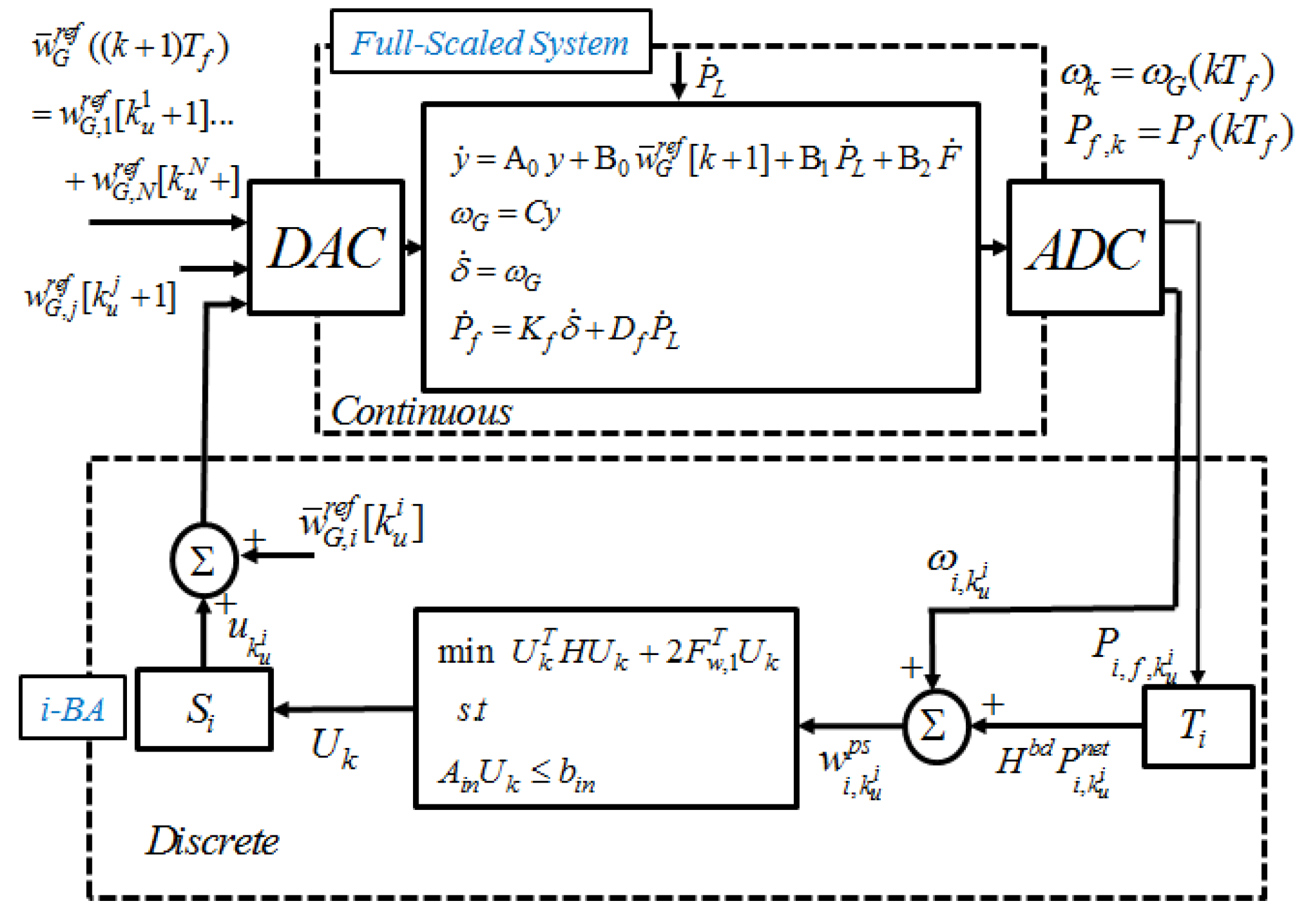
3.4. Bulk-Area Partitioning for MPC-Based AGC

Reference [6] showed that the average time for optimization in the MPC-based approach increases exponentially as the prediction horizon increases, but the desirable dynamic performance is only obtained when the prediction horizon is large enough. The average time for optimization also increases exponentially as the number of generators increases.
In the field, the numbers of participating generators exist in AGC, and the AGC signals should be rapidly computed for approximately 2 s [10]. Therefore, considering the computation time in the MPC-based approach is important in the design process.
The present research proposes bulk-area partitioning in bulk BAs. In the proposed scheme, each subsystem in a bulk BA has its own AGC scheme in EMS, such as a BA, and the net tie-line flows among subsystems is recomputed by the upper controller in its BA. The net of tie-line flows among subsystems is described as:
Δ P i s , k n e t = j = 1 n A Δ P i j [ k ]    O r i g i n a l N e t   T i e l i n e   F l o w s + ( Δ P m , i s n e t [ k m ] 1 n i k = 1 n i Δ P m , i k n e t [ k m ] ) P a r t i t i o n i n g   C o n t r o l   i n   B A   i
where n A is the number of BAs, n i is the number of subsystems in BA i,   P i s j is the power flow from subsystem is to BA (or subsystem) j, k m is the discretized mechanical power sampling time step, and Δ P m , i k n e t is the net of deviated mechanical power output in subsystem i k . According to this control scheme, each subsystem equally reacts to the discrepancy between the generation supply and the total MW obligation in its BA. In this case, the function T i in Figure 2 includes the control process for Equation (30).

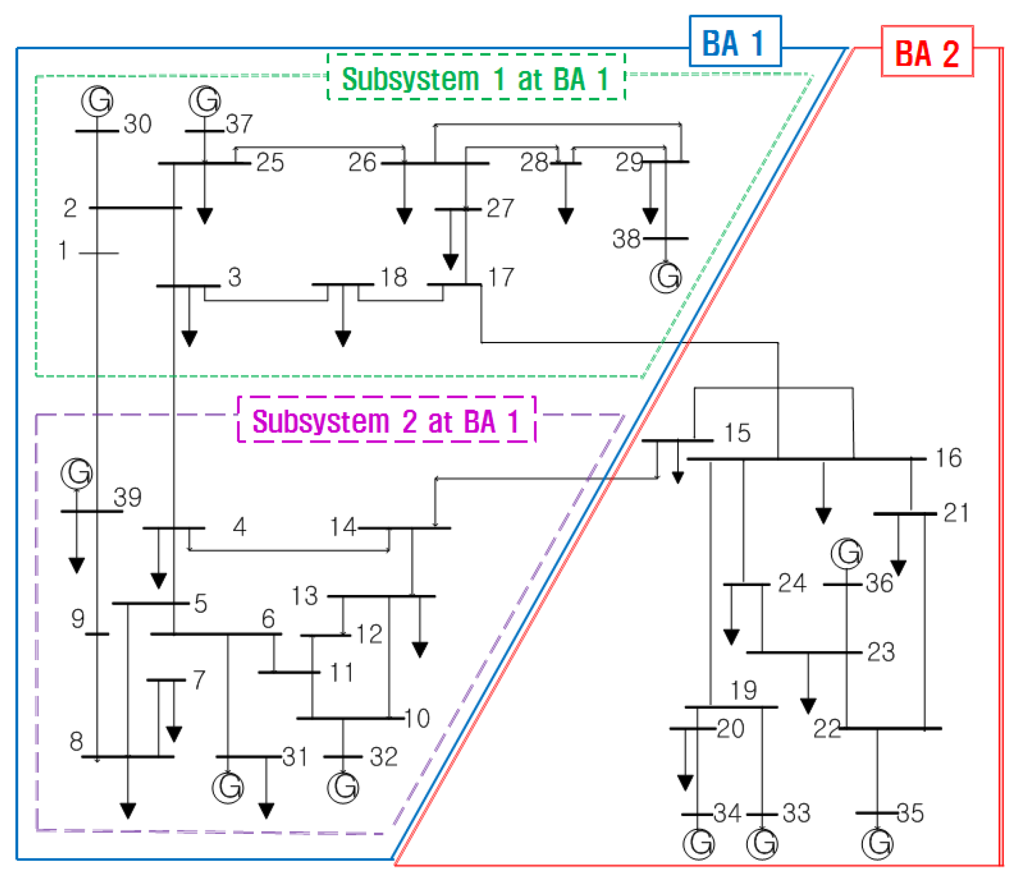
4. Illustrative Example

Simulation is conducted on a modified New England 39-bus system, as shown in Figure 3; per-unit bus voltage, bus angle, and transmission line data given in [19,20] are used. Table 1 lists the parameters and load reference constraints for the generator dynamic models at each bus. Table 2 lists the load disturbance information.
This simulation demonstrates the results of both centralized and distributed MPC-based AGC. The MPC-based operation results are analyzed from the perspectives of computational burden and dynamic performance.
Figure 3. IEEE 39 Bus Systems with Two Bas.
Energies 08 03437 g003
Table 1. Parameters and load reference ramp constraints for generators.
Generator BusMDTgTaKtr u ¯ ( 10 4 ) u ¯ ( 10 4 )
# 30 (Gen1)250.250.2250193−3
# 31 (Gen2)350.250.2250193−3
# 32 (Gen3)250.250.2250192−2
# 33 (Gen4)250.250.2250192−2
# 34 (Gen5)350.250.2250193−3
# 35 (Gen6)250.250.2250193−3
# 36 (Gen7)250.250.2250193−3
# 37 (Gen8)250.250.2250193−3
# 38 (Gen9)350.250.2250192−2
# 39 (Gen10)250.250.2250192−2
Table 2. Step load deviation events.
Event time [s]Bus numberMagnitude [pu]
1280.2
5013-0.1
100220.15

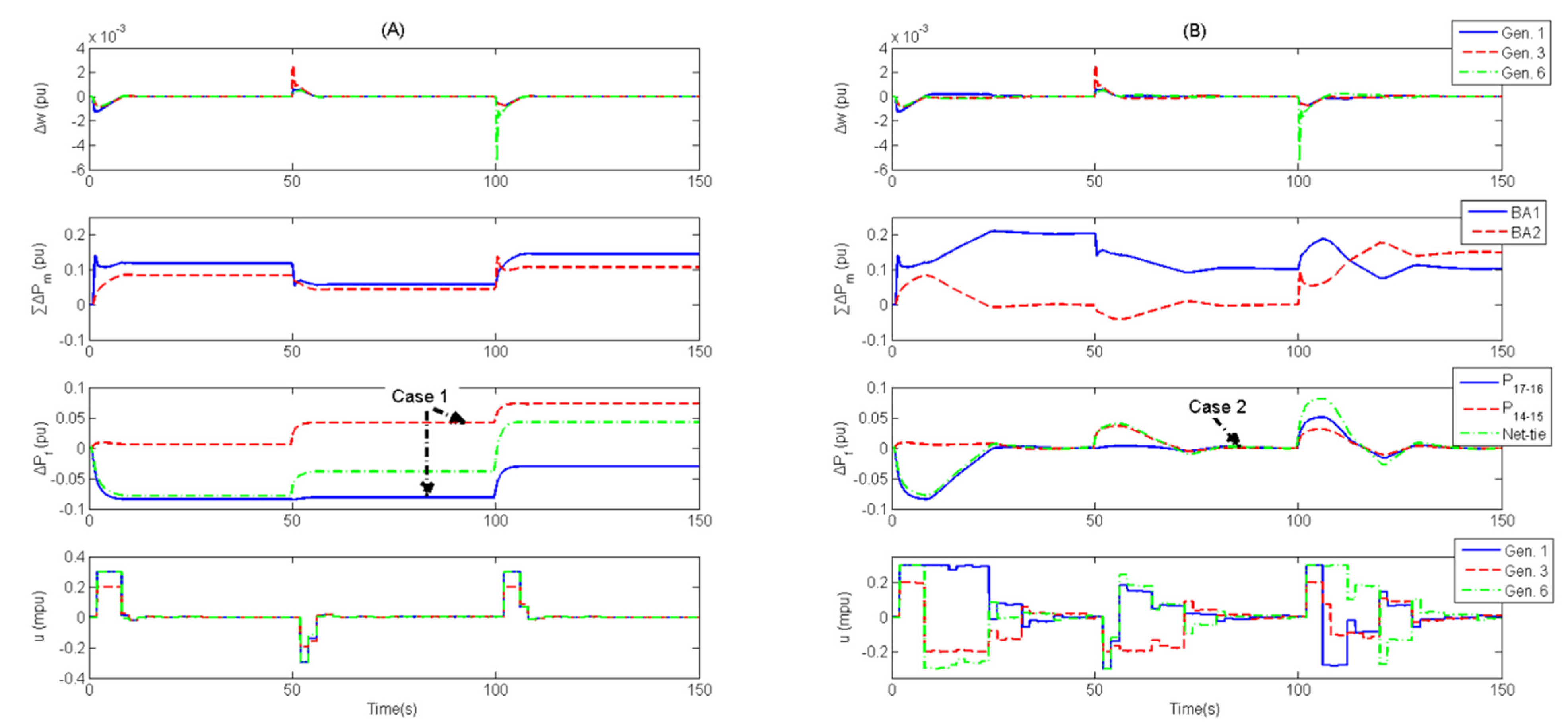
4.1. Centralized MPC-Based AGC Systems

Table 3 lists the data and parameters for the centralized MPC-based control simulation. In Figure 4, each case shows that frequencies and line flows are maintained by the given control scheme. In this simulation, the proposed centralized controller maintains line flows P 17 16 and P 14 15 . Therefore, the 39-bus system naturally divides into two areas, BA1 and BA2 (Figure 3). We use a two-area notation rather than the original single-area notation to compare the centralized MPC-based results with the distributed MPC-based results.
Figure 4. Centralized MPC-based AGC: (A) Without Line Flow Control (Original Case) (B) With Line Flow Control (Proposed).
Energies 08 03437 g004
Table 3. Data and parameters for centralized MPC-based AGC.
DescriptionParameterValue
Discretized Minimum Step Time [s]Tf1
AGC Update Time [s]Tu2
Line Control Update Time [s]Tline6
Weighting MatrixQ102I
QN102I
RI
QfIline
RfI
Prediction HorizonN20
Frequency Bias Factor β 200
- I is a 10-by-10 identity matrix. - Iline is a 2-by-2 identity matrix.
Centralized control provides successful dynamic performance on stabilizing frequency. Figure 4A shows that each frequency at generator buses is rapidly maintained. Given that the centralized controller solves the optimization problem in consideration of the entire system dynamic behavior, its solution provides better dynamic performance than the distributed MPC-based solution. The specific results will be provided in the following section. In Figure 4B, each BA is responsible for its discrepancy between the generation supply and the total MW obligation through line flow control. This centralized controller adjusts the load references among generators to maintain the frequency every 2 s and to stabilize the inadvertent line flows every 6 s. The results show that BA1 and BA2 at 150 s produce powers of 0.1 and 0.15 pu respectively as the load deviations in each BA. This line control scheme secures state controllability while the number of designated lines is fewer than the generators involved in the line flow control. In the simulation, the controllability in Equation (17) is satisfied because two line flows are controlled by 10 generators. On the basis of this control property, the system operator can design AGC to maintain frequency in consideration of designated and important line flows.
This line control scheme helps the system operator reduce wheeling, which is a loop flow caused by network topology. In the field, wheeling increases the power losses or the overloading of network elements. Therefore, wheeling must be considered to minimize operation cost and secure system reliability. However, most of the previous MPC-based schemes, which did not consider network topologies, could not provide any method to minimize the loop flows such as the results at Case1 in Figure 4A. Based on the proposed control scheme, designated lines are effectively adjusted as shown at Case2 in Figure 4B, and it can help the system operators to reduce the power losses or the overloading of network elements.

4.2. Distributed MPC-based AGC Systems

Table 4 and Table 5 list the data and parameters for distributed MPC-based control simulation. All the conditions are assumed to be the same as in Table 3, except for discretized control update times and frequency bias factors at each BA. In case of bulk-area partitioning, BA1, as shown in Figure 3, has two subsystems with their own frequency controllers, and the mechanical power outputs in each subsystem are controlled by an upper controller in BA1 every 4 s. Each BA has its own controller. These distributed controllers in BA1 and BA2 adjust the load references among generators to maintain frequency and to stabilize net-tie line flows for control update times of 3 and 2 s respectively. As shown in Figure 5, the load reference of Gen.6 is more smoothly updated than those of other generators in BA1.
Wheeling is an intractable and uncontrollable problem in a distributed control structure. In Figure 5, the net tie-line flow is maintained at zero, but the individual tie-line flows are different from the initial tie-line flows. This circumstance indicates that this control scheme suffers from the increase in power losses in the intervening systems or the overloading of network elements. Therefore, the load references should be recomputed among generators in BAs while wheeling makes significant effects.
Table 4. Data and parameters for MPC-based AGC in each BA.
DescriptionParameterBA1BA2
Discretized Minimum Step Time [s]Tf1 1
AGC Update Time [s]Tu32
Weighting MatrixQ102I1102 I2
QN102 I1102 I2
RI1I2
Prediction Horizon N 2020
Frequency Bias Factor β 12080
- I1 is a 6-by-6 identity matrix; - I2 is a 4-by-4 identity matrix.
Table 5. Data and Parameters for Bulk-Area Partitioning in BA1.
DescriptionParameterSB1SB2
Mechanical power sampling time [s]Tm4
Q102Isb1102 Isb2
Weighting MatrixQN102 Isb1102 Isb2
RIsb1Isb2
- SB is subsystem; - Isb1 and Isb2 are 3-by-3 identity matrices.
In the bulk-area partitioning control scheme, each subsystem in BA1 equally generates the discrepancy between the generation supply and the total MW obligation. In Figure 5, although the mechanical power outputs among subsystems are different and do not become equal at Case 1, the results at Case 2 have the same mechanical power values in each subsystem. These results show that each subsystem shares its power generation capacities. Although this research does not consider the discriminative power sharing scheme in Equation (30), such a scheme should be cautiously considered in the future when renewable power sources and microgrids are briskly utilized in power system because these entities can produce large disturbances (PL and F) to increase their profits.
Figure 5. Distributed MPC-based AGC: (A) Without Partitioning (Original Case); (B) With Partitioning (Proposed Case).
Energies 08 03437 g005
Bulk-area partitioning dramatically reduces the computation time and ensures dynamic performance. In this simulation, each subsystem has three generators, half of the original six generators in BA1. Therefore, the object function in Equation (27) is much rapidly solved. In Figure 6, the results show the computation times in accordance with the horizon sizes and the number of states by using an Intel Core i5 CPU 750 @2.67 GHz and 2 GB of RAM. The prediction horizon size (N) affects the dynamic performance in stabilizing frequency and tie-line flows. Therefore, its size is manually chosen in accordance with the user-defined (or system) dynamic performance requirements. However, the number of generators is fixed and cannot be changed to a small value. In the MPC-based scheme, the numbers of generators in bulk areas will lead to computational burden, although simply modified SISO-based schemes, such as proportional–integral-based AGC, do not suffer greatly from this problem. The proposed bulk-area partitioning can mitigate this difficulty in solving a massive QP problem at a time by dividing the original state function. In addition, the results of the proposed scheme only present a slight difference in dynamic performance compared with the results in the (A) original case. This situation signifies that the bulk-area partitioning control scheme can provide substantial and realistic measures for suffering from “curse of dimensionality” as a desired result.
Figure 6. Average computation times according to operation conditions.
Energies 08 03437 g006

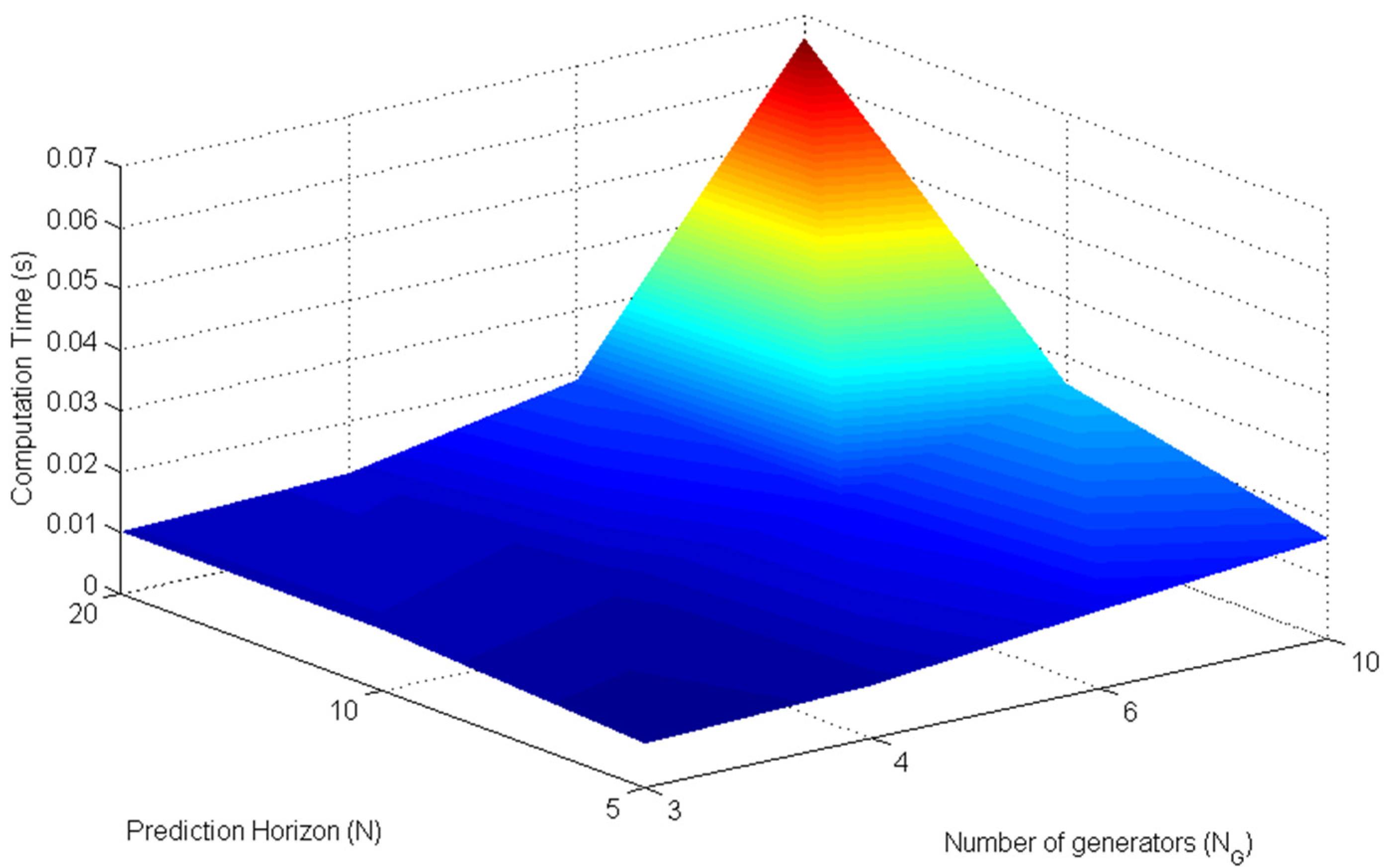
4.3. Discussion on Structure-Dependent AGC Scheme

Based on the tested simulation results, structure-dependent MPC-based AGC can be considered, as shown in Table 6. Each scheme has unique advantages and disadvantages. Given that centralized control considers the entire system dynamic behavior, this scheme in the original case provides improved settling time results. However, centralized controllers in bulk-power systems have severe problems (Table 6). Therefore, under the control design process, system operators should cautiously analyze whether or not to satisfy the system requirements in designated MPC-based AGC structure.
Centralized line flow control schemes poorly stabilize frequencies in comparison with the results in the original case. However, the difference can be ignored when the line control update time Tline is set to a large value. These results show a tradeoff between dynamic performances in stabilizing frequency and line flows. Therefore, the system operator should carefully choose Tline in consideration of the system operation requirements and economics.
Table 6. Structure-dependent MPC-based AGC.
Considerations for implementationCentralized structureDistributed structure
OriginalProposedOriginalProposed
WheelingΧ О ΧΧ
Computation TimeΧΧ Ο
PracticalityΧΧ Ο Ο
Settling time (Tst) [s]7.6024.6015.0516.01
- Χ: severe, ∆: less severe, Ο : least severe; - Tst: The maximum time required for every generator frequency curve to stay within a range of certain percentage 0.01% (0.1 mpu) of the nominal frequency from the first disturbance 0.2 pu at Bus 28.
The proposed structure-dependent MPC-based AGC schemes can help system operators prepare for future power systems. Due to increasing profit-seeking entities such as wind-farm producers and microgrid operators, sharing the responsibility of deviated system frequency (or power imbalance) among entities can be critical and will be a very important issue in future. Based on proposed control structures, it is possible to consider how to share the responsibility of the deviated system frequency or design the operation rules. For instance, a system operator in a centralized structure should be responsible for stabilizing frequency by himself. However, he can reduce the computational burden as well as his responsibility via the proposed bulk-area partitioning control scheme since owners (operators) in subsystems are required to build dispatchable power resources to meet the contraction like Equation (30).
On the basis of the research findings, we propose to establish a centralized organization among distributed BAs to control individual tie line flows. In the proposed control scheme, line flow control signals are separately computed from the signals to stabilize the frequency, as shown in Figure 1. This situation signifies that the centralized line controller is a different control system and is interpreted as an additional organization. Therefore, founding a centralized organization among distributed BAs can help system operators to increase profits from the interconnection when system-wide wheeling causes significant effects. The limitation of computation capacity is not a significant problem in this control scheme because Tline is usually larger than Tu.

5. Conclusions

This paper presented an MPC-based AGC considering network topology. Based on the proposed MPC-based control process, the optimal AGC signal was obtained by solving a constrained QP, which revealed a significant advantage in terms of optimization procedure. In this simulation, the time for one step was approximately 70 ms when the MPC-based approach considered 20 prediction horizons and 10 generators.
This research mainly dealt with structure-dependent control schemes. To strengthen the advantages and minimize the disadvantages, different approaches were developed from previous MPC-based studies. In the centralized control structure, this research proposed designated line flow control to strengthen its unique advantages. The results showed that the proposed control effectively reduces inadvertent line flows in its area, signifying that wheeling is a manageable problem in this control scheme. In the distributed control structure, this research mainly considered bulk BAs from a computational perspective because the number of generators dramatically increases the computation time. Therefore, bulk-area partitioning was developed, and this proposed scheme provides only a slight difference in dynamic performance compared with original case result in the distributed structure. This research also proposed to establish a centralized organization among distributed BAs to manage individual tie-line flows when wheeling makes system-wide effects. This organization can help system operators to increase the profits from tie-line interconnections among BAs. In future works, we plan to obtain economic MPC-based AGC with performance constraints. This study will help system operators to reduce the operation cost of generators for AGC.

Nomenclature

The main symbols that appear in this paper are defined below. Other symbols are defined in the text as they appear.

Constants:

V
Bus voltage [pu]
δ
Bus voltage angle [radian]
P
Initial bus power generation or demand [pu/100 MW]
Ta
Time constant of the turbine [s]
Tg
Time constant of governor [s]
Tf
Discretized minimum time step [s]
Tu
Discretized automatic generation control update time [s]
Tm
Discretized mechanical power sampling time step [s]
Tline
Discretized line power flow control update time step [s]
Tst
Frequency settling time [s]
D
Damping constant
M
Moment of inertia of the generator [s]
Kt
Parameter in linearization for turbine characteristics
r
Parameter in linearization for governor droop characteristics
J
Jacobian matrix of power evaluated at angle
β i
Frequency bias factor in i-balancing area
u ¯
Maximum generation control ramp rate [pu/s]
u ¯
Minimum generation control ramp rate [pu/s]

Variables:

w G r e f
Load reference [pu]
w G s e t
Load frequency set point [pu]
ω G
Generator frequency [pu]
Pm
Turbine mechanical power [pu]
α
Governor-controlled valve opening [pu]
F
Mapped injected-power [pu]
Pf
Tie-line power flow [pu]
y
Concatenated state variables in full-scale dynamic model

Indices:

k
Discretized minimum time step [k = kTf]
ku
Discretized frequency control update time step [ku = kuTu]
Kline
Discretized tie-line flow control update time step [kline = klineTline]
km
Discretized mechanical power sampling time step [km = kmTm]

Author Contributions

The main idea of this paper is suggested by Young-Sik Jang. He completed the mathematical modeling, simulations and wrote the first draft of the paper. JoonHyung Park contributed to the mathematical modeling and thoroughly reviewed the paper. Yong Tae Yoon coordinated the main theme of this paper and thoroughly reviewed the paper.

Conflicts of Interest

The authors declare no conflict of interest.

References

  1. Zhang, G. EPRI Power System Dynamics Tutorial; Report 1016042; Electric Power Research Institute: Palo Aoto, CA, USA, 2009. [Google Scholar]
  2. Rossiter, J.A. Model-Based Predictive Control: A Practical Approach; CRC: Boca Raton, FL, USA, 2003. [Google Scholar]
  3. Mohamed, T.H.; Bevrani, H.; Hassan, A.A.; Hiyama, T. Model predictive based load frequency control design. In Proceedings of the 16th International Conference of Electrical Engineering, Busan, Korea, 11–14 July 2010; pp. 1–6.
  4. Kong, L.F.; Xiao, L. A new model predictive control scheme-based load-frequency control. In Proceedings of the IEEE International Conference on Control and Automation, Guangzhou, China, 30 May–1 June 2007; pp. 2514–2518.
  5. Yousef, A.M. Model predictive control approach based load frequency controller. WSEAS Trans. Syst. Cont. 2011, 6, 265–275. [Google Scholar]
  6. Camponogara, E.; Jia, D.; Krogh, B.H.; Talukdar, S. Distributed model predictive control. IEEE Control Syst. Mag. 2002, 22, 44–52. [Google Scholar] [CrossRef]
  7. Venkat, A.; Hiskens, I.; Rawlings, J.; Wright, S. Distributed MPC strategies with application to power system automatic generation control. IEEE Trans. Control Syst. Technol. 2008, 16, 1192–1206. [Google Scholar] [CrossRef]
  8. Nong, H.; Liu, X. Nonlinear distributed MPC strategy with application to AGC of interconnected power system. In Proceedings of the Control and Decision Conference (CCDC), Qingdao, China, 25–27 May 2013.
  9. Ma, M.; Chen, H.; Liu, X.; Allgöwer, F. Distributed model predictive load frequency control of multi-area interconnected power system. Int. J. Electr. Power Energy Syst. 2014, 62, 289–298. [Google Scholar] [CrossRef]
  10. Kundur, P. Power System Stability and Control; McGraw-Hill: New York, NY, USA, 1994; pp. 581–613. [Google Scholar]
  11. Mohamed, T.H.; Bevrani, H.; Hassan, A.A.; Hiyama, T. Decentralized model predictive based load frequency control in an interconnected power system. Energy Convers. Manag. 2011, 52, 1208–1214. [Google Scholar] [CrossRef]
  12. Ilic, M.; Zaborszky, J. Dynamics and Control of Large Electric Power Systems, 1st ed.; John Willey and Sons Inc.: Hoboken, NJ, USA, 2000; pp. 352–370. [Google Scholar]
  13. Liu, X. Structure Modeling and Hierarchical Control of Large Scale Electric Power System. Ph.D. Dissertation, Department of Electrical Engineering and Computer Science—Massachusetts Institute of Technology, Cambridge, MA, USA, 1994. [Google Scholar]
  14. Eidson, B. Estimation and Hierarchical Control of Market-driven Electric Power Systems. Ph.D. Dissertation, Department of Electrical Engineering and Computer Science—Massachusetts Institute of Technology, Cambridge, MA, USA, 1995. [Google Scholar]
  15. Makarov, Y.V.; Ma, J.; Lu, S.; Nguyen, T.B. Assessing the Value of Regulation Resources Based on Their Time Response Characteristics; CERTS Report PNNL-17632; Pacific Northwest National Laboratory: Richland, WA, USA, 2007. [Google Scholar]
  16. Wood, A.J.; Wollenbergy, B.F. Power Generation, Operation, and Control; Wiley: New York, NY, USA, 1984. [Google Scholar]
  17. Phillips, C.L.; Nagle, H.T. Digital Control System, 2nd ed.; Prentice Hall: Upper Saddle River, NJ, USA, 1990; pp. 356–372. [Google Scholar]
  18. Bertsekas, D.P. Dynamic Programming and Optimal Control, 1st ed.; Athena Scientific: Belmont, MA, USA, 1995; Volume 1, pp. 130–157. [Google Scholar]
  19. Pai, M.A. Energy Function Analysis for Power System Stability; Kluwer Academic Publishers: Boston, MA, USA, 1989. [Google Scholar]
  20. Zimmerman, R.D.; Murillo-Sanchez, C.E.; Gan, D. MATPOWER 5.0.0 User’s Manual. Available online: http://www.pserc.cornell.edu//matpower/ (accessed on 17 December 2014).

