Article

Adaptive State of Charge Estimation for Li-Ion Batteries Based on an Unscented Kalman Filter with an Enhanced Battery Model

1
College of Electric Information, Hangzhou Dianzi University, 2nd Street, Xiasha Higher Education Zone, Hangzhou 310018, China
2
Department of Electrical and Computer Engineering, Wayne State University, 5050 Anthony Wayne Drive, Detroit, MI 48202, USA
*
Author to whom correspondence should be addressed.
Energies 2013, 6(8), 4134-4151; https://doi.org/10.3390/en6084134
Submission received: 28 May 2013 / Revised: 30 July 2013 / Accepted: 6 August 2013 / Published: 12 August 2013
(This article belongs to the Special Issue Li-ion Batteries and Energy Storage Devices)

Abstract

:
Accurate estimation of the state of charge (SOC) of batteries is one of the key problems in a battery management system. This paper proposes an adaptive SOC estimation method based on unscented Kalman filter algorithms for lithium (Li)-ion batteries. First, an enhanced battery model is proposed to include the impacts due to different discharge rates and temperatures. An adaptive joint estimation of the battery SOC and battery internal resistance is then presented to enhance system robustness with battery aging. The SOC estimation algorithm has been developed and verified through experiments on different types of Li-ion batteries. The results indicate that the proposed method provides an accurate SOC estimation and is computationally efficient, making it suitable for embedded system implementation.

1. Introduction

Batteries have been widely used in many applications where electric energy storage is needed, such as renewable energy systems, telecommunication power supplies, electric power systems, military applications, and electric transportation systems [1,2,3,4,5]. The high electrochemical potential and energy density of lithium (Li) make Li-ion batteries a very promising solution for the storage of electric energy. The SOC of a battery cell is defined as the ratio of the remaining capacity to the nominal capacity of the cell. It is one of the most important battery state variables, and an accurate SOC gauge is critical to the optimal management of batteries [6]. Unfortunately, the SOC cannot currently be measured directly but must be estimated via other measurements. Consequently, in real applications, battery SOC estimation is one of the core challenges in battery management systems (BMSs) [7].
Typical methods for SOC estimation include ampere-hour (AH) counting (e.g., Coulomb counting), inverse nonlinear mapping from the open circuit voltage (OCV) to the SOC, the Kalman filter (KF) [8] and its extensions [7,9,10,11], [e.g., the extended KF (EKF) and unscented KF (UKF)], artificial neural network (NN)-based methods [12], and fuzzy logic-based methods [13]. Because the KF cannot be used directly for state prediction of a nonlinear system, the EKF- [7,9] and UKF-based methods [10] are the most widely used. However, the EKF must compute the Jacobian matrix and is generally not suitable for highly nonlinear systems with non-Gaussian noise. Similar to the EKF, the UKF is another extension of the KF and is also a recursive minimum mean square error (MMSE) estimator. The UKF has been demonstrated to outperform the KF and EKF in terms of accuracy and robustness for nonlinear estimation. The UKF does not need to calculate the Jacobian matrix and does not require noise to be Gaussian, which makes it more appealing for SOC estimation because battery systems are highly nonlinear and the noise properties are typically not known.
Battery models are the basis for SOC and model parameter estimation. Various types of battery models have been developed and utilized, including electrochemistry-based models [14,15], equivalent electrical circuit-based models [3,16,17,18], and mathematical models [19,20,21,22,23].
This paper contributes to this field in the following key aspects: (1) an enhanced battery model is proposed to include the impact of different charge/discharge rates and temperatures. It is well known that battery maximum capacities depend significantly on charge/discharge currents and operating temperatures. The model is structured as the ratio of two functions, one as a function of the temperature and the other of the charge/discharge rate. This model structure represents data well, allows us to employ simple polynomials to represent each function, and has the flexibility of using one function under a fixed temperature or fixed current condition; (2) a recursive UKF-type algorithm for SOC estimation is developed under this new battery model with model validations. Introduction of submodels for temperature and current rate complicates model nonlinearity, and makes the standard KF or EKF less reliable, and the UKF a more suitable choice. While the generic UKF is well known and has been applied to battery SOC estimations, its usage in the new model structure is new and requires detailed derivations and validations. To accommodate practical constraints, we have also discussed the scenarios of unknown but estimated noise characteristics; (3) an online UKF-based algorithm for adaptive joint estimation of the battery SOC and the battery internal resistance is introduced. The joint estimation algorithm captures this battery aging effect, which can potentially be used for SOH (state of health) estimation or battery diagnosis.
To gain a better perspective of our contributions, a comparative analysis with the existing literature is in order. It has been well recognized that battery model parameters and the SOC are highly coupled [24], which requires joint system parameter identification and SOC estimation. A joint estimation method to obtain the battery parameters and SOC simultaneously was reported in our earlier paper [24]. The models of [24] assume an unknown but fixed capacity without consideration of its dependence on temperature and charge/discharge current. Also, it uses a recursive least-squares-type algorithm with different convergence features. The underlying battery models and algorithms of this paper are different from those in [24], and hence provide different features. A comprehensive summary of BMSs for electric and hybrid vehicles was presented in Xing et al. [25], in which battery state evaluation and battery modeling were listed as the major concerns. The proposed UKF-based SOC estimation method with the enhanced battery model in this paper adds new tools and algorithms to SOC estimation methodologies, and as a result can potentially enhance BMSs by addressing their core challenges. Battery parameter estimation is related to SOH estimation, which is another important task in BMSs. He et al. [26] introduced some interesting and important approaches for SOH estimation and prediction. In [26], the capacity fading was modeled by the sum of two exponential functions of discharge cycles with the internal impedance as a key parameter in the exponential function. Our paper incorporating temperature and current rate factors into the models with different model structures. Although SOH estimation is not the focus of our paper, the jointly estimated internal resistance serves the dual purposes of enhancing SOC estimation accuracy and indicating the battery SOH and detecting faults. In this aspect, our results complement those of [26].
The remainder of the paper is organized as follows: battery models are discussed in Section 2. The temperature and rate model structures are introduced, leading to an enhanced battery model. The SOC estimation algorithm based on the UKF methodology under the new model structure is derived in Section 3. Recursive algorithm structures are detailed and their estimation accuracy and prediction capability are established. In Section 4, an online algorithm for joint estimation of the battery SOC and internal resistance is presented. The paper concludes with some discussions on the main findings and open issues in Section 5.

2. An Enhanced Battery Model

A battery can be treated as a dynamic nonlinear system, and many of its characteristics can be included in the state vector. The choice of state variables can be important in modeling a battery. SOC estimation is our aim in this paper. Therefore, the battery’s SOC is chosen as an element of the state vector. The two sub-models in the proposed UKF-based methods, namely, the process model and measurement model, describe the relationship between the SOC and measured battery quantities, such as the terminal voltage, current, and temperature.

2.1. The Process Model

The SOC z(t) of a battery at time t is defined as the ratio of the remaining capacity Q(t) that can be drawn from the battery to its nominal capacity Qn:
Energies 06 04134 i001
Here, the capacity is dimensioned by ampere-hours, which is an accumulation of the discharge current according to time. The nominal capacity Qn is the maximum capacity that can be drawn from the battery with a constant discharge rate of C/30 at room temperature (25 °C), where C is the current that will fully discharge the battery from a fully charged state in exactly 1 h at room temperature. The remaining capacity Q(t) is highly related to the working states of the battery, such as temperature, discharge rate, cell aging, and cell self-discharging.
The influence of temperatures on the total capacity that can be drawn from the battery is shown in Figure 1. The example is a LiFePO4 battery with a nominal capacity of 15 Ah. The data in Figure 1 were obtained with the help of a thermal chamber. A fully charged battery was first put into the constant-temperature thermal chamber for a certain period of time. Then, the battery was discharged under a constant discharge rate of C/30 until its nominal cut-off voltage was reached. The total capacity was calculated by the multiplication of the discharge rate and discharge time. The entire process was repeated several times under each temperature, until all of the data were obtained.
Figure 1. Capacity ratios under different temperatures.
Energies 06 04134 g001
The influence of discharge rates on the total capacity that can be drawn from the battery is shown in Figure 2. The battery was also initially fully charged and then fully discharged with a constant discharge rate under a constant room temperature of 25 °C. The total capacity was calculated in a similar manner, and the discharging process was repeated several times with different discharge rates until all of the data were obtained.
As observed from Figure 1 and Figure 2, when the battery works under permitted conditions, a larger share of the total capacity can be drawn as the temperature increases. In contrast, a smaller share of the total capacity can be drawn as the discharge rate increases. In this paper, we model this phenomenon separately by two quantities QT and Qi. QT is the total capacity that can be drawn from the battery when it is discharged at a temperature of T at a constant discharge rate of C/30. Qi is the total capacity that can be drawn from the battery when it is discharged at a discharge rate (current) of i at room temperature.
Figure 2. Battery capacity ratios under different discharge rates.
Energies 06 04134 g002
In this paper QT is modeled as a second-order polynomial, whereas Qi is modeled as a fourth-order polynomial, i.e.:
QT = a2T2 + a1T + a0
Qi = b4(i/C)4 + b3(i/C)3 + b2(i/C)2 + b1(i/C) + b0
where A = [a2, a1, a0] and B = [b4, b3, b2, b1, b0] are coefficients of the two polynomials.
Considering the significant influence of temperature and discharge rate, the SOC z(t) at time t can be described with the following equation according to Equation (1) of the SOC, i.e.:
Energies 06 04134 i002
where z(0) is the initial SOC; η is the Cell Coulombic efficiency and η = 1 for discharge; i(τ) is the instantaneous discharging current at time τ; and μ is the dimensionless proportion coefficient, which is a function of current i and temperature T:
Energies 06 04134 i003
For discharge, Equation (4) can be discretized into the following equation when the KF is utilized for recursion, i.e.:
Zk+1 = h(Zk, ik) = Zk − (μ(ik, Tkt/Qn)ik
where Δt is the sampling time interval when the system is discretized. Equation (6) is the process (state transfer) model for the battery system.
We substitute Equations (2) and (3) into Equation (5) and then substitute Equation (5) into Equation (6) to obtain:
Energies 06 04134 i004
As observed from Equation (7), the SOC is highly nonlinear to the discharging current and working temperature.

2.2. The Measurement Model

The measurement model of a battery yields the battery terminal voltage in terms of its current, temperature, and SOC. The combined measurement model in [9] is also used in this paper, given as follows:
yk = g(p, ik, Zk) = K0RikK1/ZkK2Zk + K3lnZk + K4ln(1 − Zk)
In the above model, yk is the battery terminal voltage; ik is the battery current; Zk is the SOC of the battery; R is the internal resistance of the battery; and K0 to K4 are empirical constants. p = [K0, R, K1, K2, K3, K4]T is the parameter vector. As observed from Equation (8), the battery measurement model is also highly nonlinear.

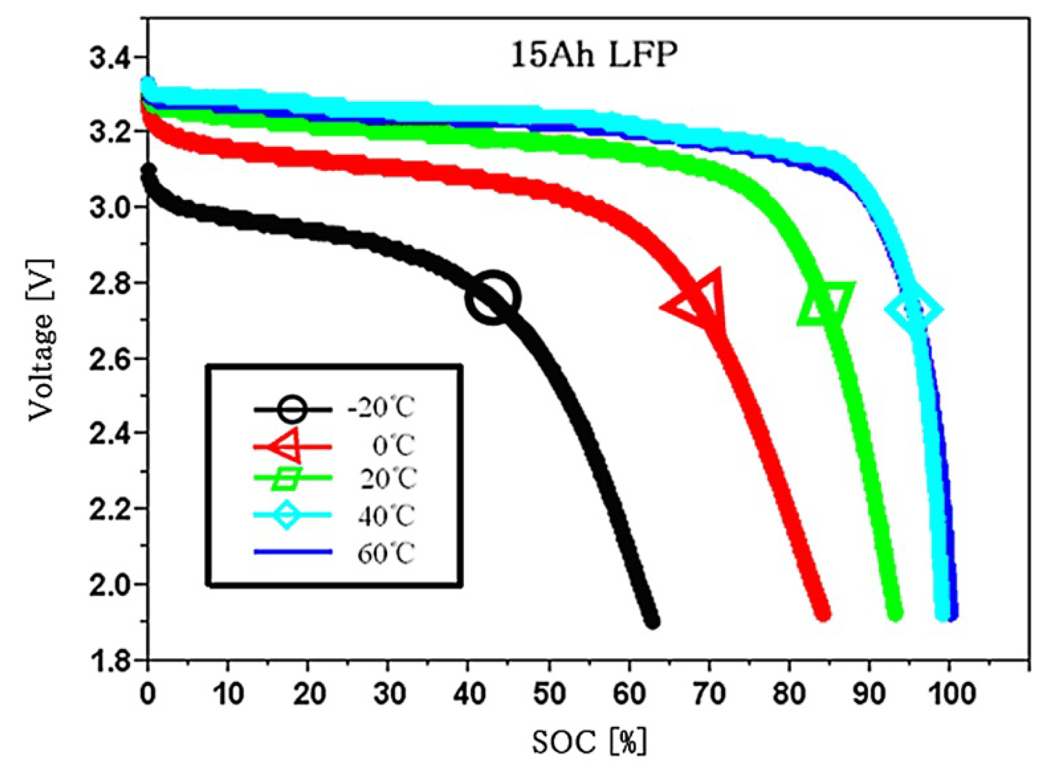
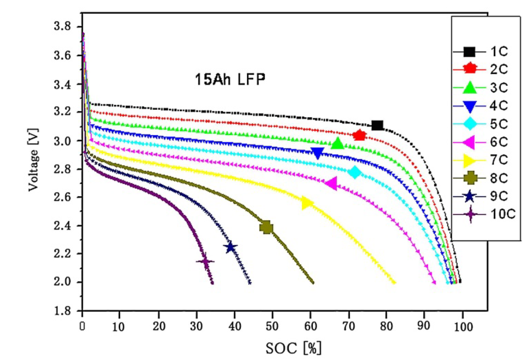
2.3. Model Parameters Determination

The two parameter vectors A and B in the process model can be determined using the least-squares method. A and B are model “parameters” for capturing dependence of battery characteristics on temperature and charging rates. As such they do not depend on temperature and charge/discharge current values. Typically, their values for new batteries can be estimated off-line either by using typical characteristic curves from the manufacturers or individually prior to their usage. In this paper, these parameters are assumed to be pre-determined and used in our SOC estimation schemes. On the other hand, battery aging will cause deviations on battery characteristics and consequently all battery model parameters will change. The issue of system identification for the entire battery model after aging takes effect is of critical importance and was discussed in our earlier papers [18,24], but beyond the scope of this paper. One relevant aspect is that the SOC is relatively insensitive to the parameter variations in A and B, which are shown in Section 3. The parameter vector p in the measurement model should be obtained before SOC estimation, either offline or online. The least-squares method is a suitable offline method, and its recursive version is a common online parameter estimation method. The experimental results in Section 3 demonstrate that both offline and online methods are effective.

3. UKF-Based SOC Estimation

3.1. UKF-Based SOC Estimation

As mentioned before, UKF has been demonstrated to outperform the KF and EKF. It is utilized for SOC estimation in this paper. An interesting work has been reported by He et al. [27], which demonstrated the promising results of applying the UKF in a battery’s SOC estimation. Although our method is also based on the UKF, the main differences between our paper and that of He et al. [27] are that: (1) our paper proposes an enhanced battery model to model the impact of discharge rate and temperature on the Li-ion battery’s performance, as given in Section 2; (2) a UKF-based algorithm is then developed to jointly estimate the battery’s SOC and the internal resistance, which is important to capture the aging effect, as will be discussed in Section 4; (3) the proposed method is realized in an embedded system to further demonstrate the effectiveness of using the UKF in battery characterization, as will be discussed in Section 5.
The battery dynamics lead to the complex measurement model of Equation (8), which may not be very accurate. In contrast, errors inevitably exist when the current and terminal voltage are measured. Therefore, noise items should be included for both the process model and measurement model. Equations (6) and (8) now change to:
Zk+1 = h(Zk, ik) + Sk = Zk − (μΔt/Qn)ik + Sk
yk = g(w, ik, Zk) + vk = K0RikK1/ZkK2Zk + K3lnZk + K4ln(1 − Zk) + vk
Assume the covariance of the process noise Sk to be Rs and the covariance of the measurement noise vk to be Rvk. RSk is highly related to the system noise and current measurement error; and Rvk is highly related to the terminal voltage measurement error.
The SOC is treated as one of the elements of the state vector. To compensate for the possible non-Gaussian property of the noises, the process noise and the measurement noise are included in the state vector as well. The extended state vector xk and its covariance Energies 06 04134 i005 in the UKF-based SOC estimation have the following form:
xk−1 = [Zk−1 0 0]T
Energies 06 04134 i006
The steps of applying the UKF for SOC estimation are summarized below.
Initialization (Actually, the initial state and covariance are not critical to the UKF algorithm; they can converge to the true value quickly. Random values are used here):
Energies 06 04134 i007
For k = 1,2...,∞:
(1) Calculate the weighted sigma points:
Energies 06 04134 i008
where the sigma points are:
Energies 06 04134 i009
Energies 06 04134 i010
Energies 06 04134 i011
with the parameters α, β for the unscented transform given, the parameter λ = α2LL can be calculated and the weights for the sigma points are [28,29]:
Energies 06 04134 i012
Energies 06 04134 i013
Energies 06 04134 i014
The superscripts m and c here indicate that the weights are used for the estimation of the mean and covariance, respectively. Thus, we have Energies 06 04134 i015 and Energies 06 04134 i016. Generally, we can choose 0 ≤ α ≤ 1, β ≥ 0. The weights may be optimally chosen to asymptotically minimize error variances in the sense of the Cramer-Rao lower bound or the maximum-likelihood estimates, when the noise statistics are available. Turner et al. [30] proposed a method to determine optimally of parameters for the UKF under Gaussian noise. For practical systems in which noise characteristics are often unknown, tuning of the weighting is part of the design iteration process. However, the optimal selection of the parameters is outside the scope of this paper; thus, the often-recommended parameters α = 1, β = 0 are used instead. Energies 06 04134 i017 is the i − th column of the square root matrix of the matrix Energies 06 04134 i018.
(2) Time update equations:
Sigma points updating Xk|k-1:
Xk|k-1 = h(Xk-1,uk)
State estimation Energies 06 04134 i019:
Energies 06 04134 i020
Covariance Energies 06 04134 i021 of the estimated state:
Energies 06 04134 i022
(3) Measurement update equations:
Measurement updating Yk|k-1:
Yk|k-1 = g(Xk-1,uk)
Measurement estimation Energies 06 04134 i023:
Energies 06 04134 i024
Covariance Energies 06 04134 i025 of the estimated measurement Energies 06 04134 i026:
Energies 06 04134 i027
Cross-covariance Energies 06 04134 i028 of Xk-1 and Yk|k-1:
Energies 06 04134 i029
Kalman gain Kk:
Energies 06 04134 i030
State update Energies 06 04134 i031:
Energies 06 04134 i032
Covariance Energies 06 04134 i033 of state update Energies 06 04134 i031:
Energies 06 04134 i034

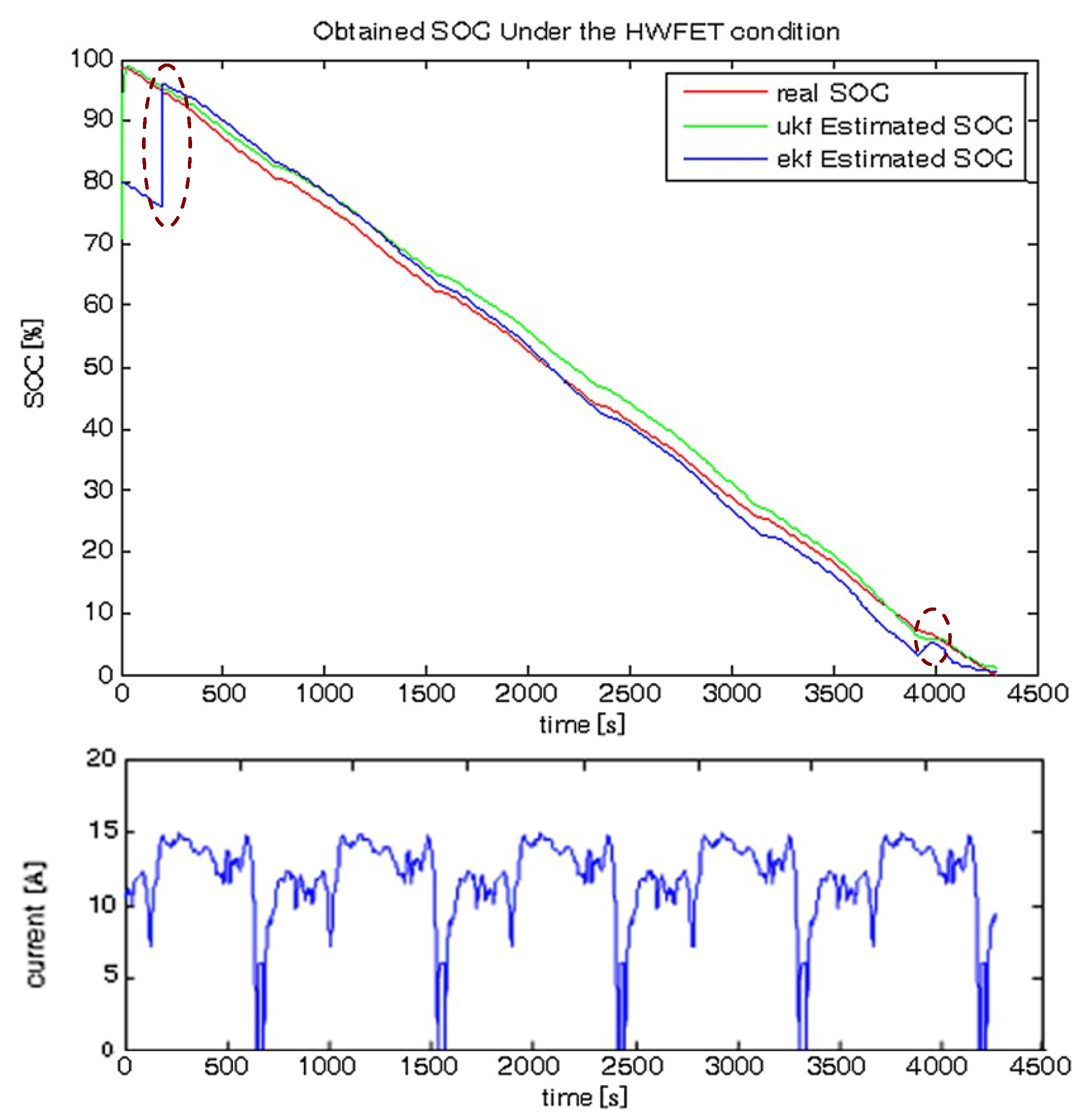
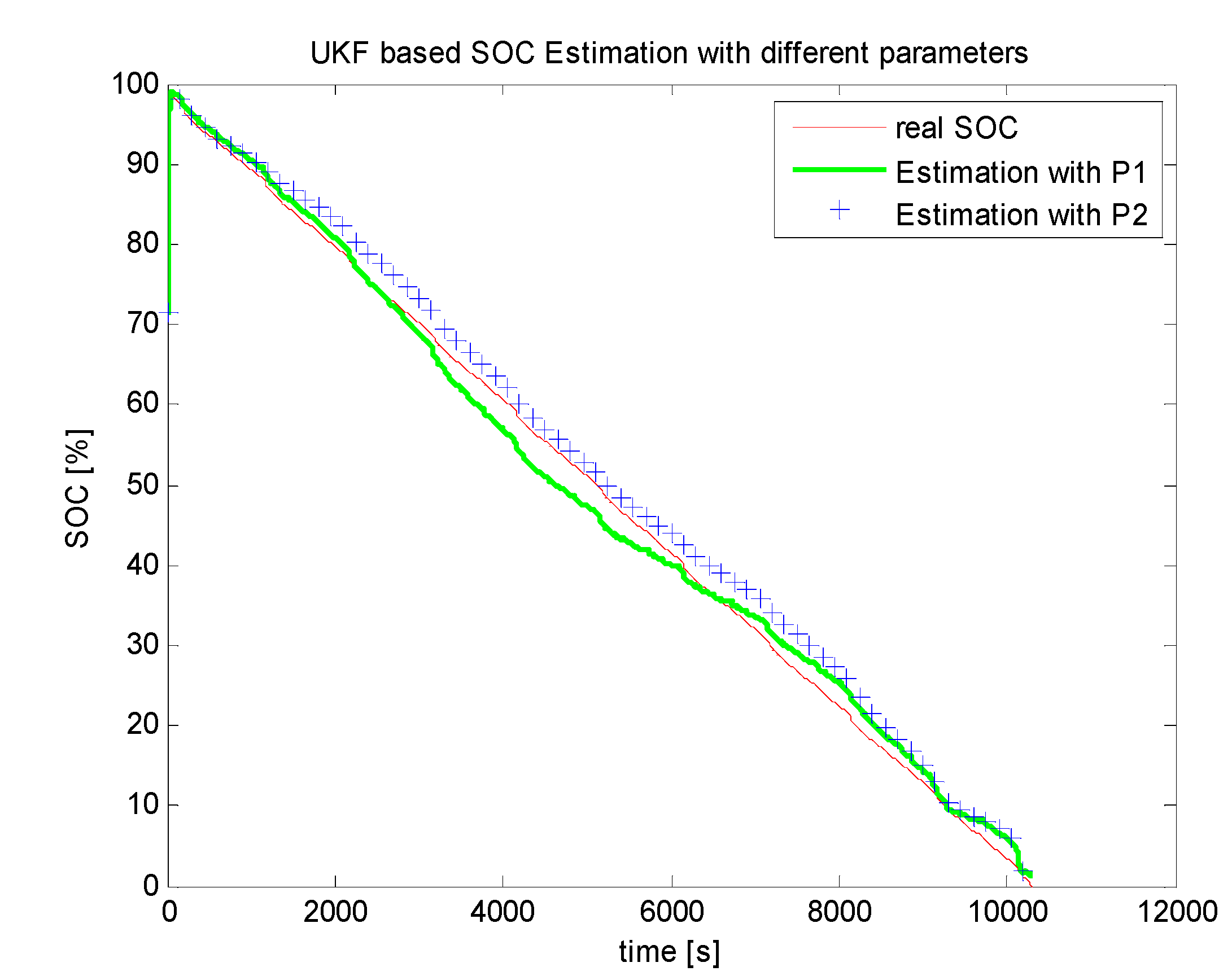
3.2. SOC Estimation Results

The proposed UKF-based SOC estimation algorithm is tested under different simulated test conditions. One of the results under the Highway Fuel Economic Test (HWFET) conditions is shown in Figure 3. The real SOC is obtained by post-processing involving integrating the battery current with time. For comparison, the EKF-based SOC estimation results are also provided. The initial SOC in the UKF-based algorithms is deliberately set to be considerably different than its real value, and the standard covariance of the initial SOC is set to be 0.1. The comparisons are performed across four aspects: the maximum SOC estimation error, average SOC estimation error, SOC estimation mean square error (MSE), and estimation speed. These are listed in Table 1.
Figure 3. SOC estimation under the HWFET condition.
Energies 06 04134 g003
Table 1. Comparisons of the UKF- and EKF-based SOC estimation.
AlgorithmMaximum errorMean errorMean square errorSpeed
UKF5.1%3.8%4.89 × 10−41.49 ms/sample
EKF19.8%5.5%2.1 × 10−32.91 ms/sample
As observed from Table 1, the UKF-based SOC estimation outperforms that based on the EKF. The superiority of the UKF over the EKF can also be observed from the positions marked by the dotted cyan ellipses in Figure 3. The first ellipse on the upper left indicates that the SOC estimated by the EKF needs some time before it can catch up with the real SOC, whereas the UKF estimate converges considerably faster. At the position of the bottom right ellipse, a fluctuation exists in the SOC curve estimated by the EKF, which does not reflect reality when the battery is being discharged. The same problem does not exist for the UKF. The faster speed of the UKF indicates that it is superior to the EKF for embedded applications.
To explore the influence of the measurement model parameters on the accuracy of the estimated SOC based on the UKF, two different sets of parameter vectors obtained by our previously proposed UKF-based parameter estimation method [31] and the least-squares method [32] are applied to the measurement model (10). The SOC estimation results under different parameters are shown in Figure 4. The results indicate that both parameter vectors are effective and that a reasonable small change in the parameters, either caused by parameter estimation error or individual battery diversity, does not prevent the UKF from obtaining a relatively accurate SOC estimation. This conclusion is reasonable because the small disturbance of parameters can be handled very well by the process noise and measurement noise.
Figure 4. Influence of model parameters for UKF-based SOC estimation. The conditions for the two experiments are the same.
Energies 06 04134 g004

4. UKF-Based SOC and Internal Resistance Joint Estimation

One important point is that characteristic variations exist in batteries due to different manufacturing and working processes, even though they may be designed to be the same. These variations will lead to different sets of battery model parameters for different batteries. The aging effect is another important feature of Li-ion batteries. That is, the performance of the battery degrades continuously with time, e.g., the internal resistance increases, and the total energy capacity that can be drawn from the battery decreases. For these reasons, the applied mathematical model (10) should be adjustable so that an accurate SOC estimation can be obtained.
The importance of considering aging effect is shown in Figure 5. The figure presents the SOC estimation results for one of the tested batteries, whose internal resistance changed from 2 to 5 mΩ due to the aging effect after a long working time. As observed from Figure 5, a maximum SOC estimation error larger than 20% exists if the change in the internal resistance was not captured.
One can use an online parameter estimation algorithm, e.g., our previously proposed parameter estimation algorithm [33], to estimate and update the model parameters. Unfortunately, as shown in [33], the parameters converge only after all of the data in an entire discharge process are fed to the UKF-based online estimation algorithm, which makes it inconvenient for real applications. Moreover, it is hard to decide how frequently the parameters should be updated.
Figure 5. UKF-based SOC estimation with/without considering the battery aging effect.
Energies 06 04134 g005
To compensate for the continuous increase of the internal resistance due to the aging effect, we proposed a joint estimation algorithm for the SOC and internal resistance [33]. The algorithm can estimate the SOC and internal resistance simultaneously. The main idea of the algorithm is to treat both the SOC and internal resistance as elements of the state vector, forming a new state vector Energies 06 04134 i035 as follows:
Energies 06 04134 i036
The new process (state transition) equation is now:
Energies 06 04134 i037
whereas the new measurement equation is:
Energies 06 04134 i038
where uk is the input vector Energies 06 04134 i039 and Energies 06 04134 i040 and are process noise and measurement noise, respectively.
In Equations (32) and (33), Energies 06 04134 i041 and Energies 06 04134 i042 are extensions of Equations (9) and (10), respectively. Energies 06 04134 i041 is now defined as follows:
Energies 06 04134 i043
while Energies 06 04134 i042 has the same form as Energies 06 04134 i044 in Equation (10).
With the new defined state vector and the corresponding process model and measurement model, the similar state estimation algorithm in Section 3.1 can be applied to estimate the SOC and internal resistance simultaneously.
The jointly estimated SOC and internal resistance with the UKF are shown in Figure 6. The joint estimation result using the EKF is also shown in the figure for comparison. The real values of the internal resistance are obtained with the HIOKI 3554 battery test equipment made by HIOKI E.E Corporation (Nagano, Japan).
Figure 6. Joint estimation of the SOC and internal resistance. (a) Jointly estimated SOC; (b) Jointly estimated internal resistance.
Energies 06 04134 g006
As shown in Figure 6, the proposed UKF-based SOC and internal resistance joint estimation algorithm are effective. The processes of SOC and internal resistance estimation converge very fast. Both the estimated SOC and estimated internal resistance according to the UKF algorithm outperform the EKF-based algorithm. For the internal resistance estimation in particular, the EKF-based algorithm fluctuates considerably and even yields negative values of resistance, whereas the UKF does not have such problems. To clearly illustrate the results, the labels of the y-axes in the two sub-figures of Figure 6b are deliberately set to be different; the unit of the internal resistance for the EKF-based algorithm is Ohm (Ω) because of the large estimation fluctuation, whereas the unit of the internal resistance for the UKF-based algorithm is milli-Ohm (mΩ).

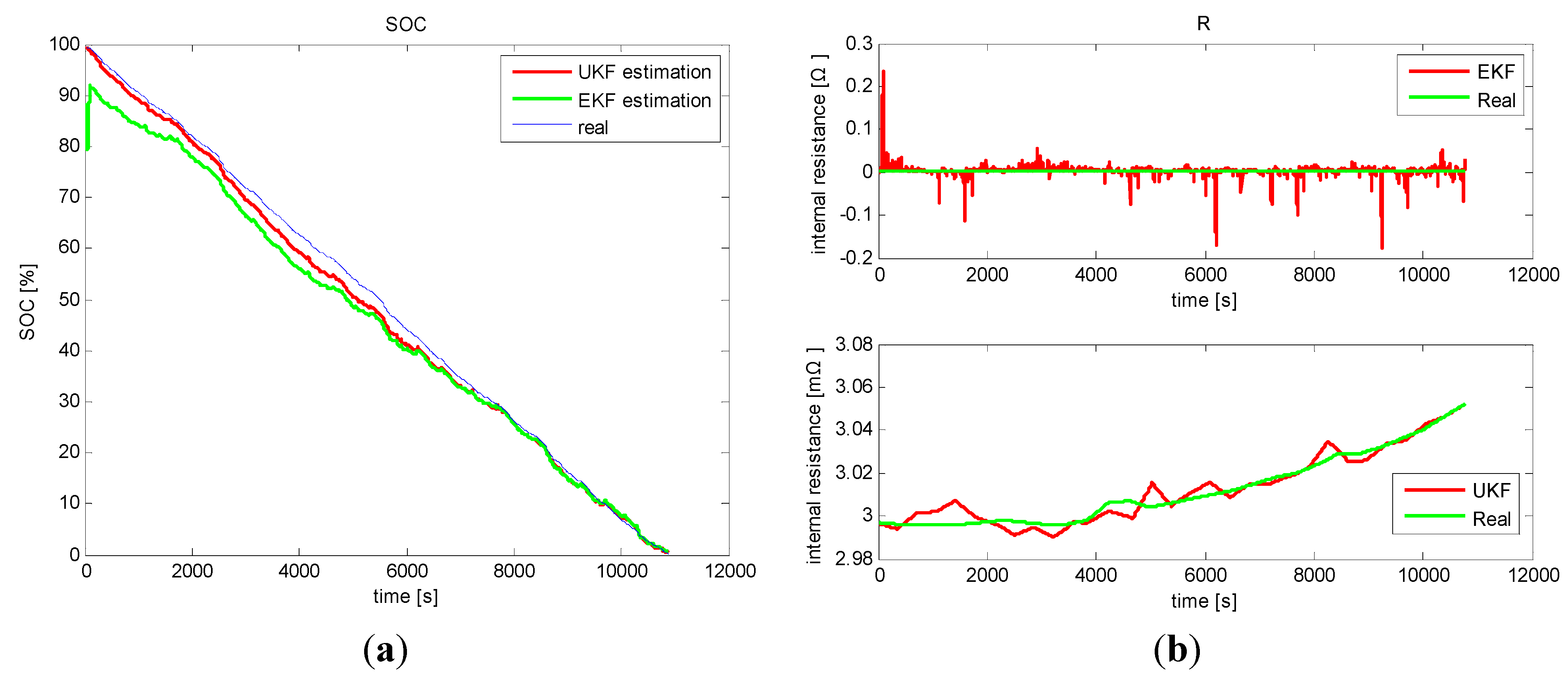
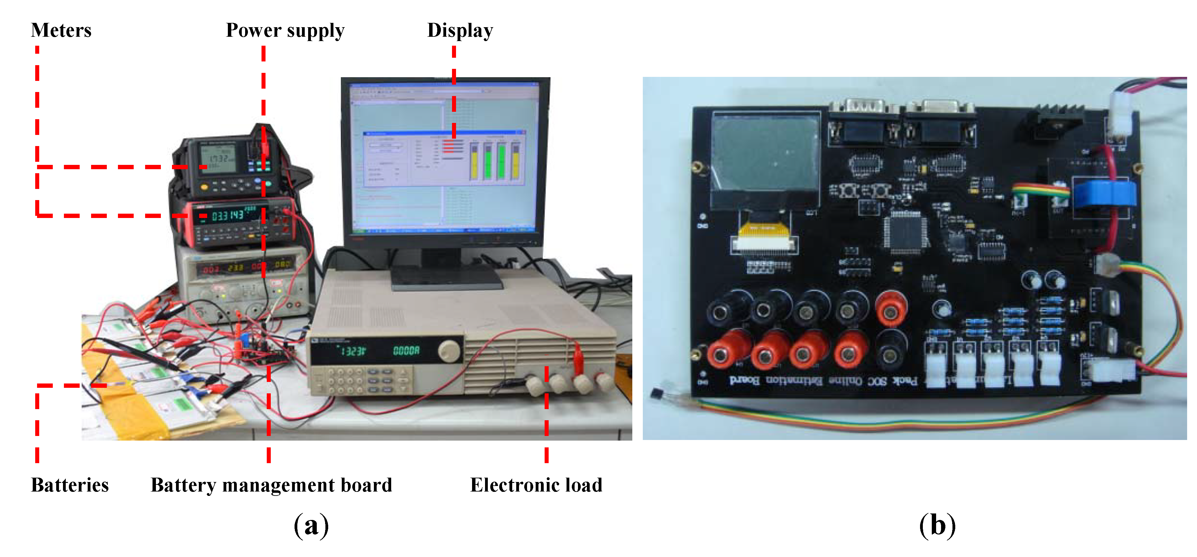
5. Experimental Verification

5.1. System Setup

The proposed algorithms have been verified by the experimental battery management system based on an embedded system. The entire experimental battery SOC estimation system and its setup are shown in Figure 7. The system is mainly composed of the following parts: the core battery management board, batteries, electronic load, power supply, and display, as shown in Figure 7a. The core battery management board was designed by the authors and is shown in Figure 7b. This board measures the voltages, currents, and temperatures of batteries, and then uses these parameters to estimate the SOC of each battery. The data are sampled every 1 s. The system can be used to estimate the SOCs for four batteries simultaneously, as shown in Figure 7. The system can be extended with an enhanced microcontroller unit to estimate SOCs of additional batteries simultaneously.
Several different types of Li-ion batteries made by different manufacturers with different chemistry are utilized in the experiments. The nominal capacities of the batteries also differ. Some of the tested battery types are listed in Table 2.
Figure 7. Experimental battery SOC estimation system. (a) System setup; (b) Developed battery management board.
Energies 06 04134 g007
Table 2. Tested types of Li-ion batteries.
Type #ChemistryNominal voltage (V)Nominal capacity (Ah)Manufacturer
1LiFePO43.215Wan Xiang
2Li-Mn3.710Yi Mao
3LiFePO43.250Yi Mao

5.2. Algorithm and Model Verification

The proposed method is first verified with an alternating discharge/charge profile, as shown in Figure 8. As observed from Figure 8, the difference between the estimated SOC and the real SOC is relatively small.
The importance of temperature consideration is then examined, as shown in Figure 9. The battery is deliberately put into a thermal chamber whose temperature is set to 0 °C. The battery is then discharged under the HWFET condition, as shown in Figure 3, and the data are recorded for SOC estimation. During the SOC estimation process, the temperature information is deliberately discarded, and it is assumed to be at a constant room temperature of 25 °C. As observed from Figure 9, large errors of SOC estimation occur when the temperature information is discarded. The maximum SOC estimation error exceeds 20% (this is an absolute error, not a relative error). In contrast, the estimation accuracy is acceptable when the SOC is estimated according to the enhanced battery model (9) with the true temperature.
Figure 8. SOC estimation with an alternating discharge/charge profile.
Energies 06 04134 g008
Figure 9. Importance of temperature consideration for UKF-based SOC estimation. When temperature information is discarded, large errors occur.
Energies 06 04134 g009
The importance of considering the discharge rate is examined in a similar manner. For this experiment, the battery is discharged at a constant discharge rate of 8 C. During the SOC estimation process, an absolute SOC estimation error of 45% is obtained if the discharge rate information is deliberately discarded and is assumed to be 1 C. In contrast, the estimation is accurate if the SOC is estimated according to the enhance battery model (9) with the proper discharge rate.
The proposed enhanced model is further validated under different discharge rates and working temperatures. Figure 10 presents the predicted voltages when the battery is discharged with different discharge rates (the envelope of the current waveform is similar to that of Figure 3, but the maximum discharge rate is now 8 C) at 50 °C. As observed from Figure 10, the measured voltages encounter both smooth segments and sharp changes. In both cases, the predicted terminal voltages on the basis of the estimated SOC can track the true voltages with high accuracy. Similar results are obtained for other temperatures with varying currents.
Figure 10. Model validation when the battery is discharged at 50 °C, with a varying maximum discharge rate of 8 C. (a) The real and predicted voltages in a entire discharging process; (b) An enlarged view of the middle part.
Energies 06 04134 g010

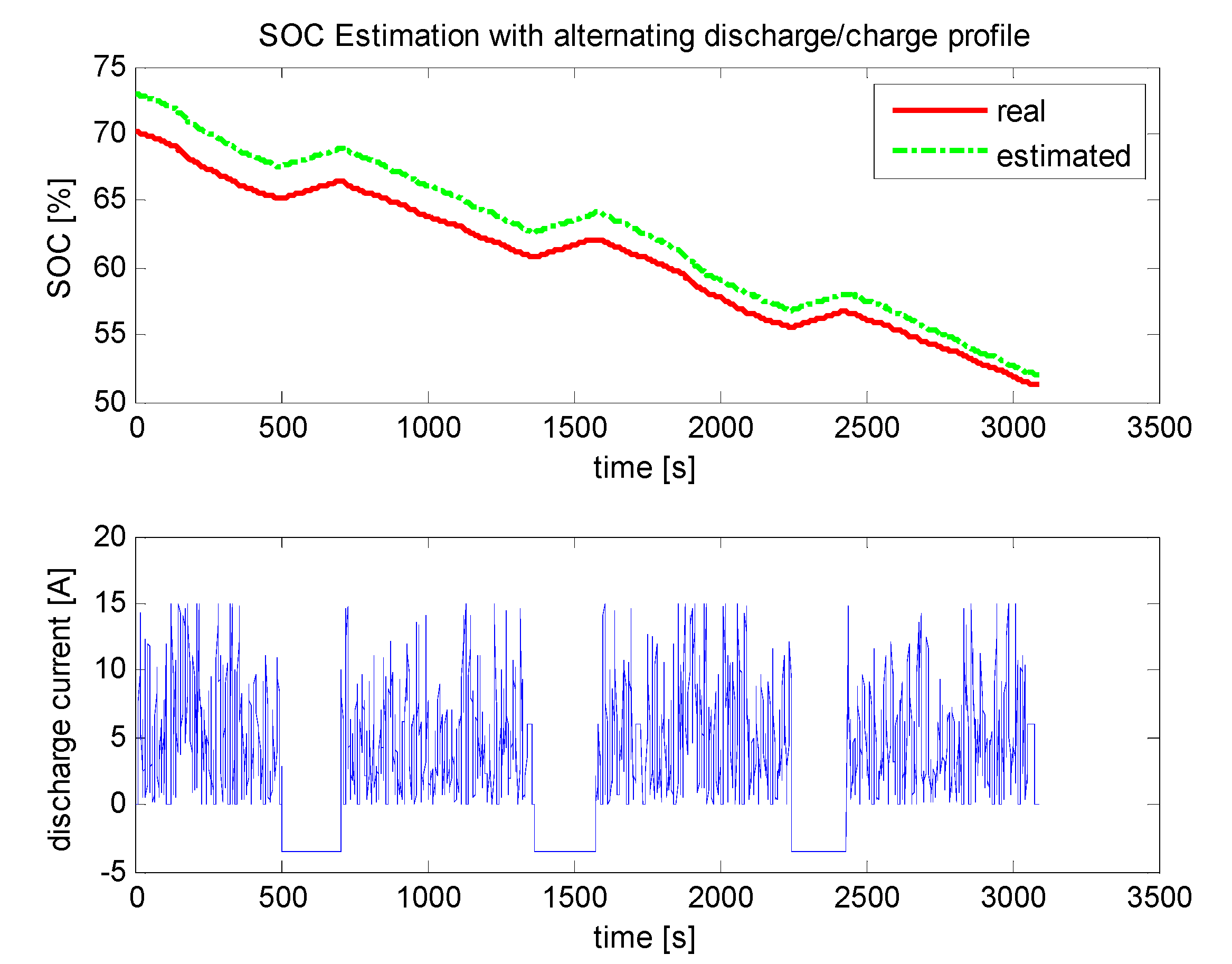
5.3. Battery Chemistry Adaptability

Previous results are obtained with the type #1 battery, but similar results can be obtained for other types of batteries. An example SOC estimation result for a type #2 battery under the Federal Urban Driving Schedule (FUDS) [34] test condition is shown in Figure 11. As observed from the figure, the estimation is accurate, which indicates that the proposed algorithms are suitable for these types of Li-ion batteries.
Figure 11. SOC estimation results for the type #2 battery under the FUDS condition.
Energies 06 04134 g011

6. Conclusions

This paper proposes an unscented Kalman filter algorithm for online battery SOC estimation when the battery is discharged. An enhanced battery model was developed first to make the algorithm suitable for real-time battery characterization under different operating conditions, particularly under different temperatures and discharge rates. An SOC and internal resistance joint estimation method was proposed to lay the foundation for the online battery SOC estimation and to compensate for the battery aging effect. The UKF-based adaptive SOC estimation algorithm was tested for different types of batteries. The experimental results indicate that the proposed algorithm is effective in battery SOC estimation and is suitable for online, embedded applications. One of our future tasks will be to develop a similar model for the charging process. With dedicated, separate models for the charging and discharging processes of Li-ion batteries, the performance of the corresponding joint SOC estimation algorithm should then be investigated with complicated charge/discharge current profiles.

Acknowledgments

The authors would like to thank the anonymous reviewers for their insightful comments and suggestions. This work was supported by the Nature Science Foundation of China (NSFC) Grant #60871088, #61001216, and #61172132, Zhejiang Provincial Natural Science Foundation of China Grant #Z1110741, #LQ13F010011, Zhejiang Educational Committee Foundation of China Grant #Z201122745. The work of Caisheng Wang and Leyi Wang was supported in part by the National Science Foundation of USA under grant ECCS-1202133.

Conflict of Interest

The authors declare no conflict of interest.

References

  1. Larico, H.R.E.; Barbi, I. Three-phase push–pull DC–DC converter: Analysis, design, and experimentation. IEEE Trans. Ind. Electron. 2012, 12, 4629–4636. [Google Scholar] [CrossRef]
  2. Kutluay, K.; Çadırcı, Y.; Özkazanç, Y.S. A new online state-of charge estimation and monitoring system for sealed lead-acid batteries in telecommunication power supplies. IEEE Trans. Ind. Electron. 2005, 5, 1315–1327. [Google Scholar] [CrossRef]
  3. Hu, Y.; Yurkovich, S. Battery State of Charge Estimation in Automotive Applications Using LPV Techniques. In Proceedings of 2010 American Control Conference, Baltimore, MD, USA, 30 June–2 July 2010.
  4. Amjadi, Z.; Williamson, S.S. Power-electronics-based solutions for plug-in hybrid electric vehicle energy storage and management systems. IEEE Trans. Ind. Electron. 2010, 2, 608–616. [Google Scholar] [CrossRef]
  5. Ma, C.; Yang, Y. A battery-aware scheme for routing in wireless ad hoc networks. IEEE Trans. Ind. Electron. 2011, 8, 3919–3932. [Google Scholar]
  6. Shahriairi, M.; Farrokhi, M. On-line state of health estimation of VRLA batteries using state of charge. IEEE Trans. Ind. Electron. 2013, 1, 191–202. [Google Scholar] [CrossRef]
  7. Yuan, S.; Wu, H.; Yin, C. State of charge estimation using the extended Kalman filter for battery management systems based on the ARX battery model. Energies 2013, 6, 444–470. [Google Scholar] [CrossRef]
  8. Urbain, M.; Raël, S.; Davat, B.; Desprez, P. State Estimation of a Lithium-Ion Battery through Kalman Filter. In Proceedings of IEEE Power Electronics Specialists Conference, Orlando, FL, USA, 17–21 June 2007.
  9. Plette, G.L. Extended Kalman filtering for battery management systems of LiPB-based HEV battery packs: Part 2. J. Power Sources 2004, 2, 262–276. [Google Scholar] [CrossRef]
  10. Plette, G.L. Sigma-point Kalman filtering for battery management systems of LiPB-based HEV battery packs. Part 2: Simultaneous state and parameter estimation. J. Power Sources 2006, 2, 1369–1384. [Google Scholar] [CrossRef]
  11. Zhang, F.; Liu, G.; Fang, L.; Wang, H. Estimation of battery state of charge with H-infinity observer: Applied to a robot for inspecting power transmission lines. IEEE Trans. Ind. Electron. 2012, 2, 1086–1095. [Google Scholar] [CrossRef]
  12. Lee, Y.-S.; Wang, W.-Y.; Kuo, T.-Y. Soft computing for battery state-of-charge (BSOC) estimation in battery string systems. IEEE Trans. Ind. Electron. 2008, 1, 229–239. [Google Scholar] [CrossRef]
  13. Li, S.G.; Sharkh, S.M.; Walsh, F.C.; Zhang, C.N. Energy and battery management of a plug-in series hybrid electric vehicle using fuzzy logic. IEEE Trans. Veh. Technol. 2011, 8, 3571–3585. [Google Scholar] [CrossRef]
  14. Knauff, M.; Dafis, C.; Niebur, D. A New Battery Model for Use with an Extended Kalman Filter State of Charge Estimator. In Proceedings of 2010 American Control Conference, Baltimore, MD, USA, 30 June–2 July 2010.
  15. Smith, K.A.; Rahn, C.D.; Wang, C.Y. Control oriented 1D electrochemical model of Lithium-ion battery. Energy Convers. Manag. 2007, 9, 2565–2578. [Google Scholar] [CrossRef]
  16. Bhangu, B.S.; Bentley, P.; Stone, D.A.; Bingham, C.M. Nonlinear observers for predicting state-of-charge and state-of-health of lead-acid batteries for hybrid-electric vehicles. IEEE Trans. Veh. Technol. 2005, 3, 783–794. [Google Scholar] [CrossRef]
  17. Coleman, M.; Lee, C.K.; Zhu, C.; Hurley, W.G. State-of-charge determination from EMF voltage estimation: Using impedance, terminal voltage, and current for lead-acid and lithium-ion batteries. IEEE Trans. Ind. Electron. 2007, 5, 2550–2557. [Google Scholar] [CrossRef]
  18. Sitterly, M.; Wang, L.Y.; Yin, G.; Wang, C. Enhanced identification of battery models for real-time battery management. IEEE Trans. Sustain. Energy 2011, 3, 300–308. [Google Scholar] [CrossRef]
  19. Kim, T.; Qiao, W. A hybrid battery model capable of capturing dynamic circuit characteristics and nonlinear capacity effects. IEEE Trans. Energy Conv. 2011, 4, 1172–1180. [Google Scholar] [CrossRef]
  20. Chen, L.-R.; Liu, C.-S.; Chen, J.-J. Improving phase-locked battery charger speed by using resistance-compensated technique. IEEE Trans. Ind. Electron. 2009, 4, 1205–1211. [Google Scholar] [CrossRef]
  21. Agarwal, V.; Uthaichana, K.; DeCarlo, R.A.; Tsoukalas, L.H. Development and validation of a battery model useful for discharging and charging power control and lifetime estimation. IEEE Trans. Energy Conv. 2010, 3, 821–835. [Google Scholar] [CrossRef]
  22. Carter, R.; Cruden, A.; Hall, P.J.; Zaher, A.S. An improved lead-acid battery pack model for use in power simulations of electric vehicles. IEEE Trans. Energy Conv. 2012, 1, 21–28. [Google Scholar] [CrossRef]
  23. Klein, R.; Chaturvedi, N.A.; Christensen, J.; Ahmed, J.; Findeisen, R.; Kojic, A. State Estimation of a Reduced Electrochemical Model of a Lithium-Ion Battery. In Proceedings of 2010 American Control Conference, Baltimore, MD, USA, 30 June–2 July 2010.
  24. Liu, L.; Wang, L.Y.; Chen, Z.; Wang, C.; Lin, F.; Wang, H. Integrated system identification and state-of-charge estimation of battery systems. IEEE Trans. Energy Conv. 2013, 1, 12–23. [Google Scholar] [CrossRef]
  25. Xing, Y.; Ma, E.W.M.; Tsui, K.L.; Pecht, M. Battery management systems in electric and hybrid vehicles. Energies 2011, 4, 1840–1857. [Google Scholar] [CrossRef]
  26. He, W.; Williard, N.; Osterman, M.; Pecht, M. Prognostics of lithium-ion batteries based on Dempster–Shafer theory and the Bayesian Monte Carlo method. J. Power Sources 2011, 196, 10314–10321. [Google Scholar] [CrossRef]
  27. He, W.; Williard, N.; Chen, C.; Pecht, M. State of charge estimation for electric vehicle batteries using unscented kalman filtering. Microelectron. Reliab. 2013, 53, 840–847. [Google Scholar] [CrossRef]
  28. Julier, S.J.; Uhlmann, J.K.; Durrant, W.H.F. A New Approach for Filtering Nonlinear Systems. In Proceedings of the American Control Conference, Seattle, WA, USA, 21–23 June 1995.
  29. Van der Merwe, R. Sigma-Point Kalman Filters for Probabilistic Inference in Dynamic State-Space Models. Ph.D. Thesis, Oregon Health & Science University, Portland, OR, USA, 2004. [Google Scholar]
  30. Turner, R.; Rasmussen, C.E. Model Based Learning of Sigma Points in Unscented Kalman Filtering. In Proceedings of Machine Learning for Signal Processing, Kittilä, Finland, 29 August–1 September 2010.
  31. He, Z.; Gao, M.; Xu, J.; Liu, Y. Battery Model Parameters Estimation with the Sigma Point Kalman Filter. In Proceedings of 2009 International Conference on Artificial Intelligence and Computational Intelligence, Shanghai, China, 7–9 November 2009.
  32. Haykin, S.O. Adaptive Filter Theory, 4th ed.; Prentice Hall: Englewood Cliffs, NJ, USA, 2001. [Google Scholar]
  33. He, Z.; Liu, Y.; Gao, M.; Wang, C. A Joint Model and SOC Estimation Method for Lithium Battery Based on the Sigma Point KF. In Proceedings of 2012 IEEE Transportation Electrification Conference and Expo, Dearborn, MI, USA, 18–20 June 2012.
  34. Dynamometer Driving Scheules Utilized at the National Vehicle and Fuel Emissions Laoratory. Available online: http://www.epa.gov/nvfel/testing/dynamometer.htm (accessed on 12 June 2012).

