Article

Numerical Simulation on Head-On Binary Collision of Gel Propellant Droplets

College of Aerospace Science and Engineering, National University of Defense Technology, 109 Deya Road, Changsha 410073, China
*
Author to whom correspondence should be addressed.
Energies 2013, 6(1), 204-219; https://doi.org/10.3390/en6010204
Submission received: 15 November 2012 / Revised: 25 December 2012 / Accepted: 26 December 2012 / Published: 8 January 2013

Abstract

:
Binary collision of droplets is a fundamental form of droplet interaction in the spraying flow field. In order to reveal the central collision mechanism of two gel droplets with equal diameters, an axi-symmetric form of the Navier-Stokes equations are firstly solved and the method of VOF (volume of fluid) is utilized to track the evolution of the gas-liquid free interface. Then, the numerical computation model is validated with Qian’s experimental results on Newtonian liquids. Phenomena of rebound, coalescence and reflexive separation of droplets after collision are investigated, and structures of the complicated flow fields during the collision process are also analyzed in detail. Results show that the maximum shear rate will appear at the point where the flow is redirected and accelerated. Rebound of droplets is determined by the Weber number and viscosity of the fluid together. It can be concluded that the gel droplets are easier to rebound in comparison with the base fluid droplets. The results also show that the alternant appearance along with the deformation of droplets in the radial and axial direction is the main characteristic of the droplet coalescence process, and the deformation amplitude attenuates gradually. Moreover, the reflexive separation process of droplets can be divided into three distinctive stages including the radial expansion, the recovery of the spherical shape, and the axial extension and reflexive separation. The variation trend of the kinetic energy is opposite to that of the surface energy. The maximum deformation of droplets appears in the radial expansion stage; in the case of a low Weber number, the minimum central thickness of a droplet appears later than its maximum deformation, however, this result is on the contrary in the case of a high Weber number.

1. Introduction

Droplet collision exists widely and plays an elementary role in various spraying combustion processes of power equipment (aero engine, internal-combustion engine, and liquid rocket engine). The collision outcome affects the atomization characteristics, and substantially influences the subsequent combustion performance, because of the dependence of the vaporization and combustion of droplets on the droplet size, according to the well-known d2-law. Extensive numerical and experimental work has been carried out for Newtonian fluids in the past, in order to improve atomization characteristics and combustion efficiency [1]. However, conventional liquid and solid propellants cannot meet the demands of future high performance and improved safety rocket launchers, and the gel propellant seem to be a promising answer to these requirements by combining the advantages of both and neglecting the maximum number of disadvantages at the same time [2,3,4,5,6]. However, one serious problem is that the gels’ viscosity increases with addition of gelling agents which change the fuel into a non-Newtonian fluid, making it more difficult to atomize. Droplet collisions can significantly modify the spray process and combustion characteristics [1]. Due to the increased rheological complexity, studies have so far been mainly limited to Newtonian fluids. Therefore, it is essential to conduct investigations on gel propellant droplet collision.
Newtonian fluid droplet collision has been investigated both experimentally and numerically for decades. Experimental studies have showed that outcome of droplet collision mainly depends on the droplet diameter D1, D2 (D1D2), the initial relative velocity ur, the surface tension σ, the density ρl and viscosity μl of the liquid as well as the perpendicular distance X (Figure 1) between the two lines passing through the droplet centres with direction parallel to the droplet relative velocity [7,8].
Figure 1. Schematic of binary droplet collision.
Energies 06 00204 g001
These variables are grouped into three important dimensionless parameters in binary droplet collision: Weber (We) number and Reynolds (Re) number, and impact parameter (B), which are defined as follows:
We = ρ l u r 2 D 1 / σ
Re = ρ l u r D 1 / μ l
B = 2 X / ( D 1 + D 2 )
where B = 0 and B = 1 respectively designate head-on and grazing collisions.
Since most fuels are Newtonian fluids, experimental studies on droplet collision are mainly limited to such fluid [9,10,11,12,13]. Ashgriz and Poo [9] performed extensive experiments to interpret water droplet collision mechanisms, and obtained a transition curve between coalescence and separation regimes based on collision outcome. Brenn and Frohn [10] studied the collision and merging of two droplets of propanol-2, water and n-hexadecane. Qian and Law [11] conducted experimental studies of the binary droplet collision dynamics, with emphasis on the transition between different collision outcomes. Five distinct collision outcome regimes (coalescence after minor deformation, bouncing, coalescence after substantial deformation, coalescence followed by separation for near head-on collision, and coalescence followed by separation for off-center collision) were identified. Gotaas et al. [12] have studied the effects of viscosity on droplet-droplet collision outcome. The dynamics of head-on collision between two identical droplets was experimentally and computationally investigated by Pan et al. [13], who emphasized on the transitions from merging to bouncing and to merging again as Weber number increases. Although experimental studies can monitor the evolution of the complex collision geometry by employing fast-speed digital cameras, the flow processes inside the drops can hardly be accessed. Numerical investigations can produce much more details of the local phenomena including the velocity and pressure fields inside the droplets, which are more important to reveal mechanisms of droplet collision [14].
For numerical simulations of binary droplet collisions, several numerical methods have been used for tracking the liquid-gas interface, including the Marker-And-Cell (MAC) method, the front tracking method, Lattice Boltzmann (LB) method, Level-Set (LS) method, Smoothed Particle Hydrodynamic (SPH) method and VOF method [7,8,12,13,14,15,16,17,18,19,20]. Dupuy et al. [15] have simulated the binary head-on collisions at high pressure using the LB method, and explained the stochastic behavior of low inertia coalescence at high pressure. The VOF methodology with high accuracy and low the computational cost has been successfully applied by Nikolopoulos et al. [16,18,19] to study the binary collisions of Newtonian fluid droplets, and good agreement was achieved between their simulations and the experimental results of Qian and Law [11]. Chen et al. [7,8] predicted the droplet behavior after collision using an improved volume-of-fluid (VOF) technique, and adaptive mesh refinement (AMR) algorithm, analyzed detailed physics of droplet interaction and mass transfer process. Dai and Schmidt [20] used a three-dimensional moving-mesh unstructured finite-volume solver to investigate the effect of viscosity on the maximum deformation amplitude.
Focke and Bothe [14] conducted computational analysis on binary collision of shear-thinning droplets, but they only investigated the flow field inside the droplets during the process of coalesced fluid radial expansion. In the present work, central collisions of two gel propellant droplets with equal size are investigated numerically. VOF (volume of fluid) method is utilized to track the evolution of the gas-liquid free interface. Phenomena of rebound, coalescence and reflexive separation of two droplets after collision are investigated, and the structure of the complicated flow fields during the collision process is also analyzed in detail.

2. Model Description

Hirt and Nichols [21] firstly introduced the Volume of Fluid (VOF) method to track the evolution of the gas-liquid free interface. The VOF methodology has become a popular method in free interface models used in CFD computational programs, due to high accuracy and low computational cost.

2.1. Mathematical Formulation

The incompressible, transient flows, negligible thermal transfer, the continuity equation can be written as:
ρ t + ( ρ U ) = 0
The momentum equation with surface tension can be written as:
ρ ( U t + U U ) = p + ( 2 μ D ) + F s
where, U = ( u , v ) is the fluid velocity, μ is the dynamic viscosity, ρ is the fluid density. Following the continuum surface force (CSF) model [7] of Brackbill et al. F s is equal to σ κ ( a ) , where σ is the surface tension, κ and a are the curvature and normal to the interface, respectively. D is the deformation tensor, and can be defined as:
D i j = 1 2 ( u i x j + u j x i )
A VOF function f is introduced to track the evolution of the gas-liquid free interface, can be defined as:
f = { 0 ​​​​​                                                           outside droplet 0 < f < 1                    gas/liquid interface 1                                                            inside droplet
According f, the density and viscosity of each cell of computational mesh can be defined as:
ρ = f ρ l + ( 1 f ) ρ g
μ = f μ l + ( 1 f ) μ g
where, the subscript g and l represent gas-phase and liquid-phase respectively.
According to mass continuity, the advection equation for the density can then be written as an equivalent advection equation for the volume fraction:
f t + ( f U ) = 0
Since the simulation of two equal-sized spherical droplets collision is axisymmetric about the X axis, we only need to solve the two-dimensional, axi-symmetric form conservative equations, in order to reduce computational cost. Figure 2 shows the schematic of the setup. Physically, two equal-sized spherical liquid droplets are impulsively started in a quiescent gaseous ambient, both droplets have identical diameter D0 and initial velocity u0. At r = 0, symmetry boundary conditions are imposed, whilst the normal gradient is equal to 0 for the other boundaries. The right half is used as the computational domain to investigate droplet bounding and coalescence (Figure 2a). Due to the high radial deformation during droplet reflexive separation, the upper right quadrant is used as the computational domain to reduce computational cost (Figure 2b).
Figure 2. The physical problem and the computational domain. The size of the computational domain (a) and (b) are 0.3 mm × 1.0 mm and 0.8 mm × 0.5 mm, respectively.
Energies 06 00204 g002

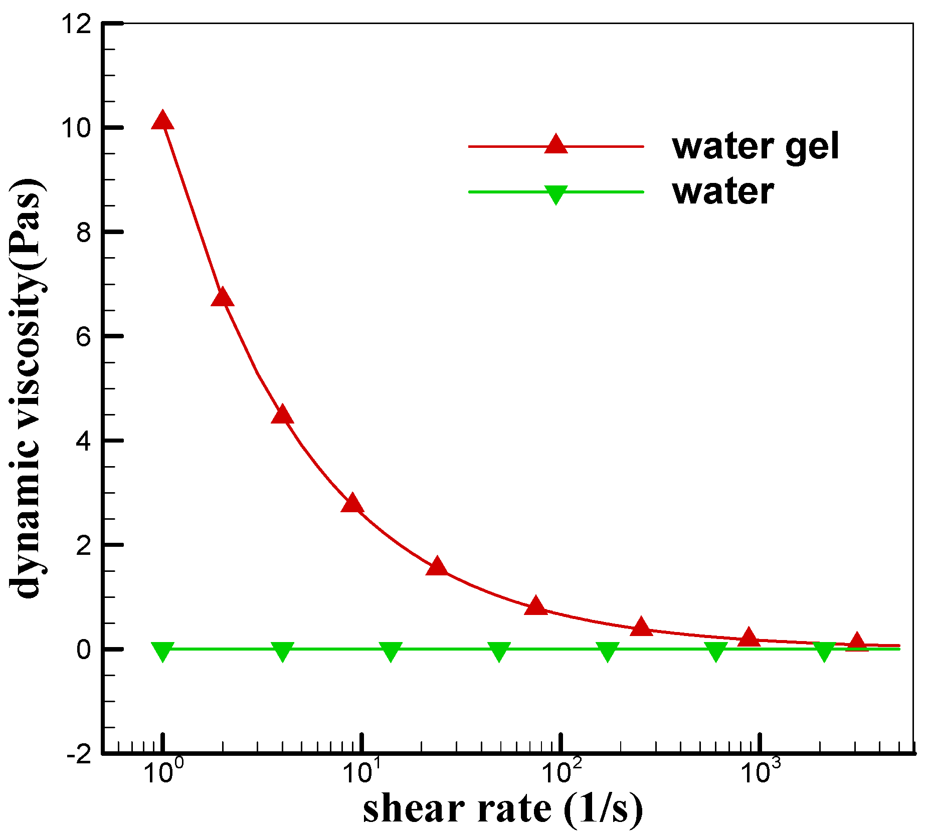
2.2. Gel Propellant Rheology

The simulant gels were used in the present investigation, and were formulated by dissolving Carbopol in water with a mass fraction of 0.3 wt %. The physical properties of the simulant gels (non-Newtonian fluids) are from [22]. The power-law model is used to describe dynamic viscosity, the correction is as follows:
μ = K γ ˙ n 1
where γ ˙ is the rate of stain, K is the consistency index (K = 10.1 Pa·sn), whereas n gives the power-law index of the fluid (n = 0.41), Figure 3 represents the shear rate dependence of dynamic viscosity of water based simulants and water. With increasing shear rate, viscosity of water based simulants tends towards water. The surface tension σ is 0.071 N·m−1, the density ρ is 1,000 kg·m−3.
For Newtonian fluid droplet collision, the two nondimensional parameters (We and Re) have been defined [Equations (1) and (2)]. For power-law model fluid, the effective viscosity is given by Equation (11). γ ˙ is approximated as: γ ˙ = 2 u 0 / D 0 , and by substituting it to Equation (11), we have:
μ = K ( 2 u 0 / D 0 ) n 1
Substituting Equation (12) into Equation (2), we have the modified Reynolds number:
Re = ρ l ( 2 u 0 ) 2 n D 0 n / K
Figure 3. Semi-log plot of the viscosity of water based simulants and water.
Energies 06 00204 g003

3. Model Validations

The solution of the Navier–Stokes equations for droplet collision has to be validated. We carried out two test cases, one to check the gas/liquid interface motion for Newtonian fluid and the other to check the coalesced fluid radial expansion for shear-thinning fluid. In both cases, numerical simulations are to be compared to experimental results.

3.1. Newtonian Droplet Coalescence

In order to test the gas/liquid interface motion for Newtonian fluid droplet coalescence, the calculation conditions are consistent with experimental conditions (Tetradecane droplets in nitrogen environment at atmospheric pressures. We = 32.8, Re = 210.8, B = 0.08, D0 = 318 μm). Figure 4 compares the simulation results with experimental data [11]. The results were coincident with the experimental image, indicating the VOF method is capable of predicting the detail of Newtonian fluid droplet collision.
Figure 4. Sequence of coalescence collision: (a) Present numerical simulation; (b) Obtained by experiment in [11].
Energies 06 00204 g004

3.2. Shear-Thinning Droplet Collision

In order to validate the numerical method for shear dependent viscosity fluid droplet collision, the central binary collisions of 2.8 wt % CMC solution two droplets were studied to check the coalesced fluid radial expansion; the calculation conditions are consistent with experimental conditions. Figure 5 shows that the numerical results agree reasonably well with the corresponding experimental data from [14].
Figure 5. Dimensionless diameter of collision vs. dimensionless time for CMC solution (2.8 wt %): experiment versus simulation. Conditions: D0 = 300 μm, u0 = 5 m/s.
Energies 06 00204 g005

3.3. Grid and Time Step Independence Study

The grid and time step independence are important for tracking the liquid-gas interface, the central binary collisions of shear dependent viscosity fluid droplet was selected for the grid and time step independence study (the calculation conditions are from [14] and consistent with experimental conditions). Four different fine grids with cell size equal to D0/100, D0/300, D0/400, and D0/500 were used for simulation, respectively. Comparing to grids with cell size equal to D0/300, D0/400, and D0/500, the result of grid with cell size equal to D0/100 showed slightly large difference in dimensionless diameter and evolution of droplet shape, however, results of fine grids with cell size equal to D0/300, D0/400, and D0/500 were almost identical (difference in the dimensionless diameter is less than 1%), and agreed well with experimental data. The adaptive time step was used for simulation; the simulation was run using the minimum time step equal to 1.0 × 10⁻⁹ s and 1.0 × 10⁻¹⁰ s, respectively. The results were almost same. Consequently, the grids with cell size equal to D0/300 and the minimum time step equal to 1.0 × 10⁻⁹ s were utilised for the present investigations.

4. Results and Discussion

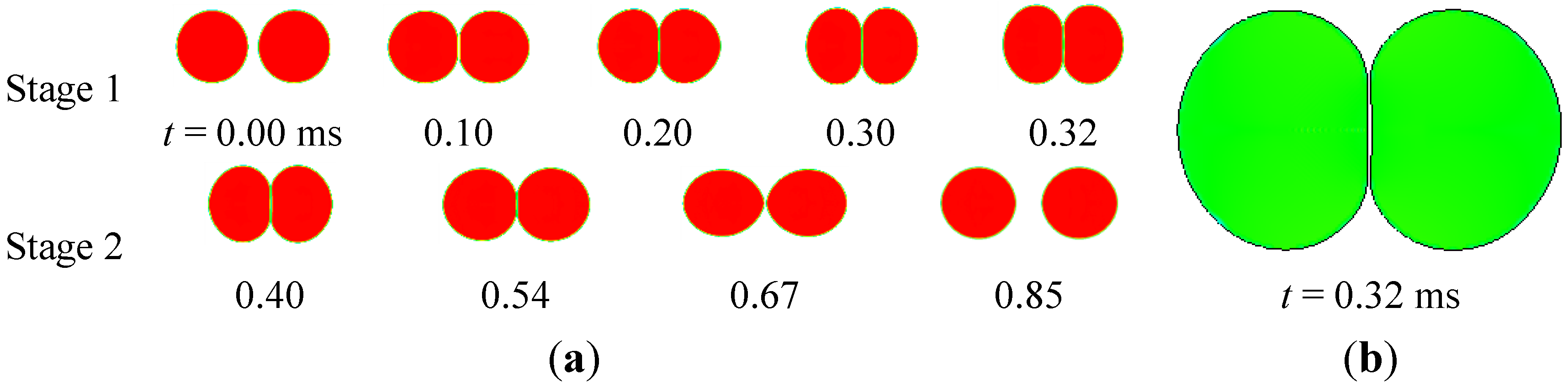
4.1. Bouncing Collision

As studied earlier [16], bouncing can occur if the gaseous film cannot be “squeezed out” when the droplets approach each other. Figure 6a (calculation conditions: D0 = 262 μm, We = 1.5, Re = 1.7) shows a sequence of photographs from the present simulations. From this figure, the collision process can be divided into two stages (the fluid radial expansion, recovery of the spherical shape and separation). As the droplets approach each other, pressure is built up in the gap (Figure 6a, t = 0.1 ms), subsequently, causing flattening of the droplets (Figure 6a, t = 0.2 ms, 0.30 ms), at t = 0.32 ms, the droplets reach their maximum deformation (Figure 6b). Subsequently, the droplets start to bounce, and recover of the spherical shape and separation. According to Qian and Law [11], the gap between the droplets is estimated to be of the order of ( ρ g R 0 3 u 0 2 / σ ) 0.5 , which gives a value of 5.3 μm, in good agreement with the value of 4.2 μm predicted by the present simulations.
Figure 6. (a) Time evolution for bouncing collision and (b) Gaseous film between the two colliding droplets.
Energies 06 00204 g006
As the two droplets approach each other, the gas between them is squeezed out, and thus two vortex ring are formed, as shown in Figure 7, t = 0.01 ms. Before the droplets collision, the fluid within droplets has its initial velocity and no velocity gradient, leading to high efficient viscosity (Figure 7, t = 0.01 ms). When the two droplets start to touch each other, the liquid surfaces deform and flatten due to gaseous film created; the flow within droplets is redirected into the direction parallel to the plane x = 0, leading to dynamic viscosity decreasing. At the same time, the strength of the vortices decreases gradually (Figure 7, t = 0.16 ms). Subsequently, droplets deformation attains a maximum value, and the strength of the vortices attains a minimum value (Figure 7, t = 0.32 ms), the fluid within droplets is at the stagnant state, leading to dynamic viscosity increasing.
Then, the droplets start to bounce and the gap widens, leading to dynamic viscosity decreasing. Simultaneously, the vortices change rotational direction, as ambient gas accelerates to fill in the gap between the two separating droplets (Figure 7, t > 0.32 ms).
In order to investigate difference between gel propellant (non-Newtonian fluids) droplet collision and base fluid (Newtonian fluids) droplet collision, base fluid (water) droplet collision was studied with the same conditions, and the outcome is coalescence. We can conclude that the fluid viscosity influences the outcome of droplet collisions. The reason is that high dynamic viscosity exists within droplets at the time of their maximum deformation (Figure 7, t = 0.32 ms).
Figure 7. Dynamic viscosity (Pa·s) and velocity field evolution for bouncing collision.
Energies 06 00204 g007

4.2. Coalescence Collision

According to the binary collision theory of Newtonian fluids, increasing Weber number leads to droplet coalescence. Based on the theory, we conducted numerical simulations on collision of two gel propellant droplets, increasing Weber number. Figure 8 (calculation conditions: D0 = 262 μm, We = 12.0, Re = 8.6) illustrates a sequence of images from these simulations. When the two droplets start to touch each other, a gaseous film is formed, leading to liquid surfaces deformation and flattening (Figure 8, t = 0.1 ms). Coalescence occurs at the rim of droplets in the gap area firstly, subsequently, the gas sheet is divided to several segments and entrapped into the droplet, becoming bubbles. At the same time, the merging droplet continues to expand in the radial direction, and becomes ellipsoidal (Figure 8, t = 0.3 ms). Next, the ellipsoidal droplet recovers the spherical shape and continues to extend along the axial direction, due to surface tension (Figure 8, t = 0.6 ms). After several radial expansions and axial extensions, a spherical droplet is formed.
Figure 8. Time evolution for coalescence collision.
Energies 06 00204 g008
A sheet of gas jet between the two approaching droplets is formed, which is the same as droplets bouncing, and on either side of the jet a vortex ring is also formed. The flow is redirected and accelerated in the region near the interface, which leads to decreasing viscosity (Figure 9, t = 0.03 ms). At t = 0.16 ms, two droplets attain coalescence, and the merging droplet continues expanding rapidly in the radial direction. At this moment, the high shear rate leads to a low viscosity. As the merging droplet reaches its maximum deformation (t = 0.28 ms), the fluid within the droplet is at the stagnant state, leading to a high dynamic viscosity. The flow within the droplet changes radial velocity direction; at the same time, the vortices also change rotation direction (Figure 9, t = 0.36 ms). Subsequently, the merging droplet continues to extend in the axial direction. Due to viscous dissipation, the velocity within the droplet decreases gradually, and thus the shear rate decreases, leading to increasing dynamic viscosity (Figure 9, t = 0.46 ms).
Figure 9. Dynamic viscosity (Pa·s) and velocity field evolution for coalescence collision.
Energies 06 00204 g009

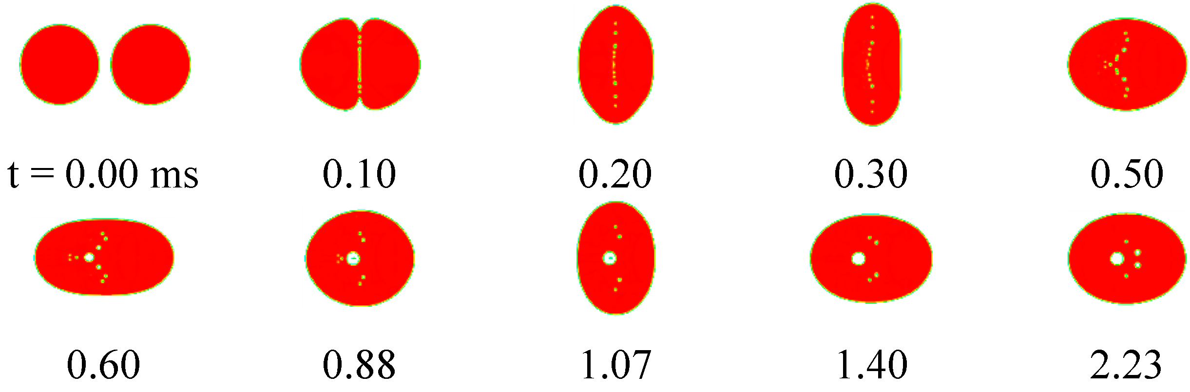
4.3. Reflexive Separation Collision

Increasing Weber number leads to droplet reflexive separation. The difference between droplet reflexive separation and coalescence is that the two droplets coalesce almost immediately after their initial contact; subsequently coalescence of the two initial droplets is followed by reflexive separation, and several satellite droplets are formed. Figure 10 (calculation conditions: D0 = 302 μm, We = 82.3, Re = 37.6) shows three stages during process of droplet reflexive separation. At the radial expansion stage of the merging droplet, the two droplets coalesce almost immediately after contact, and continue to expand in the radial direction, in such a way as to form a boundary ring with a thin connecting liquid disc inside (Figure 10, t = 0.25 ms). As the merging droplet reaches its maximum deformation, the first stage is over. At the stage of recovery of the spherical shape, the liquid continues to accumulate in the boundary ring; the center of the thin disc becomes continually thinner, but the radial velocity of the rim reverses its direction towards the center of the disc. The ring shape gradually transforms into a bell shape, extending in the axial direction. At the same time, gas is entrapped in the merging droplet and forms bubbles (Figure 10, t = 0.5 ms and 0.55 ms). At the stage of axial extension and separation, the droplet continues to extend in the axial direction, together with bubble motion, and gradually transforms into a cylinder. As the liquid mass continues to accumulate in the boundary droplets, a ligament is formed between the droplets (Figure 10, t = 1.37 ms), and its length is increasing with time. The tip droplets grow in size and the ligament becomes thin (Figure 10, t = 1.41 ms), when it is cut off from the boundary droplets. Subsequently surface tension effects transform the ligament to a satellite droplet (Figure 10, t = 1.53 ms).
Figure 11 displays the temporal evolution of the shear rate, velocity, and dynamic viscosity. At t = 0.1 ms, colliding is in the stage of radial expansion, an anticlockwise vortice appears in the gas field. The flow is redirected into the direction parallel to x = 0 plane (Figure 11b, t = 0.1 ms), leads to a maximum shear rate in the A region. At t = 0.32 ms, colliding is in the stage of recovery of the spherical shape. The rim moves towards the center of disc, which drives gas flow to rotate clockwisely. The flow is redirected between the rim and disc (B region), leading to shear rate increasing and viscosity decreasing. At t = 0.59 ms and t = 1.37 ms, colliding is in the stage of axial extension and separation. The flow extends in axial direction immediately, which drives gas flow to rotate clockwisely (Figure 10b, t = 0.59 ms). The minimum shear rate appears in the C region. At t = 1.37 ms, the flow is redirected between the ligament and tip droplet (D region), leading to high shear rate and low efficient viscosity.
Figure 10. Time evolution for reflexive separation collision.
Energies 06 00204 g010
Figure 11. (a) Shear rate (s−1), (b) velocity (m·s−1) and (c) dynamic viscosity (Pa·s) field evolution for reflexive separation collision.
Energies 06 00204 g011

4.4. Evolution of the Energy Budget

The total energy of the droplet collision system consists of the surface energy (SE), kinetic energy (KE), and cumulative viscous dissipation (DE). The SE and KE at an instant are nondimensionalized by initial SE and KE value, respectively. Figure 12a indicates that temporal evolution of KE is more remarkable than SE for bouncing collision. During the droplets approaching, the kinetic energy decreases remarkably, whilst the surface energy increases slightly, at the time of maximum droplet deformation (Figure 12a, t = 0.32 ms), both attaining minimum and maximum values, respectively. Then the kinetic energy and surface energy take on opposite variation trends.
Figure 12. Temporal evolution of surface and kinetic energy for (a) bouncing collision, (b) coalescence collision, and (c-1,2) reflexive separation collision.
Energies 06 00204 g012
Figure 12b indicates the temporal evolution of KE and SE for coalescence collision, which is different from bouncing collision. After the two droplets contact, the contact surface between two droplets disappearing leads to surface energy decreasing, then variation trend of the kinetic energy is opposite to the surface energy, and the deformation amplitude attenuates gradually. Finally, the surface energy tends to be stabilized at 81% of initial value and the kinetic energy approaches zero value.
Figure 12c-1 indicates that temporal evolution of KE and SE for reflexive separation collision for low Weber number. At the initial stage, variation trend of the kinetic energy is similar to coalescence collision. Then the kinetic energy decreases whilst the surface energy increases rapidly, at t = 0.3 ms, the surface energy attains maximum value, while the kinetic energy approaches zero value, then the KE and SE take on opposite variation trends. At t = 0.55 s, the KE recovers 25% initial value and the SE approaches the initial value. Finally, the KE approaches zero and SE tends to a steady value. Furthermore, with higher Weber number, the variation of SE is more remarkable, while the variation of SE is slight. Higher Weber number leads to the ratio between the initial kinetic energy and surface energy increasing (the ratio can be found from correlation: We/48), the impact becomes stronger, the surface energy attains higher maximum value (Figure 12c-2 ), and the cumulative viscous dissipation (DE) also increases. Therefore, the kinetic energy approaches zero gradually, and SE tends to steady value.

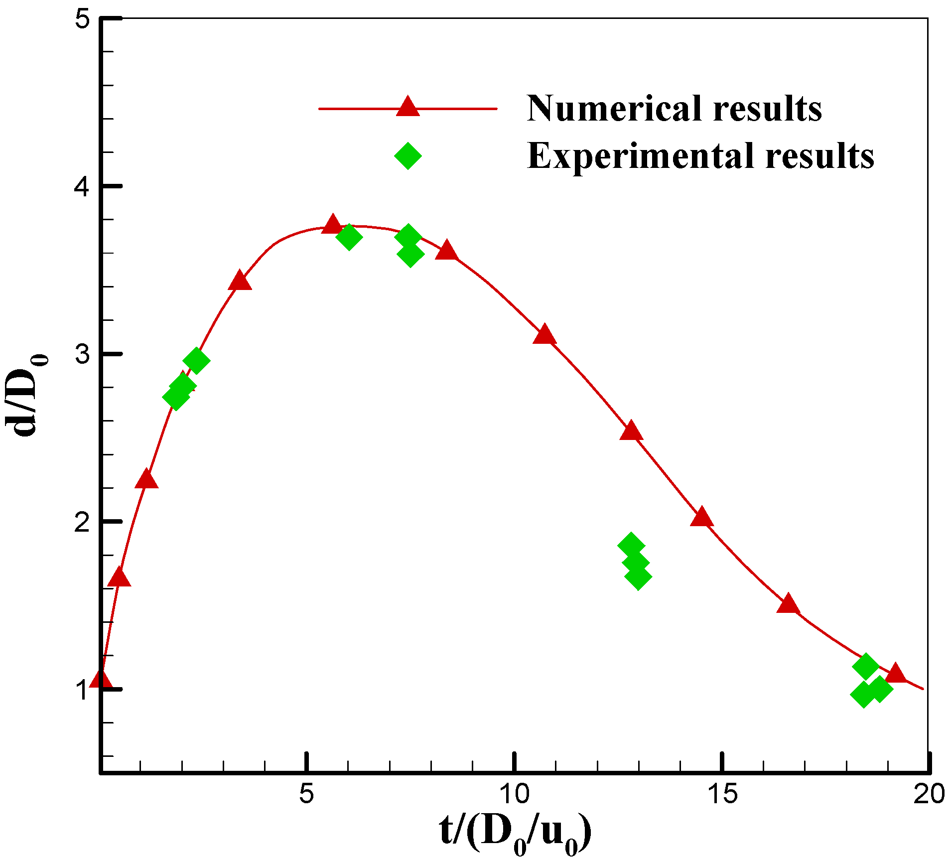
4.5. Maximum Deformation

The analysis on the energy budget indicates that the maximum deformation occurs in the stage of radial expansion, namely at the moment this stage is over. In order to investigate the evolution of deformations, two parameters in binary droplet collision, the dimensionless diameter, RH and the dimensionless center thickness δ , are defined as 2R/D0 and h/D0, respectively. D0 is the initial droplet diameter; R is the droplet radial height; h is the center thickness (Figure 13).
Figure 13. Schematic of fluid radial expansion.
Energies 06 00204 g013
Figure 14 shows the temporal variation of the dimensionless diameter RH and the dimensionless center thickness δ, and different droplet shape at the time of maximum RH and minimum δ for different Weber number. With increasing Weber number, the value of maximum RH also increases, while the moment of maximum RH shows a slightly increase (Figure 14a-1 ); the minimum δ decreases. When Weber number reaches 174.2, the minimum δ becomes zero value, namely a hole is created at the center of the thin disc.
Comparing Figure 144a-1 with Figure 14b-1, in the case of a low Weber number, the moment of maximum RH is not corresponding with minimum δ, the reasons being that when the radial velocity of the rim changes its direction towards the center of the disc, the flow within the thin disc continues to accumulate in the boundary ring, leading to the center of the thin disc continuing to become thin. However, in the case of a high Weber number, the impact is so strong that the dimensionless center thickness δ becomes zero value during the process of RH increasing, which leads to appearance of the minimum central thickness (δ = 0.0) earlier than its maximum deformation [Figure 14(a-2,b-2)].
Figure 14. Time evolution of the dimensionless diameter RH (a-1,2) and the dimensionless center thickness δ (b-1,2).
Energies 06 00204 g014

5. Conclusions

Binary collision of gel propellant droplets, which plays an important role in dense spray combustion process, was investigated numerically and theoretically. The VOF methodology was utilized to track the evolution of the gas-liquid free interface. Phenomena of rebound, coalescence and reflexive separation of droplets after collision are investigated, and the structure of the complicated flow fields during the collision process is also analyzed in detail. The main results can be summarized as follows:
(1)
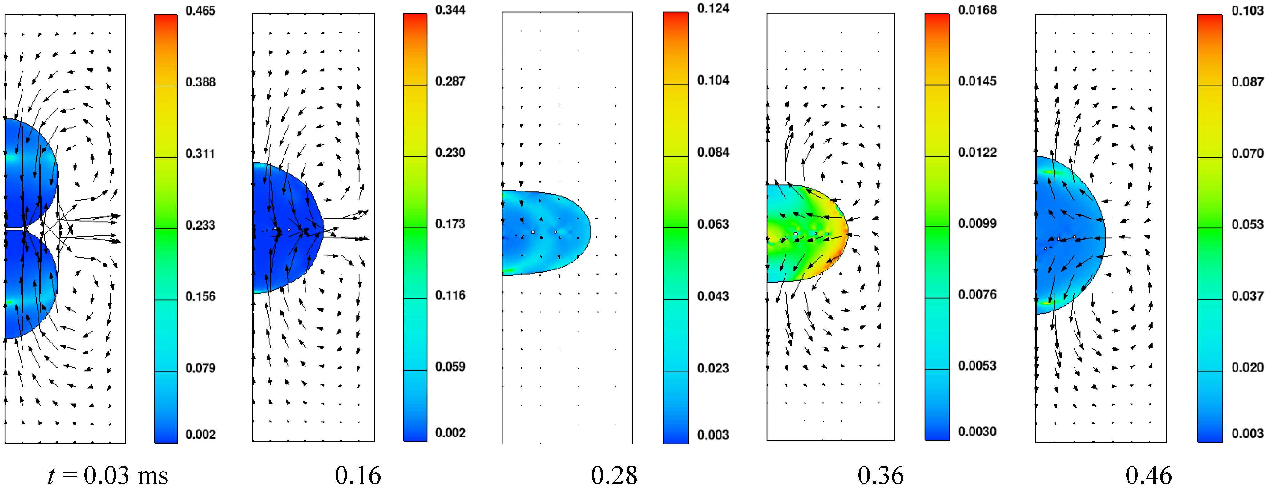
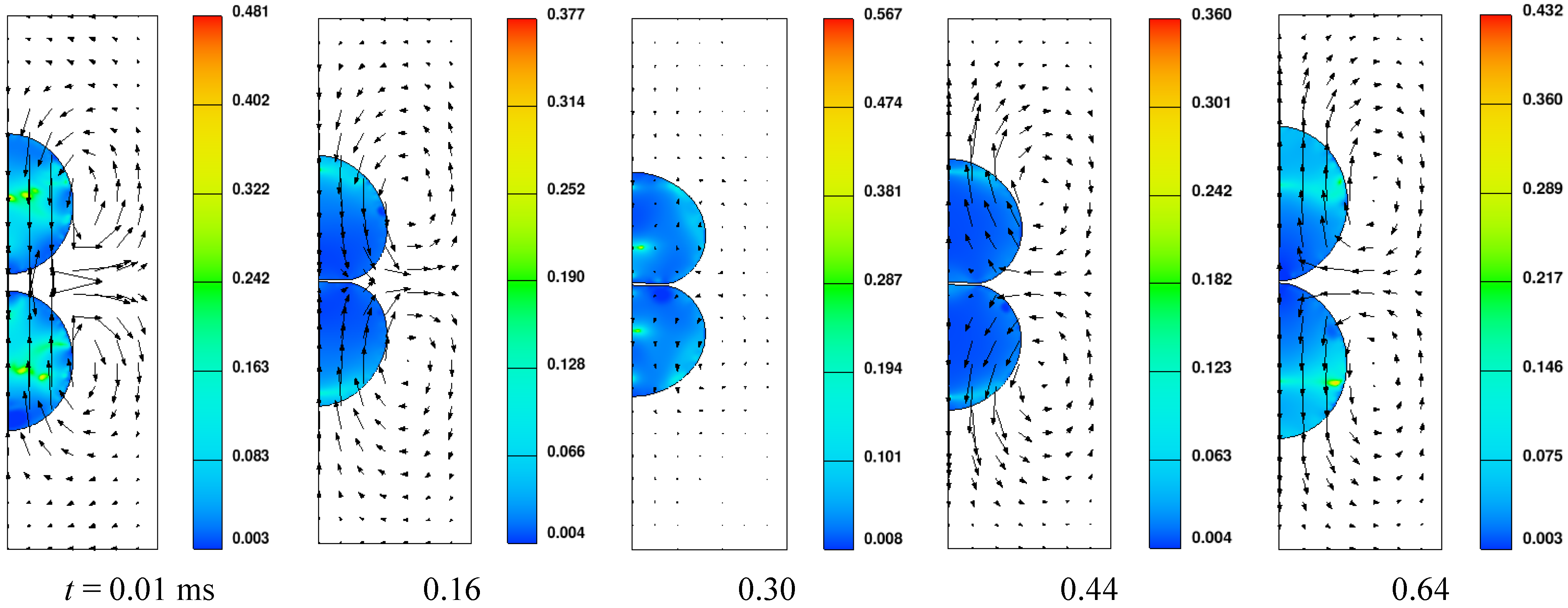
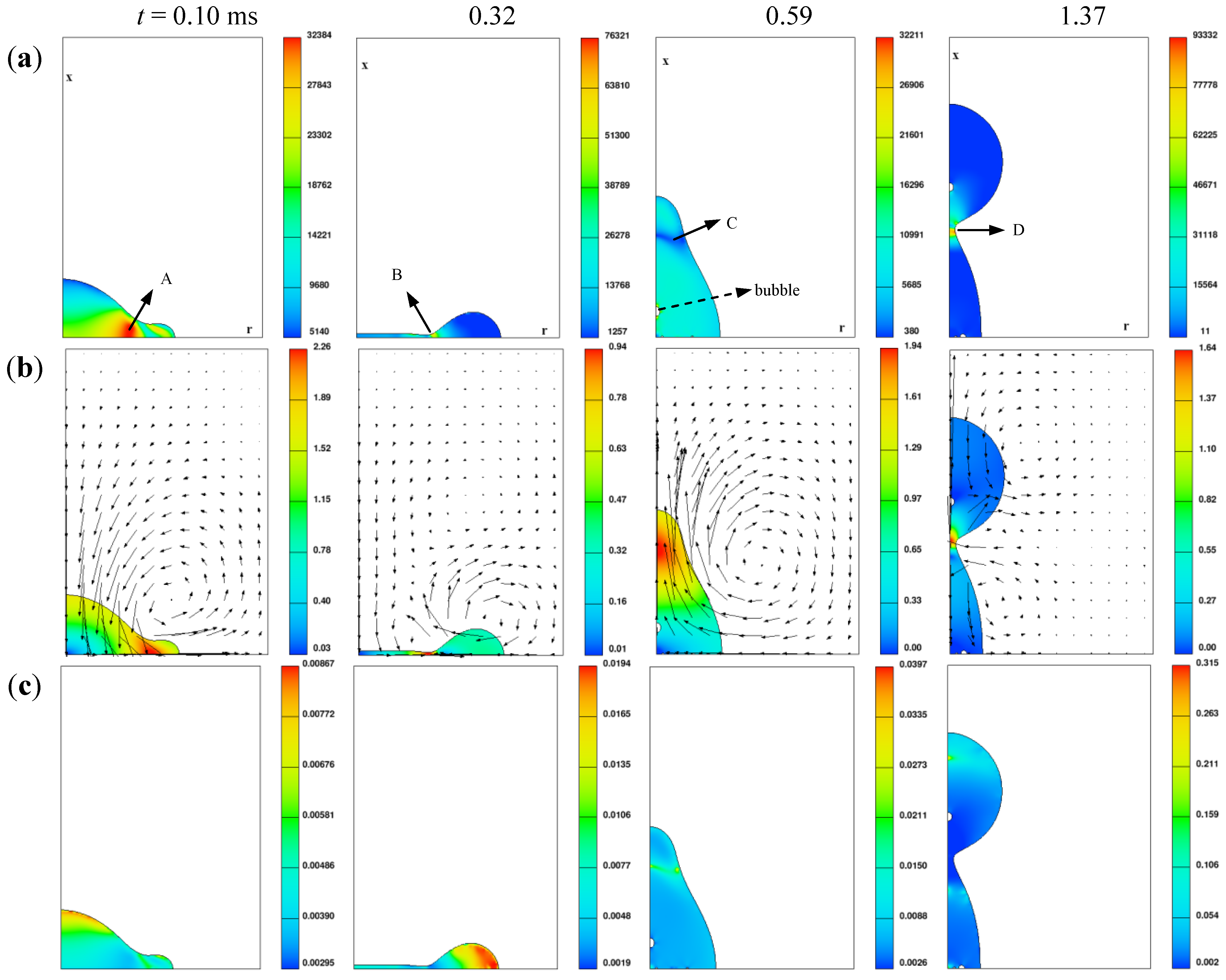
The VOF methodology is capable of predicting the details of complex flow configurations, like the evolution of the gas-liquid free interface, gas bubbles entrapment and coalescence, and ligament formation.
(2)
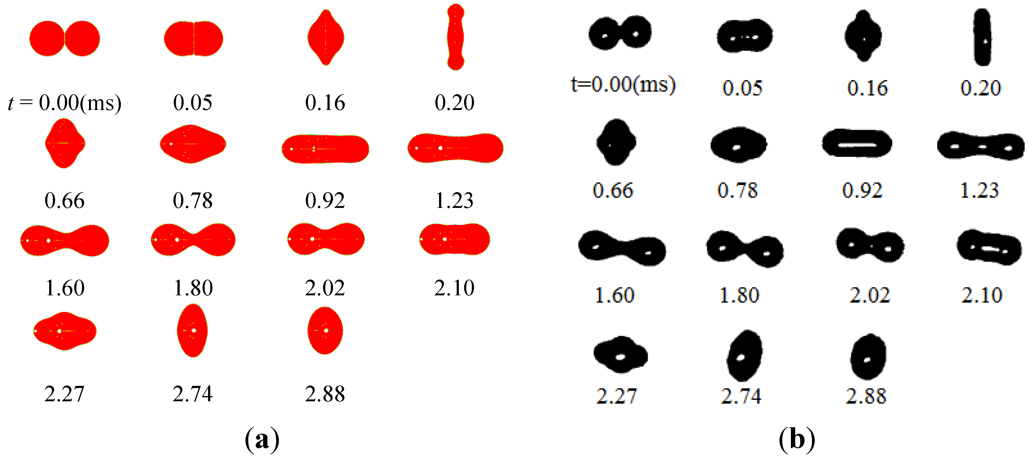
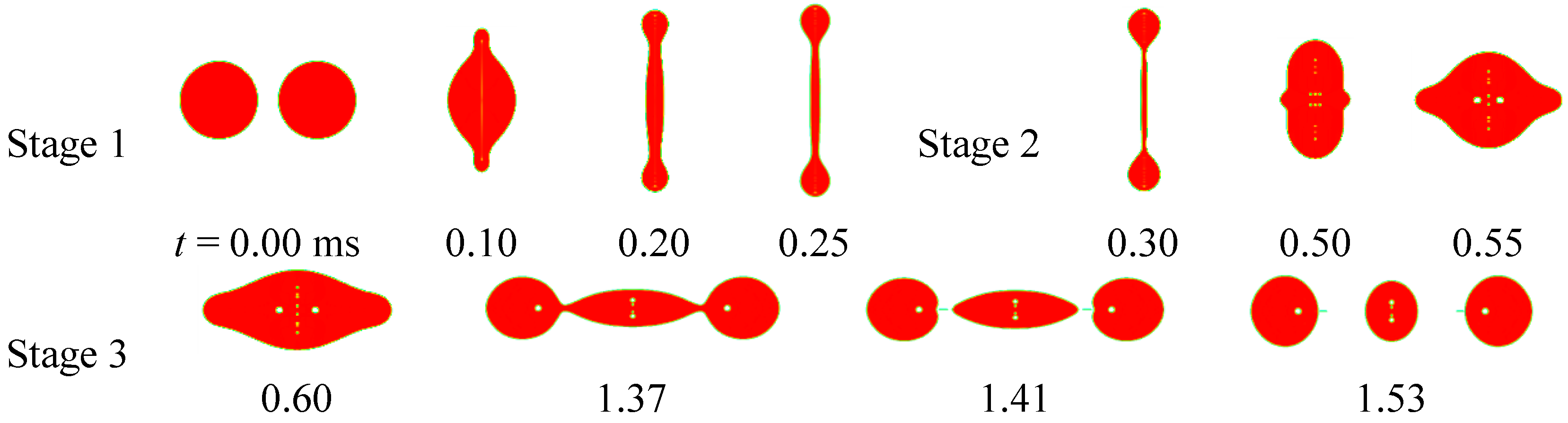
The maximum shear rate occurs at the point where the flow is redirected and accelerated, and minimum effective viscosity occurs at the corresponding point. Rebound of droplets is determined by the Weber number and viscosity of the fluid together. At the time of maximum droplet deformation, the fluid within droplets is at the stagnant state, and dynamic viscosity increases, leading to easier rebound in comparison with the base fluid droplets. The alternant appearance along with the deformation of droplets in the radial and axial direction is the main characteristic of the droplet coalescence process, and the deformation amplitude attenuates gradually. Three distinctive stages (radial expansion, recovery of the spherical shape, and the axial extension and reflexive separation) were identified for reflexive separation process of droplets.
(3)
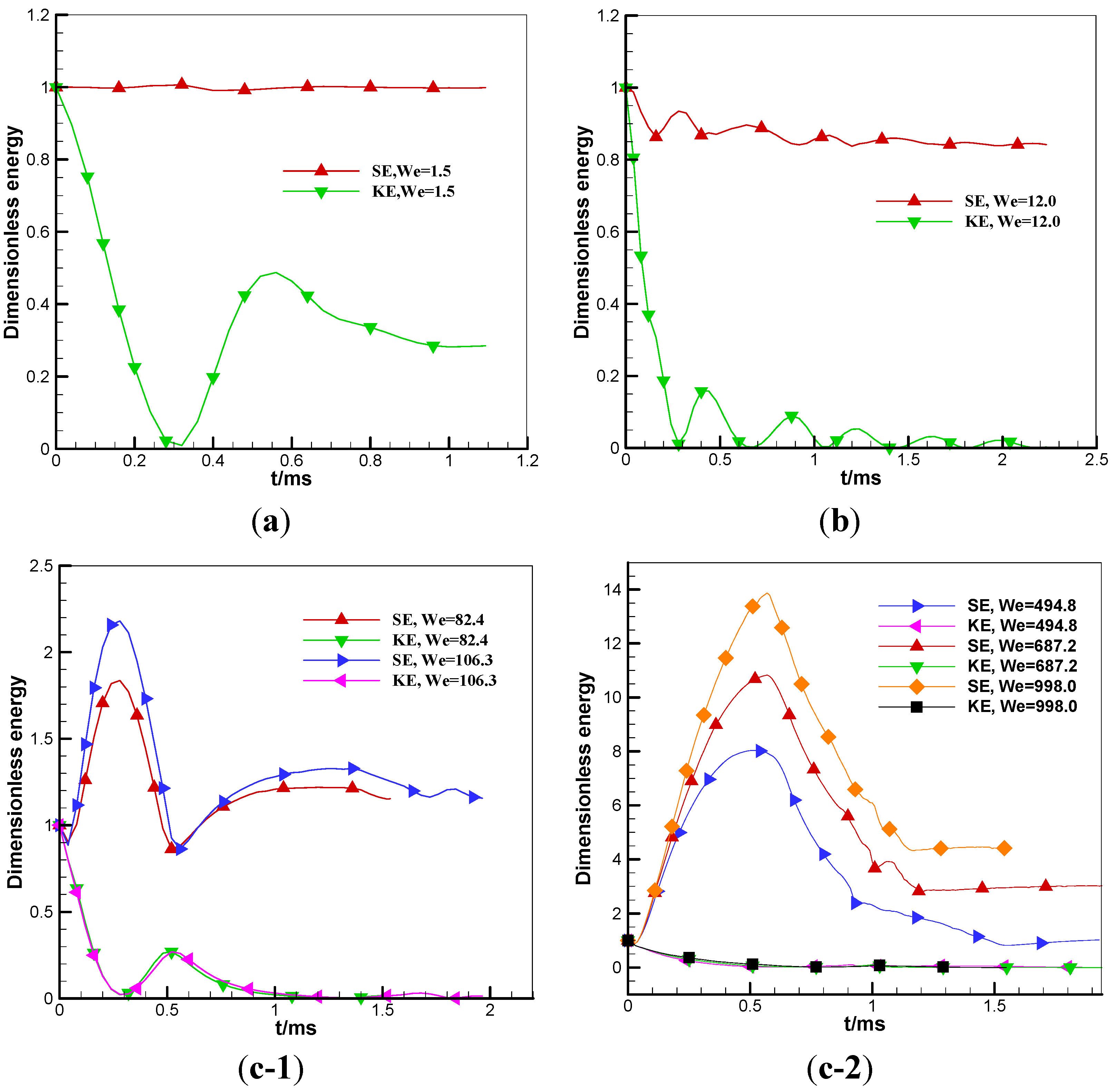
During the rebound process of droplets, the kinetic energy decreases remarkably, whilst the surface energy increases slightly. The kinetic energy and surface energy take on opposite variation trends for the process of droplet coalescence. The influence of Weber number on variation of surface energy is more remarkable, while the influence on variation of kinetic energy is small.
(4)
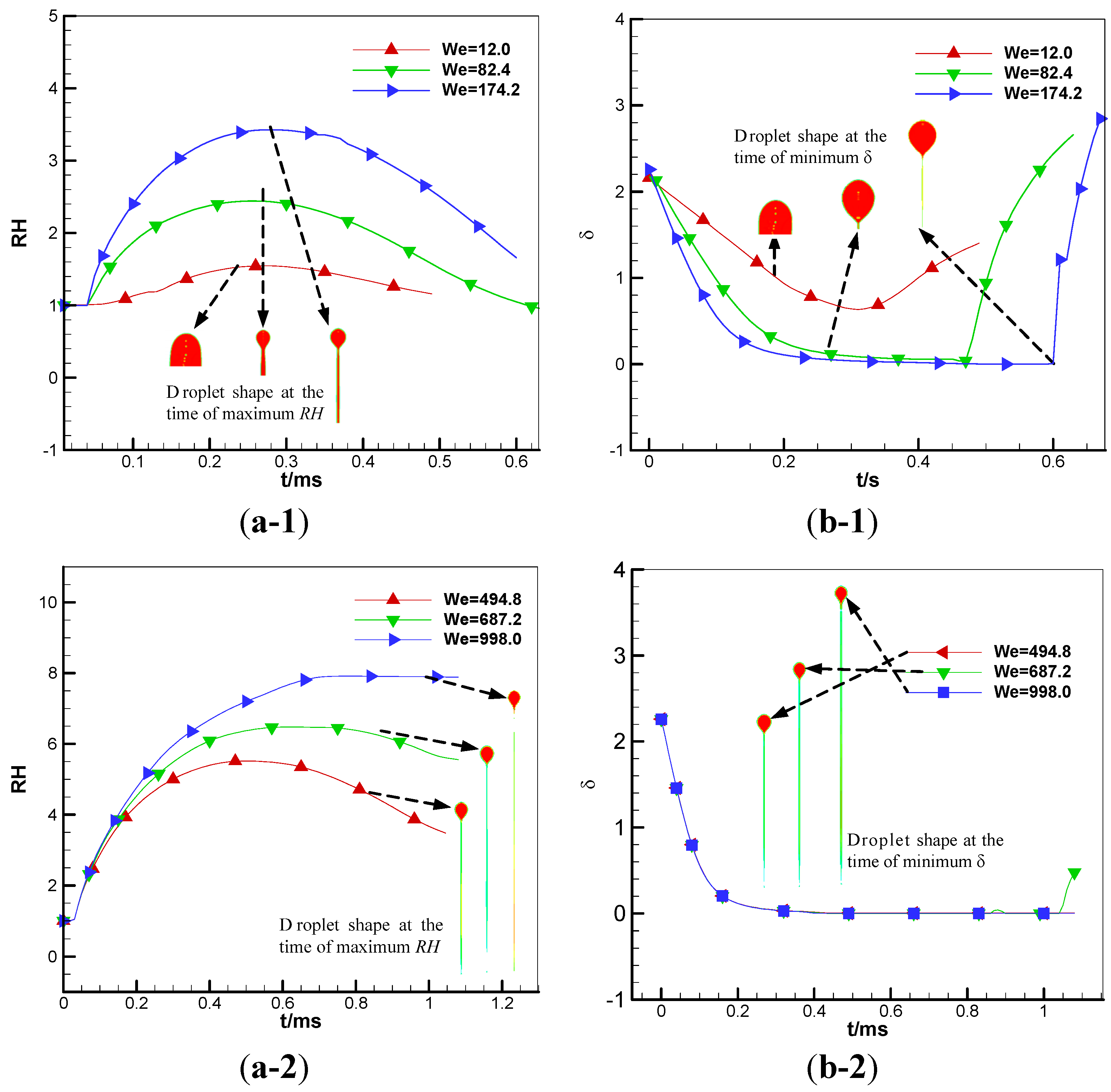
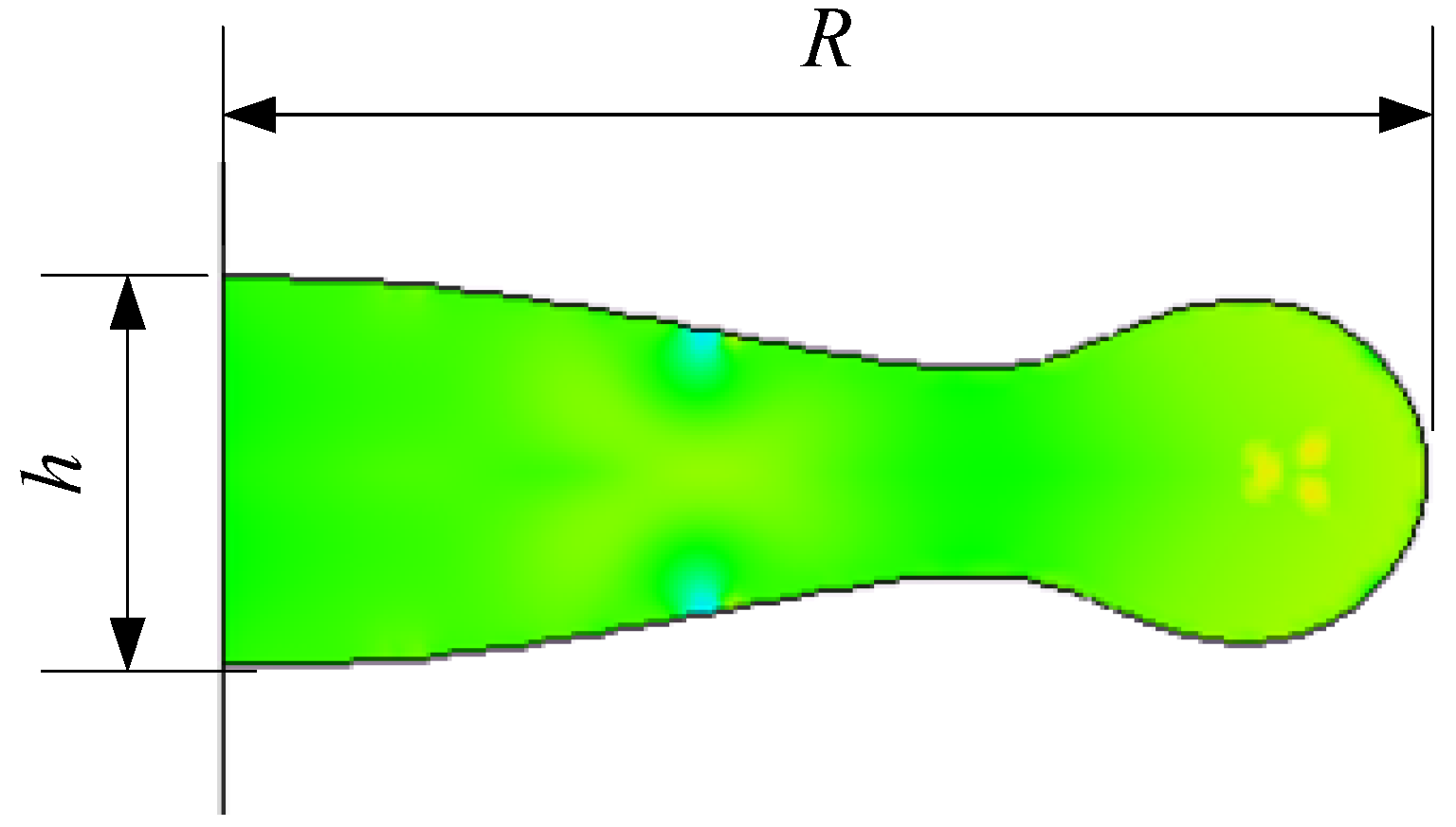
In the case of a low Weber number, the radial velocity of rim reverses its direction towards the center of the disc; the flow within the thin disc continues to accumulate in the boundary ring, which results in the minimum central thickness of a droplet appearance later than its maximum deformation. However, this result is contrary to the case of a high Weber number, because the dimensionless center thickness δ becomes zero during the process of RH increasing.

Acknowledgments

This work was supported partially by the National Science Foundation of China under Grant No.11172327. The authors also give great acknowledges and thanks to the College of Aerospace Science and Engineering at National University of Defense Technology for support of their work.

References

  1. Zhang, P.; Law, C.K. An analysis of head-on droplet collision with large deformation in gaseous medium. Phys. Fluids 2011, 23, 042102:1–042102:22. [Google Scholar]
  2. Natan, B.; Rahimi, S. The status of gel propellants in year 2000. Int. J. Energy Mater. Chem. Propuls. 2002, 5, 172–194. [Google Scholar]
  3. Liu, Z.J.; Wu, J.J.; He, Z. Investigation of Organic-gellant Droplets Evaporation Characteristics in the Static Environment. In Proceedings of 62nd International Astronautical Congress, Cape Town, South Africa, 3–7 October 2011; Volume 8, pp. 6336–6344.
  4. Solomon, Y.; Natan, B.; Cohen, Y. Combustion of gel fuels based on organic gellants. Combust. Flame 2009, 156, 261–268. [Google Scholar] [CrossRef]
  5. Liu, Z.J.; Hu, X.P.; He, Z.; Wu, J.J. Experimental study on the combustion and microexplosion of freely falling gelled unsymmetrical dimethylhydrazine (UDMH) fuel droplets. Energies 2012, 5, 3126–3136. [Google Scholar] [CrossRef]
  6. Klaus, M.; Helmut, K.C. Some Aspects of Rheological and Flow Characteristics of Gel Fuels with Regard to Propulsion Application. In Proceedings of 45th AIAA/ASME/SAE/ASEE Joint Propulsion Conference and Exhibit, Denver, CO, USA, 2–5 August 2009.
  7. Chen, X.D.; Ma, D.J.; Vigor, Y. Collision Outcome and Mass Transfer of Unequal-sized Droplet Collision. In Proceedings of 50th AIAA Aerospace Sciences Meeting Including the New Horizons Forum and Aerospace Exposition, Nashville, TN, USA, 9–12 January 2012.
  8. Chen, X.D.; Ma, D.J.; Khare, P.; Vigor, Y. Energy and Mass Transfer during Binary Droplet Collision. In Proceedings of 49th AIAA Aerospace Sciences Meeting Including the New Horizons Forum and Aerospace Exposition, Orlando, FL, USA, 4–7 January 2011.
  9. Ashgriz, N.; Poo, J.Y. Coalescence and separation in binary collision of liquid drops. J. Fluid Mech. 1990, 221, 183–204. [Google Scholar] [CrossRef]
  10. Brenn, G.; Frohn, A. Collision and coalescence of droplets of various liquids. J. Aerosol Sci. 1989, 20, 1027–1030. [Google Scholar] [CrossRef]
  11. Qian, J.; Law, C.K. Regimes of coalescence and separation in droplet collision. J. Fluid Mech. 1997, 331, 59–80. [Google Scholar] [CrossRef]
  12. Gotaas, C.; Havelka, P.; Jakobsen, H.A.; Svendsen, H.F. Effect of viscosity on droplet-droplet collision outcome: Experimental study and numerical comparison. Phys. Fluids 2007, 19, 102106:1–102106:17. [Google Scholar]
  13. Pan, K.; Law, C.K.; Zhou, B. Experimental and mechanistic description of merging and bouncing in head-on binary droplet collision. J. Appl. Phys. 2008, 103, 064901:1–064901:11. [Google Scholar]
  14. Focke, C.; Bothe, D. Computational analysis of binary collisions of shear-thinning droplets. J. Non-Newton. Fluid Mech. 2011, 166, 799–810. [Google Scholar] [CrossRef]
  15. Dupuy, P.M.; Lin, Y.; Fernandino, M.; Jakobsen, M.H.; Svendsen, H.M. Modeling of high pressure binary droplet collisions. Comput. Math. Appl. 2011, 61, 3564–3576. [Google Scholar] [CrossRef]
  16. Nikolopoulos, N.; Nikas, K.-S.; Bergeles, G. A numerical investigation of central binary collision of droplets. Comput. Fluids 2009, 38, 1191–1202. [Google Scholar] [CrossRef]
  17. Melissa, O. Experiments on droplet collisions, bounce, coalescence and disruption. Prog. Energy Combust. Sci. 1997, 23, 65–79. [Google Scholar] [CrossRef]
  18. Nikolopoulos, N.; Theodorakakos, A.; Bergeles, G. Off-centre binary collision of droplets: A numerical investigation. Int. J. Heat Mass Transf. 2009, 52, 4160–4174. [Google Scholar] [CrossRef]
  19. Nikolopoulos, N.; Strotos, G.; Nikas, K.-S.; Bergeles, G. The effect of Weber number on the central binary collision outcome between unequal-sized droplets. Int. J. Heat Mass Transf. 2012, 55, 2137–2150. [Google Scholar] [CrossRef]
  20. Dai, M.; Schmidt, D.P. Numerical simulation of head-on droplet collision: Effect of viscosity on maximum deformation. Phys. Fluids 2005, 17, 041701:1–041701:4. [Google Scholar] [CrossRef]
  21. Hirt, C.W.; Nichols, D.B. Volume of fluid (VOF) method for the dynamics of free boundaries. J. Comput. Phys. 1981, 39, 201–225. [Google Scholar] [CrossRef]
  22. Rahimi, S.; Peretz, A.; Natan, B. On shear rheology of gel propellants. Propellants Explos. Pyrotech. 2007, 32, 165–174. [Google Scholar] [CrossRef]

