1. Introduction
The employment of natural ventilation is almost as old as vernacular architecture. Examples include the wind assisted badgir or wind tower commonly used in the Middle East since 900 AD and the stack assisted chimneys developed since the Roman period. In the industrialized 19th and 20th centuries, solar stack ventilation was developed further with the introduction of the Trombe-Michel wall, modified Trombe wall and solar roof collector.
The principle of the solar chimney effect is a combination of solar stack-assisted and wind-driven ventilation. Air in the chimney expands due to solar heating and being relatively lighter, rises out of the chimney outlets, drawing the cooler air into the interior through the fenestrations. This pull effect is further complemented by the push effect from the ambient wind. The stack pressure difference driving the air movement is a combination of the different densities between the interior and ambient environment as well as the stack height where the greater the stack height and temperature difference, the stronger the pressure difference. In solar assisted stack ventilation, the temperature difference is achieved from heat gained due to solar irradiance.
Research has determined the operability of implementing solar chimneys in the hot, cloudy and humid tropics. This paper aims to discuss the performance of tropical solar chimneys by varying the design parameters and examining their effects on the interior air temperature and speed.
2. Literature Review
In general, there are various different configurations of solar chimney going by many names like thermal chimney and roof solar collector. However, to be considered a solar chimney, the basic principle is to employ the sun to produce an updraft of air along a channel. With increasing interests in solar chimney research, various theoretical, experimental and computational researches across different weather conditions were examined [
1,
2].
The solar chimney concept originated with the developments of mathematical models for the Trombe wall and the solar roof collector. Ohanessian and Charters [
3] examined the effects of glazing and wall thickness on the modified Trombe-Michel wall during the winter in Melbourne, Australia using finite difference simulation. Around the same period, Akbarzadeh
et al. [
4] conducted experiments with a modified Trombe wall at a building roof in the University of Melbourne, Australia. Similarly, Das and Kumar [
5] experimented with a flat-plate solar chimney employed to dry agricultural products.
Awbi [
6] gave an introduction of the various methods of natural ventilation and examined the effects of wind and solar-induced ventilation theoretically using vertical and inclined solar chimneys. Results showed that the influence of wind was greater than the stack effect while the inclined solar chimney performed better due to its greater exposed surface area. Aboulnaga [
7] carried out theoretical analysis on a common resident building in Al-Ain city, UAE. The solar chimney’s depth and inclination angles were varied. Results gave an optimum inclination angle of 35° and a solar chimney depth of 0.20 m.
Khedari
et al. [
8] examined the effects of the modified Trombe wall in a room. Results showed that a bigger air gap or a darker colour on the wall induced more airflow. Hirunlabh
et al. [
9] studied a south-facing metallic solar wall (MSW) incorporated in a house. Six experimental points were placed within the house at 1.00 m above the ground. Results showed that temperature within the MSW increased with wall height and decreased with the air gap’s depth. In addition, mass flowrate increased with increasing stack height and solar chimney’s depth.
Afonso and Oliveira [
10] compared the differences in air change rate and volume flowrate between conventional and solar chimneys under weather conditions in Lisbon, Portugal. Measurement showed that a higher and wider chimney improved volume flowrate although the width is more significant. Khedari
et al. [
11] conducted experiments on a school building installed with two roof solar chimneys, a modified Trombe wall, a Trombe wall and a metallic solar wall to determine their combined effects. 27 different positions were used to obtain the interior air temperatures and speeds.
Spencer
et al. [
12] performed scaled experiments with a solar chimney model using a 4 wt % aqueous saline solution and hydrogen bubbles to simulate the thermal stack due to solar irradiance. Results showed that the solar chimney’s optimal width is independent from solar irradiance but increased with stack height and the opening area. Furthermore, increasing the opening area of the interior’s inlet and solar chimney’s inlet increased the volume flow rate although the influence of the solar chimney’ inlet area is more significant.
Hirunlabh
et al. [
13] examined different configurations of the roof solar collector using experiments and finite difference simulations. Results showed that the airflow rate increased with the inclination. In addition, although increasing the height of the roof solar collector increased the airflow rate, it led to a decrease in the airflow rate per unit area.
Letan
et al. [
14] performed verification between scaled and simulated five-story buildings and found that simulated turbulent flow and the experimental results were in good agreement. This was followed by a full scale three-dimensional k-ε turbulence simulation with specified outdoor and wall temperatures. Results showed that the airflow rate was much lower at the higher stories and can be improved with the addition of an attic. Furthermore, a higher airflow rate lowered the room temperature closer to the ambient.
Drori and Ziskind [
15] carried out experiments on a real-size one-story building and compared the results with simulations using FLUENT software (ANSYS, Canonsburg, PA, USA). The building was located in the Negev Desert, Israel. With the solar ventilated ducts, the indoor air temperature remained similar to the ambient temperature throughout the afternoon. Using the standard k-ε turbulence model, simulations showed that the airflow distribution was similar along the width of the building.
Gratia and De Herde [
16] simulated the airflow rate through a double skin façade of a middle size building located in Uccle, Belgium during the summer day of 24 July. Several orientations of the double skin façade and the wind directions were analyzed. TAS (EDSL, Milton Keynes, UK) simulation results showed that a south-facing double skin façade under the east or west wind directions performed the best. Ballestini
et al. [
17] modelled an actual old factory in Italy using LOOPDA (NIST, Gaithersburg, MD, USA), a two-dimensional natural ventilation software, and TRNSYS (TRNSYS, Madison, WI, USA), a thermal balancing software, to determine the temperature and ventilation with the addition of a double-skin façade.
Amer [
18] examined the various passive cooling techniques on a scaled cubic building. The south-facing solar chimney led to a drop in the room temperature when compared to the base case and gave a temperature which on average, was 1.0 °C higher than the ambient temperature.
Gan [
19] carried out a two-dimensional simulation of solar chimney using software FLUENT with standard k-ε turbulence modeling after model validation with experimental data. The optimal depth for volume flowrate remained unchanged with solar irradiance. Furthermore, reverse flow was observed when the optimal depth was exceed. Lastly, the air speed within the solar chimney decreased with increasing depth.
Miyazaki
et al. [
20] carried out simulations and analytical analysis of the effects of solar chimney on an office room under Tokyo (Japan) weather conditions. A temperature dependent density together with the RNG k-ε turbulence model was employed using FLUENT software while constant pressure and zero initial velocities were applied at the inlet and outlet with the solar chimney attached to the south-facing wall. After model validation, simulated results showed that the effect of solar chimney’s depth was insignificant after 0.2 m. Furthermore, higher solar irradiance or lower ambient temperature will result in a higher volume flowrate.
Bacharoudis
et al. [
21] predicted the air velocity and temperature within a solar chimney using two-dimensional, incompressible and steady state FLUENT simulations with Boussinesq approximation. Various different turbulence models were examined and the realizable k-ε model was found to be the most suitable. Furthermore, simulated results predicted that increasing the outer wall temperature caused an increase in the volume flowrate and air temperature.
Tan and Wong [
22] examined the solar chimney’s performance in the tropics serving the interior within a building. Results showed that the interior air temperature cooled down faster and heated up slower. In addition, the solar chimney’s inlet position was found to influence the interior air speed.
From the literature review, it is clear that research on the application of solar chimneys is generating interests worldwide. However, the state-of-the-art research generally concentrates on temperate countries with weather conditions very different from the tropics. The tropics is different from the temperate regions in term of the sun’s solar path, the amount of solar irradiance and cloud cover, rendering solar chimney research in the tropics significantly different.
3. Methodology
From the published literature, many different parameters affect the performance of the solar chimney. Solar irradiance is the most widely research parameter and also the most conclusive. Researchers find that air speed and temperature within the solar chimney increase with increasing solar irradiance. Within the interior, there is also a temperature drop and temperature lag. However, the value of solar irradiance is fairly constant during the hot tropical afternoon and the interior will already be thermally comfortable during low solar irradiance. Hence, solar irradiance is fixed at 900 W/m2, the average value during the hot tropical afternoon.
The second parameter is the ambient air speed. Researchers give mixed and limited review on this parameter. However in the tropics, solar irradiance is dominance as compared to the ambient air speed due to the relatively high solar irradiance and low ambient air speed. Therefore, tropical solar chimney is recommended to be employed under zero ambient air speed.
The inclination angle of the solar chimney is another widely research upon parameter, from fully horizontal to fully vertical. The greater the inclination angle, the higher the stack height, the lesser the flow resistance and the better the performance; however, the smaller the angle, the greater the exposure to solar irradiance and also the better the performance. Solar chimney is usually integrated into roof design where designers decide the roof’s inclination angle based on building codes. Hence, the roof’s and solar chimney’s inclination angle is fixed at 45° to the horizon; the maximum inclination angle under tropical Singapore’s building codes.
Although solar chimney predominately employed glass glazing as its exterior surfaces, there are increasing examples using roof tiles or metal sheets as alternative. Generally, glass glazing amplified the greenhouse effects which increase the thermal stack within the solar chimney but allow heat to be transferred into the interior if insulation fails; non-glass glazing absorbed higher solar irradiance and less heat energy is transferred to the air within but as the exterior surface is of higher temperature than the interior surface, non-glass glazing actually acts as a thermal buffer for the interior. Mild steel solar chimney is employed in the tropics as the material and construction costs are lower with greater construction ease on new buildings or retrofitting on existing buildings. A dull and dark color coating with an absorptivity value of 0.80 is further proposed.
In the area of interior configuration, the volume of the interior space and the size of its fenestrations are possible input parameters that may affect the performance of the solar chimney. However, limited research are found; this may be because the interior volume and fenestrations size are normally fixed to cater for its function and the configuration of the solar chimney is instead designed based on these pre-determined values.
3.1. Physical Model and Parameterization
The interior space on the ground floor of a building with solar chimney is assumed a square area of 64.00 m2 with a height of 3.00 m, a typical interior size of classrooms in schools, living rooms in private residential estates or manufacturing workspace in flatted factories, where the solar chimney is incorporated into the roof. The fenestration will face north with an area of 9.00 m2 (1.50 m in height by 6.00 m in width giving a window-to-wall ratio of 37.5%) while the solar chimney will face south (placed in the middle of the façade) in order to maximize the amount of solar irradiance. The ambient air outside the interior’s fenestration is fixed at 31 °C as it is normally shaded with overhangs.
Generally and fairly conclusive, researchers have found that the higher the stack height, the greater the performance although the effect of stack height may need to be examined together with other aspect ratio like the depth and width of the solar chimney. The parameterization of the solar chimney’s stack height is bounded by the height of the building (including the height of the roof), ranging from two stories to four stories giving a stack height of 7.00 m to 21.00 m, the number of stories typical of flatted factories or schools in the tropics. The stack height increases with a height of 3.50 m, the height of a typical level. As the solar chimney is incorporated into the roof with a fixed inclination angle of 45° (tropical Singapore’s building codes), the length of its inclined portion will be the cosine of half of the interior’s length, giving a fixed value of 4 × cos 45° = 2.83 m.
The depth of the solar chimney generates significant amount of research due to the possibility of an optimal depth. The understanding principal shows that friction losses are significant and slow down the air speed at small depth. However at large depth, the thermal boundary layers may no longer cross each other, together with the possibility of backflow of air, leading to lower heat transfer. Currently, researchers return mixed reviews about the influence of the solar chimney’s depth. The solar chimney’s depth is bounded by 0.10 m and 0.90 m with an increment of 0.20 m; depths lower than 0.10 m give fairly low air speed according to published literature while depths higher than 0.90 m will be physically too large relative to the building.
The width of the solar chimney is a parameter commonly overlooked as most research found that airflow within the solar chimney is generally two-dimensional flow. However, several researchers note that the width will directly affect the volume flowrate and the interior air speed. Similarly, the width of the solar chimney is bounded from 1.00 m to 7.00 m (as the width of the interior is 8 m) with an increment of 2.00 m.
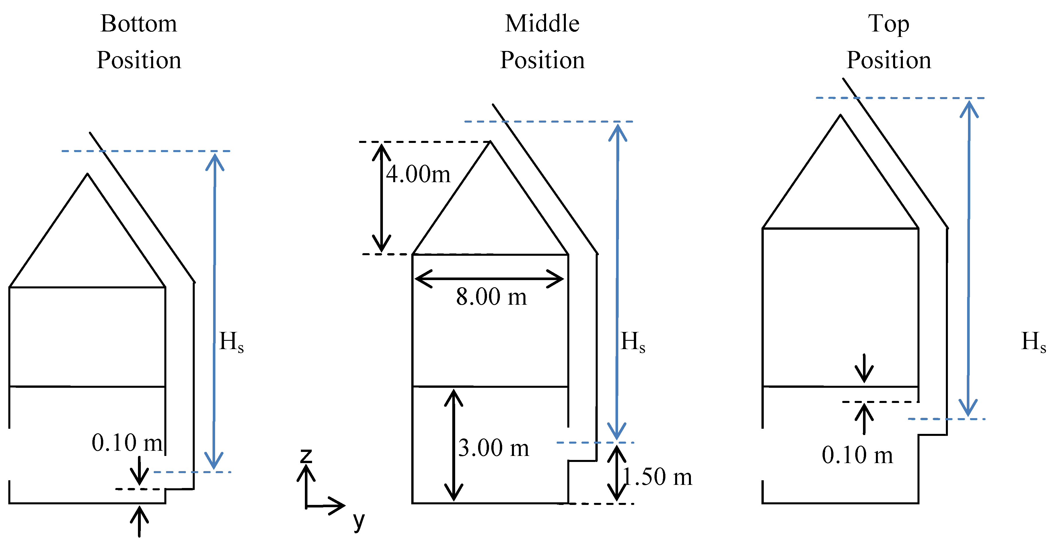
Researchers further examine the positions of the solar chimney’s inlet where positions range from the ground to the ceiling. This parameter generates limited literature; however, the results are interesting. Generally, the interior air temperature profile is not affected but the air speed profile is found to depend significantly [
23]. If the height of the building is fixed, the position of the solar chimney’s inlet will indirectly affect its stack height. To de-couple this relationship, the inlet position is varied independently from the stack height; when the inlet position is shifted upwards, the entire solar chimney duct is shifted upwards concurrently, assuming that the height of the building will increase to accommodate the stack height, as seen in
Figure 1 where there are three inlet positions located at the bottom, middle and top position with respect to the ground.
Figure 1.
Relationship between solar chimney’s stack height and inlet position (side view).
Figure 1.
Relationship between solar chimney’s stack height and inlet position (side view).
Furthermore, the height of the solar chimney’s inlet is equal to the solar chimney’s depth. Hence, from
Figure 1 referring to the bottom position, as the lower bound of inlet is fixed at 0.10 m above the ground, a solar chimney’s depth of 0.10 m and 0.90 m will cause the inlet’s mid-plane to be 0.15 m and 0.55 m above the ground respectively. Similarly, for the top position, the upper bound of the inlet is fixed at 2.90 m above the ground where a solar chimney’s depth of 0.10 m and 0.90 m will cause the inlet’s mid-plane to be 2.85 m and 2.45 m above the ground respectively. For the middle position, as the inlet’s mid-plane is fixed at 1.50 m above the ground, it remains constant for all solar chimneys’ depth.
Other than the four input parameters, the two output parameters are defined as the area-weighted average air temperature and air speed on the horizontal plane 1.20 m above the ground as defined in Singapore’s Green Mark Scheme [
24]. With the input parameters parameterized, their median values are taken as base case, as summarized in
Table 1 before further developing the physical model into the computational model.
Table 1.
Parameterization ranges of four input parameters.
Table 1.
Parameterization ranges of four input parameters.
| Input parameters | Parameterization range | Base case |
|---|
| Lower bound | Upper bound | Increment | No. of values |
|---|
| Solar Chimney | Stack Height | HS | 7.00 m | 21.00 m | 3.50 m | 5 | 14.00 m |
| Depth | DS | 0.10 m | 0.90 m | 0.20 m | 5 | 0.50 m |
| Width | WS | 1.00 m | 7.00 m | 2.00 m | 4 | 5.00 m |
| Inlet Position | PS | Bottom Position | Top Position | Middle Position | 3 | Middle Position |
3.2. Computational Model
FLUENT is selected as the computational software for simulating the physical model as it is widely used by researchers internationally [
14,
15,
19,
20,
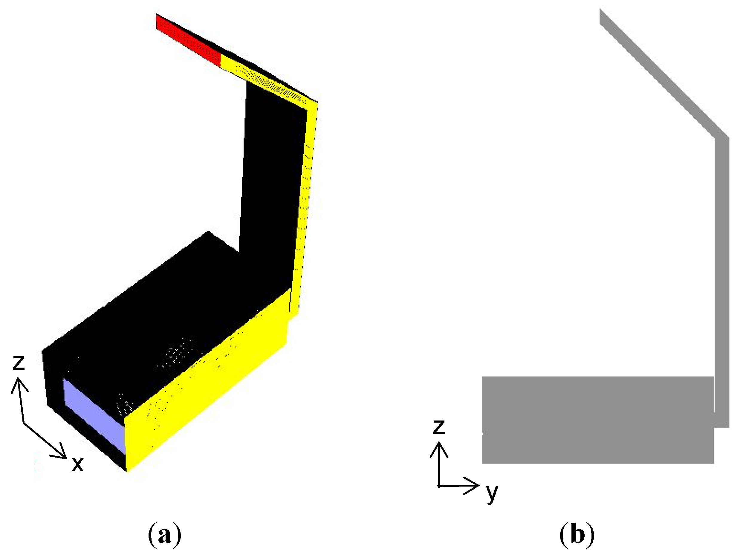
21] in the area of solar chimney research. The computational model is developed from the physical model by ignoring the stories and roof above the ground floor (
Figure 2). Furthermore, employing symmetry, only half of the domain is modelled. The computational model is validated with experimental data to be published in a fore coming paper, where the computational and experimental data of the air temperature and speed within the solar chimney as well as the interior are found to be comparable. Furthermore, these data pass the statistic paired
t-test where the null hypothesis, the means of the experimental and computational data are equal to each other, is accepted.
Figure 2.
(a) Computational model in isometric view; (b) Computational model in mid-plane view.
Figure 2.
(a) Computational model in isometric view; (b) Computational model in mid-plane view.
3.2.1. Boussinesq Approximation and Turbulence Modeling
The equations for the conservation of mass and momentum are modeled with no external sources and simulations are carried out under steady state as the ambient solar irradiance is found to be fairly constant during the hot tropical afternoon. In addition, the evaluation of the gradients and derivatives are carried out using the least square cell-based evaluation method since the flow solution is solved on polyhedral meshes.
The species diffusion and viscous dissipation in the energy equation are ignored as the Brinkman number is much less than unity. Furthermore, no radiation model is used as radiation heat transfer is small within the solar chimney duct as compared to conduction and convection. As the ratio of the Grashof and Reynolds numbers is near unity, strong buoyancy is expected. Furthermore, the Rayleigh number is of the order of 1012, indicating that the flow is turbulent.
The buoyancy of air is modeled using the Boussinesq approximation as the solar chimney stack effect is natural convection under small change in air temperature. The computational model considers density to be constant except for the buoyancy term in the momentum equation.
As the Rayleigh number indicates that the flow is turbulent, additional transport equations need to be specified to obtain “closure” for all the unknown quantities. The additional Reynolds stresses in the turbulent momentum equations are modeled using the Boussinesq hypothesis; the anisotropy of turbulence flow is insignificant in natural convective flow and hence Reynolds stress models are not selected. Among the various turbulent models that employ that Boussinesq hypothesis, the realizable k-ε model is used due to its better performance under strong pressure gradient.
Furthermore, the near-wall regions need to be modeled as these are the main sources of vorticity and turbulence. As solar chimney stack flow is buoyancy-driven flow, the near-wall model approach is employed over the wall function approach. FLUENT employs the enhanced wall treatment using the two-layer approach where in the fully turbulent region, the selected realizable k-ε model is in force while in the viscosity-affected near-wall regions, turbulent viscosity is computed from the one-equation model of Wolfstein. As the flow is natural convective, both the pressure gradient effects and thermal effects are selected.
The pressure-based segregated algorithm using the predictor-corrector approach is employed on the governing equations. Furthermore, the SIMPLE pressure-velocity coupling method is used as the computational model is under steady state condition with relatively simple geometry.
The discretizations of momentum, turbulent kinetic energy, turbulent dissipation rate and energy are subjected to the second order upwind scheme as accuracy is preferred over better convergence. In addition, PRESTO! is used as the pressure interpolation scheme as solar chimney flow is high Rayleigh number natural convection flow.
3.2.2. Boundary Conditions and Convergence Criteria
Pressure inlet and outlet boundary conditions are applied to the fenestration and solar chimney’s outlet respectively as the physical domain is subjected to zero ambient air speed and air movement is purely due to the solar stack effect. Hence, the total gauge pressure at the inlet is zero while the inlet temperature is 31 °C.
Other than the computational inlet and outlet, the rest of the surface boundaries are stationary walls under no-slip conditions. All interior wall surfaces are under zero heat flux while the solar chimney exterior surfaces are subjected to heat flux of 720 W/m2 (absorptivity value of 0.80 with a solar irradiance of 900 W/m2). The solar chimney surfaces are modelled by including the 3 mm thick mild steel plates into the computational model.
All residuals are scaled and convergence criteria is reached when the default absolute value of the residuals are below 10−6 for energy and 10−3 for the other quantities. However, it is important to note that a good initial guess may lead to a high scaled residual and hence convergence cannot be achieved. Hence, both the net mass flow and heat transfer rate reaching less than 0.1% are set as additional convergence criteria. Furthermore, the two output parameters, the output air temperature and air speed, should have stabilized.
4. Results and Discussion
With the computational model developed, the effects of the four input parameters: Stack Height (Hs), Depth (Ds), Width (Ws) and Inlet Position (Ps) are simulated to understand their influences on the two primary output parameters. The parameterization of these four input parameters gives rise to 300 possible different combinations, of which 139 cases (46%) are selected and simulated.
To determine whether the solved flow solution is independent of the mesh grid, grid adaption is carried out based on the gradients of the flow velocity. The curvature approach is used as the solar chimney flow gives smooth solution. In addition, the refine threshold is fixed such that approximate 25% of the grid is refined. It is found that the mass flowrate, heat transfer rate as well as air temperature and speed at the computational inlet, computational outlet and output plane are similar to two significant figures before and after grid adaption. This observation gives the confidence that the simulated solution is indeed independent of its grid.
4.1. Base Case Analysis
The base case with its corresponding solar chimney’s stack height, depth and width of 14.00 m, 0.50 m and 5.00 m respectively, together with its inlet at the middle position, is examined to understand the influences of solar stack on air temperature and speed distribution.
4.1.1. Air Temperature and Speed within Solar Chimney
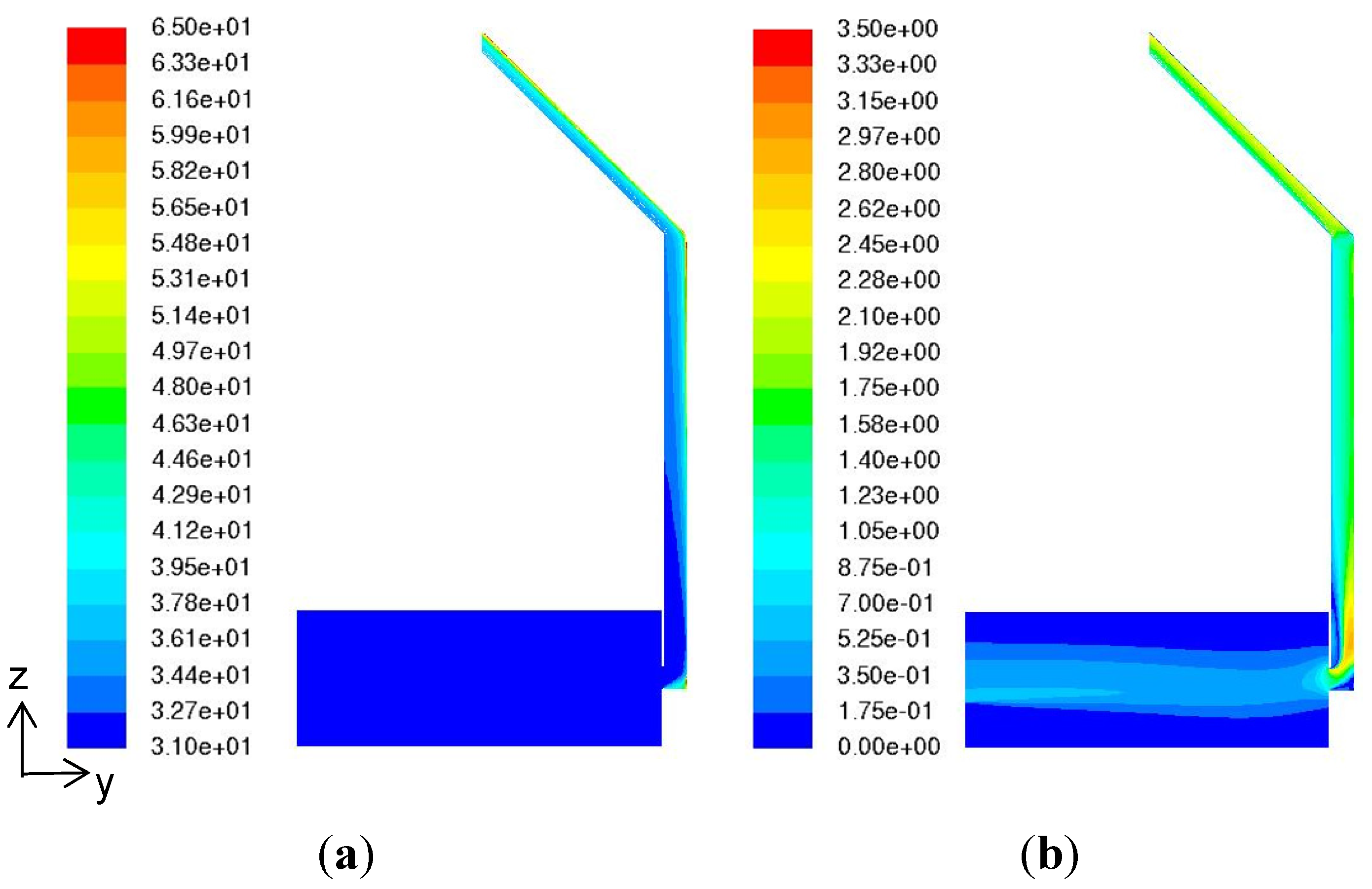
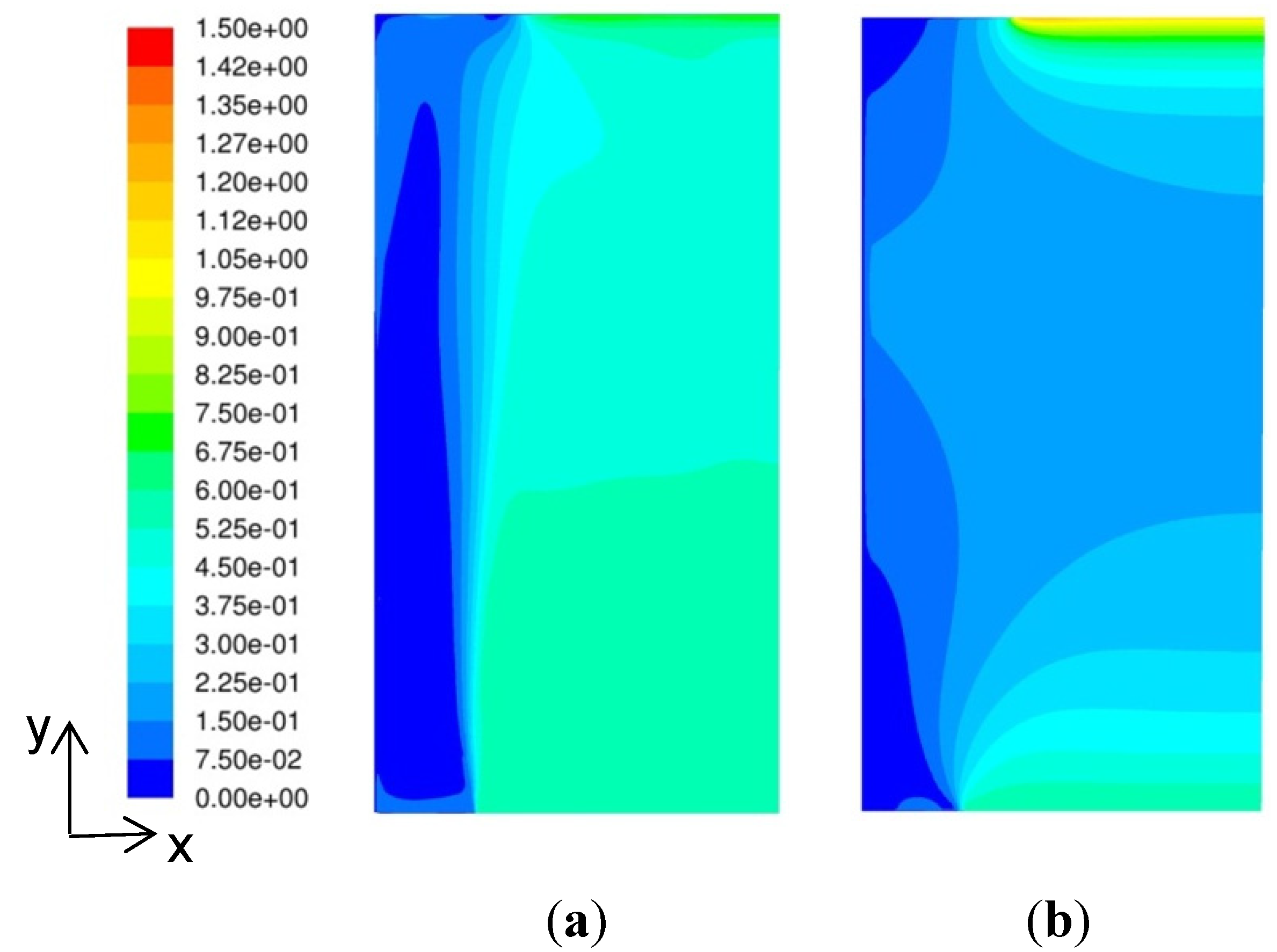
The air temperature along the solar chimney’s mid-plane remains fairly constant at 31.0 °C and increases only after a length of 6.0 m, reaching with a local peak of 37.8 °C at its turning corner. Although the air within the solar chimney is heating up, the thermal energy concentrates near to the external surface and has yet to transfer inwards. It is only after the 6.0 m length that the entire air within the solar chimney heats up, reaching the maximum temperature of 41.0 °C at the outlet. The 10 °C temperature difference within the inlet and outlet of the solar chimney (
Figure 3) proves its operability in the tropics.
From
Figure 3, the air speed fluctuates and first reaches a peak of 2.53 m/s after entering the solar chimney’s inlet due to turbulence from entering a restriction. After travelling for 3.5 m, air speed stabilizes at 1.50 m/s but dips as it nears the turning corner. After the corner, air speed increases and stabilizes at 1.80 m/s.
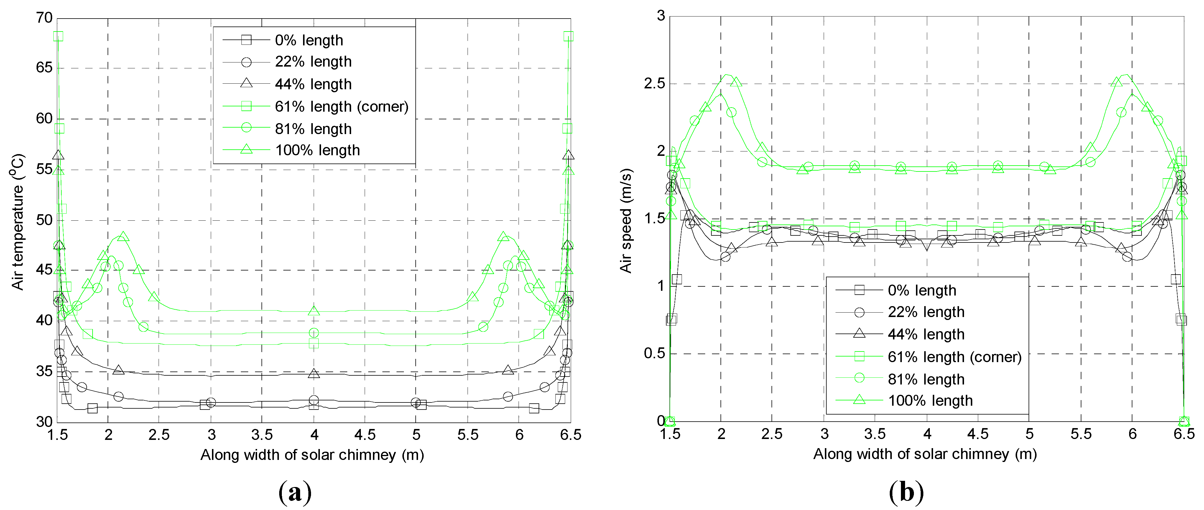
Examining the air temperature and speed along the solar chimney’s width, from
Figure 4, the air temperature and speed are constant along 80% of the width before increasing steeply towards the solar chimney’s walls. This observation repeats along the solar chimney’s length except near to the outlet which is consistent with published literature [
25,
26]. Generally, the air temperature and speed within the solar chimney can be taken as two-dimensional flow.
Figure 3.
(a) Air temperature (°C) mid-plane distribution for base case simulation; (b) Air speed (m/s) mid-plane distribution for base case simulation.
Figure 3.
(a) Air temperature (°C) mid-plane distribution for base case simulation; (b) Air speed (m/s) mid-plane distribution for base case simulation.
Figure 4.
(a) Air temperatures along solar chimney’s width for various mid-length of solar chimney for base case simulation; (b) Air speeds along solar chimney’s width for various mid-length of solar chimney for base case simulation.
Figure 4.
(a) Air temperatures along solar chimney’s width for various mid-length of solar chimney for base case simulation; (b) Air speeds along solar chimney’s width for various mid-length of solar chimney for base case simulation.
4.1.2. Air Temperature and Speed within Interior
From
Figure 3, it is clear that air temperature within the interior remains constant at 31.0 °C. This may be due to the high temperature from the tropics which prevents temperature stratification from occurring within the interior and instead occurs within the solar chimney when the stack height reaches beyond 6.0 m.
The interior air speed generally flows in a straight path across the interior from the fenestration towards the solar chimney’s inlet. Air speed slows down slightly along the path before peaking near the solar chimney’s inlet. The output air speed (averaging on the plane 1.20 m above the ground) reaches 0.40 m/s and no backflow is observed at the fenestration. Air outside this straight path (below and above as well as at its sides) circulates with an average speed of 0.10 m/s, showing that air within the entire interior is moving although there is no air exchange.
4.2. Parameterization Analysis
With the analysis of the base case completed and results obtained similar to published literature, details analysis into the parameterization of the four input parameters (solar chimney’s stack height, depth, width and inlet position) is performed.
4.2.1. Effects of Solar Chimney’s Stack Height
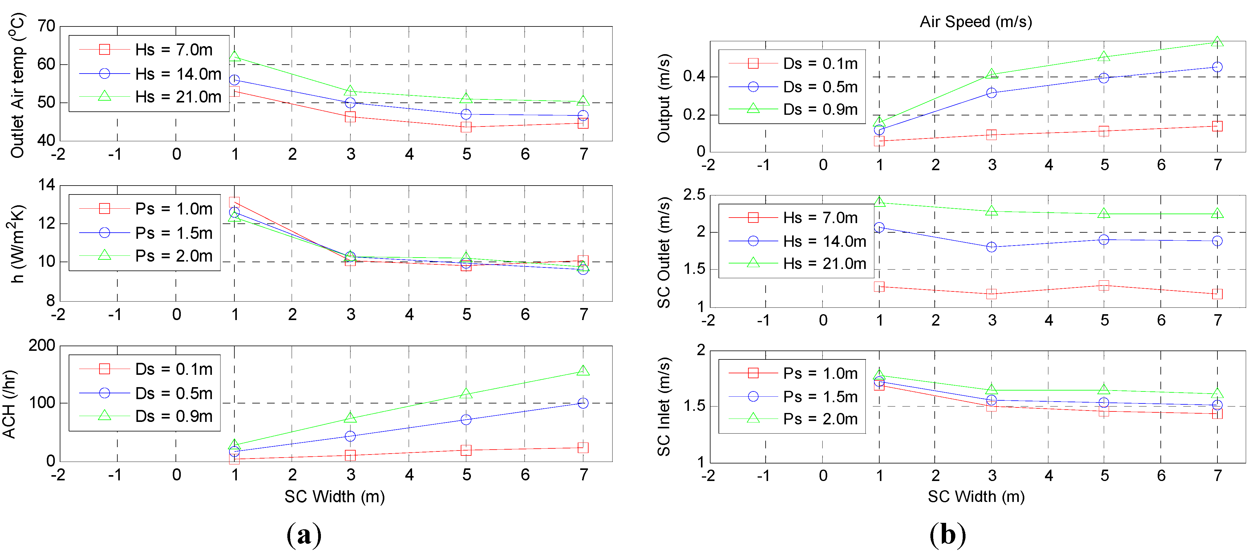
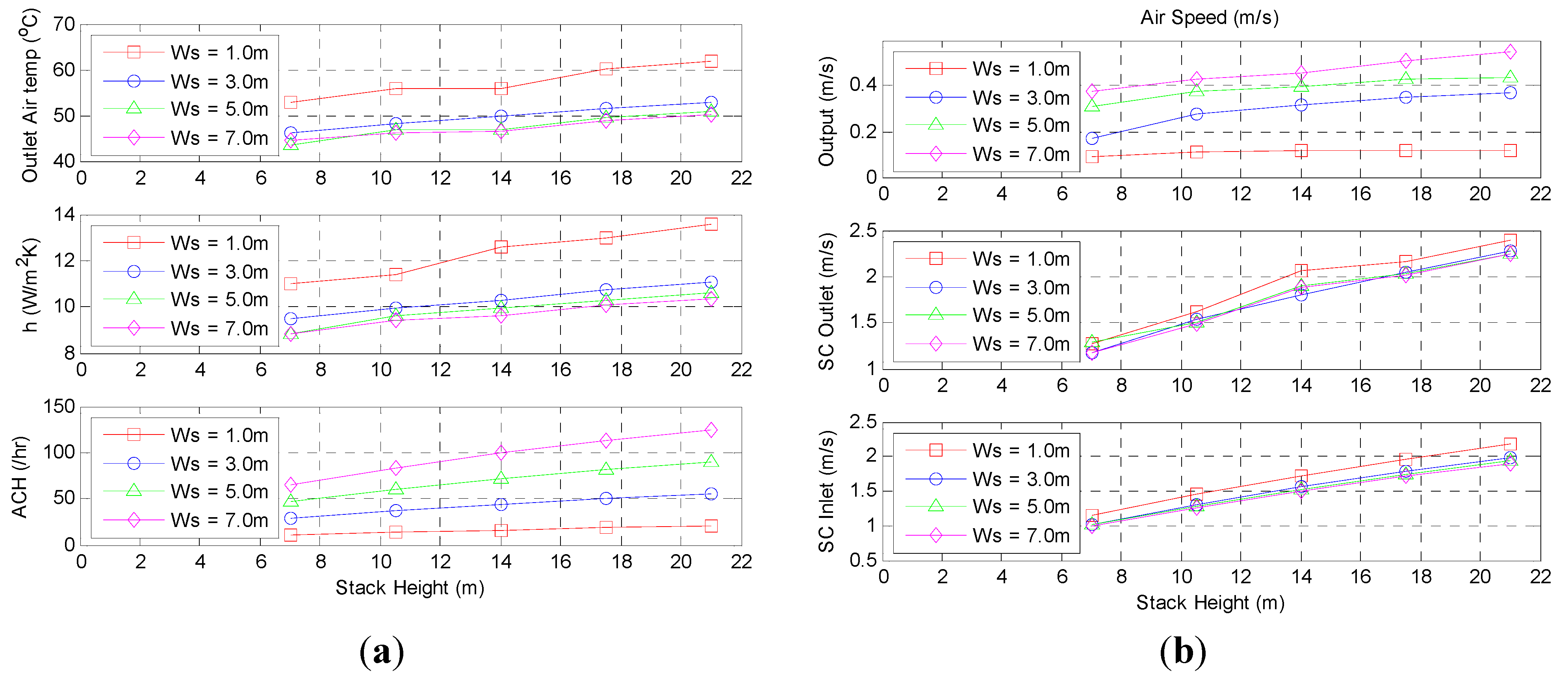
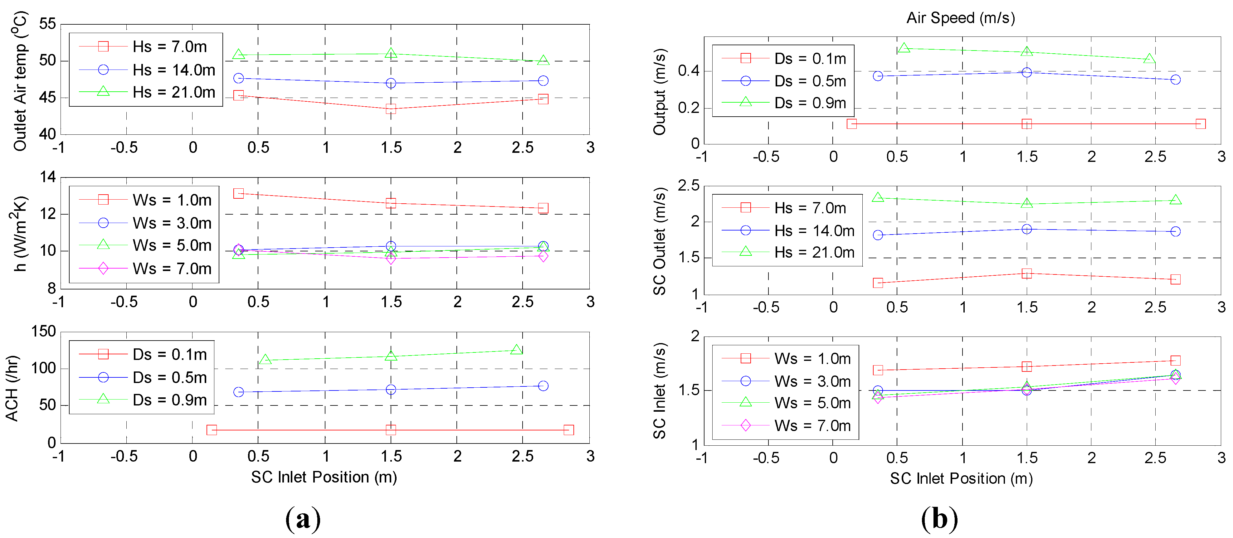
The effects of stack height on the air temperature and speed within the solar chimney and interior are clear, the larger the stack height, the greater the solar chimney outlet air temperature, as seen in
Figure 5. The output air temperature and solar chimney inlet air temperature remain constant at 31.0 °C regardless of the stack height due to the lack of temperature stratification within the interior.
The greater the stack height and corresponding higher air temperature within the solar chimney results in thermal energy being transferred in greater quantity and hence leads to an increase in the heat transfer coefficient. At the same time, this leads to the increase in air speed within both the solar chimney and the interior.
Figure 5.
(a) Air Solar chimney outlet air temperatures, heat transfer coefficients and air change rates with respect to varying solar chimney’s stack height; (b) Output air speeds, solar chimney outlet air speeds and solar chimney inlet air speeds with respect to varying solar chimney’s stack height.
4.2.2. Effects of Solar Chimney’s Depth
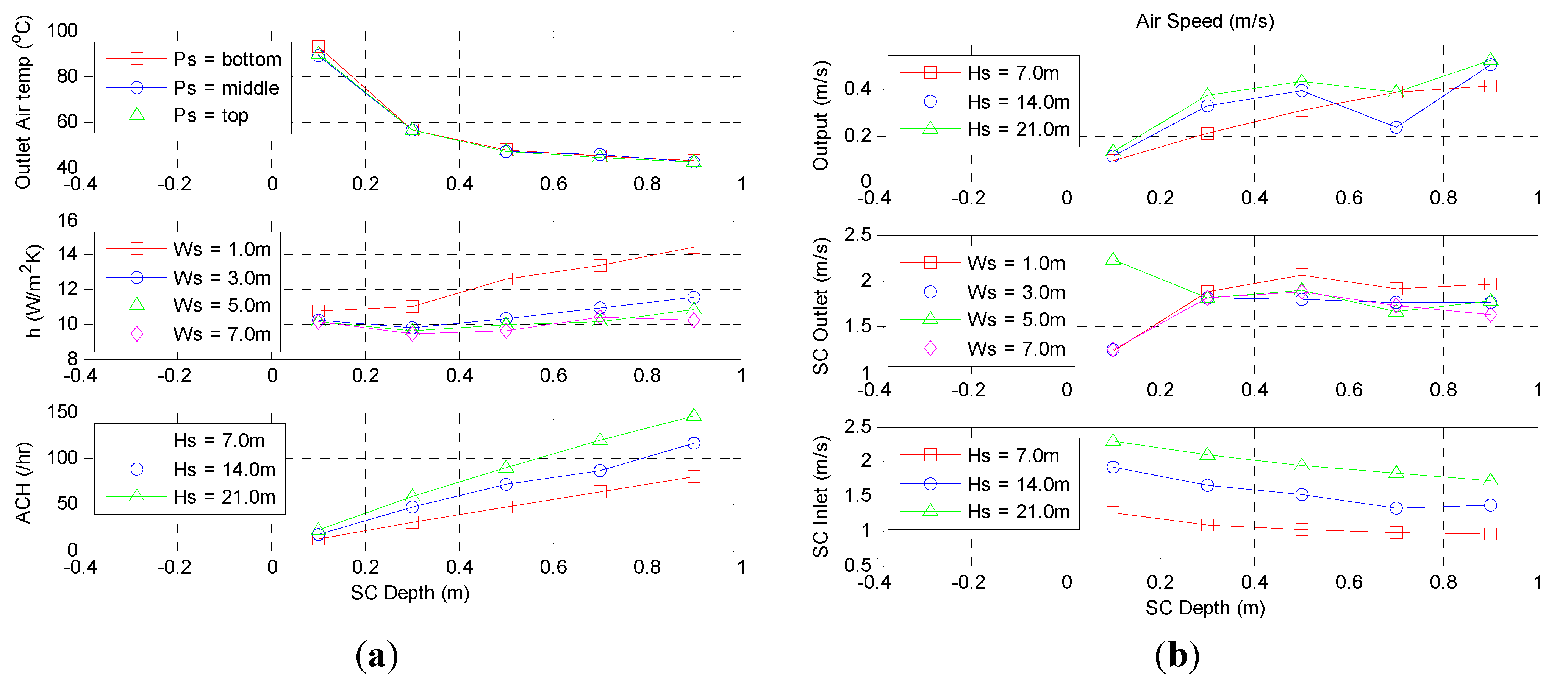
The effects of increasing the solar chimney’s depth influence many aspects. Firstly, the increase in solar chimney’s depth results in an increase in the air volume within the solar chimney. However, when the solar chimney’s depth increases beyond 0.50 m, the ratio of solar chimney’s length to hydraulic diameter drops to less than 15.
Along the solar chimney’s length, below 15 to 20 times of the hydraulic diameter is the region where the thermal boundary layers are still developing and the air volume within the solar chimney is predominantly unheated. This explains why in
Figure 6, the solar chimney outlet air temperature drops significantly from 89.2 °C (ratio of length to hydraulic diameter is 80) at a depth of 0.10 m to 42.1 °C (ratio of length to hydraulic diameter is 10) at a depth of 0.90 m as well as in
Figure 7, where there is a significant drop in the output air speed when the ratio of length to hydraulic diameter is less than 15.
Figure 6.
(a) Solar Chimney outlet air temperatures, heat transfer coefficients and air change rates with respect to varying solar chimney’s depth. (b) Output air speeds, solar chimney outlet air speeds and solar chimney inlet air speeds with respect to varying solar chimney’s depth.
Figure 6.
(a) Solar Chimney outlet air temperatures, heat transfer coefficients and air change rates with respect to varying solar chimney’s depth. (b) Output air speeds, solar chimney outlet air speeds and solar chimney inlet air speeds with respect to varying solar chimney’s depth.
Figure 7.
Output air speed distribution with solar chimney’s depth of (a) 0.50 m and (b) 0.70 m for solar chimney’s stack height of 14.00 m, width of 5.00 m and middle inlet position with corresponding ratio of solar chimney’s length to hydraulic diameter of 17 and 13 respectively.
Figure 7.
Output air speed distribution with solar chimney’s depth of (a) 0.50 m and (b) 0.70 m for solar chimney’s stack height of 14.00 m, width of 5.00 m and middle inlet position with corresponding ratio of solar chimney’s length to hydraulic diameter of 17 and 13 respectively.
4.2.3. Effects of Solar Chimney’s Width
The influence of the solar chimney’s width is similar to the solar chimney’s depth since the wetted perimeter is the combination of the solar chimney’s depth and width. Therefore, the solar chimney outlet air temperature decreases with increasing solar chimney’s width.
However, from
Figure 8, the two-dimensional flow which is independent of the solar chimney’s width is clearly shown from the stabilizing of the heat transfer coefficient as well as the air speed at the solar chimney’s inlet and outlet. This occurs when the solar chimney’s width goes beyond 3.00 m or when the ratio of the stack height to the solar chimney’s width is less 7.
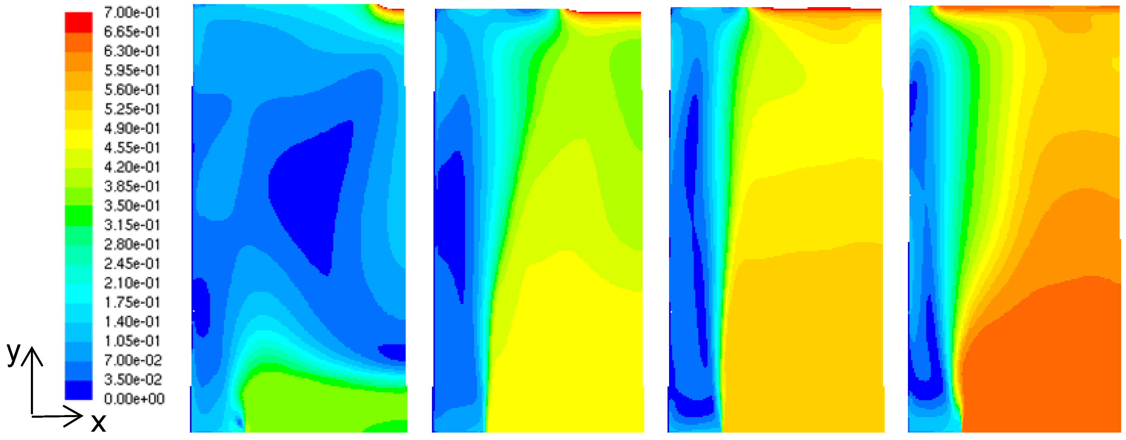
Although the solar chimney is experiencing two-dimensional flow, the air flow within the interior is strongly affected by the solar chimney’s width, as seen by the increase of air change rate and output air speed. For a solar chimney’s depth of 0.90 m and stack height of 14.00 m, the output air speed increases from 0.16 m/s to 0.59 m/s with corresponding solar chimney’s width of 1.00 m and 7.00 m respectively, as seen in
Figure 9.
Figure 8.
(a) Solar chimney outlet air temperatures, heat transfer coefficients and air change rates with respect to varying solar chimney’s width; (b) Output air speeds, solar chimney outlet air speeds and solar chimney inlet air speeds with respect to varying solar chimney’s width.
Figure 8.
(a) Solar chimney outlet air temperatures, heat transfer coefficients and air change rates with respect to varying solar chimney’s width; (b) Output air speeds, solar chimney outlet air speeds and solar chimney inlet air speeds with respect to varying solar chimney’s width.
4.2.4. Effects of Solar Chimney’s Inlet Position
The solar chimney’s inlet position is defined as the height of the mid-plane of its inlet above the ground. As the size of the inlet is equal to the solar chimney’s depth, the inlet position varies with the solar chimney’s depth. On average, the bottom, middle and top position of the inlet are 0.30, 1.50 and 2.65 m above the ground respectively.
From
Figure 10, the solar chimney outlet air temperature, heat transfer coefficient and solar chimney outlet air speed are fairly constant across the various inlet positions. However, the relative constant output air speed is different from literature [
22] where lowering the inlet position to the middle position leads to an increase in output air speed significantly. Closer examination of the output air speed shows that the solar chimney’s inlet position mainly affects the air speed in the localized region around the solar chimney’s inlet.
Figure 9.
Output air speed distribution with respect to varying solar chimney’s width (left to right: 1.00, 3.00, 5.00 and 7.00 m) for solar chimney’s stack height of 14.0 m, depth of 0.50 m and middle inlet position.
Figure 9.
Output air speed distribution with respect to varying solar chimney’s width (left to right: 1.00, 3.00, 5.00 and 7.00 m) for solar chimney’s stack height of 14.0 m, depth of 0.50 m and middle inlet position.
Figure 10.
(a) Solar chimney outlet air temperatures, heat transfer coefficients and air change rates with respect to varying solar chimney’s inlet position; (b) Output air speeds, solar chimney outlet air speeds and solar chimney inlet air speeds with respect to varying solar chimney’s inlet position.
From
Table 2 (where the origin is located at the lower left corner of the interior), the interior air speed beside the solar chimney’s inlet increased from 0.21 m/s in the bottom position to 0.52 m/s and 0.49 m/s in the middle and top position respectively. However, beside the fenestration, the interior air speed was fairly consistent, giving 0.50 m/s, 0.59 m/s and 0.50 m/s in the bottom, middle and top position respectively. It was observed that airflow streamlines only change direction and move towards the solar chimney’s inlet after travelling across the interior. This explains the increase in localized interior air speed which is damped when the output air speed is averaged across the entire plane.
Table 2.
Interior air speed within output plane for solar chimney’s stack height of 17.50 m, depth of 0.50 m and width of 5.00 m with varying solar chimney’s inlet position parameters.
Table 2.
Interior air speed within output plane for solar chimney’s stack height of 17.50 m, depth of 0.50 m and width of 5.00 m with varying solar chimney’s inlet position parameters.
| Coordinates | Air speed (m/s) |
|---|
| Bottom (0.35 m) | Middle (1.50 m) | Top (2.65 m) |
|---|
| (4.0, 2.0, 0.0) | 0.50 | 0.59 | 0.59 |
| (3.0, 2.0, 0.0) | 0.50 | 0.58 | 0.58 |
| (4.0, 2.0, 0.0) | 0.50 | 0.59 | 0.59 |
| (2.0, 2.0, 0.0) | 0.21 | 0.30 | 0.21 |
| (4.0, 4.0, 0.0) | 0.35 | 0.57 | 0.56 |
| (3.0, 4.0, 0.0) | 0.35 | 0.56 | 0.56 |
| (4.0, 4.0, 0.0) | 0.28 | 0.56 | 0.56 |
| (2.0, 4.0, 0.0) | 0.11 | 0.22 | 0.15 |
| (4.0, 6.0, 0.0) | 0.31 | 0.52 | 0.42 |
| (3.0, 6.0, 0.0) | 0.29 | 0.52 | 0.48 |
| (4.0, 6.0, 0.0) | 0.21 | 0.52 | 0.49 |
| (2.0, 6.0, 0.0) | 0.10 | 0.23 | 0.23 |
4.3. Design and Optimization
With the examination of the influences of the four input parameters, their combined effects on the interior air temperature and speed are determined in order to design and optimize the solar chimney. As the output air temperature remains constant regardless of their effects, the multiple linear regressions will be applied on the remaining primary output parameter: output air speed.
Although there are 300 possible cases according to the limits from
Table 1, a first set of 38 cases (the lower and upper limits of the four input parameters) is simulated and modeled, after which the second set of 52 cases (chosen randomly) and the third set of 49 cases (chosen randomly) follow. The combined 139 cases are sufficient in developing the multiple linear regression model as the coefficient of determination has stabilized to two significant figures, a value of 0.99. Hence, the remaining 161 cases are not simulated.
From the test of significance, the power of the inlet position falls within the critical value of −1.96 and 1.96 where the null hypothesis is accepted, indicating that the solar chimney’s inlet position is insignificant within the regression model which is already consistent with earlier observations. Furthermore, the removal of the solar chimney’s inlet position has limited effects on the regression model, as the coefficient of determination remains unchanged.
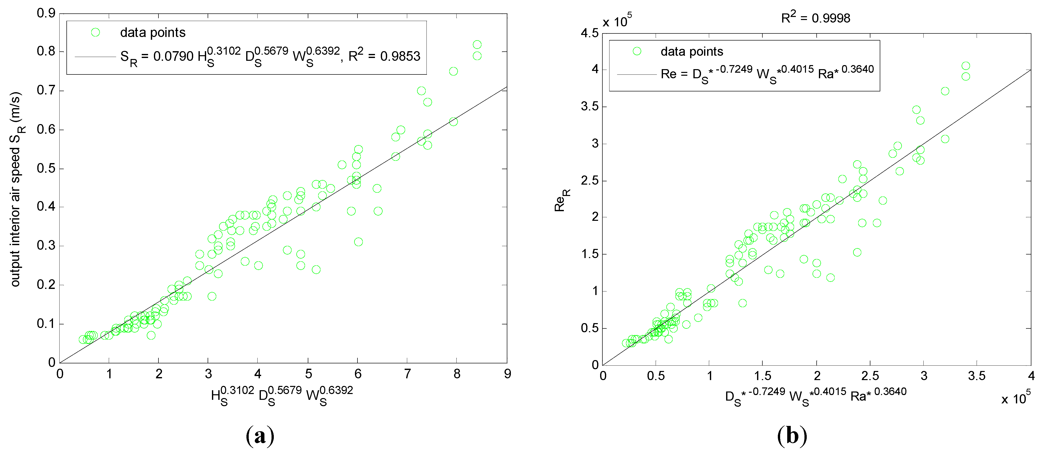
From
Figure 11, the dimensional regression model [Equation (1)] shows that the output air speed increases with increasing solar chimney’s stack height, depth and width, of which the solar chimney’s width has the greatest significance. This is consistent with published literature [
10]:
From sensitivity analysis, the regression model’s reasonable range for the output air speed falls between 0.10 m/s to 1.60 m/s with corresponding solar chimney’s stack height, depth and width within the ranges of 10.00 m to 40.00 m, 0.50 m to 2.00 m and 1.00 m to 10.00 m respectively. Furthermore, it is observed that although the output air speed is small at low solar chimney’s width, it increases at a faster rate comparing to solar chimney’s stack height and depth. Hence, during the design of a solar chimney, it is recommended to first determine its width, which should be as large as possible.
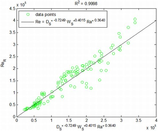
Figure 11.
(a) Dimensional multiple linear regression model for output air speed; (b) Non-dimensional regression model for output Reynolds number.
Figure 11.
(a) Dimensional multiple linear regression model for output air speed; (b) Non-dimensional regression model for output Reynolds number.
The limitation of the dimensional regression model lies in its inability to predict the output air speed if the interior size or solar irradiance change. To overcome this issues, the non-dimensional multiple linear regression model is developed where the solar chimney’s depth, width and inlet position are normalized with its stack height (known as the solar chimney depth ratio, solar chimney width ratio and solar chimney inlet position ratio respectively) while the fourth parameter is the modified heat flux Rayleigh number. The non-dimensional output parameter is the output Reynolds number.
It is important to note that the four non-dimensional input parameters are no longer independent from each other (except for the solar chimney inlet position ratio) as the modified heat flux Rayleigh number employs the hydraulic diameter of the solar chimney, which is derived from the solar chimney’s depth and width:
Similar to the dimensional regression model, the solar chimney inlet position ratio for the interior Reynolds number is found to be within the critical range and hence accepts the null hypothesis. Furthermore, the first constant is found to be within the critical range and accepts its null hypothesis, rendering the constant to take the value of unity [Equation (2)].
The sensitivity analysis shows that the output Reynolds number ranges between 1.6 × 10³ and 8.1 × 10⁶ and increases with increasing solar chimney width ratio and modified heat flux Rayleigh number. However, the output Reynolds number decreases with increasing depth ratio.
5. Conclusions
By varying the four input parameters as well as developing the physical and computational models, 300 cases of employing the solar chimney in the tropics are generated, of which 139 cases are simulated. Grid independency test and convergence analysis are performed to ensure accuracy.
All simulations show that the output air temperature remains constant. Simulation results show that the solar chimney’s width is the most significant factor influencing the output air speed. Results further show that the ratio of solar chimney’s length to hydraulic diameter should be greater than 15 to ensure developed flow and the ratio of solar chimney’s stack height to width should be less than 7 if airflow within the solar chimney is to be two-dimensional.
Among the four input parameters, the solar chimney’s stack height, depth and width have a direct relationship with the output air speed where the greater the solar chimney’s stack height, depth or width, the larger the output air speed. However, the solar chimney’s inlet position is found to have limited influence on the output air speed, although the region near to the solar chimney’s inlet shows an increase in air speed but is damped when the air speed is averaged across the plane. Hence, when the multiple regression models are developed, the solar chimney’s inlet position fails the test of significance, accepts the null hypothesis and hence, is removed from the regression models.
A simple guideline in applying the regression model is to first maximize the solar chimney’s width by defining it as the width of the interior. Next, the solar chimney’s stack height is usually the height of the building although it is possible to construct the solar chimney to be above the beyond the building’s height. Lastly, the solar chimney’s depth is determined from the regression model by allocating the required output air speed.
As mentioned earlier, the volume of the interior space, the size of its fenestrations and the inclination angle of the solar chimney are possible input parameters that may affect the performance of the solar chimney. They are not included within the parameterization study as their dimensions are fixed according to their functional uses. However, these parameters may be included as further investigation although practically, their parameterization ranges may be fairly narrow.


