Spectrally-Selective Photonic Structures for PV Applications

Abstract
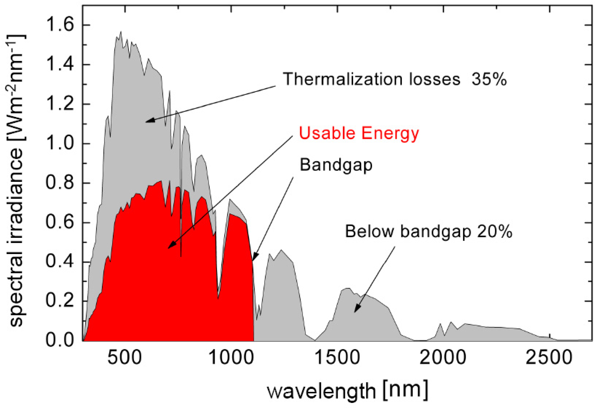
:1. Introduction
- A specific spectral range in which the filter is highly reflective;
- Another spectral range in which the filter is highly transparent. Frequently, these ranges are close-by, so that an additional requirement is
- A steep edge between the both ranges.
2. Spectrally Selective Interference Filters
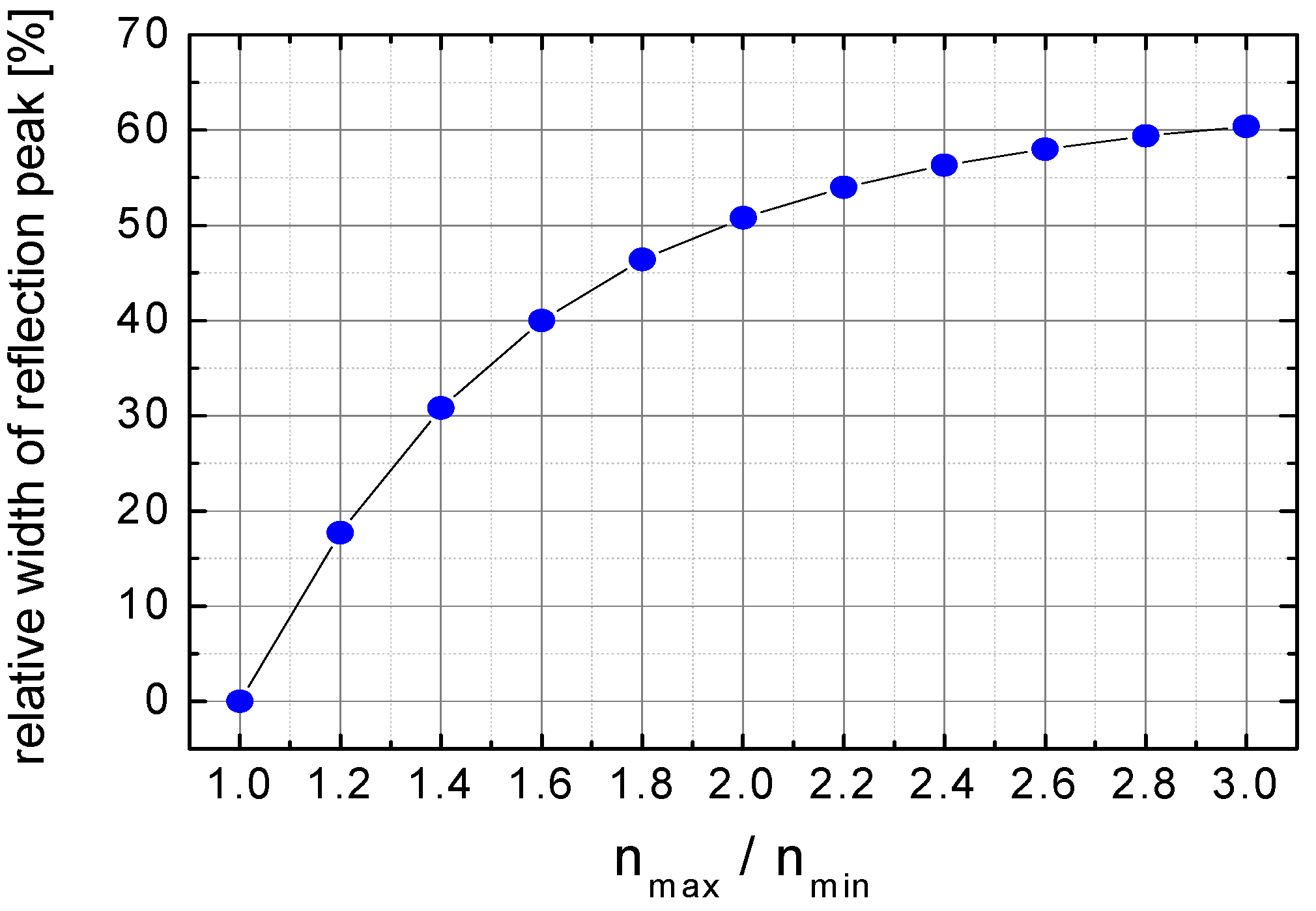
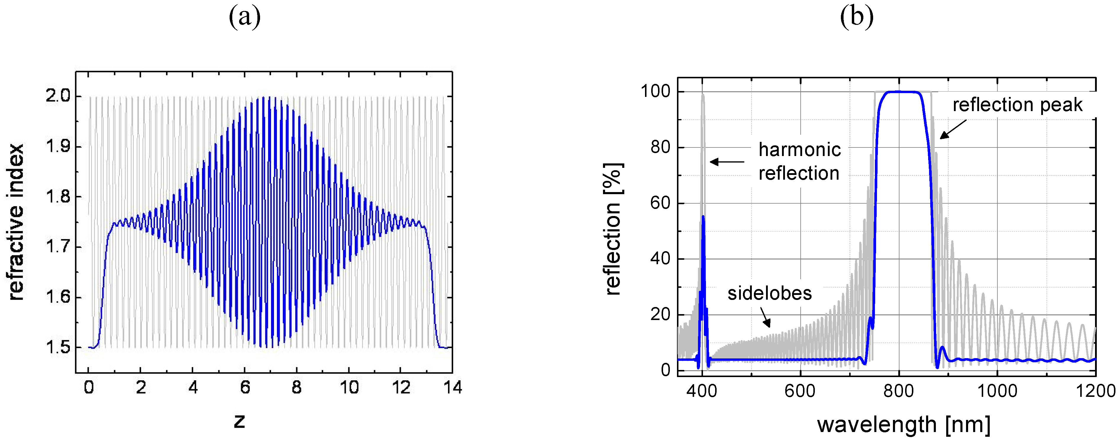
2.1. Rugate Filter


2.2. Edge Filter
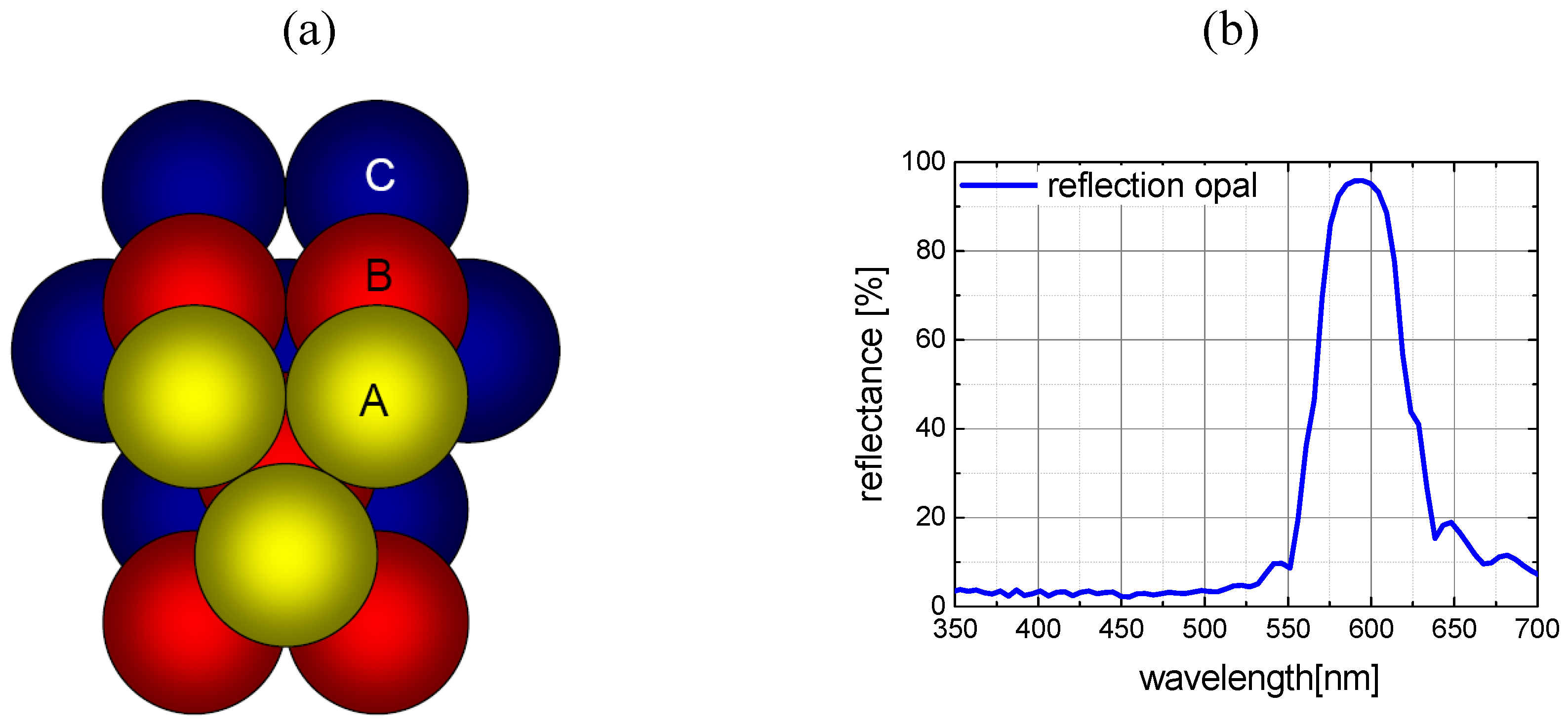
2.3. Opal
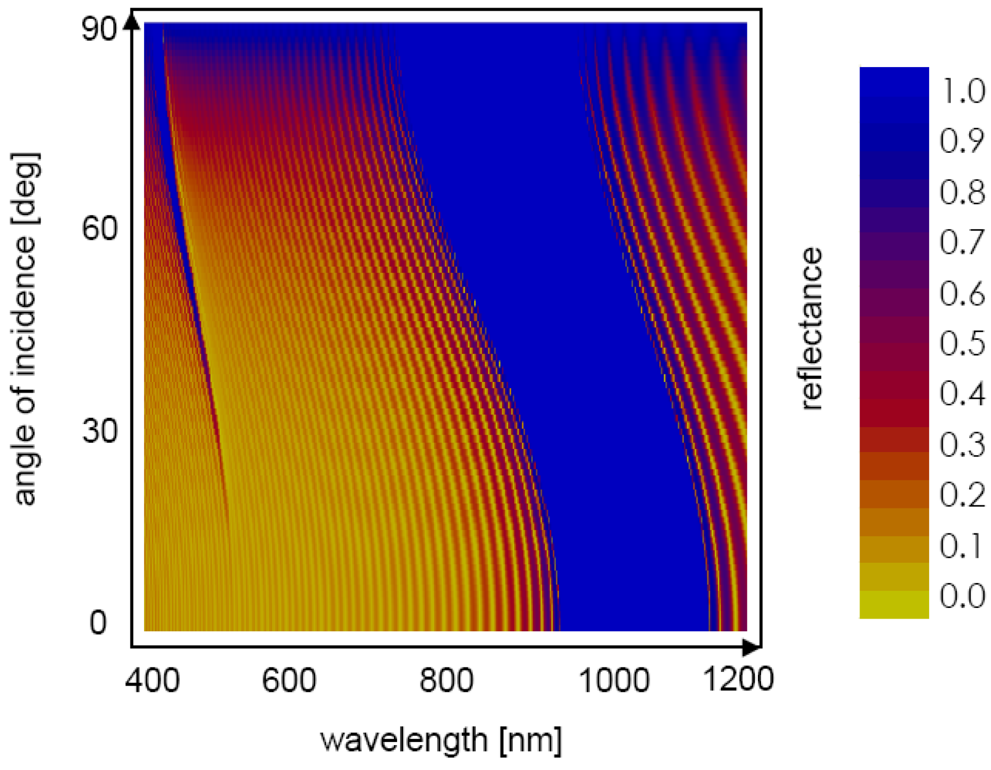
2.4. Angular Dependence

3. Spectrally Selective Filters for PV Concepts with Luminescent Materials
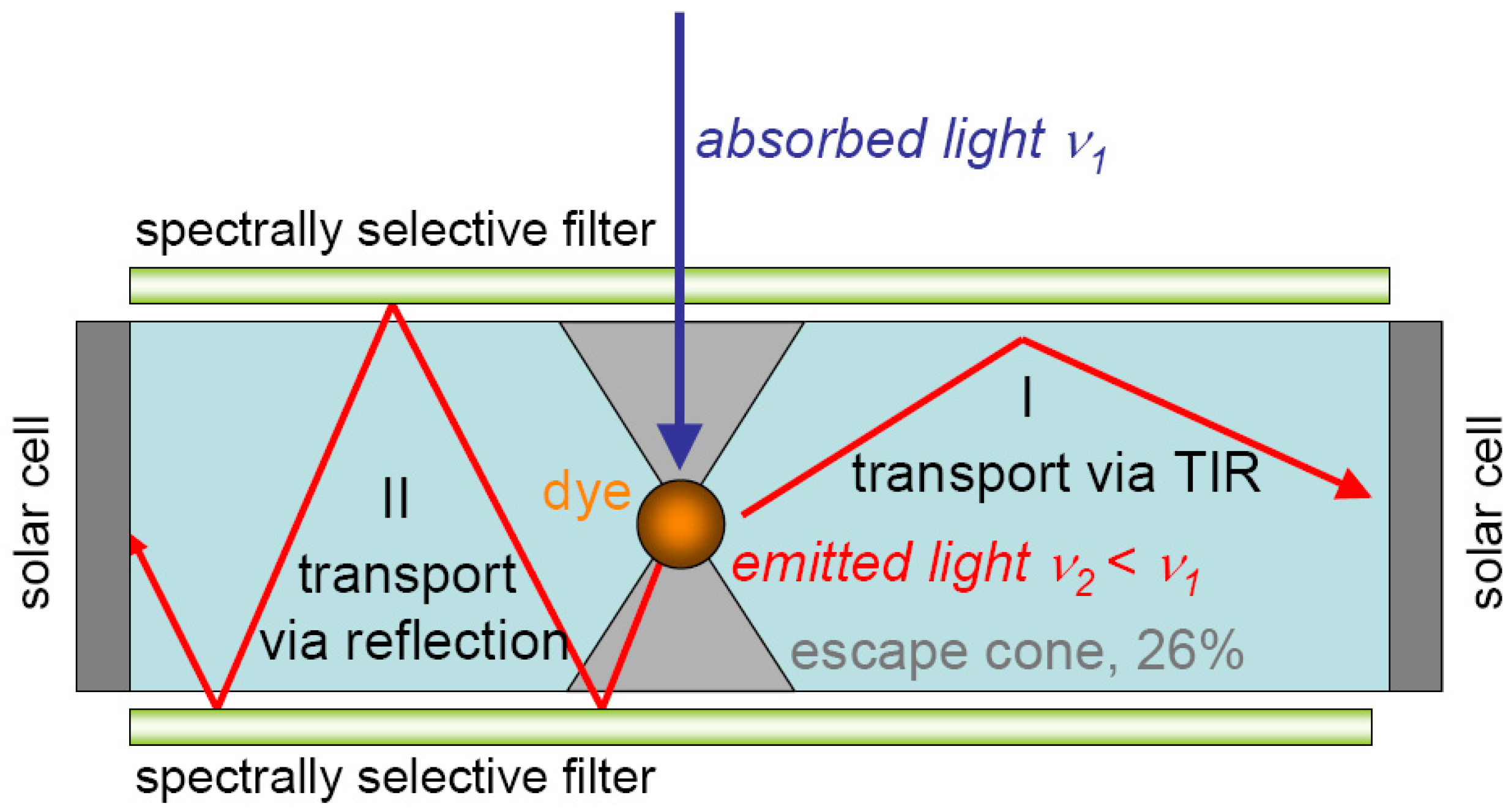
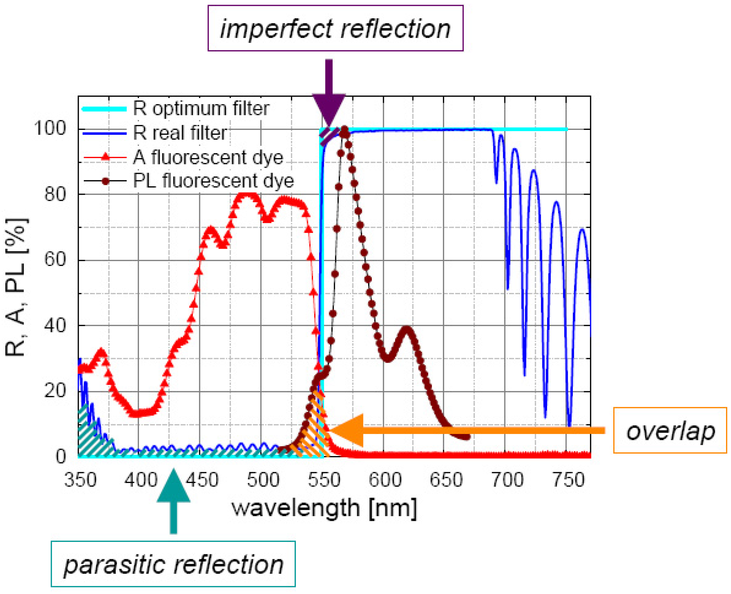
3.1. Fluorescent Concentrators

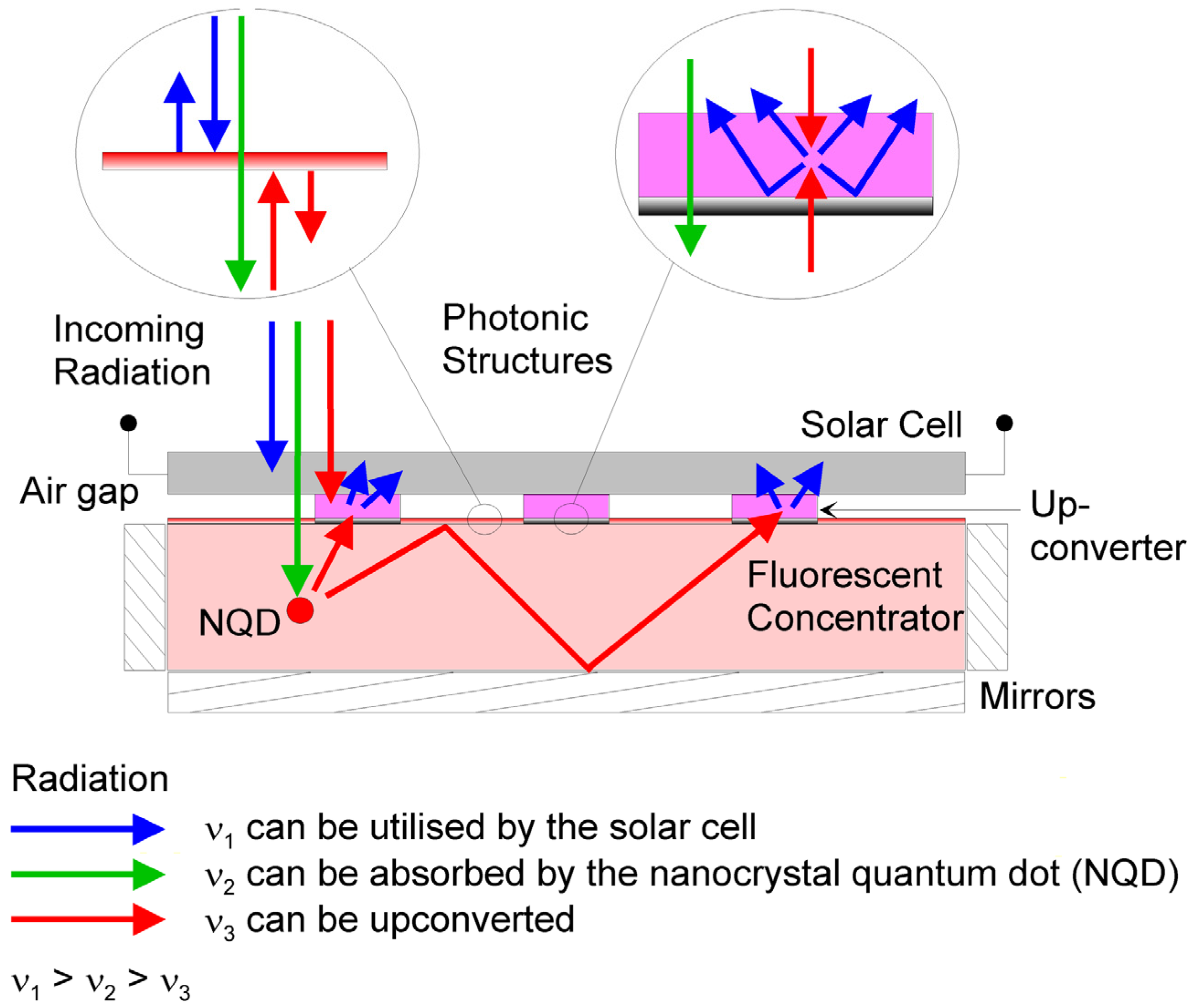
3.2. Upconversion
4. Spectrally Selective Filters for PV Concepts with Spectrum Splitting
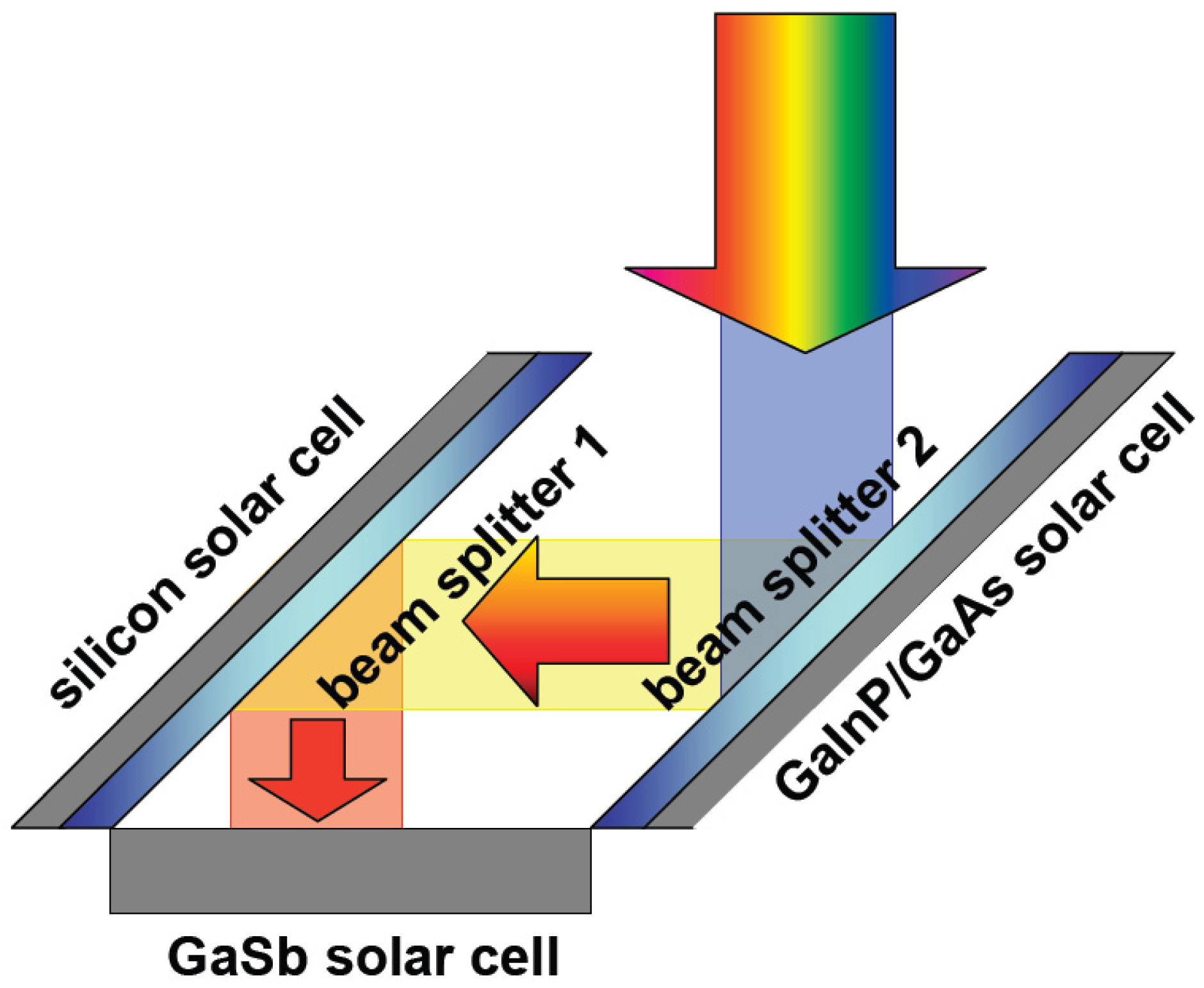
4.1. Spectrum Splitting by Geometrical Assembly


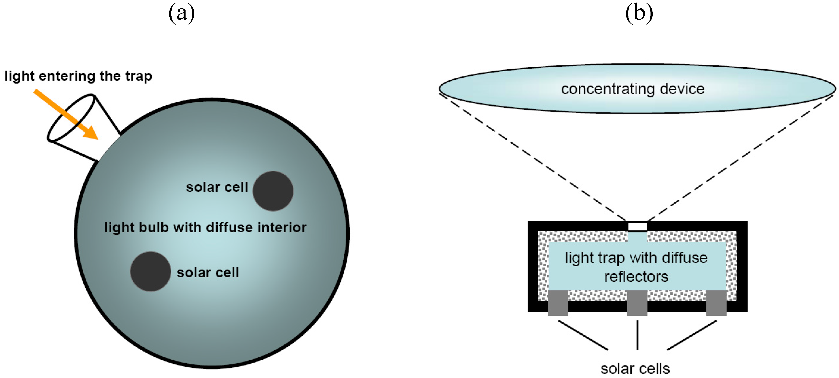
4.2. Spectrum Splitting with Diffuse Light Trap
- The light absorbed by the solar cell for which the light is intended. This contribution depends on the solar cell area Ac1 and the reflection of the filter in front of it Rc1.
- The light absorbed by any other solar cell. This contribution depends on the solar cell area Ac2 and the reflection of the filter in front of it Rc2.
- The light absorbed by the walls of the light trap. This contribution depends on the area not covered by solar cells At and the absorption of the trap Abst.
- The light leaving the trap through the entrance aperture Aent
- The entrance aperture should be small compared to the area covered by the intended solar cell. The relation of aperture area Aent to cell area Ac1 defines the minimum loss.
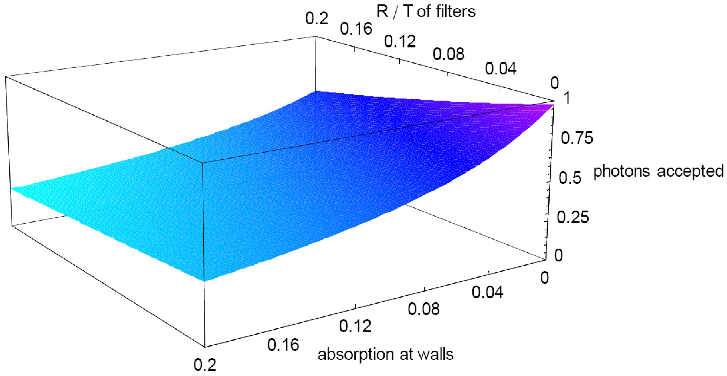
- The quality of the filter should be as high as possible but some imperfections are acceptable. A reduction in filter quality of 1% will roughly reduce the optical efficiency by 1% per solar cell for which the light is not intended.
- The area in the light trap covered by solar cells should not be too small. Otherwise, wall absorption will become more and more important. Even in the moderate setup considered with 30% wall covering, wall absorption of 1% decreases the optical efficiency by ca. 6%. If the wall covering is halved, the reduction already increases to ca. 15% per percent absorption.

4.3. Intermediate Reflectors
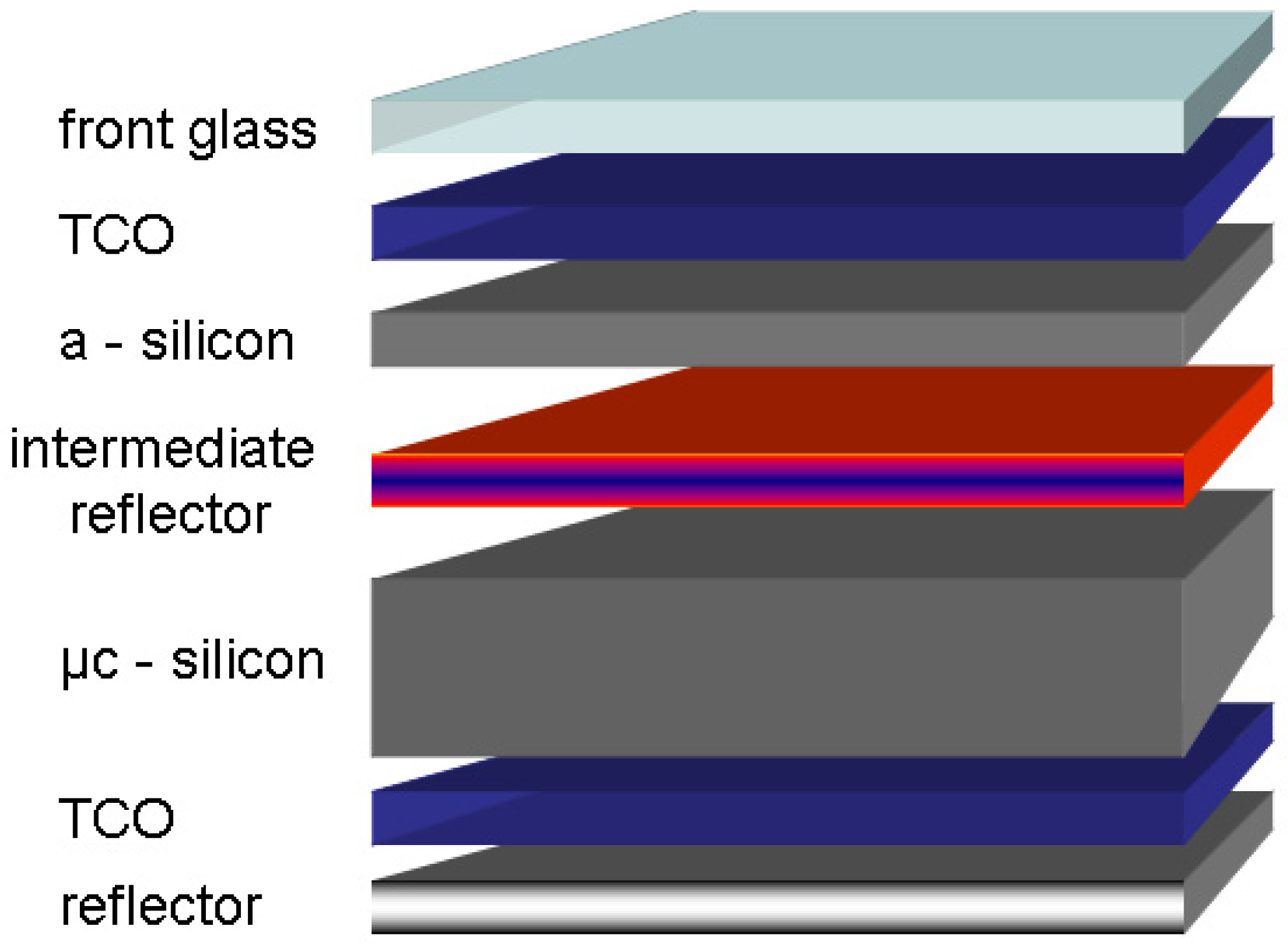
- The current mismatch between the two cells is decreased. Typically, the top cell limits the system current. The intermediate reflector increases the top cell current.
- The voltage of the top cell is higher. Therefore every photon used by the top cell instead of the bottom cell converts a larger fraction of its energy into electricity.
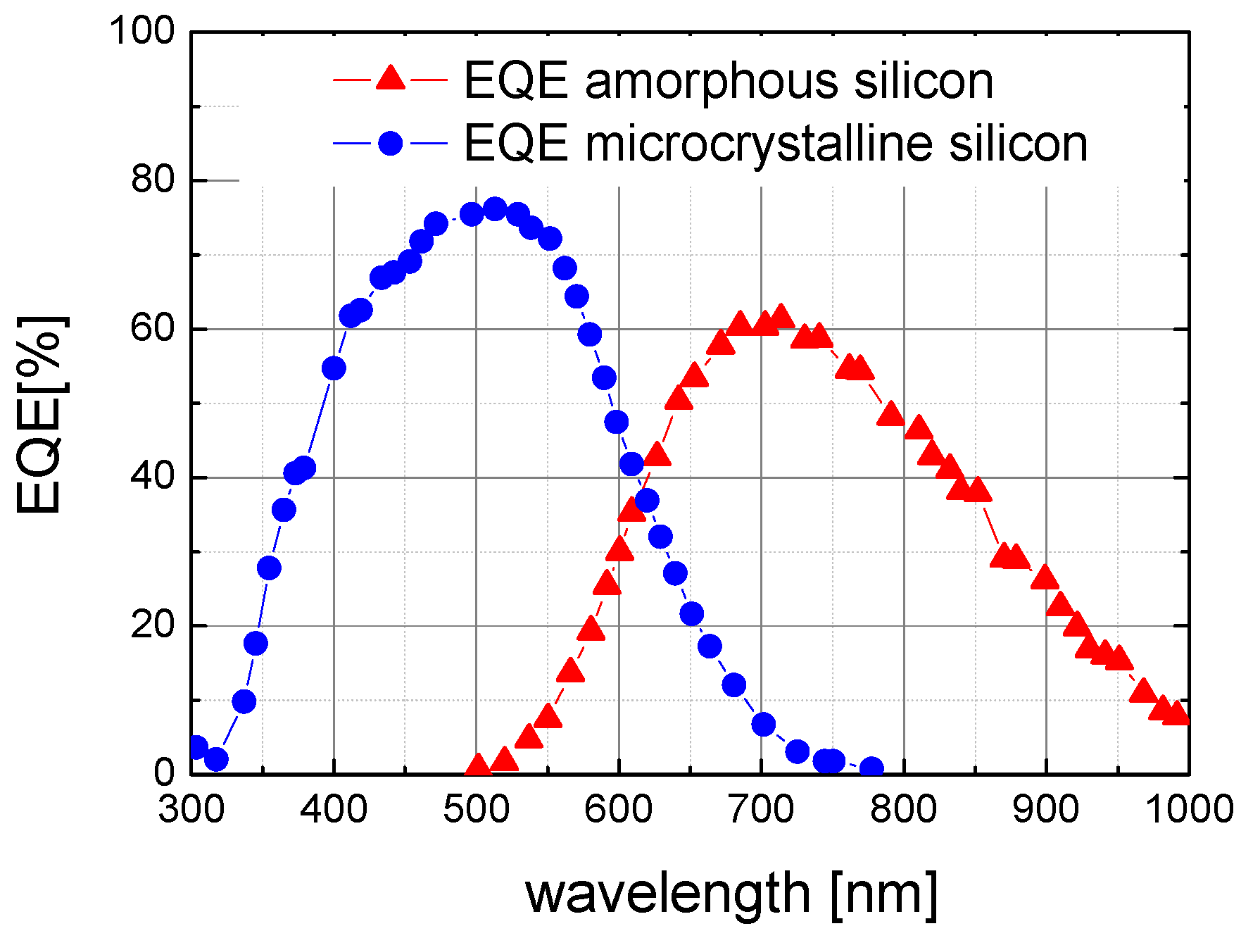
- In order not to lose photons, the filter needs to be transparent for all photons that are used more beneficially by the bottom cell than by the top cell.
- The filter has to reflect exactly the number of photons that is required for current matching. The filter therefore does not need a certain very high reflection, but the reflection characteristic needs to be matched to the solar spectrum and the quantum efficiency [56].
- As the tandem is connected in series, the filter needs to be sufficiently electrically conductive. This demand is the most special one, as typical optical filters do not need this property.
5. Summary
Acknowledgments
References and Notes
- Green, M.A. High Efficiency Silicon Solar Cells; Trans Tech Publications: Aedermannsdorf, Switzerland, 1987; pp. 181–183. [Google Scholar]
- Wang, A.; Zhao, J.; Green, M.A. 24% efficient silicon solar cells. Appl. Phys. Lett. 1990, 57, 602–604. [Google Scholar] [CrossRef]
- Gordon, J.M. Concentrator Optics. In Concentrator Photovoltaics; Luque, A., Andreev, A., Eds.; Springer Verlag: Berlin, Germany, 2007; pp. 113–133. [Google Scholar]
- Burgess, E.L.; Pritchard, D.A. Performance of a one kilowatt concentrator photovoltaic array utilizing active cooling. In Proceedings of the 13th Photovoltaic Specialists Conference, New York, NY, USA, June 1978; pp. 1121–1124.
- Joannopoulos, J.D.; Meade, R.D.; Winn, J.N. Photonic Crystals Molding the Flow of Light; Princeton University Press: Princeton, NJ, USA, 1995; pp. 8–45. [Google Scholar]
- Southwell, W.H.; Hall, R.L. Rugate filter sidelobe suppression using quintic and Rugated quintic matching layers. Appl. Opt. 1988, 28, 2949–2951. [Google Scholar] [CrossRef]
- Lim, S.; Ryu, J.; Wager, J.; Plant, T. Rugate filters grown by plasma-enhanced chemical vapor deposition. Thin Solid Films 1994, 245, 141–145. [Google Scholar] [CrossRef]
- Macleod, H.A. Thin-Film Optical Filters, 3rd ed.; Institute of Physics Publishing: Philadelphia, PA, USA, 2001; pp. 11–32. [Google Scholar]
- Sullivan, B.T.; Dobrowolski, J.A. Implementation of a numerical needle method for thin-film design. Appl. Opt. 1996, 35, 5484–5492. [Google Scholar] [CrossRef] [PubMed]
- Sözüer, H.S.; Haus, J.W.; Inguva, R. Photonic bands: Convergence problems with the plane-wave method. Phys. Rev. B: Condens. Matter Mater. Phys. 1992, 45, 13962–13972. [Google Scholar] [CrossRef]
- Gajiev, G.M.; Golubev, V.G.; Kurdyukov, D.A.; Medvedev, A.V.; Pevtsov, A.B.; Sel’kin, A.V.; Travnikov, V.V. Bragg reflection spectroscopy of opal-like photonic crystals. Phys. Rev. B: Condens. Matter Mater. Phys. 2005, 72, 205115:1–205115:9. [Google Scholar] [CrossRef]
- Peters, M.; Goldschmidt, J.C.; Kirchartz, T.; Bläsi, B. The photonic light trap – improved light traping in solar cells by angularly selective filters. Sol. Energy Mater. Sol. Cells 2009, 93, 1721–1727. [Google Scholar] [CrossRef]
- Imenes, A.G.; Buie, D.; McKenzie, D. The design of broadband, wide-angle interference filters for solar concentrating systems. Sol. Energy Mater. Sol. Cells 2006, 90, 1579–1606. [Google Scholar] [CrossRef]
- Weber, W.H.; Lambe, J. Luminescent greenhouse collector for solar radiation. Appl. Opt. 1976, 15, 2299–2300. [Google Scholar] [CrossRef] [PubMed]
- Goetzberger, A.; Greubel, W. Solar energy conversion with fluorescent collectors. Appl. Phys. 1977, 14, 123–139. [Google Scholar] [CrossRef]
- Wittwer, V.; Heidler, K.; Zastrow, A.; Gotzberger, A. Theory of fluorescent planar concentrators and experimental results. J. Lumin. 1981, 24/25, 873–876. [Google Scholar] [CrossRef]
- Zastrow, A. Physikalische Analyse der Energieverlustmechanismen in Fluoreszenz-konzentratoren; Dissertation, Ùniversität Freiburg: Freiburg, Germany, 1981. [Google Scholar]
- Richards, B.S.; Shalav, A.; Corkish, R.P. A low escape-cone loss luminescent solar concentrator. In Proceedings of the 19th European Photovoltaic Solar Energy Conference, Paris, France, June 2004; pp. 113–116.
- Glaeser, G.C.; Rau, U. Collection and conversion properties of photovoltaic fluorescent concentrators with photonic band stop filters. In Photonics for Solar Energy Systems (Proceedings Volume); Gombert, A., Ed.; SPIE: Bellingham, WA, USA, 2006. [Google Scholar]
- Luque, A.; Martı´, A.; Cuadra, L.; Algora, C.; Wahnon, P.; Sala, G.; Benitez, P.; Bett, A.W.; Gombert, A.; Andreev, V.M.; Jassaud, C.; Van Roosmalen, J.A.M.; Alonso, J.; Raüber, A.; Strobel, G.; Stolz, W.; Bitnar, B.; Stanley, C.; Conesa, J.C.; Van Sark, W.; Barnham, K.; Danz, R.; Meyer, T.; Luque-Heredia, I.; Kenny, R.; Christofides, C. Fullspectrum: A new PV wave making more efficient use of the solar spectrum. In Proceedings of the 19th European Photovoltaic Solar Energy Conference, Paris, France, June 2004; pp. 336–339.
- Van Roosmalen, J.A.M. Molecular-based concepts in PV towards full spectrum utilization. Semiconductors 2004, 38, 970–975. [Google Scholar] [CrossRef]
- Goldschmidt, J.C.; Peters, M.; Hermle, M.; Glunz, S.W. Characterizing the light guiding of fluorescent concentrators. J. Appl. Phys. 2009, 105, 114911:1–114911:9. [Google Scholar] [CrossRef]
- Richards, B.S.; Shalav, A. The role of polymers in the luminescence conversion of sunlight for enhanced solar cell performance. Synth. Met. 2005, 154, 61–64. [Google Scholar] [CrossRef]
- Rau, U.; Einsele, F.; Glaeser, G.C. Efficiency limits of photovoltaic fluorescent collectors. Appl. Phys. Lett. 2005, 87, 171101:1–171101:3. [Google Scholar]
- Glaeser, G.C.; Rau, U. Collection and conversion properties of photovoltaic fluorescent concentrators with photonic band Stopp filters. In Proceedings of SPIE 2006, San Jose, CA, USA, January 2006. [CrossRef]
- Goldschmidt, J.C.; Peters, M.; Löper, P.; Schultz, O.; Dimroth, F.; Glunz, S.W.; Gombert, A.; Willeke, G. Advanced fluorescent concentrator system design. In Proceedings of the 22nd European Photovoltaic Solar Energy Conference, Milan, Italy, September 2007; pp. 608–612.
- Danos, L.; Kittidachachan, P.; Meyer, T.J.J.; Greef, R.; Markvart, T. Characterisation of fluorescent collectors based on solid, liquid and langmuir blodget (LB) films. In Proceedings of the 21st European Photovoltaic Solar Energy Conference, Dresden, Germany, September 2006; pp. 443–446.
- Debije, M.G.; Broer, D.J.; Bastiaansen, C.W.M. Effect of dye alignment on the output of a luminescent solar concentrator. In Proceedings of the 22nd European Photovoltaic Solar Energy Conference, Milan, Italy, September 2007; pp. 87–89.
- Slooff, L.H.; Budel, T.; Burgers, A.; Bakker, N.; Büchtemann, A.; Danz, R.; Meyer, T.; Meyer, A. The luminescent concentrator: stability issues. In Proceedings of the 22nd European Photovoltaic Solar Energy Conference, Milan, Italy, September 2007; pp. 584–588.
- Peters, M.; Goldschmidt, J.C.; Löper, P.; Bläsi, B.; Gombert, A. The effect of photonic structures on the light guiding efficiency of fluorescent concentrators. J. Appl. Phys. 2009, 105, 014909:1–014909:10. [Google Scholar]
- Goldschmidt, J.C.; Peters, M.; Bösch, A.; Helmers, H.; Dimroth, F.; Glunz, S.W.; Willeke, G. Increasing the efficiency of fluorescent concentrator systems. Sol. Energy Mater. Sol. Cells 2009, 93, 176–182. [Google Scholar] [CrossRef]
- Trupke, T.; Shalav, A.; Richards, B.S.; Würfel, P.; Green, M.A. Efficiency enhancement of solar cells by luminescent up-conversion of sunlight. Sol. Energy Mater. Sol. Cells 2006, 90, 3327–3338. [Google Scholar] [CrossRef]
- Richards, B.S.; Shalav, A. Enhancing the near-infrared spectral response of silicon optoelectronic devices via up-conversion. IEEE Trans. Electr. Devices 2007, 54, 2679–2684. [Google Scholar] [CrossRef]
- Krämer, K.W.; Biner, D.; Frei, G.; Güdel, H.U.; Hehlen, M.P.; Lüthi, S.R. Hexagonal sodium yttrium fluoride based green and blue emitting upconversion phosphors. Chem. Mater. 2004, 16, 1244–1251. [Google Scholar] [CrossRef]
- Strümpel, C.; McCann, M.; del Cañizo, C.; Tobías, I.; Fath, P. Erbium-doped up-converters on silicon solar cells: Assessments of potentials. In Proceedings of the 20th EUPVSEC, Barcelona, Spain, June 2005.
- Goldschmidt, J.C.; Löper, P.; Fischer, S.; Janz, S.; Peters, M.; Glunz, S.W.; Willeke, G.; Lifshitz, E.; Krämer, K.; Biner, D. Advanced upconverter systems with spectral and geometric concentration for high upconversion efficiencies. In Proceedings of IUMRS-ICEM08, Sydney, Australia, July 2008; pp. 307–311.
- Goldschmidt, J.C.; Löper, P.; Peters, M. Bundesrepublik Deutschland, Fraunhofer-Gesellschaft zur Förderung der angewandten Forschung e.V. Deutsches Patent 102007,045,546, 2009. [Google Scholar]
- Bhawalkar, J.D.; He, G.S.; Park, C.K.; Zhao, C.F.; Ruland, G.; Prasdan, P.N. Efficient two-photon pumped green upconverted cavity lasing in a new dye. Opt. Commun. 1996, 124, 33–37. [Google Scholar] [CrossRef]
- Lifshitz, E.; Brumer, M.; Kigel, A.; Sashchiuk, A.; Bashouti, M.; Sirota, M.; Galun, E.; Burshtein, Z.; Le Quang, A.Q.; Ledoux-Rak, I.; Zyss, J. Air-stable PbSe/PbS and PbSe/PbSexS1-x core-shell nanocrystals quantum dots and their applications. J. Phys. Chem. B 2006, 110, 25356–25365. [Google Scholar] [CrossRef] [PubMed]
- Shockley, W.; Queisser, H.J. Detailed balance limit of efficiency of p-n junction solar cells. J. Appl. Phys. 1961, 32, 510–519. [Google Scholar] [CrossRef]
- Moon, R.L.; James, L.W.; Vander Plas, H.A.; Yep, T.O.; Antypas, G.A. Multigap solar cell requirements and the performance of AlGaAs and Si cells in concentrated sunlight. In Proceedings of the 13th IEEE Photovoltaic Specialists Conference, New York, NY, USA; 1978; pp. 859–867. [Google Scholar]
- Barnett, A.; Kirkpatrick, D.; Honsberg, C.; Moore, D.; Wanlass, M.; Emery, K.; Schwartz, R; Carlson, D.; Bowden, S.; Aiken, D. Very high efficiency solar cell modules. Prog. Photovoltaics: Res. Appl. 2009, 17, 75–83. [Google Scholar] [CrossRef]
- Fraas, L.M.; Avery, J.E.; Huang, H.X.; Minkin, L.; Shifman, E. Demonstration of a 33% efficient cassegrainian solar module. In Proceedings of the 4th World Conference on Photovoltaic Energy Conversion, Hawaii, HI, USA, May 2006; pp. 679–682.
- Vincenzi, D.; Busato, A.; Stefancich, M.; Martinelli, G. Concentrating PV system based on spectral separation of solar radiation. Physica. Status Solidi: A 2009, 206, 375–378. [Google Scholar] [CrossRef]
- Bielawny, A.; Miclea, P.T.; Rhein, A.; Wehrspohn, R.B.; Van Riesen, S.; Glunz, S. Dispersive elements for spectrum splitting in solar cell applications. In Proceedings of SPIE 2006, San Jose, CA, USA, January 2006; p. 619704.
- Groß, B.; Peharz, G.; Siefer, G.; Peters, M.; Gandy, T. Four-junction spectral beam splitting photovoltaic receiver with high optical efficiency. Prog. Photovoltaics: Res. Appl. 2009, (in press). [Google Scholar]
- Ortabasi, U. First experiences with a multi-bandgap photovoltaic cavity converter (PVCC) module for ultimate solar-to-electricity conversion efficiency. In Proceedings of the 19th European Photovoltaic Solar Energy Conference, Paris, France, June 2004; pp. 2256–2560.
- Imenes, A.G.; Mills, D.R. Spectral beam splitting technology for increased conversion efficiency in solar concentrating systems: a review. Sol. Energy Mater. Sol. Cells 2004, 84, 19–69. [Google Scholar] [CrossRef]
- Minano, J.C.; Luque, A.; Tobias, I. Light-confining cavities for photovoltaic applications based on the angular-spatial limitation of the escaping beam. Appl. Opt. 1992, 31, 3114–3122. [Google Scholar] [CrossRef] [PubMed]
- Goetzberger, A.; Goldschmidt, J.C.; Peters, M.; Löper, P. Light trapping, a new approach to spectrum splitting. Sol. Energy Mater. Sol. Cells 2008, 92, 1570–1578. [Google Scholar] [CrossRef]
- De Vos, A. Detailed balance limit of the efficiency of tandem solar cells. J. Phys. D: Appl. Phys. 1980, 12, 839–846. [Google Scholar] [CrossRef]
- Repmann, T. Investigations on the current matching of highly efficient tandem solar cells based on amorphous and microcrystalline silicon. In Proceedings of 3rd World Conference on Photovoltaic Energy Conversion, Osaka, Japan, May 2003; pp. 1843–1846.
- Wieder, S.; Rech, B.; Roschek, T.; Müller, J.; Wagner, H. Proceedings of the E-PVSEC, Glasgow, UK, May 2000; p. 561.
- Steinhauser, J.; Shah, A.; Ballif, C.; Domin´e, D.; Bailat, J. Micromorph solar cell optimization using a ZnO layers as intermediate reflector. In Conference Record of the 2006 IEEE 4th World Conference on Photovoltaic Energy Conversion, Hawaii, HI, USA, May 2006; pp. 1465–1468.
- Dominé, D.; Steinhauser, J.; Feitknecht, L.; Shah, A.; Ballif, C. Effect of ZnO layer as intermediate reflector in micromorph solar cells. In Proceedings of the 20th EU Photovoltaic Solar Energy Conference, Barcelona, Spain, June 2005; pp. 1600–1603.
- Bielawny, A.; Üpping, J.; Wehrspohn, R. Spectral properties of intermediate reflectors in micromorph tandem cells. Sol. Energy Mater. Sol. Cells 2009, 93, 1909–1912. [Google Scholar] [CrossRef]
- Yamamoto, K.; Nakajima, A.; Yoshimi, M.; Sawada, T.; Fukuda, S.; Suezaki, T.; Ichikawa, M.; Koi, Y.; Goto, M.; Meguro, T.; Matsuda, T.; Sasaki, T.; Tawada, Y. High efficiency thin film silicon hybrid cell and module with newly developed innovative interlayer. In Conference Record of the 2006 IEEE 4th World Conference on Photovoltaic Energy Conversion, Hawaii, HI, USA, May 2006; pp. 1489–1492.
- Bielawny, A.; Üpping, J.; Miclea, P.T.; Wehrspohn, R.B.; Rockstuhl, C.; Lederer, F.; Peters, M.; Steidl, L.; Zentel, R.; Lee, S.; Knez, M.; Lambertz, A.; Carius, R. 3d photonic crystal intermediate reflector for micromorph thin-film tandem solar cell. Phys. Stat. Sol. B 2008, 205, 2796–2810. [Google Scholar] [CrossRef]
- Shvarts, M.Z.; Chosta, O.I.; Kochnev, I.V; Lantratov, V.M.; Andreev, V.M. Radiation resistant AlGaAs/GaAs concentrator solar cells with internal Bragg reflector. Sol. Energy Mater. Sol. Cells 2001, 68, 105–122. [Google Scholar]
- Krisl, M.E.; Sanchez, J.; Sachs, I.M. Thin film coatings for improved coverglass thermal characteristics. In Proceedings of the 18th IEEE Photovoltaic Specialists Conference, Las Vegas, NV, USA, October 1985; pp. 692–696.
© 2010 by the authors; licensee Molecular Diversity Preservation International, Basel, Switzerland. This article is an open-access article distributed under the terms and conditions of the Creative Commons Attribution license (http://creativecommons.org/licenses/by/3.0/).
Share and Cite
Peters, M.; Goldschmidt, J.C.; Löper, P.; Groß, B.; Üpping, J.; Dimroth, F.; Wehrspohn, R.B.; Bläsi, B. Spectrally-Selective Photonic Structures for PV Applications. Energies 2010, 3, 171-193. https://doi.org/10.3390/en3020171
Peters M, Goldschmidt JC, Löper P, Groß B, Üpping J, Dimroth F, Wehrspohn RB, Bläsi B. Spectrally-Selective Photonic Structures for PV Applications. Energies. 2010; 3(2):171-193. https://doi.org/10.3390/en3020171
Chicago/Turabian StylePeters, Marius, Jan Christoph Goldschmidt, Philipp Löper, Bernhard Groß, Johannes Üpping, Frank Dimroth, Ralf B. Wehrspohn, and Benedikt Bläsi. 2010. "Spectrally-Selective Photonic Structures for PV Applications" Energies 3, no. 2: 171-193. https://doi.org/10.3390/en3020171
APA StylePeters, M., Goldschmidt, J. C., Löper, P., Groß, B., Üpping, J., Dimroth, F., Wehrspohn, R. B., & Bläsi, B. (2010). Spectrally-Selective Photonic Structures for PV Applications. Energies, 3(2), 171-193. https://doi.org/10.3390/en3020171