Article

Experimental Study on Forced Convective Heat Transfer with Low Volume Fraction of CuO/Water Nanofluid

Department of Mechanical Engineering, Anna University, Chennai, India
*
Author to whom correspondence should be addressed.
Energies 2009, 2(1), 97-119; https://doi.org/10.3390/en20100097
Submission received: 30 October 2008 / Revised: 27 February 2009 / Accepted: 4 March 2009 / Published: 6 March 2009

Abstract

:
The present work is an experimental study of steady state convective heat transfer of de-ionized water with a low volume fraction (0.003% by volume) of copper oxide (CuO) nanoparticles dispersed to form a nanofluid that flows through a copper tube. The effect of mass flow rate ranging from (0.0113 kg/s to 0.0139 kg/s) and the effect of inlet temperatures at 100C and 17 0C on the heat transfer coefficient are studied on the entry region under laminar flow condition. The results have shown 8% enhancement of the convective heat transfer coefficient of the nanofluid even with a low volume concentration of CuO nanoparticles. The heat transfer enhancement was increased considerably as the Reynolds number increased. Possible reasons for the enhancement are discussed. Nanofluid thermo-physical properties and chaotic movement of ultrafine particles which accelerate the energy exchange process are proposed to be the main reasons for the observed heat transfer enhancement. A correlation for convective heat transfer coefficient of nanofluids, based on transport property and D/x for 8 mm tube has been evolved. The correlation predicts variation in the local Nusselt number along the flow direction of the nanofluid. A good agreement (±10%) is seen between the experimental and predicted results.

1. Introduction

In many heat transfer applications conventional fluids, such as water, engine oil and ethylene glycol are normally used as heat transfer fluids. Although various techniques are applied to enhance the configuration of the heat transfer device, the low heat transfer performance of conventional fluids affects the enhancement of performance, and in turn the compactness of heat exchangers [1]. Thus the usage of extended surfaces, fins, mini-channels and micro-channels appears to be inadequate for the next generation of electronic and optical devices [2]. The other important areas that have also experienced similar problems in thermal management are the areas of power generation, chemical processing, air-conditioning, transportation, microelectronics and optical devices which include lasers, high-power x-rays, optical fibers and communication devices. Further enhancement in heat transfer is always in demand, as the operational speed of these devices often depends on the cooling rate.
Improving the thermal conductivity is the key idea to improve the heat transfer characteristics of conventional fluids. It is a well known fact that metals in solid form have higher thermal conductivities than those of fluids. It has been shown in many references that, fluids containing suspended metal particles are expected to manifest significantly enhanced thermal conductivities relative to pure fluids [3,4,5,6,7,8,9,10,11,12]. The use of nanosize solid particles as an additive suspended into the base fluid (nanofluids) is a technique for the enhancement of heat transfer. Besides enhanced heat transfer, it is also found that the nanofluids eliminate most of the problems arising with micro size slurries like sedimentation, clogging of small channels, erosion, excessive pressure drop, etc. Thus, nanofluids have greater potential for heat transfer enhancement and are highly suited to application, in practical heat transfer processes.
Investigation in convective heat transfer characteristics of nanofluids is being carried out worldwide. One early study by Ahuja [13,14] showed the capability of micron sized polystyrene suspensions to enhance the convective heat transfer under laminar flow conditions. The results showed significant enhancements of Nusselt number and heat exchanger effectiveness when polystyrene spheres were added to a single phase liquid. However, the use of micron sized particle colloids generally causes particle settling, tube erosion and channel clogging. This issue has been eliminated with the use of stable nano sized particulate colloids, and this has paved way for researchers to further investigate the enhancement of convective heat transfer with the addition of nano sized particles. Pak and Cho [15] experimentally investigated the hydrodynamic and convective heat transfer characteristics of γ-Al2O3 particles suspended in water at 1-3% volume concentrations. It was found that the Nusselt number for the dispersed fluids increased with increasing volume concentration and Reynolds number. Eastman et al. [16] conducted heat transfer tests to assess the thermal performance of copper oxide and metallic nanofluids under turbulent flow conditions. Results showed that the heat transfer coefficient of water containing 0.9 vol. % of CuO nanoparticles was improved by more than 15% when compared with pure water.
Xuan and Li [17] studied experimentally the single phase flow and heat transfer performance of a nanofluid in tubes for the turbulent flow regime and proposed a heat transfer correlation for the experimental data. Xuan et al. [18] measured experimentally the convective heat transfer performance of Cu-water nanofluid in a small-hydraulic-diameter flat tube under laminar flow conditions and found that Nu of the nanofluid with φ=0.02 was increased by more than 39% when compared with pure water. Wen and Ding [19] studied experimentally the convective heat transfer behavior of nanofluids in the entrance region under laminar flow conditions and proposed particle migration to be a reason for the heat transfer enhancement. It has been shown in a number of references [20,21,22,23,24,25,26,27,28,29,30,31] that the convective heat transfer performance of suspended nanoparticles outstandingly increases the heat transfer capability of the base-fluid; and the nanofluids have higher heat transfer coefficients than that of the base-fluids for the same Reynolds number. Such improvements become more important with increases in the volume concentration of the particle loading. A summary of published experimental investigations on convective heat transfer performance of various nanofluids is presented in Table1.
Table 1. Summary of experimental investigations on convective heat transfer performance of various nanofluids.
AuthorBase fluidParticle MaterialParticle sizeVolume fraction
(%by Vol.)
DimensionFlow Regime
Re
Results and Remarks
Pak and Cho. [15] (1998)Water
TiO2
γAl2O3
27 nm
13 nm
1 - 3
1 - 3ID - 1.066 cm
Length-480 cm
S.S tube
Re = 104 - 105
(Turbulent flow)
Nu increased with increase in φ and Re
Eastman et al. [16] (1999)WaterCuO< 100 nm0.9-(Turbulent flow conditions)HTC increased by >15% compared with pure water.
Xuan and Li [17] (2003)WaterCu< 100 nm0.3, 0.5, 0.8, 1, 1.2, 1.5, 2ID - 10 mm
Length-800mm
B Brass tube
Re = 10000 ~ 25000 (Turbulent flow)Conv.HTC increases with increase in φ and flow velocity
Xuan and Li [18] (2004)WaterCu26 nm0.5,1,1.5,2Hydraulic Diameter = 1.29 mmRe=200-2000
(Laminar flow)
Nu of nanofluid with φ=2% is 39% more than pure water.
Faulkner et al. [20] (2004)WaterCNT< 100nm1.1,2.2,4.4Hydraulic Diameter = 355µmRe = 2-17
(Laminar flow)
HTC was found to be high at Higher concentrations.
Wen and Ding [19] (2004) WaterγAl2O326-56nm0.6,1,1.6ID - 4.5 mm
Length-970mm
Copper tube
Re=500-2100
(Laminar flow)
For φ =1.6%, the HTC is 41% higher than the base fluid
Zhou [21] (2004) AcetoneCu80 -100 nm0.0-4.0 g/lID - 16 mm
Length-200mm
cCopper tube
-Conv. HTC increases with addition of Cu nanoparticles.
Yang et al. [22] (2005) OilGraphite20-40nm0.7- 1.0ID - 4.57mm
Smooth tube
Re = 5 < 110
(Laminar flow)
HTC was 22% higher at 15% higher at 50oC&70oC for 2.5 wt%
Xuan and Li [23] (2005) WaterCu26 nm0.5,1,1.5,2ID - 10 mm
Length-800mm
Brass tube
Re=1000-4000
(Laminar&Turbulent flow)
Nu ratio varied from 1.06 to 1.39 when φ Increases from 0.5% to 2%
00.5% to 2%
Heris et al. [24] (2006) WaterAl2O3
CuO
20 nm
50-60nm
0.2- 3.0
0.2- 3.0
ID - 6 mm
Copper tube
Re=650-2050
(Laminar flow)
HTC was high when φ increases for Al2O3, Nu is high
Esfahany
et.al. [25] (2006)
WaterγAl2O320 nm0.2,0.5,1,
1.5,2,2.5
ID - 6 mm
Length - 1m
CCopper tube
Re=700-2050
(Laminar flow)
HTC ratio increases with φ and 22% increase with Pe.
Ding et al. [26] (2006)WaterMWCNT100nm0.1wt%-1.0 wt%ID - 4.5 mm
Length-970mm
Copper tube
Re=800-1200
(Laminar flow)
350% Enhancement was found for 0.5 wt% at Re=800.
Lai et al .[27] (2006) WaterAl2O320 nm0 - 1%ID - 1 mm
S.S tube
Re < 270Nu enhancement of 8% for φ=1% Al2O3 Nanofluid at
Re=270
Jung et al. [28](2006)WaterAl2O310 nm0.5 - 1.8%Rectangular microchannel
(50µm × 50µm)
5 < Re < 300Conv.HTC increased by 32% for φ =1.8%. Nu increases with Re
Yulong. et al. [29] (2007)Ethylene glycolTiO2
CNT
----Conv.HTC increases with φ and Re.
Williams et. al. [30] (2008)WaterAl2O3
ZrO2
46 nm
60 nm
0.9 - 3.6
0.2 - 0.9
OD - 1.27 cm
thick. =1.65mm
SS.S tube
9000< Re<63,000
(Turbulent flow)
Considerable heat transfer enhancement is observed
Chen et al. [31] (2008)WaterTitanate Nanotube50 nm0.5, 1.0, 2.5 wt%ID - 3.97 mm
Length- 2 m
Copper tube
Re=1100-2300
(Laminar flow)
Conv. HT enhancement was higher than that by thermal conductivity. Particle shape plays a major role
However, Maiga et al. [32] reported that with regards to the nanofluid thermal properties, the actual quantum of experimental data available in the literature remains surprisingly quite small and the experimental results reported by various groups vary widely and most of the studies lack physical explanation for their observed results. Besides, the experimental data available for laminar flows are limited and insufficient to exactly predict the trend of heat transfer enhancement. Therefore, further research on convective heat transfer of nanofluids is needed. The work reported in this paper is an experimental study of steady state convective heat transfer of de-ionized water with low volume fraction of (0.003% by volume) copper oxide (CuO) nanoparticles dispersed to form a nanofluid, that flows through a copper tube. The effect of mass flow rate ranging from (0.0113 kg/s to 0.0139 kg/s) and the effect of inlet temperature at 100C and 170C on the heat transfer coefficient are taken in this study. The results are compared with available references; the possible mechanisms for the enhancement of convective heat transfer are discussed.

2. Experimental Section

2.1. Experimental Apparatus

The experimental setup shown in Figure 1 consists of a test section which is 8 mm copper tube of 1,500 mm length with a tape heater (1 kW) wound around its lateral surface. The copper tube is thoroughly insulated with ceramic glass wool to avoid any heat leakage. Eight thermocouples (T-type) are embedded on the surface of the tube at 17 cm intervals to measure the change in surface temperature as the nanofluid receives heat from the heater. Enough care has been taken to avoid any interference of the tape heater with the thermocouples. There are two pressure transducers at the inlet and outlet to measure the pressure drop across the section. The fluid pumped through this section gets heated up and as it comes out as hot fluid it is cooled in a bath which is maintained by an auxiliary cooling system with temperature controller. The pump used in this study is a centrifugal type capable of delivering a maximum flow rate of 200 LPH. The flow rate of fluid can be regulated by operating the valves in the discharge line of the pump with corresponding adjustment in the bypass valve too. The flow rate can be measured in the flow meter. All the temperature and pressure sensors are connected to a data logger for storing the data and for further processing.
Figure 1. The experiment facility for convective heat transfer study of nanofluids.
Energies 02 00097 g001

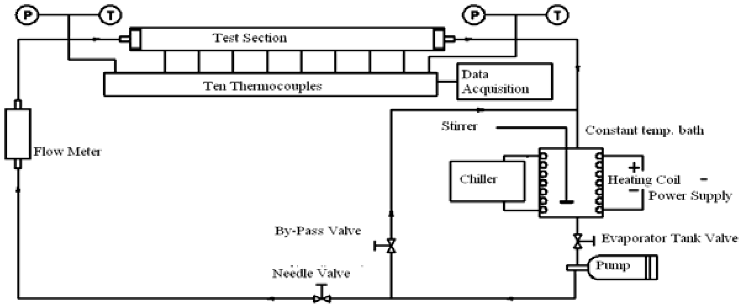
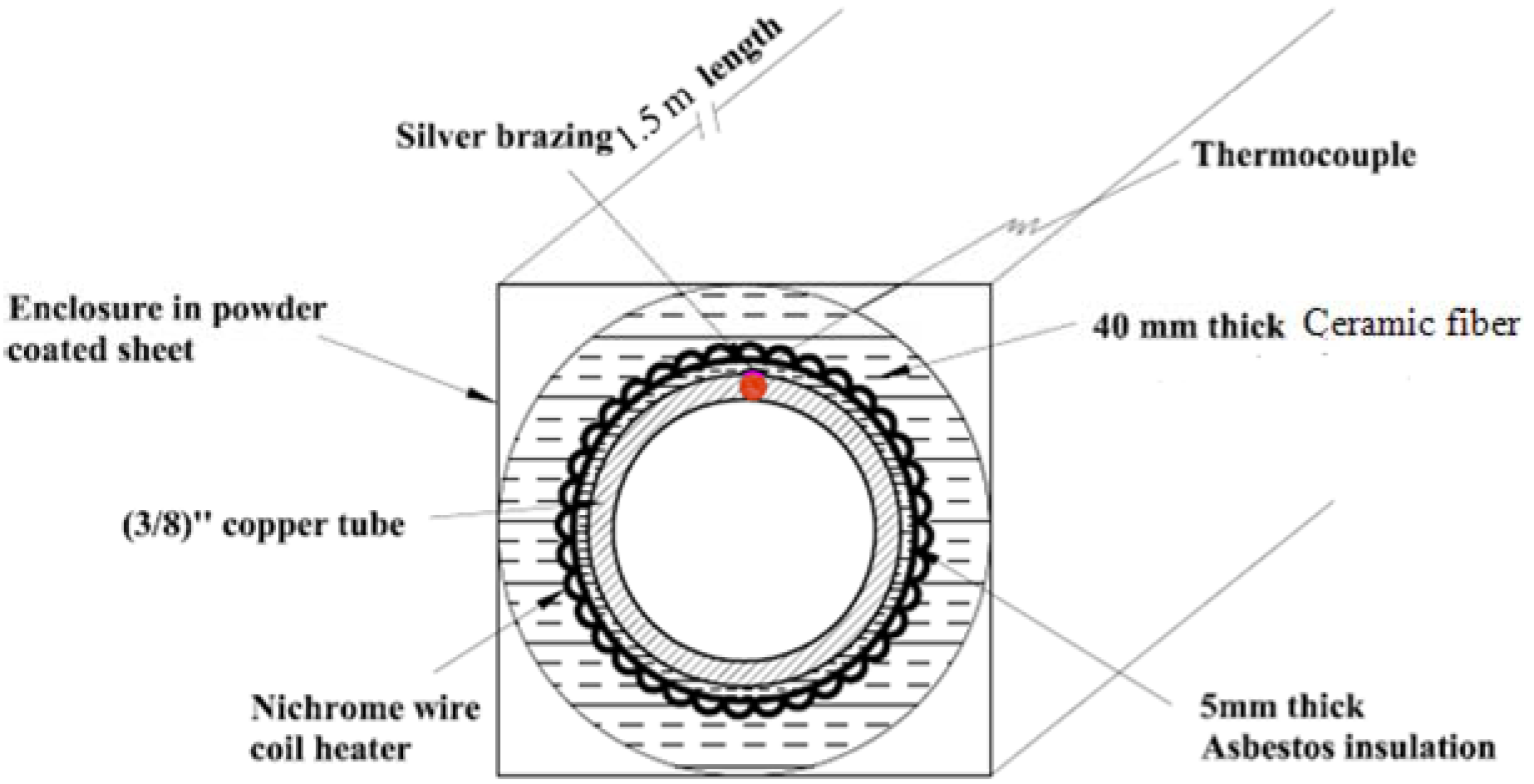
2.2. Cross sectional view of test section

Figure 2 shows the cross sectional view of the copper tube test section. A number of parameters have been considered in order to maintain a constant heat flux across the test section. The temperatures at different nodes are determined by the thermocouple reading. Using this, the temperature of the fluid medium is calculated. The variation in the temperature indicates the heat transfer characteristics of the fluid medium. Hence, enough care has been taken to ensure that the temperature indicated by the thermocouple is the true wall temperature. The thermocouple is covered with silver cement in order to avoid the effect of radiations. Asbestos (5 mm thick) is wrapped around the copper tube as insulation to prevent it from conducting the given heat load. Once, the insulation is wrapped around the tube, a nichrome wire coil-heater is wound on it. A 40 mm thick fiber glass-wool insulation encloses the coil set up to prevent the heat loss. The entire arrangement is placed in the enclosure made of a powder coated sheet which is of 1.5 m in length.
Figure 2. Cross sectional view of the test section.
Energies 02 00097 g002

2.3. Experimental procedure

Experiments were performed for mass flow rates ranging from 0.0113 kg/s to 0.0139 kg/s and inlet temperatures at 10°C and 17°C and Reynolds number from 1,350 to 2,170. During the experimental runs, the tube outer wall temperatures, inlet and outlet temperatures of the nanofluid, mass flow rates and electric power inputs as well the static pressures are measured. The inner wall temperatures are measured by applying the 1-D heat conduction equation in radial direction. The bulk fluid temperature along the axial distance in the test section is obtained through the energy balance between the point where the heat transfer coefficient is to be obtained and the entrance of the test section. From the measured values of temperatures the local convective heat transfer coefficient and the Nusselt number of nanofluids at a given flow condition are determined. The same procedure is repeated for different, heat flux and inlet temperatures and at different operating conditions. The test conditions and detailed procedure to calculate the Nusselt number of nanofluids are given in Table 2 and Figure 3.
Table 2. Test conditions and parameters.
ParametersTest Conditions
Base fluidWater
Particle MaterialCuO
Particle size40 nm
Volume fraction0.003% by vol.
Flow RegimeLaminar Re = 1,350 – 2,170
Heat load300 – 400 watts
Inlet temperature10 – 17 0C
Figure 3. Flow chart calculation of Nusselt number of nanofluids.
Energies 02 00097 g003

2.4. Nanofluid preparation

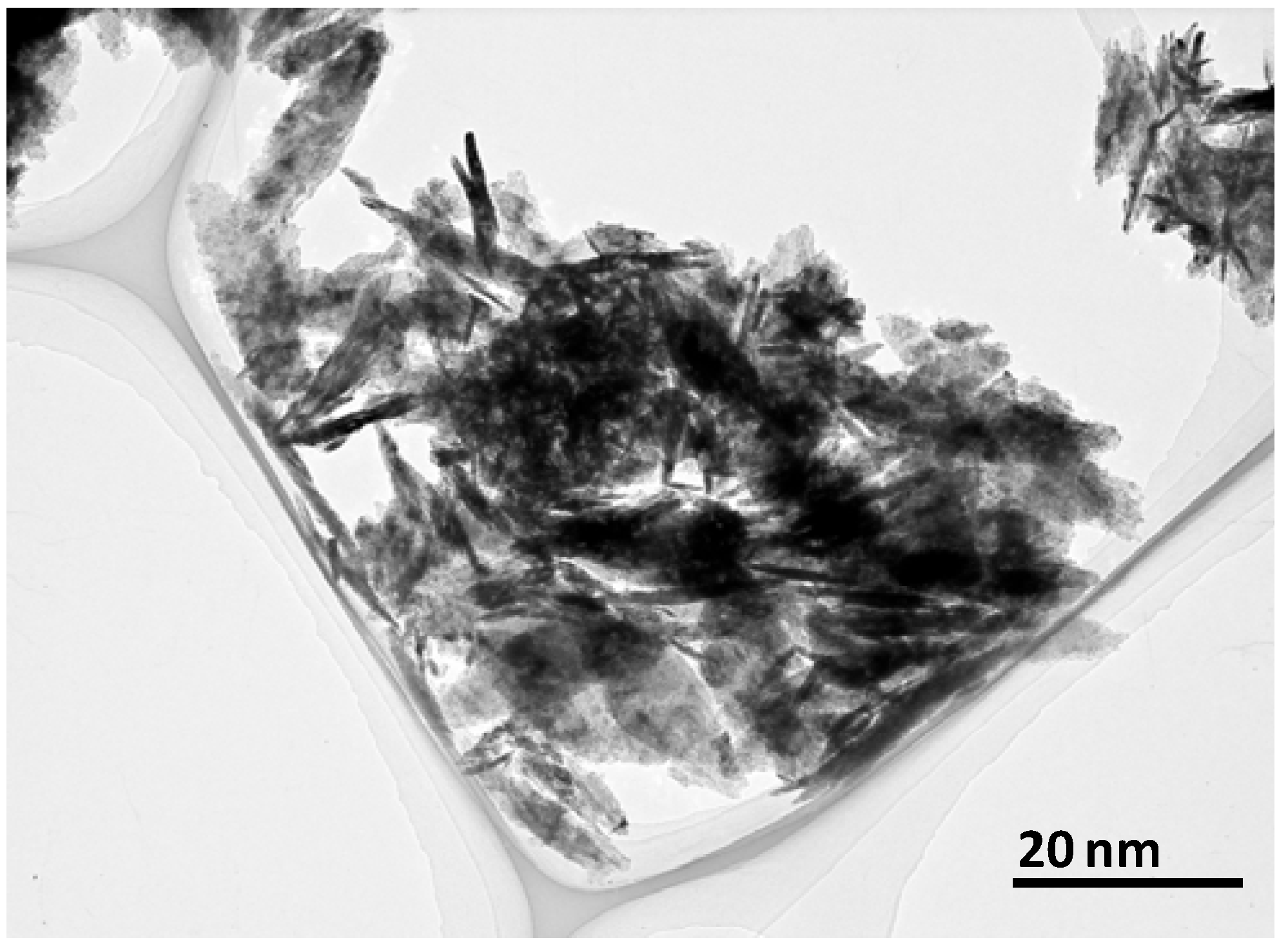
2.4.1. Materials and dispersion of nano-particles in base fluid

Nanofluid preparation is important when using the nanofluid as a working fluid. In order to prepare nanofluids by dispersing the nanoparticles in a base fluid, proper mixing, and stabilization of the particles is required. In this study, CuO (copper oxide) nano-particles were used. Average crystallite size of this CuO sample was estimated from peak broadening of the most intense X-ray diffraction (XRD) peak after eliminating instrumental and strain broadening is 10 nm. Microstructure of the sample using TEM was recorded by using a Philips CM12 transmission electron microscope. To do TEM measurements the sample was prepared by placing a drop of nanocrystal dispersion in ethanol on a carbon coated Cu grid, kept at room temperature to evaporate the ethanol. The shape is rod-like as shown in TEM image in Figure 4. Then the nano-particles were poured into the base fluid, particles sedimented within several minutes because the particles remain within the clusters without being dispersed. To disperse particles sonication was used with an ultrasonic vibrator to disperse the nanoparticles into the base water. Following this, the nanofluids were sonicated continuously for 2–7 h using an ultrasonic vibrator in order to ensure complete dispersion. After this the prepared nanofluid is used in the experimental test loop for taking the readings.
Figure 4. TEM image of CuO particles. Before dispersed in liquid, particles are strongly aggregated.
Energies 02 00097 g004

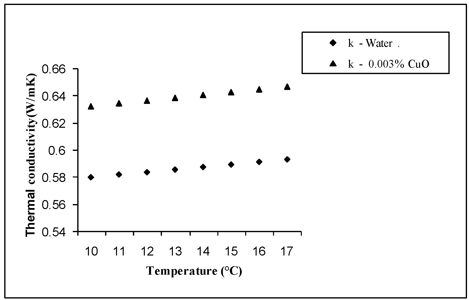
2.5. Nanofluid properties

The transport properties such as density, specific heat, heat capacity, viscosity, and thermal conductivity of nanofluids are the main properties that entail in the convective heat transfer of nanofluids [33]. It should be noted that these transport properties are functions of temperature. As a consequence, the properties were calculated by using the mean fluid temperature between the inlet and outlet, while the thermal conductivity was measured with predicted models at 10°C and 17°C.
Density: The effective density of the nanofluid containing suspended particles can be evaluated by the following equation:
ρ n f = ( 1 φ ) ρ + b f φ ρ p
The above equation has been experimentally validated by Pak and Cho [15] for use with nanofluids.
Specific heat: Xuan and Roetzel [34] proposed the equation for calculating the specific heat of nanofluids based on the heat capacity concept:
( ρ C p ) n f = ( 1 φ ) ( ρ C p ) b f + φ ( ρ C p ) p
Dynamic viscosity: The effective dynamic viscosity of nanofluids can be calculated using Einstein’s equation for a viscous fluid containing a dilute suspension ( φ ≤ 2%) of small, rigid, spherical particles (Drew and Passman [35]). As very dilute suspensions were used in this work the Einstein equation was used to estimate the viscosity of nanofluids. Wen and Ding [19] also used the same equation for calculating the viscosity.
μ = μ 0 ( 1 + 2.5 φ )

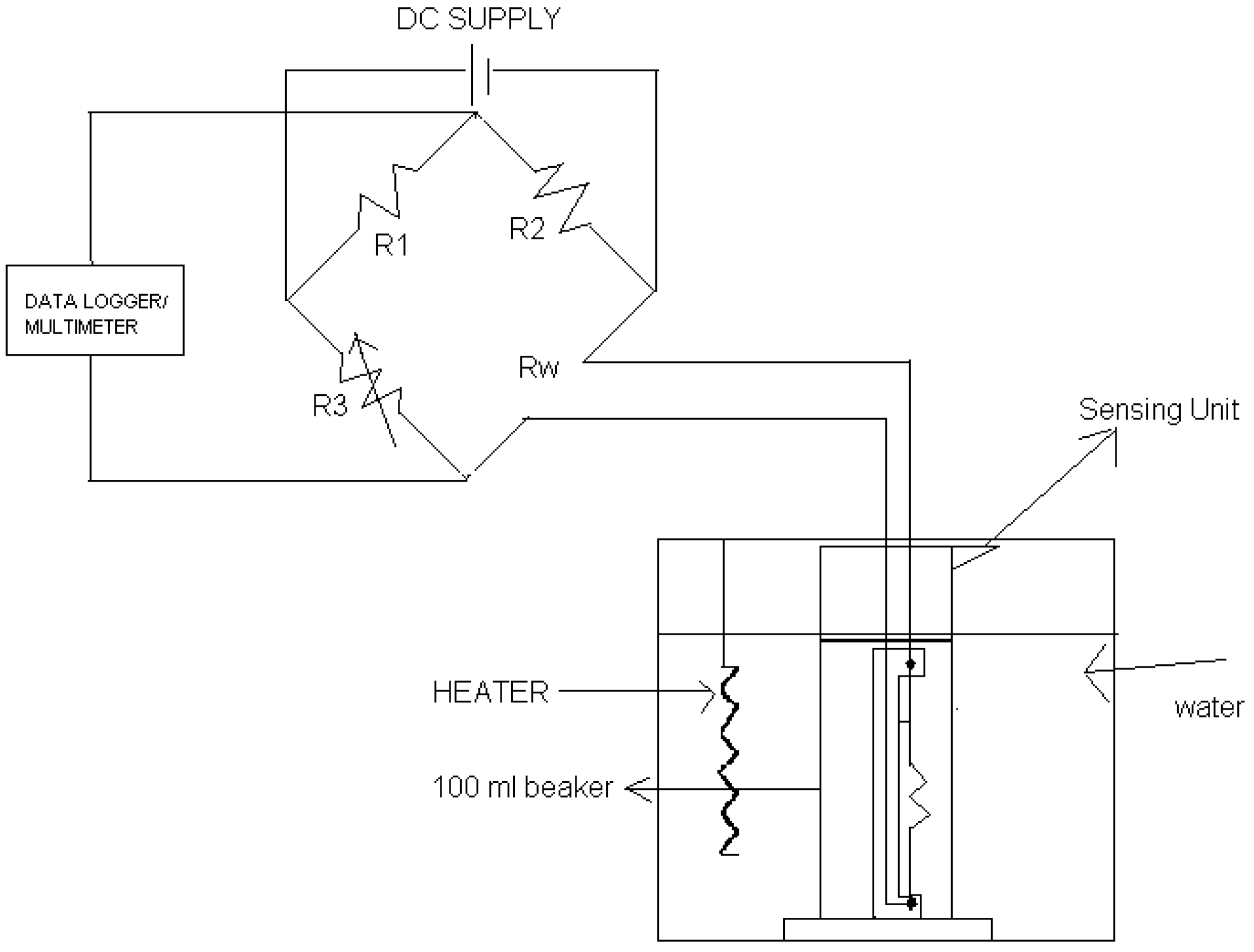
2.6. Transient Hot Wire Method

The transient hot-wire (THW) technique is the most used method to measure the thermal conductivity of fluids. A hot wire system involves a wire suspended symmetrically in a liquid in a vertical cylindrical container. The wire serves both as heating element and as thermometer. This method is based on applying a constant current to a thin wire, usually made of platinum and measuring the time evolution of its electrical resistance due to the temperature increase. The thermal conductivity of the liquid is determined by observing the rate at which the temperature of a very thin platinum wire increases with time after a step change in voltage has been applied to it, thus creating a line source of constant heat flux per unit length. Normally, Platinum wire is used as hot wire because its resistance temperature relationship is well known over a wide range of temperatures.

2.6.1. Experimental setup

The experimental setup for measuring the thermal conductivity of nanofluids by the transient hot-wire method is shown in Figure 5. A wire is placed along the axis of the cell, which is surrounded by the liquid whose thermal conductivity is to be measured. The wire is used for both heating and for temperature sensing. The hot wire is used as a line heat source, so the diameter and length of the wire used for measuring the thermal conductivity is 75 µm and 15 cm. The length of the wire is kept to 15 cm, which compared to the wire diameter represents an infinitely long line heat source, assuring one directional (radial) heat transfer. The whole circuit is connected to Wheatstone bridge.
Figure 5. Schematic Diagram of the Experimental setup for Thermal Conductivity Measurement.
Energies 02 00097 g005
Initially the bridge is balanced by adjusting the variable resistor R3. That is, there should not be potential drop between the two arms which is connected to the multi-meter. In the Wheatstone bridge, Rw is the resistance of hot wire, R1 is a one kilo-ohm variable resistor, R2 is a 1 kΩ fixed resistor and R3 is a 15 Ω fixed resistor. Then the voltage is applied to the circuit, the platinum wire heated up because it is too thin, this rise in temperature increased the resistance of the wire, which in turn caused an emf that is observed in the millimeter. The voltage drop across the bridge is measured. The change in resistance is found using the given formula:
Δ R w = ( R w * R 3 ) 2 * Δ V V * R 3
where,
R w = R o ( 1 + α T )
From the above equation the temperature of the wire is found and by finding the slope of the graph between temperature verses log of time the thermal conductivity of the fluid is found by using the formula:
k = q 4 π ( T 2 T 1 ) ln ( t 1 / t 2 )
where,
q = I w 2 * R w l
It is a well known fact that the transport properties are the functions of temperature [36]. Hence the viscosity is calculated by the mean fluid temperature between the inlet and outlet of the test section. The thermal conductivity is calculated at different temperatures.
Figure 6 shows that CuO nanofluids with low concentrations of nanoparticles have considerably higher thermal conductivities than water. The thermal conductivity ratio improvement for CuO nanofluids is approximately linear with the temperature. For CuO nanoparticles at a volume fraction of 0.003%vol the thermal conductivity was enhanced by up to 8.3 %. Thermal conductivity enhanced by 22% at a volume fraction of 0.04 (4 vol.-%) has been reported for CuO-ethylene glycol suspensions [4]. Furthermore, a maximum increase in thermal conductivity of 17% is observed for 0.4 vol.-% CuO nanoparticles dispersed in deionized water [39]. All the experimental results show that the addition of CuO nanoparticles to a base fluid leads to dramatic enhancement of thermal conductivity. CuO nanofluids thus have good potential for effective heat transfer applications.
Figure 6. Thermal Condutivity of CuO/Water Nanofluid.
Energies 02 00097 g006

2.7. Reliability and accuracy of the experimental system

The initial test for reliability and accuracy of the experimental system with de-ionized water as the working fluid was conducted before conducting the experiments on nanofluids. The experimental results were compared with the familiar correlation for internal flow in short tubes, thermally developing and hydro dynamically fully developed ( R e P r D x ) > 10 and Pr > 0.6, laminar flow inside tubes and uniform wall heat flux boundary condition [37]:
N u = 1.30 ( R e P r D x ) 0.333
Figure 7. Comparison of experimental values of water with Eq. 5 along axial direction.
Energies 02 00097 g007
Figure 7 shows the comparison between the correlation and the experimental values using de-ionized water for the Reynolds number 1,570 and 400 W heat load with inlet temperature 170C. A good agreement with less than 4% is seen between the equation and the measured values with de-ionized water which confirmed the validity of the experimental setup.

3. Mathematical Modeling

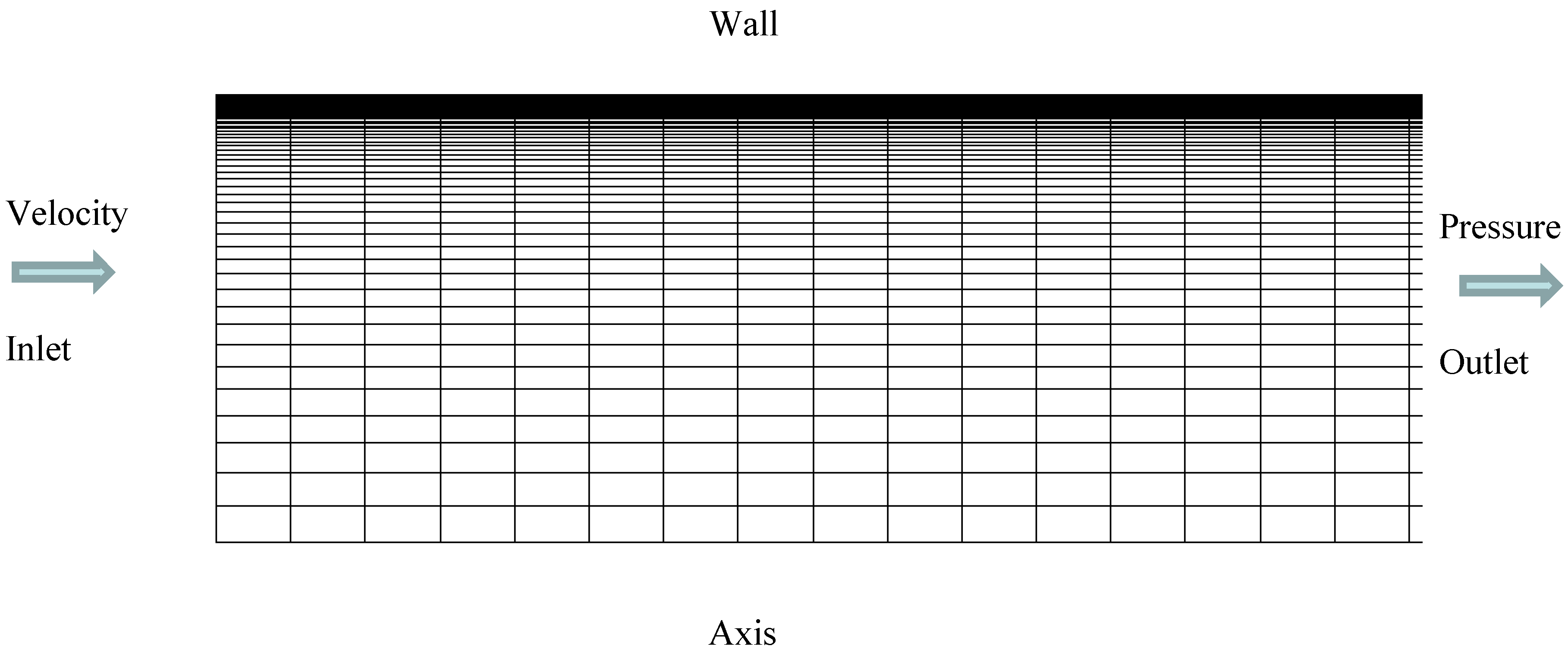
3.1. Geometrical Configurations

In order to compare the results with the experiments, similar configurations like the geometry of the tube and the concentration of the copper oxide nanoparticles were considered. The length of the tube is long enough for the fully developed condition to prevail.
Figure 8. Geometrical Configuration 2-D Axisymmetric about X – axis.
Energies 02 00097 g008

3.2. Assumptions

As it is comparatively easy to fluidize the nanoparticles in the base fluid, the effective mixture could be assumed to behave like a single phase fluid. A local thermal equilibrium with zero relative velocity is also assumed between the fluid phase and the nanoparticles as the nanoparticles are very small in size. The effective thermophysical properties are assumed to be dependent on the temperature and concentration of the nanoparticles. Further, the nanofluids are assumed to be incompressible with constant physical properties. The compression work and the viscous dissipation are assumed negligible in the energy equation. Under these assumptions, the classical theory of single phase fluid can be applied to nanofluids.
Conservation of mass:
div (ρV) = 0
Conservation of momentum:
div (ρVV) = - grad P + μ ∇2V
Conservation of energy:
div (ρVCpT) = div (kgradT)
In the above equations, V, P and T are respectively fluid velocity vector, pressure and temperature; all fluid properties are evaluated at the reference temperature that is the fluid inlet temperature T0.

3.3. Boundary Conditions:

The governing equations of the fluid flow are non-linear and coupled partial differential equations, subjected to the following boundary conditions. Uniform axial velocity Vin, and temperature Tin prevail at the tube inlet section, while fully developed conditions prevail at the outlet section. One half of the tube was only modeled due to symmetry. The condition of uniform heat flux prevails at the wall. Axis condition was applied on the lower wall of the domain.

4. Numerical Methods

The systems of governing equations (9) – (11) were solved by the control volume approach using the Fluent computational fluid dynamics code. The control volume approach converts the governing equations to a set of algebraic equations that can be solved numerically. It employs the conservation statements given by the respective governing equations over finite control volumes. For higher accuracy second order unwinding scheme for convection terms and central difference for diffusive term was utilized. Staggered grid schemes are used to evaluate the velocity components at the center of control volume interfaces and all scalar quantities such as pressure and temperature are calculated in the center of control volume. The conservation equations of mass, momentum and energy were solved iteratively using the segregated solver and a pressure correction equation was used to ensure the conservation of momentum and mass. A SIMPLE scheme was adopted for the treatment of pressure. The Reynolds number studied in this work is low, laminar viscous model was employed. Double precision calculation was used as the geometry had a large aspect ratio. During the iterative process, the residuals were carefully monitored. For all simulations performed in this work, converged solutions were considered for residuals lower than 10−6 for all the governing equations.

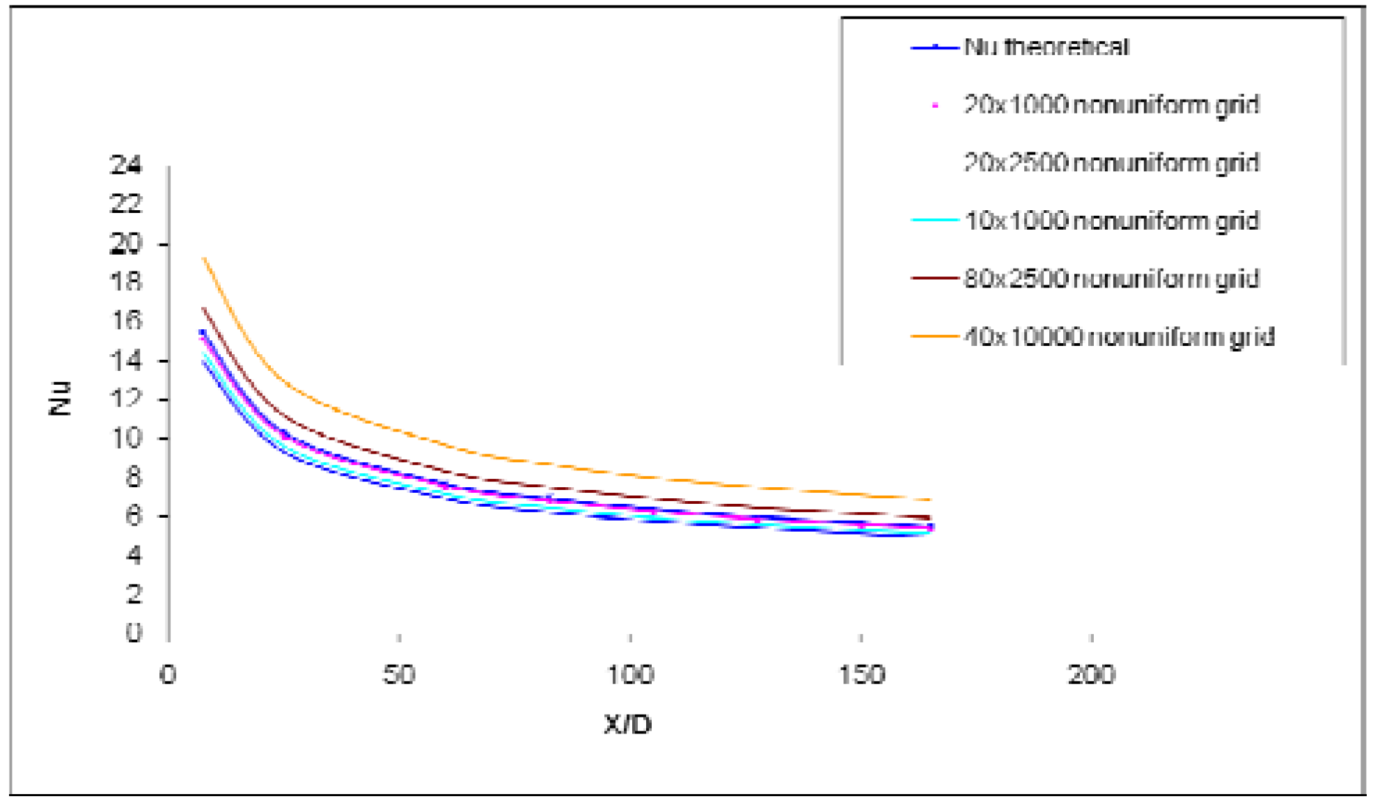
4.1. Grid Optimization and Code Validation

A number of non – uniform grids were tested in order to obtain an accurate and consistent result both with flow and heat transfer. The grid used in the present analysis was (20 x 1000), 20 in the radial and 1000 in the axial direction.
In order to establish grid independence several numerical experiments were carried out with radial nodes varying from 20, 40, 80 with high refinement at the walls and axial nodes varying from 1,000, 2,500, 10,000 with the refinement at the entrance using water as working fluid. In order to validate the computational model, the results were compared with the theoretical data available for the conventional fluid namely water which is given in Equation 8. As shown in Figure 9. It was observed that 20 x 1,000 grid showed good agreement with the theoretical results and hence this model was considered as the optimum grid for carrying out all the analysis.
Figure 9. Local variation of Nusselt number for water with a standard numerical result.
Energies 02 00097 g009

5. Experimental Results and Discussion

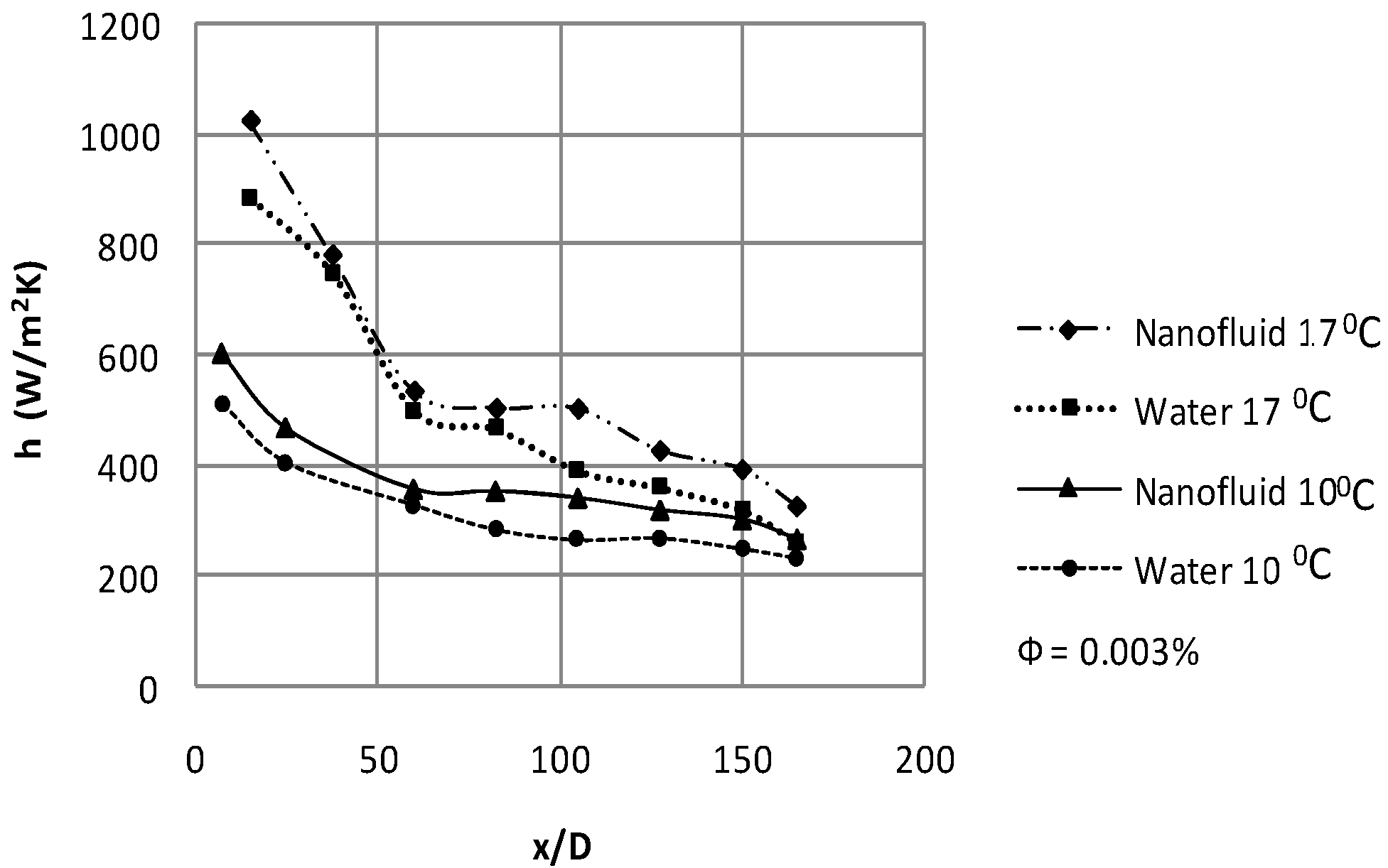
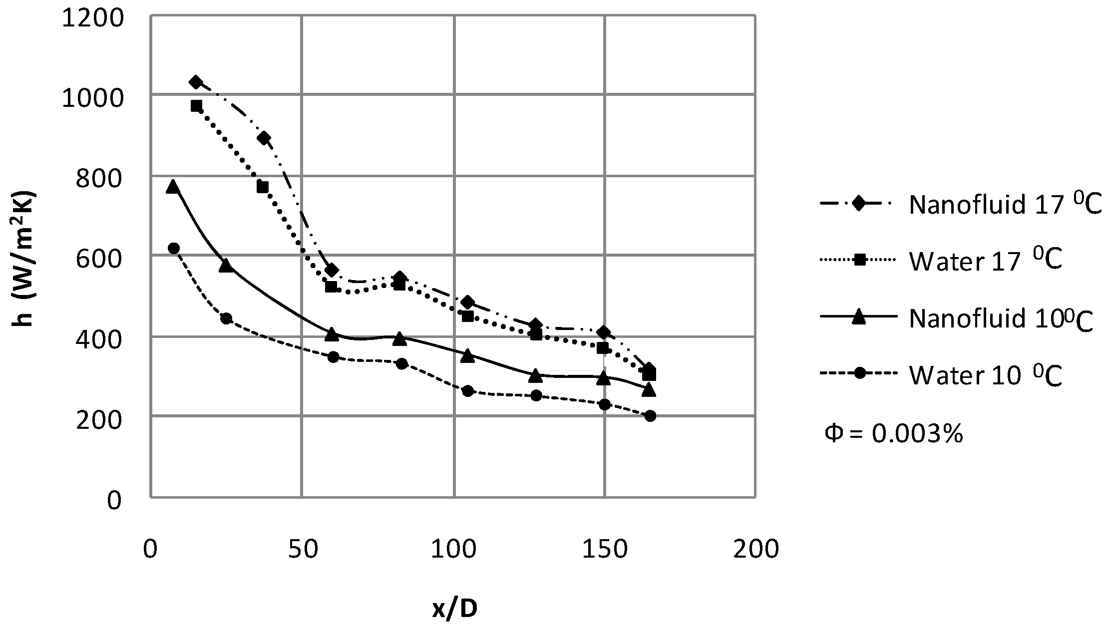
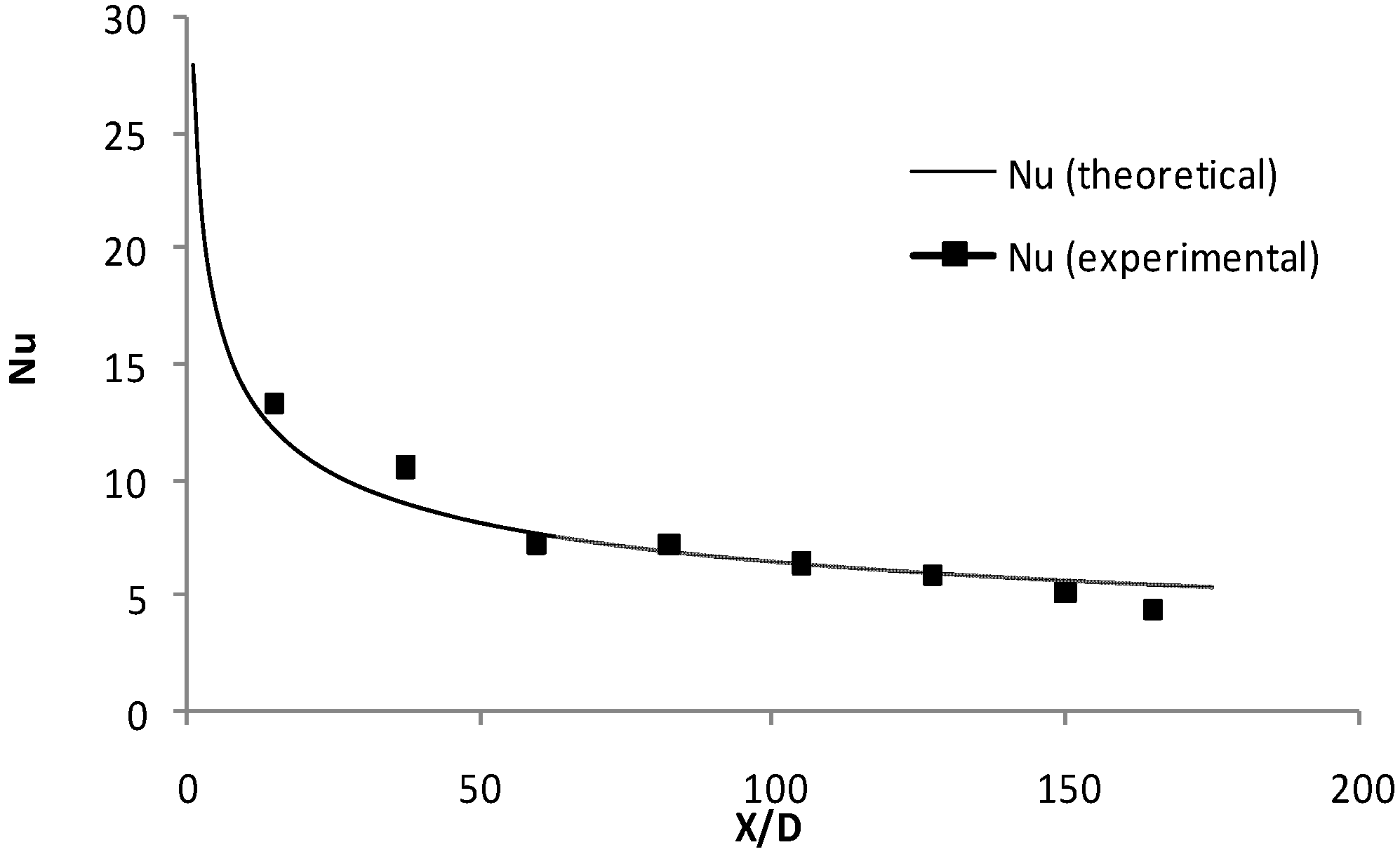
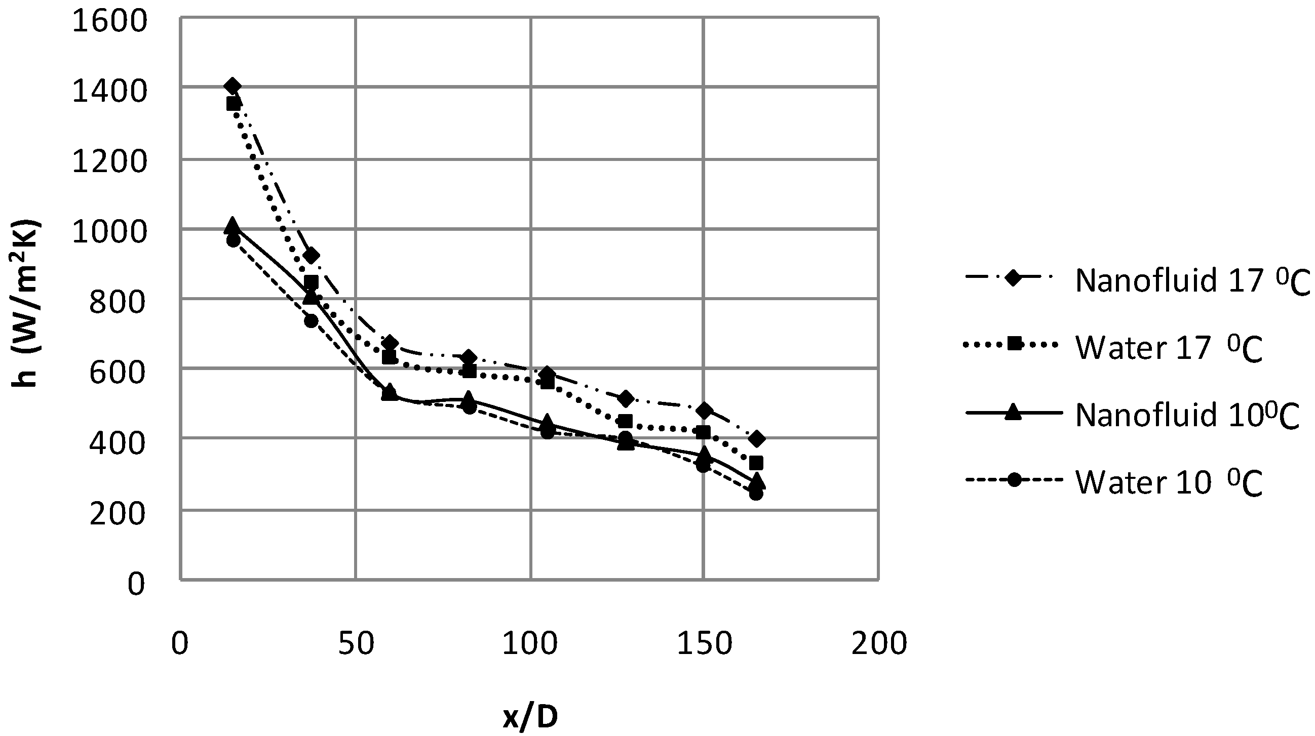
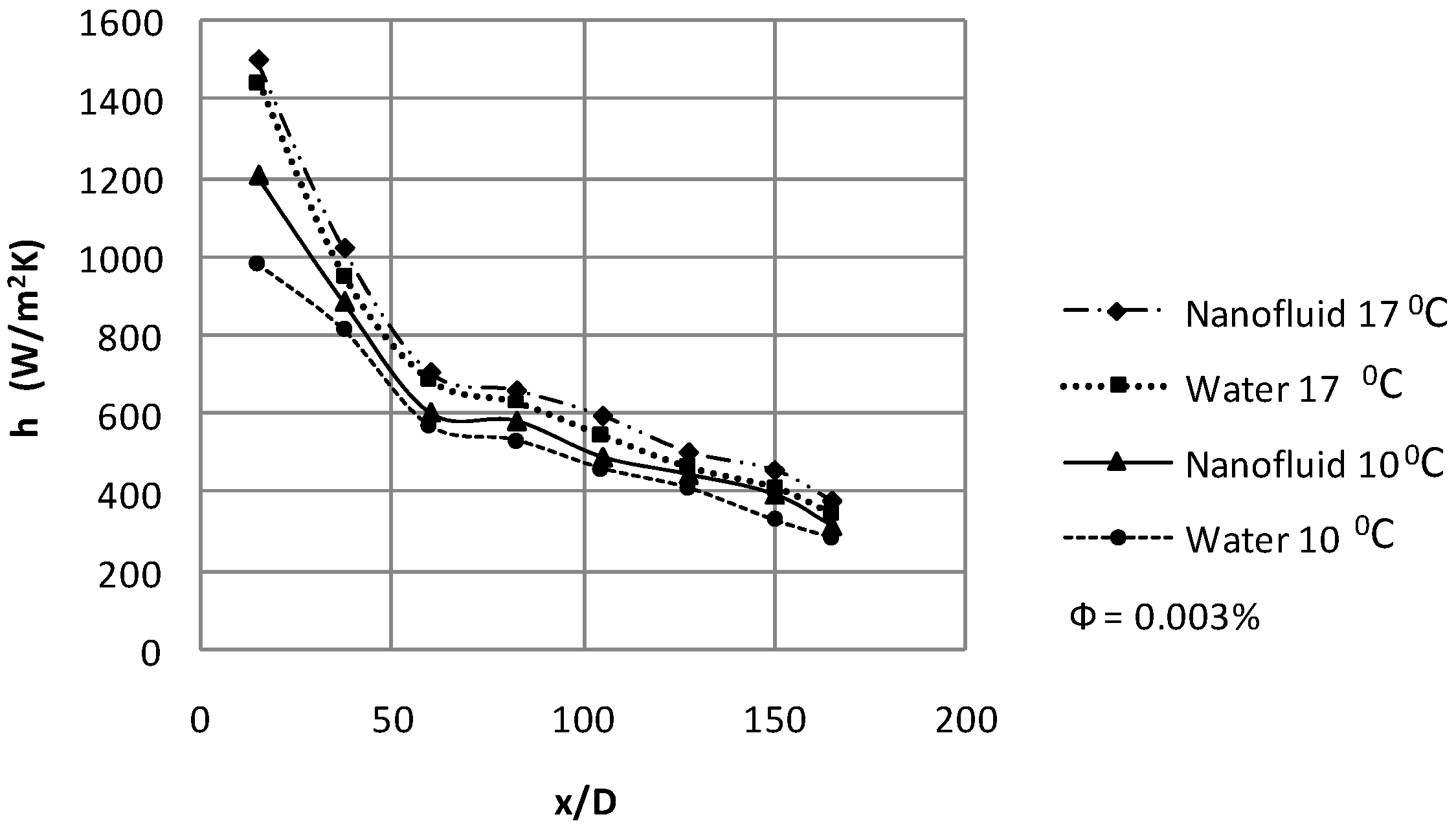
5.1 Axial profiles of convective heat transfer coefficient

Figure 10, Figure 11, Figure 12 and Figure 13 show the variation of local convective heat transfer coefficient along the axial distance from the entrance of the test section at two Reynolds numbers, two different temperatures and two heat fluxes. The results clearly show that even the use of very low volume fraction (0.003%) of nanofluids considerably enhances the convective heat transfer, particularly at the entrance region and at higher Reynolds number. Likewise, the improvement in convective heat transfer is also observed at higher temperature and at high heat flux.
Figure 10. Axial profile of local heat transfer coefficient for Re = 1,350 and q” = 7,960 W/m2.
Energies 02 00097 g010
Figure 11. Axial profile of local heat transfer coefficient for Re = 1,700 and q” = 7960 W/m2.
Energies 02 00097 g011
Figure 12. Axial profile of local heat transfer coefficient for Re = 1350 and q” = 10610 W/m2.
Energies 02 00097 g012
Figure 13. Axial profile of local heat transfer coefficient for Re = 1700 and q” = 10610 W/m2.
Energies 02 00097 g013
From Figure 10, Figure 11, Figure 12 and Figure 13, it is noted that for nanofluids containing 0.003% nanoparticles by volume, the local heat transfer coefficient at Position 3 (x = 0.48 m, x/D = 60) is, respectively, 7.5% and 14.1% higher at Re = 1,350 and 1,700 in comparison with water for 7,960 W/m2 and inlet temperature of 10°C. For nanofluids containing 0.003% nanoparticles by volume, the local heat transfer coefficient at Position 3 (x = 0.48 m, x/D = 60) is, respectively, 6.2% and 6.7% higher at Re = 1,350 and 1,700 in comparison with water for 7,960 W/m2 and inlet temperature of 17°C. For nanofluids containing 0.003% nanoparticles by volume, the local heat transfer coefficient at position 2 (x = 0.2 m, x/D = 25) is, respectively, 8% and 8.2% higher at Re = 1,350 and 1,700 in comparison with water for 10,610 W/m2 and inlet temperature of 10°C. For nanofluids containing 0.003% nanoparticles by volume, the local heat transfer coefficient at Position 2 (x = 0.2 m, x/D = 25) is, respectively, 7.1% and 8.5% higher at Re = 1,350 and 1,700 in comparison with water for 10,610 W/m2 and inlet temperature of 17°C. These Figures also show that for the same Reynolds number the heat transfer coefficient is found to be high for higher inlet temperature and high heat flux. The heat transfer enhancement reaches the constant value with increasing distance from the entrance region as the flow becomes fully developed.
Figure 14. Axial profile of local heat transfer coefficient at 10,610W/m2 at 10°C for Re = 1,350
Energies 02 00097 g014
Figure 14 shows this variation for a Reynolds number of 1,350 at 10ºC for a heat flux of 10,610W/m2 between the numerical and experimental results. It can be seen that at the entrance region there was an enhancement in the heat transfer under the combined effect due to nanoparticles and boundary layer development. An enhancement of around 11% was observed at the entrance region for the nanofluid while compared to water, heat transfer augmentation of nearly 7 % is achieved at the tube end while compared to the base fluid at same Reynolds number. The experimental and numerical results were found to be in good agreement. Further validation at a higher Reynolds number of 1,600 for the same temperature and heat flux is made as shown in the Figure 15.
Figure 15. Axial profile of local heat transfer coefficient at 10,610W/m2 at 10°C for Re = 1,600
Energies 02 00097 g015

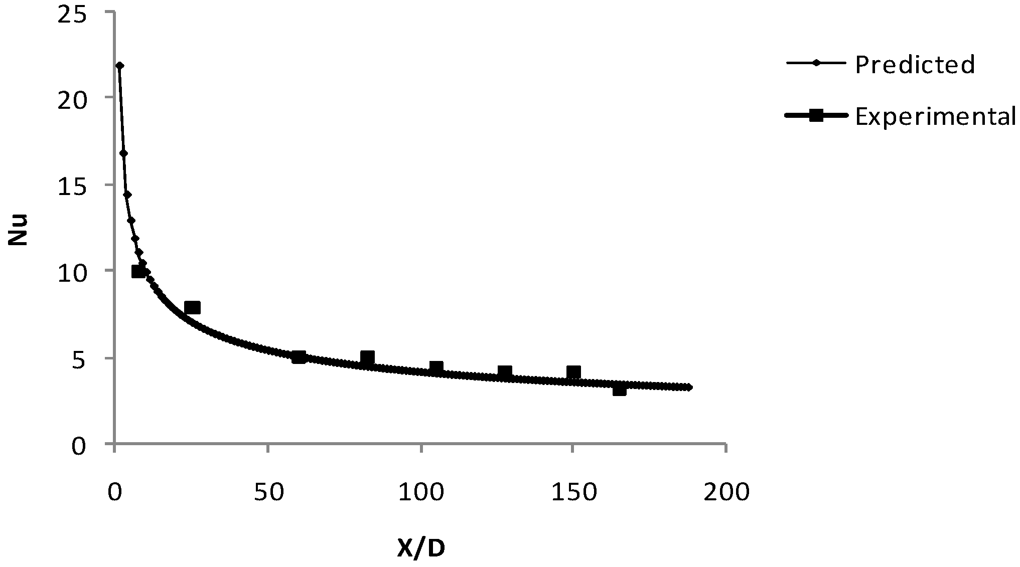
6. Correlations for Nusselt Number (Nu)
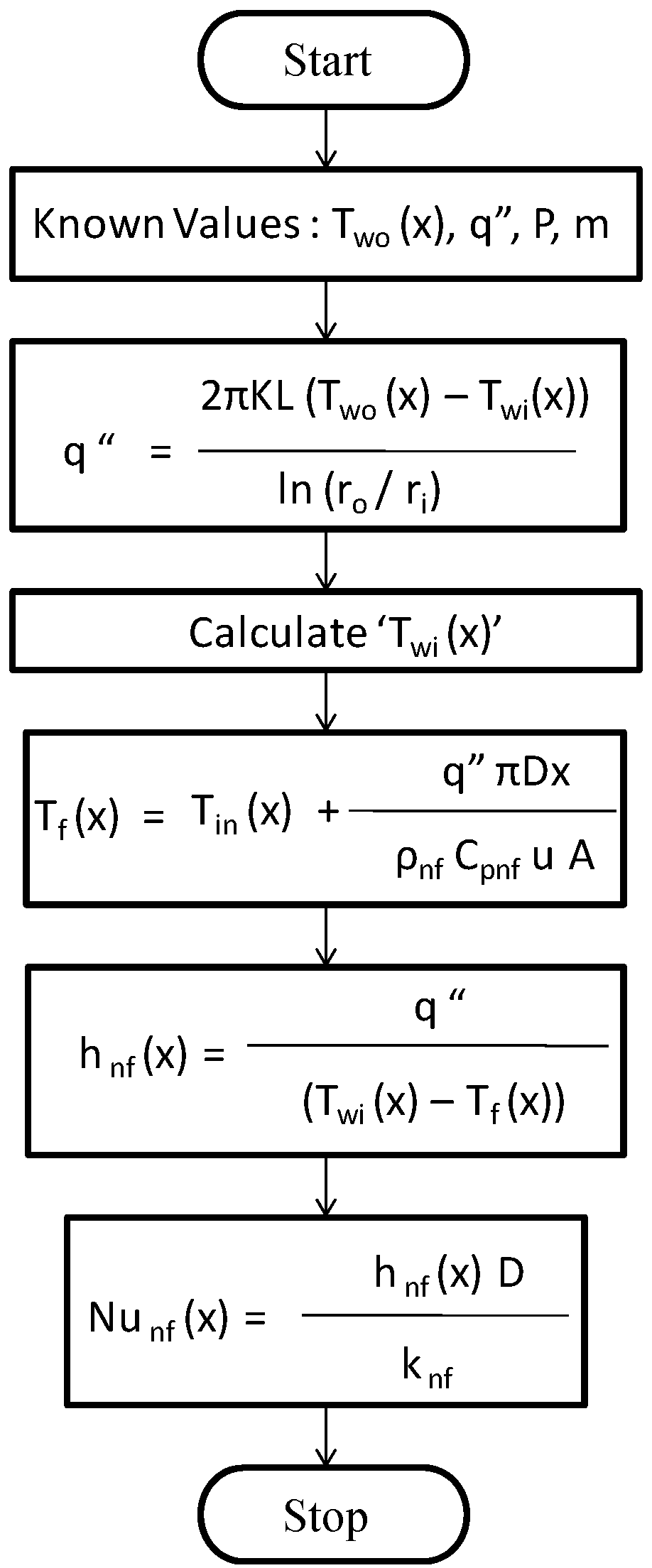
The nanofluid behaves more like a fluid than the conventional solid-fluid mixtures in which relatively larger particles with micrometer or millimeter size are suspended. But the nanofluid is a two-phase fluid in nature and has some common features of the solid-fluid mixtures. It is known that the heat transfer coefficient (Nusselt number) of the nanofluid depends on various factors such as thermal conductivity, heat capacity of both the base fluid and the nanoparticles, viscosity of the nanofluid, the volume fraction of the suspended particles, the dimensions and the shape of the particles. Therefore, in general, the Nusselt number of nanofluid can be expressed as follows:
N u n f = f ( Re , Pr , k n f k 0 , ( ρ C p ) n f ( ρ C p ) 0 , φ , d i m e n s i o n s     a n d   s h a p e   o f   p a r t i c l e s )
The correlations developed so far give either the average Nusselt number or Nusselt number in the fully developed region [28,30]. It is usually a function of Reynolds number and Prandtl number. However, the variation of Nu along the axial distance and diameter of the tube has not been reported so far for nanofluids. Hence, from the available experimental data a new correlation has been evolved for determining the local Nusselt number as a function of Re, Pr (transport property) and D x (axial distance) based on the experiments carried out for the laminar regime under constant heat flux condition for low particle concentration (0.003%) by vloume.

6.1. Methodology

A multi variable linear regression analysis is carried out to evolve the correlation. As, already stated, the correlation evolved for determining the local Nusselt number is taken as a function of Re, Pr and D/x which is given in Equation 12:
N u ( x ) = C   Re a   Pr b ( D x ) k
where, C, a, b, and k are the constants to be determined. The equation is converted into a logarithmic form as given in Equation 13:
ln   N u ( x ) =   ln C + a ln Re + b ln Pr + k ln ( D x )
P = Q + a A + b B = k F
where,
P = ln N u ( x ) ,     Q = ln C ,     A = ln Re ,     B = ln Pr ,     a n d     F = ln ( D X )
The experimental values of all parameters namely Nu (x), Re, Pr and (D/X) are converted into logarithmic values and are substituted in the deviation equation:
E = [ P 1 + Q a   A 1 b   B 1 k   F 1 ] 2 + [ P 2 + Q a   A 2 b   B 2 k   F 2 ] 2 + [ P 3 + Q a   A 3 b   B 3 k   F 3 ] 2 +   [ P 4 + Q a   A 4 b   B 4 k   F 4 ] 2 + ............. + [ P n + Q a   A n b   B n k   F n ] 2
The constants Q, a, b, k are determined by differentiating the above equation partially with respect to the respective constants:
E Q = 0 ,    E a = 0 ,    E b = 0 ,    E k = 0 ,
Then, the constants are substituted in Equation 12 and the new correlation for calculating the Nu(x) is determined and given in Equation 17:
N u = 0.155   R e 0.59 P r 0.35 ( D / x ) 0.38
Figure 16. (a) Nusselt number variation with axial distance at 10610 W/m2 at 10°C for Re = 1350.
Energies 02 00097 g016aEnergies 02 00097 g016b
(b) Nusselt number variation with axial distance at 10610 W/m2 at 10°C for Re = 1700.
Figure 16 (a) and (b) show the curves of the theoretical predictions of convective heat transfer coefficients of nanofluid from the developed correlation (17). The variation of the local Nusselt number along the axial distance of the tube at 10°C entry temperature for both the experiments and correlation are given in the graph. There exists good agreement between the results calculated from this correlation and the experimental values. Hence this correlation can be used to predict the axial variation in the local heat transfer coefficient of nanofluid. From Figure 17 it can be seen that the predicted Nusselt number falls within ±10% deviation when compared with experimental results. The correlation is valid for the entire laminar flow regime of ≤ Re = 2,300 and φ = 0.003%.
Figure 17. Experimental and predicted Nusselt numbers of CuO nanofluids.
Energies 02 00097 g017

7. Discussion on the possible mechanisms for enhancement

7.1. Effect of low volume fraction of CuO nanofluid on the convective heat transfer

Figure 10, Figure 11, Figure 12 and Figure 13 show the enhancement of convective heat transfer coefficient, with reference to the de-ionized water as a function of axial distance even at the low volume fraction (0.003%) of CuO nanofluid. This clearly proves that the presence of nanoparticles in the base fluid increases the convective heat transfer coefficient, and the increase is clearly seen even though the concentration is less. At a given concentration the enhancement of heat transfer coefficient increases with x/D initially, particularly in the entrance region and decreases with the axial distance and almost reaches a constant value as the flow becomes fully developed. There are two possible reasons for the enhancement. 1). the suspended particles increase the thermal conductivity of the two-phase mixture; 2). the chaotic movement (Brownian movement) of ultrafine particles which accelerates the energy exchange process in the fluid. It is also observed that the increase in the measured heat transfer coefficient is because of the nanofluid thermo-physical properties and this has resulted in an increase in heat transfer rate.

7.2. Effect of inlet temperature on the convective heat transfer

The contact between the nanoparticle and the molecules of the base fluid increases as the temperature increases which results in more energy exchange. This rise in inlet temperature influences the particle collisions in the nanofluid resulting in an enhancement of thermal conductivity. The increase in inlet temperature is directly proportional to the heat transfer enhancement. The increase in the convective heat transfer coefficient is found for a small temperature lift, 10°C – 17°C. Such characteristics were also reported by Eastman et al. [38] and the smart behavior is desirable to sense the hot spots and provide more rapid cooling in those areas. The increased heat transfer rate can be attributed to many possible mechanisms namely inertia, diffusiophoresis, magnus effect and thermophoresis. However the most possible one would be due to thermophoresis, as explained by Jacopo [39].

7.3. Effect of heat flux on the convective heat transfer

The role played by nanoparticles with respect to the heat flux applied is clearly an important one. At high heat fluxes, considerable fluctuations in the wall temperature readings were observed, indicative of flow oscillations because of the random motion (Brownian motion) of the particles that cause changes in the instantaneous values of local nanofluid temperature and heat transfer rate. As the heat flux increases from 7,960 W/m2 to 10,610 W/m2 the heat transfer coefficient increases for nanofluid for the inlet temperatures of 10°C and 17°C. This indicates that the heat transfer coefficient was more sensitive to both heat flux and mass flux changes with the addition of small volume fraction of nanoparticles when compared to fluid without nanoparticles. One possible explanation for this case is the contribution by the addition of nanoparticles with high thermal conductivity and increase in the random motion of these particles at higher heat fluxes.

7.4. Effect of Reynolds number on the convective heat transfer

The effect of Reynolds number clearly indicates that the heat transfer coefficient increases with increase in flow Reynolds number. Figure 18 shows the enhancement of heat transfer coefficient for of Cuo nanofluid for two Reynolds numbers, namely, Re=1,350 and Re=1,700. It can be seen that the heat transfer enhancement increases with increase in Reynolds number. For Re=1,350 the enhancement is ~101.and for Re=1,700 the enhancement is ~115 with the addition of nanoparticles, whereas the enhancement is found to be less because of low concentration of nanoparticles. The presence of nanoparticles in the base fluids affects the boundary layer development in pipe flows. For pure liquids, the boundary layer develops smoothly; and flows are hydrodynamically fully developed after x ~(0.05Re)D, and they are thermally fully developed after x ~ (0.05RePr)D. At the entrance (x/D = 0), the theoretical boundary layer thickness is zero, hence the heat transfer coefficient approaches infinity. Increase in k and/or a decrease in δt (thickness of thermal boundary layer) increase the convective heat transfer coefficient. On the other hand, since the boundary layer in laminar flow is thinner, the hydrodynamic and thermal entrance regions are long and in these regions the heat transfer coefficient is high. A considerable rise in heat transfer enhancement is seen at the entry length region and the enhancement increases with increase in Reynolds number. The important observation is that the entry length of nanofluids is longer than that of the pure base fluid. Addition of nanoparticles clearly shows the existence of a greater thermal developing length for nanofluids, which increases with increase in particle concentrations as well as the flow Reynolds number and hence enhancement in the convective heat transfer coefficient.
Figure 18. Effect of Reynolds number on convective heat transfer enhancement for T=100C and φ =0.003%.
Energies 02 00097 g018

5. Conclusions

The findings of the experimental investigation on the convective heat transfer performance of very low volume fraction (0.003 %) of CuO/water nanofluid in laminar regime through a circular tube are summarized below.
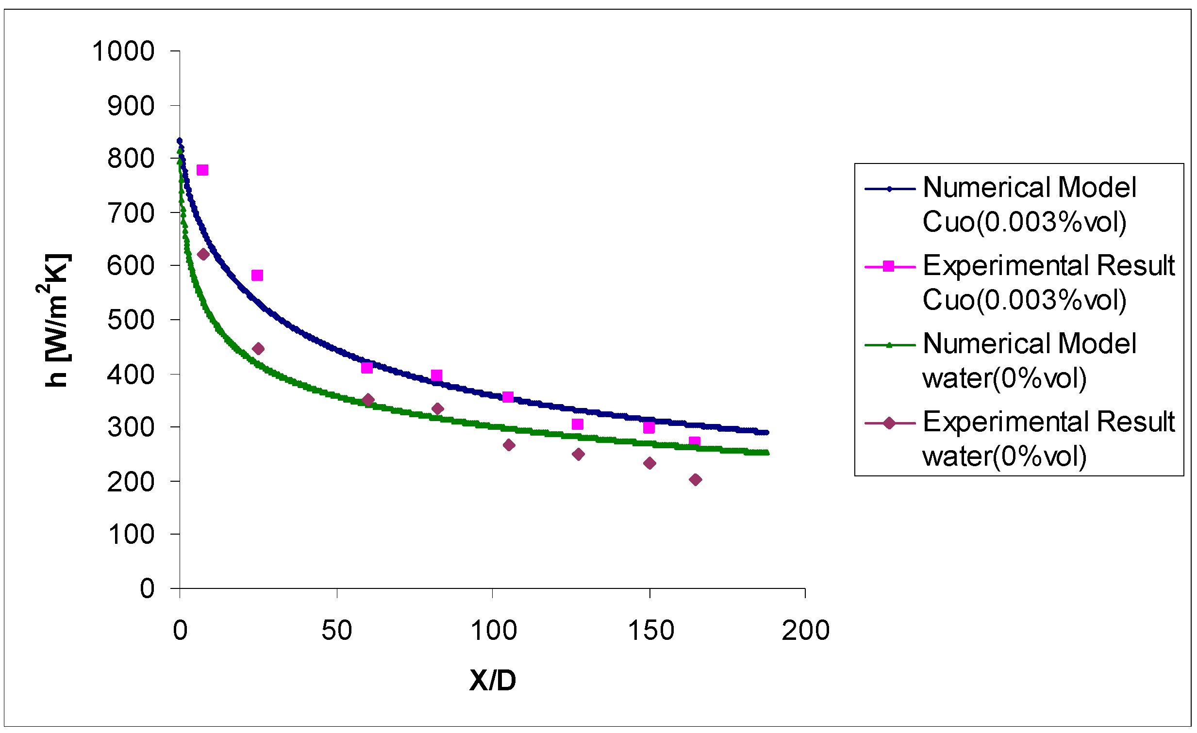
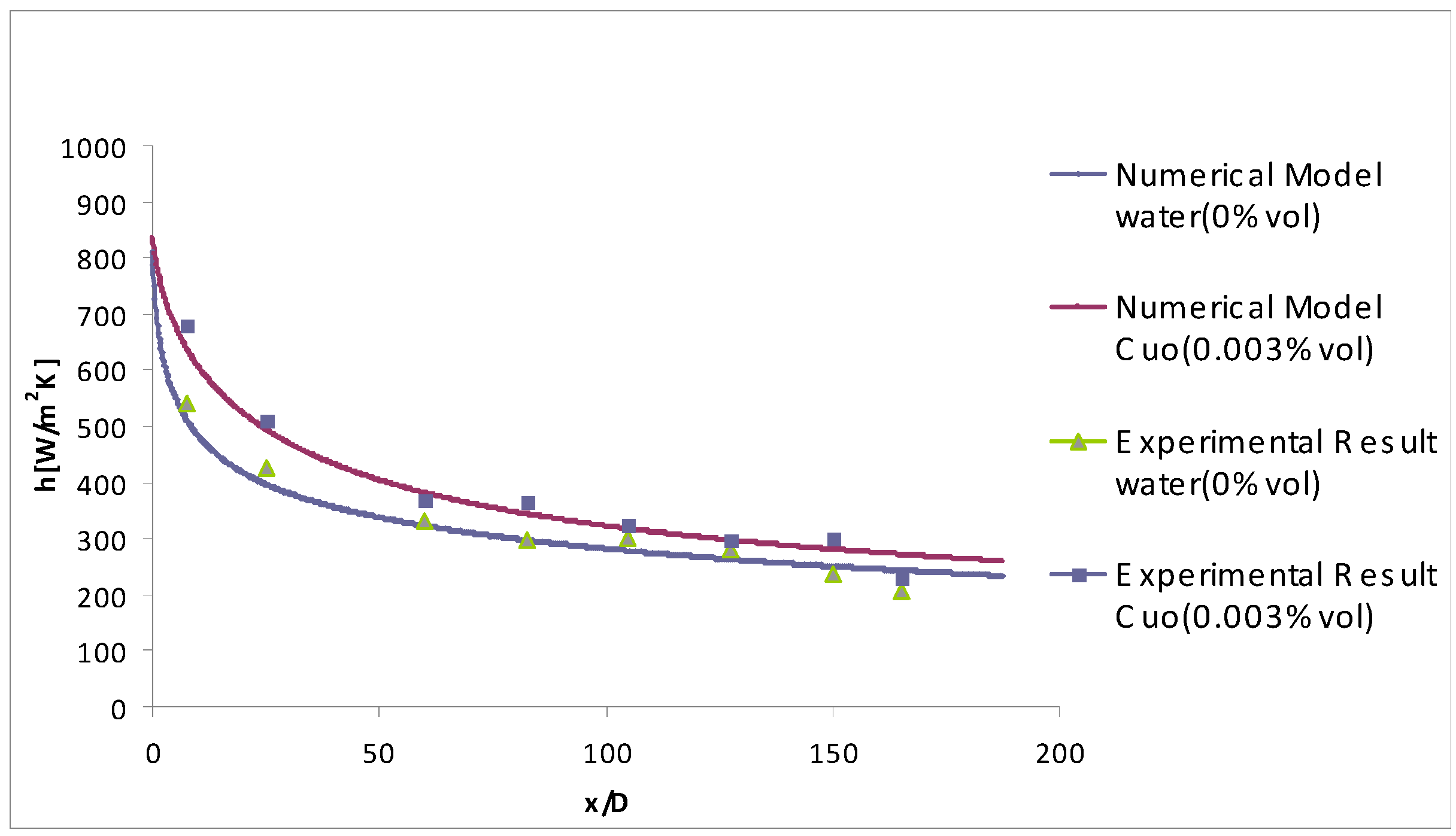
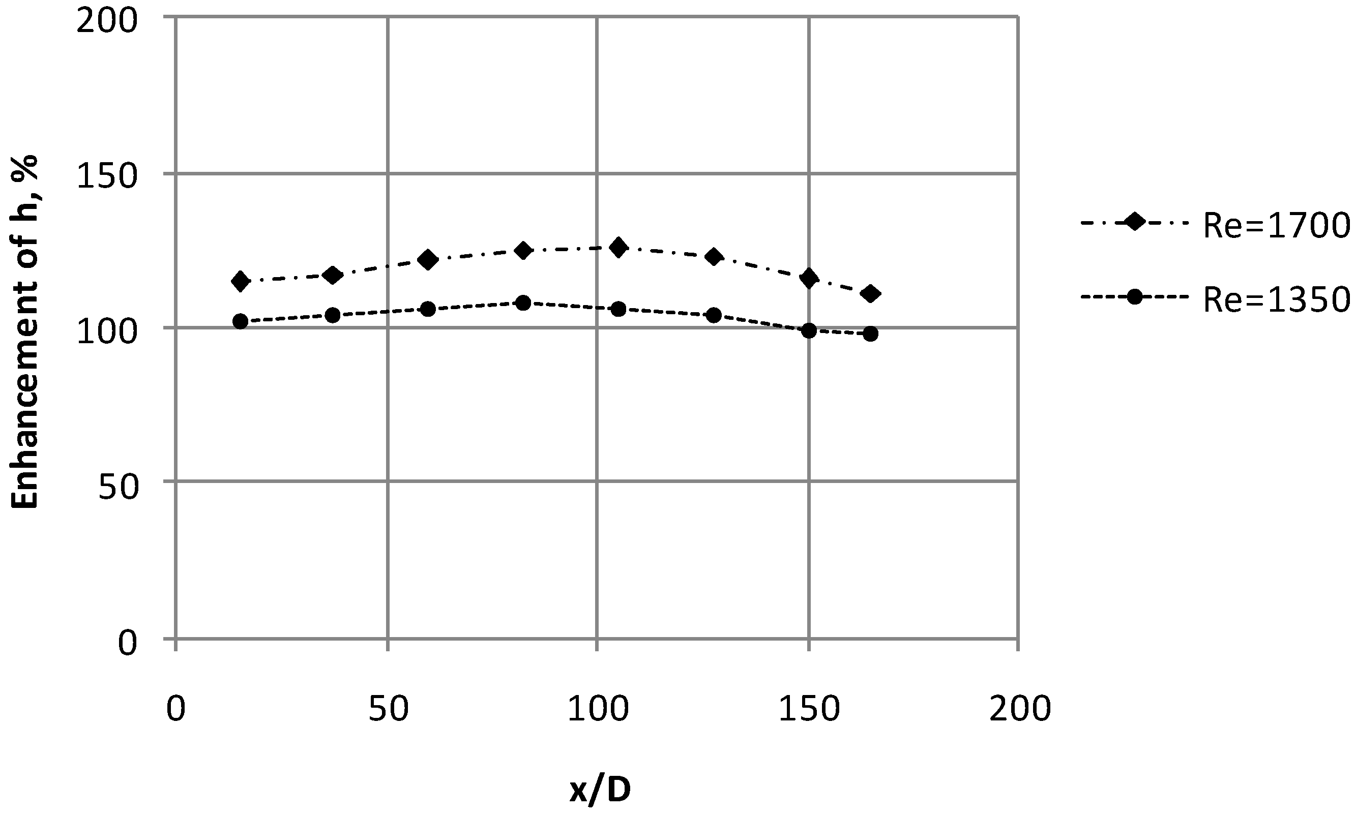
The presence of nanoparticles increases the convective heat transfer coefficient by 8% than that of the original base fluid under the same Reynolds number; and the increase is significant even though the concentration is less. At a given concentration the enhancement of heat transfer coefficient increases in the entrance region and decreases with the axial distance.
The thermo-physical properties of nanofluids and chaotic movement of ultrafine particles are considered to be the important factors for an increase in heat transfer rate.
Considerable fluctuations in the wall temperature readings at high heat fluxes indicate flow oscillations because of the random motion (Brownian motion) of the particles that cause changes in the instantaneous values of local nanofluid temperature and heat transfer rate.
The energy exchange of the nanoparticle-fluid contacts increases as the temperature increases. This rise in temperature influences the particle collisions in the nanofluid resulting in an enhancement of thermal conductivity and in turn brings about higher heat transfer coefficient. More study will determine the extent of such temperature-dependant behavior. Such a type of studies could provide new findings which will be used for determining the importance of particle motion in controlling thermal transport behavior.
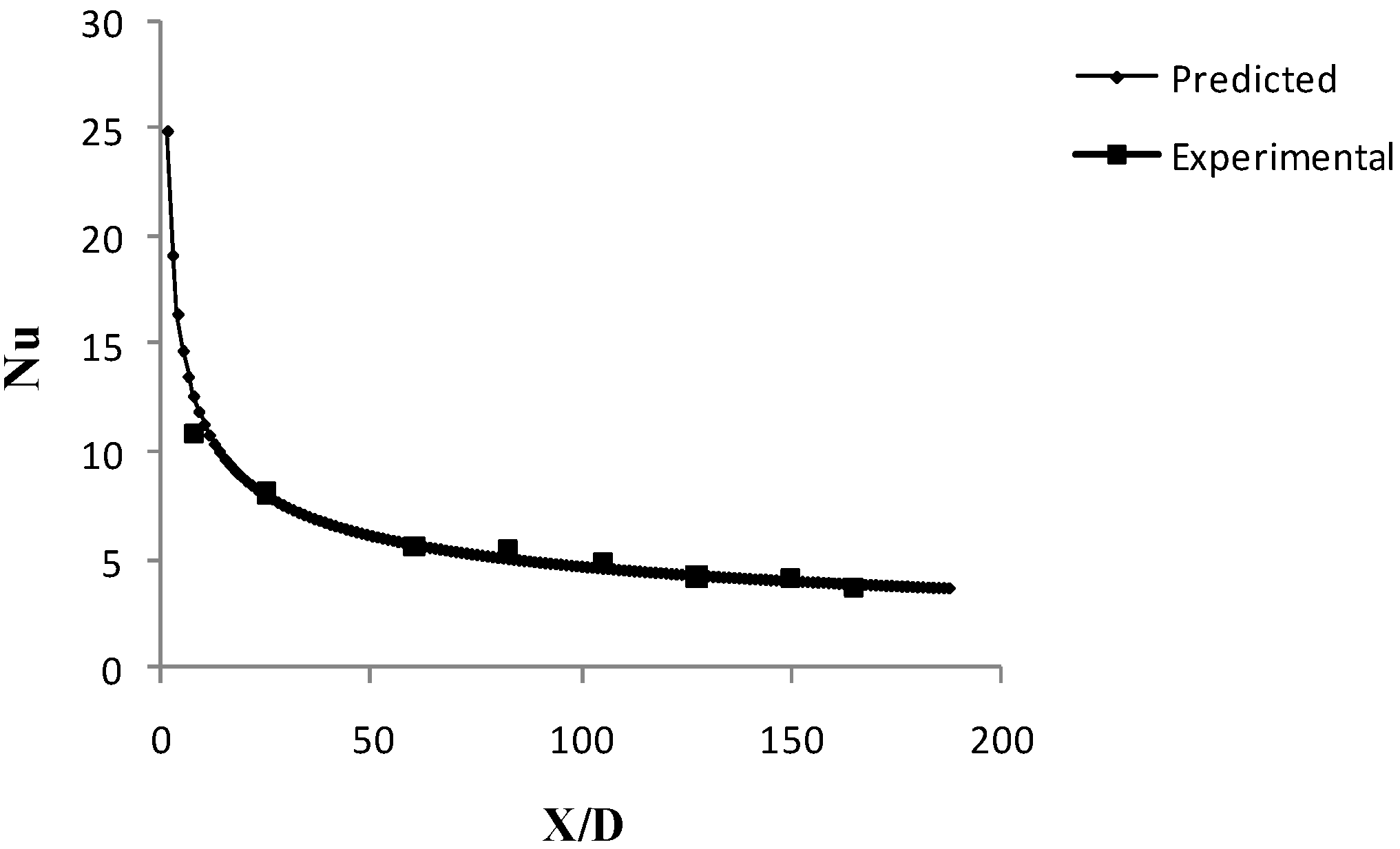
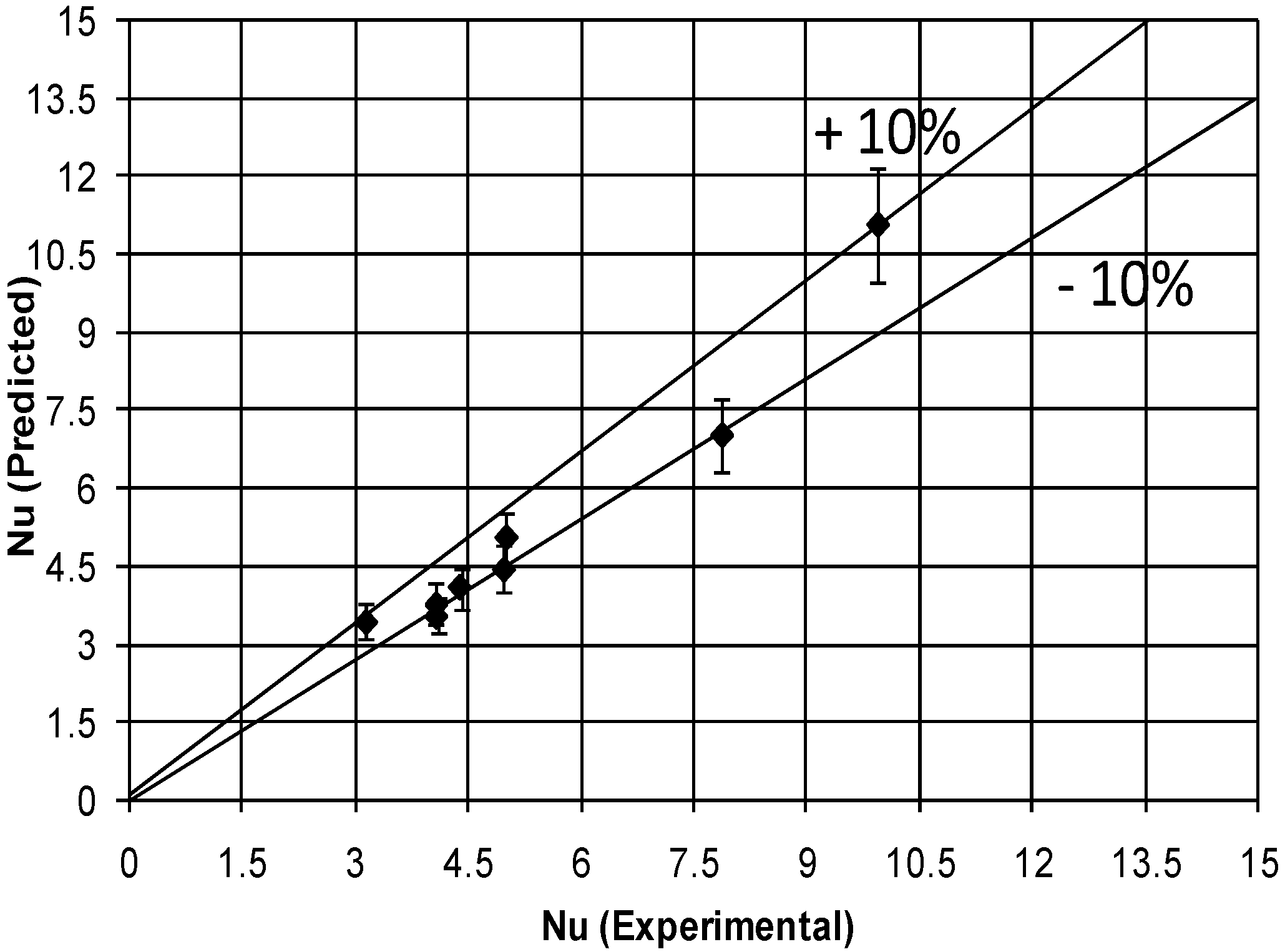
Based on the experimental data a correlation for convective heat transfer coefficient of nanofluids, N u = 0.155   R e 0.59 P r 0.35 ( D / x ) 0.38 based on transport property and D/x for an 8 mm tube has been evolved.
In conclusion, this study has provided a clear insight into the thermal behavior of a nanofluid under convective conditions in the context of a confined tube flow. The results found can easily be leveraged for various practical heat transfer and thermal applications to bring about a dynamic advancement in the field of nano scale heat transfer.

Acknowledgements

The authors would like to thank Prof. Jacopo Buongiorno, Massachusetts Institute of Technology, Cambridge, MA, for rendering a helpful review and constructive suggestions during the above research work.

Nomenclature

A
cross sectional area, m2
Cp
specific heat, J/kg K
d
tube diameter, m
h
heat transfer coefficient, W/m2 K
k
thermal conductivity, W/m K
m
mass flow rate, kg/s
Nu
Nusselt number,
Pr
Prandtl number,
q"
heat flux, W/m2
Re
Reynolds number
T
temperature, oC

Greek Symbols:

β
thermal dispersion coefficient, N/m2 K
φ
volume fraction
ρ
density, kg/m3
µ
dynamic viscosity, kg/m s

Subscripts: 

f
bulk fluid
nf
nanofluid
w
tube wall
x
axial distance
bf
base fluid
i
inner wall
o
outer wall

References and Notes

  1. Hwang, Y.J.; Ahn, Y.C.; Shin, H.S.; Lee, C.G.; Kim, G.T.; Park, H.S.; Lee, J.K. Investigation on characteristics of thermal conductivity enhancement of nanofluids. Curr. Appl. Phys. 2006, 6, 1068–1071. [Google Scholar] [CrossRef]
  2. Tuckerman, D.B.; Pease, R. F. W. High Performance Heat Sinking for VLSI. IEEE Elec. Dev. Lett. 1981, 2, 126–129. [Google Scholar] [CrossRef]
  3. Liu, M.-S.; Lin, M.C.-C.; Huang, I-T.; Wang, C.-C. Enhancement of thermal conductivity with carbon nanotube for nanofluids. Int. Commun. Heat Mass Transfer 2005, 32, 1202–1210. [Google Scholar] [CrossRef]
  4. Lee, S.; Choi, S.; Lee, S.; Eastman, J. Measuring thermal conductivity of fluids containing oxide nanoparticles. J. Heat Transfer 1999, 121, 280–289. [Google Scholar] [CrossRef]
  5. Masuda, H.; Ebata, A.; Teramae, K.; Hishinuma, N. Alteration of thermal conductivity and viscosity of liquid by dispersion of ultra-fine particles. Netsu Bussei (Japan) 1993, 4, 227–233. [Google Scholar] [CrossRef]
  6. Eastman, J.; Choi, S.; Li, S.; Yu, W.; Thompson, L. Anomalously increased effective thermal conductivities of ethylene glycol-based nanofluids containing copper nanoparticles. Appl. Phys. Lett. 2001, 78, 718–720. [Google Scholar] [CrossRef]
  7. Xie, H.; Wang, T.; Xi, J.; Liu, Y.; Ai, F.; Wu, Q. Thermal conductivity enhancement of suspensions containing nanosized alumina particles. J. Appl. Phys. 2002, 91, 4568–4572. [Google Scholar] [CrossRef]
  8. Das, S.; Putra, N.; Thiesen, P.; Roetzel, W. Temperature dependence of thermal conductivity enhancement for nanofluids. J. Heat Transfer 2003, 125, 567–574. [Google Scholar] [CrossRef]
  9. Patel, H.; Das, S.; Sundararajan, T.; Sreekumaran, A.; George, B.; Pradeep, T. Thermal conductivities of naked and monolayer protected metal nanoparticle based nanofluids: Manifestation of anomalous enhancement and chemical effects. Appl. Phys. Lett. 2003, 83, 2931–2933. [Google Scholar] [CrossRef]
  10. Choi, S.; Zhang, Z.; Yu, W.; Lockwood, F.; Grulke, E. Anomalously thermal conductivity enhancement of in nanotube suspensions. Appl. Phys. Lett. 2001, 79, 2252–2254. [Google Scholar] [CrossRef]
  11. Xie, H.; Lee, H.; Youn, W.; Choi, M. Nanofluids containing multiwalled carbon nanotubes and their enhanced thermal conductivities. J. Appl. Phys. 2003, 94, 4967–4971. [Google Scholar] [CrossRef]
  12. Choi, S.U.S. Enhancing thermal conductivity of fluids with nanoparticles, Developments and applications of non-Newtonian flows. ASME FED 231/MD 1995, 66, 99–103. [Google Scholar]
  13. Ahuja, A.S. Augmentation of heat transport in Laminar flow of polystyrene suspensions. I. Experiments and Results. J. Appl. Phys. 1975, 46, 408–3416. [Google Scholar]
  14. Ahuja, A.S. Thermal design of heat exchanger employing Laminar flow of particle suspensions. Int. J. Heat Mass Transfer 1982, 25, 725–728. [Google Scholar] [CrossRef]
  15. Pak, B.C.; Young, C.I. Hydrodynamic and heat transfer study of dispersed fluids with sub-micron metallic oxide particles. Exp. Heat Transfer 1998, 11, 151–170. [Google Scholar] [CrossRef]
  16. Eastman, J.A.; Choi, S.U.S.; Li, S.; Soyez, G.; Thompson, L.J.; DiMelfi, R.J. Novel thermal properties of nanostructure materials. Mater. Sci. Forum 1999, 312, 629–34. [Google Scholar] [CrossRef]
  17. Xuan, Y.M.; Li, Q. Investigation on convective heat transfer and flow features of nanofluids. J. Heat Transfer 2003, 125, 151–155. [Google Scholar] [CrossRef]
  18. Xuan, Y.; Li, Q. Flow and Heat Transfer Performances of Nanofluids inside Small Hydraulic Diameter Flat Tube. J. Eng. Thermophys. 2004, 25, 305–307. [Google Scholar]
  19. Wen, D.S.; Ding, Y.L. Experimental investigation into convective heat transfer of nanofluids at the entrance region under laminar flow conditions. Int. J. Heat Mass Transfer 2004, 47, 5181–5188. [Google Scholar] [CrossRef]
  20. Faulkner, D.; Rector, D.R.; Davison, J.J.; Shekarriz, R. Enhanced Heat Transfer through the Use of Nanofluids in Forced Convection. Proc. ASME Heat Transfer Div. 2004, 219–224. [Google Scholar]
  21. Zhou, D.W. Heat transfer enhancement of copper nanofluid with acoustic cavitation. Int. J. Heat Mass Transfer 2004, 47, 3109–3117. [Google Scholar] [CrossRef]
  22. Yang, Y.; Zhang, Z.G.; Grulke, E.A.; Anderson, W.B.; Wu, G.F. Heat transfer properties of nanoparticles-in-fluid dispersions (nanofluids) in laminar flow. Int. J. Heat Mass Transfer 2005, 48, 1107–1116. [Google Scholar] [CrossRef]
  23. Li, Q.; Xuan, Y.; Jiang, J.; Xu, J.W. Experimental Investigation on Flow and Convective Heat Transfer Feature of a Nanofluid for Aerospace Thermal Management. J. Astronautics 2005, 26, 391–394. [Google Scholar]
  24. Zeinali Heris, S.; Etemad, S.G.; Nasr Esfahany, M. Experimental investigation of oxide nanofluids laminar flow convective heat transfer. Int. Commun. Heat Mass Transfer 2006, 33, 529–535. [Google Scholar] [CrossRef]
  25. Zeinali Heris, S.; Nasr Esfahany, M.; Etemad, S.G. Experimental investigation of convective heat transfer of Al2O3/water nanofluid in circular tube. Int. J. Heat Fluid Flow 2007, 28, 203–210. [Google Scholar] [CrossRef]
  26. Ding, Y.; Alias, G.; Wen, D.; Williams, Richard A. Heat transfer of aqueous suspensions of carbon nanotubes (CNT nanofluids). Int. J. Heat Mass Transfer 2006, 49, 240–250. [Google Scholar] [CrossRef]
  27. Lai, W.Y.; Duculescu, B.; Phelan, P.E.; Prasher, R.S. Convective heat transfer with nanofluids in a single 1.02-mm tube. In Proc. ASME Int. Mech. Eng. Congress and Exposition (IMECE 2006), Chicago, IL, USA, 2006.
  28. Jung, J.-Y.; Oh, H.S.; Kwak, H.Y. Forced convective heat transfer of nanofluids in microchannels. In Proc. ASME Int. Mech. Eng. Congress and Exposition (IMECE 2006), Chicago, IL, USA; 2006. [Google Scholar] [CrossRef]
  29. Ding, Y.L.; Chen, H.S.; He, Y.R.; Alexei, L.; Mahboubeh, Y.; Lidija, Š.; Butenko Yuriy, V. Forced convective heat transfer of nanofluids. Adv. Powder Technology. 2007, 18, 813–824. [Google Scholar] [CrossRef]
  30. Wesley, W.; Buongiorno, J.; Hu, L.-W. Experimental Investigation of Turbulent Convective Heat Transfer and Pressure Loss of Alumina/Water and Zirconia/Water Nanoparticle Colloids(Nanofluids) in Horizontal Tubes. J. Heat Transfer. 2008, 130, 1–6. [Google Scholar]
  31. Chen, H.S.; Yang, W.; He, Y.R.; Ding, Y.L.; Zhang, L.L.; Tan, C.Q.; Lapkin, A.A.; Bavykin, D.V. Heat transfer and flow behaviour of aqueous suspensions of titanate nanotubes (nanofluids). Powder Technol. 2008, 183, 63–72. [Google Scholar] [CrossRef]
  32. Maiga Sidi, E.; Palm, S.J.; Tam, N.C.; Gilles, R.; Nicolas, G. Heat transfer enhancements by using nanofluids in forced convection flows. Int. J. Heat Fluid Flow 2005, 26, 530–546. [Google Scholar] [CrossRef]
  33. Anoop, K.B.; Patel, H.E.; Sundararajan, T.; Das, S.K. Numerical study of convective laminar heat transfer in nanofluids. Int. Heat Transfer Conf. 2006. (http://dx.doi.org/)10.1615/IHTC13.p8.110. [Google Scholar] [CrossRef]
  34. Xuan., Y.; Roetzel, W. Conceptions for heat transfer correlation of nanofluids. Int. J. Heat Mass transfer. 2000, 43, 3701–3707. [Google Scholar] [CrossRef]
  35. Drew, D.A.; Passman, S.L. Theory of Multicomponent Fluids; Springer: Berlin, 1999. [Google Scholar]
  36. Kodhandaraman, C.P.; Subramanyan, S. Heat Mass Transfer Data Book; New Age Int. (P) Ltd: New Delhi, 1989; Reprint 2007. [Google Scholar]
  37. Eastman, J.A.; Phillpot, S.R.; Choi, S.U.S.; Keblinski, P. Thermal Transport in Nanofluids. Annu. Rev. Mater. Res. 2004, 34, 219–246. [Google Scholar] [CrossRef]
  38. Buongiorno, J. Convective Transport in Nanofluids. J. Heat Transfer. 2006, 128, 240–250. [Google Scholar] [CrossRef]
  39. Wang, B.X.; Zhou, L.P.; Peng, X.F.; Zhang, X.X. Enhancing the effective thermal conductivity of liquid withdilute suspensions of nano particles. In 15th Symposium on Thermophysical Properties; Boulder, CO, USA, June 2003. [Google Scholar]

