
Determination of the Theoretical and Actual Working Volume of a Hydraulic Motor—Part II (The Method Based on the Characteristics of Effective Absorbency of the Motor)


Faculty of Mechanical Engineering and Ship Technology, Gdansk University of Technology, 80-233 Gdansk, Poland
Energies 2021, 14(6), 1648; https://doi.org/10.3390/en14061648
Submission received: 4 February 2021
/
Revised: 24 February 2021
/
Accepted: 11 March 2021
/
Published: 16 March 2021
(This article belongs to the Special Issue Advances in Fluid Power Systems)
Abstract
:In this article, the second method of determination of the theoretical and actual working volume of a hydraulic motor is described. The proposed new method is based on the characteristics of effective absorbency of the motor. The effective absorbency has been defined as the ratio of flow rate in a motor to the rotational speed of the motor’s shaft. It has been shown that the effective absorbency is a nonlinear function of the rotational speed and nonlinear function of the pressure drop in the motor’s working chambers. Furthermore, it has been proven that the actual working volume of a motor is a function of a third degree of pressure drop in the motor’s working chamber. The actual working volume should be taken to assess the mechanical and volumetric energy losses in the motor. Furthermore, the influence of the flowmeter location in the measurement system and the compressibility of liquid on the result of the theoretical and actual working volume calculation was also taken into account and is described in this article. The differences in the assessment of the volumetric efficiency assuming the theoretical and actual working volume was also shown.
1. Introduction
For users and designers of a hydraulic system, the volumetric and pressure-mechanical efficiency of the hydraulic positive displacement machine (motor or pump) is very important [1,2,3,4,5,6]. So far, these efficiencies are calculated based on the theoretical working volume qt. The theoretical working volume qt is a parameter that corresponds to the volume of liquid flowing without energy losses through the positive displacement machine during one full rotation of the shaft. The qt is determined from experimental data. The value of qt is constant in the whole range of the rotational speed n and the pressure drop Δp in a positive displacement machine [7,8,9,10,11,12,13,14].
It happens that the geometric working volume qg is used instead of the qt to calculate the energy losses in positive displacement machines. The qg is calculated from geometrical dimensions of the working mechanism using special mathematical formulas which are different for various types of positive displacement machines [15]. The theoretical working volume qt does not have to be equal to the geometrical working volume qg and is usually not equal. The differences can be up to several percent [7,8,15]. The main reasons for these differences are:
- Looseness in the working mechanism,
- errors in the manufacturing of the components,
- assembly errors,
- changes in ambient temperature,
- changes in working liquid temperature, etc.
If the qt corresponds to the volume of liquid flowing without energy losses through the motor during one full revolution of the motor shaft, then the qt should be determined by taking into consideration the pressure drop Δpi in the working mechanism and the liquid compressibility β. If the liquid compressibility β is taken into account, then the location of a flow meter in the measuring system is of great important [12]. However, in practice, it is assumed that the pressure drop Δp in a motor is equal to the pressure drop Δpi in the motor working chambers, and the liquid compressibility β is neglected [7,8,13,14].
In a loaded hydraulic motor, the working chambers are resiliently deformed (due to the pressure difference Δpi). The working chamber under the pressure will have a bigger volume. Then, the working volume can differ from the geometric working volume qg [8,12]. The working volume under the pressure difference Δpi was called the actual working volume qr [12]. Therefore, qr is a function of the pressure drop Δpi. It will be better to assume qr instead of qt and qg to assess the losses in a hydraulic motor. Furthermore, in [12], it was shown that qt and qr should be determined by taking into account the liquid compressibility β. The precision determination qr allows us to more precisely assess energetic losses and more precisely assess the clearances in the hydraulic motor working mechanism.
So far, there have been only a few publications on the methodology of determination of the theoretical working volume qt of a displacement machine. The first method was described by Wilson in 1950 [16] and Schlosser and Hilbrands in 1963 [9,10,11]. This method was corrected and described by Toet in 1970 [13] and in 2019 [14], and also by Balawender in 1974 [8]. These authors described in their publications the method of determining the qt based on the characteristics (Q = f(n)Δp=const.) of flow rate Q in a motor as a function of rotational speed n at constant pressure drop Δp in this motor. The Toet and Balawender method have been referred in literature, like in [17,18,19,20].
The latest article on the methodology of determination the theoretical working volume was published in 2020 [12]. In this publication, the influence of liquid compressibility β and the influence of pressure drop Δpich in the motor internal channels on the qt are described.
The second method of determining the qt was proposed by Balawender [8]. This method is based on the characteristics qe = f(n−1)Δp=const. of effective absorbency qe as a function of rotational speed n at constant pressure drop Δp in the motor. Thus, the influence of pressure drop in the motor internal channel and liquid compressibility β were neglected.
According to ISO 8426, the theoretical working volume qt is defined as a ratio of flow rate increment ΔQ to the corresponding rotational speed increment Δn [21]. The method according to ISO standard is the simplest of all the known methods and gives an inaccurate result.
There were also attempts to calculate the qt by analyzing the flow rate for a single pump chamber [22]. However, this method becomes problematic to use in practice.
For this purpose, in the following sections are described:
- (a).
- Known methods for determining the theoretical working volume qt;
- (b).
- the proposed new method of determining the theoretical qt and actual working volume qr based on the characteristics qe = f(n)Δpi=const. (taking into account the compressibility β of liquid and the pressure drop Δpich in the internal channel of a motor);
- (c).
- the practical implementation of the proposed method;
- (d).
- the experimental tests of the hydraulic satellite motor for confirming the correctness of the proposed new method;
- (e).
- comparing the result of new method with the result of Balawender’s method.
2. The Analysis of Flow Rate in a Hydraulic Motor
In order to determine the theoretical working volume qt of the motor, it is necessary to measure and analyze the flow rate in this motor. Balawender recommends using two flow meters for this—one located in the inflow line of the motor and second in the outflow line (Figure 1) [7,8], whereas Toet indicates only one flowmeter located in the inflow line of the motor [13,14].
2.1. Balawender’s Model
- Qg, Qu, Qk, QC—the components of the flow rate Q lineary dependent on the geometric volume qg, the pressure drop Δp, and rotational speed n;
- QLi—the internal leakage (from the high-pressure working chambers to the low-pressure working chambers):
- QLe—the external leakage linearly dependent on the theoretical working volume qt and the pressure drop Δp (leakage from the working chambers on the outside of the motor—leakage from the motor body by the third hose):
2.2. Sliwinski’s Model
The Balawender’s model of flow rate in a hydraulic motor is a general model. This model does not take into account the construction parameters of the motor. In this way, this model can try to adapt to any type of hydraulic motor, which is his advantage. On the other hand, the small accuracy is a disadvantage of this model. However, Sliwinski recommends using the model of flow rate in the motor based on analysis of construction and analysis of phenomena in the motor. Therefore, the type of motor and its construction is important. In this way, the basis for development of the model of flow rate in the motor is development of the model of volumetric losses in this motor. The mathematical model of volumetric losses, dedicated to the satellite motor (described in Section 6.1), is following [23,24]:
where:
where:
- QLe—external leakage;
- C1, C2, C3, Cq, Cid, A1, A2, K, and γ—coefficients;
- β—the degree of laminarity of the flow;
- ν—kinematic viscosity of liquid;
- m—teeth module;
- h—equivalent axial clearances of the rotor and satellites;
- hS—axial clearance of the satellites;
- H—height of the working mechanism (equal to height of curvature);
- DO—the diameter of inlet and outlet holes in the commutation plate.
The flow rate Q in the motor is:
where Qt is the theoretical flow rate in the motor:
If the influence of liquid compressibility β on the flow rate measurement result is omitted, then:
If QLe = 0 then:
3. The Pressure Drop in the Motor Working Chambers
The pressure difference Δpi in the motor working chambers has an influence on the volumetric losses in the motor—as indicated above. This Δpi is also taken into account during the determination of the theoretical working volume qt of a motor. However, direct measurements of this pressure are very difficult or impossible. It is much easier to determine the Δpi by measuring the pressure drop in Δpich in the internal channel of the motor. Then [12,24,27]:
4. Known Method to Determine the Theoretical Working Volume
4.1. Balawender’s and Toet’s Method—Based on Characteristics Q = f(n)
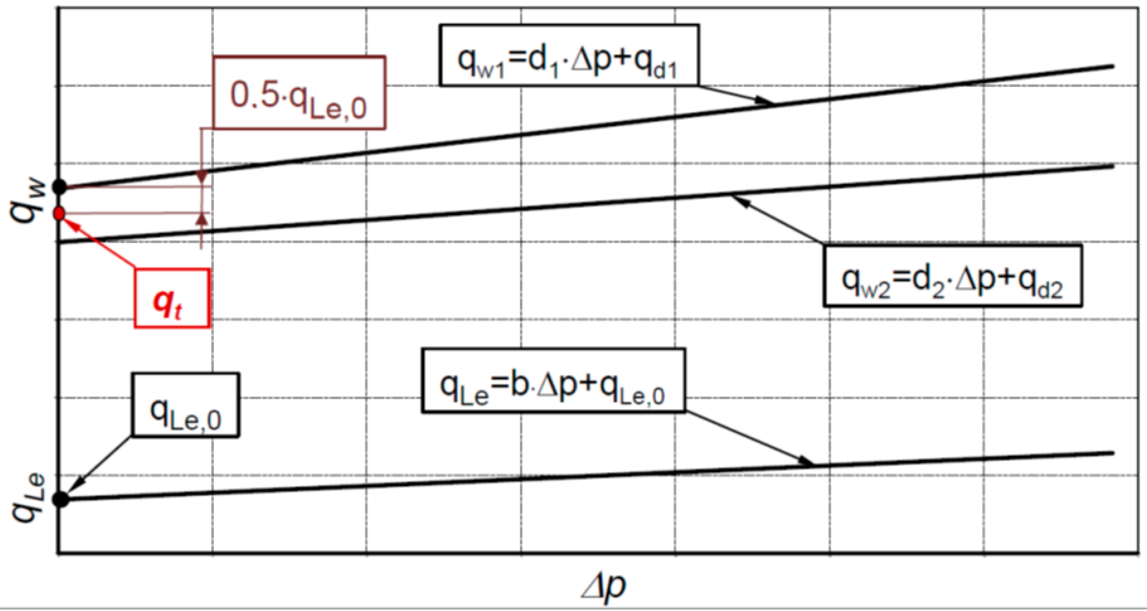
Balawender and Toet claim that the flow rate Q (Q1 or Q2) in a hydraulic motor is described by a linear function [7,8,12,14]:
where:
Balawender suggests testing the motor in the range of speed nmax ≤ 3nmin. The nmin is the minimum speed at which the motor can work stably. The nmax is the maximum speed for which the assumption Δpi ≈ Δp is true [7,8,12]. If Δpi ≈ Δp, then Equations (16) and (17) take the form:
In practice, only one flowmeter is applied in measuring system. Then qt = qt1 or qt = qt2.
4.2. The Influence of Working Pressure on Working Volume
According to Balawender and Toet, the geometric working volume qg is a linear function of pressure [7,8,14]:
This is a simplification, of course. Similarly, Sliwinski assumed that the increase in the positive displacement machine’s working volume is a function of pressure drop in the motor working chambers and can be described by the Formula (9).
The influence of working pressure on the working volume was also noticed by Osiecki during the test of prototype of axial piston pump with cam-driven unit [6]. With increasing the load of the pump, the working volume of the pump also increased. Thus, it can be seen that the adoption of the theoretical working volume qt can introduce a significant error in the evaluation of the losses in displacement machines. Therefore, in [12], it has been shown that is not advisable to assume qt for the assessment of losses in the motor in the whole range of its load. However, it is better and more precise to use the actual working volume qr defined as [12]:
4.3. Balawender’s Method—Based on Characteristics qe = f(n)Δp=const.
In his considerations, Balawender omits the pressure drop Δpich in internal channels of the motor and assumes: Δpi ≈ Δp.
If the rotational speed n increases, then the leakage QL has a smaller share in the effective flow rate in the motor. In effect [8]:
Similarly, if the Δp decreases, then the leakages QL also decreases. Then the qt is calculated from the following formulas [6,8]:
In practice, only one flowmeter is applied in the measuring system. Then qt = qt1 or qt = qt2.
4.4. The Influence of the Flow Meter Location in the Measurement System on the Flow Rate in the Hydraulic Motor
4.4.1. Toet’s Method
Toet recommends placing a flow meter in the inlet line to a hydraulic motor. Then the flow meter measures total flow rate, including the external leakage. However, if the flow meter is located in the low-pressure line, the influence of the liquid compressibility on the flow rate should be taken into account. Then [14]:
where K1, K2, K3, K4, K5 are constants. That is, the effect of liquid compressibility is related to the geometric working volume qg. Furthermore, the influence of liquid compressibility on the leakage QL is neglected. Therefore, this assumption introduces some error in calculations of the theoretical working volume qt.
4.4.2. Balawender’s Method
Balawender recommends locating the flow meter in two places of hydraulic circuit. The first place is the high-pressure line of the motor. Then Q(p1) ≈ Q1 [8]. The second place is the low-pressure line of the motor. For this location of flow meter [8]:
where κ is the correction coefficient. For oil, for t = 40 °C, the value of the coefficient is [8]:
and Δp is expressed in [MPa].
Finally, in a practical approach to determine the theoretical working volume, both Toet and Balawender simplify the problem, and the effect of the flow meter location in the measuring system is finally neglected.
4.4.3. Sliwinski’s Method
The flow rate Q(pH) related to the pressure pH in the high-pressure working chamber is possible to calculate depending on the location of a flow meter in measuring system. Thus:
- (a).
- (b).
- For the flow meter located in the low-pressure line to the motor (Figure 1), the flow rate is:where:
- K—the bulk modulus of non-aerated oil at atmospheric pressure po;
- Xo—the amount of non-dissolved air in the oil at atmospheric pressure po;
- p—the absolute pressure;
- n—the polytrophic exponent;
- m—the coefficient of the influence of pressure p on the bulk modulus K.
5. New Method of Determining the Theoretical and Actual Working Volume Based on the Characteristics of Effective Absorbency of the Motor
In the above described Balawender’s method of determining theoretical working volume, it is assumed that Δpi = Δp. That is, the pressure drop Δpich in internal channels of a motor is omitted. This simplification can have the influence on the value of theoretical working volume qt of the motor. Furthermore, Balawender assumed that the volumetric losses QL in a motor are linear function of rotational speed n (Section 2.1). Whereas, the analysis of volumetric losses in the motor, carried out by Sliwinski, show that these losses are a nonlinear function of speed n (Formula (9)). Furthermore, various researchers argue that the increase in working volume of a motor is a linear function of pressure drop in the motor (Formulas (9) and (25)) [7,8,13,14]. This is a simplification, of course. In fact, the motor’s working chamber is a spatial element, and each of its dimensions changes linearly under the influence of pressure. Therefore, the change in working volume of a motor is a nonlinear function of the pressure drop Δpich in its working chamber.
In the below described new method of determining the theoretical working volume qt, it is assumed:
- Δpi instead Δp;
- nonlinear dependence of volumetric losses QL on rotational speed n;
- nonlinear dependence of increasing in working volume Δq on pressure drop Δpi;
- the compressibility β of the liquid, that is the measured flow rate is compensated to the pressure in the filled chamber of the motor (the location of flowmeter in the test stand is included).
5.1. The Increase in Working Volume
In publications [7,8,23,24] and in Section 2.2, it is written that the rotational speed n has an influence on the increase in volumetric losses Δq (Formulas (8) and (9)). This is because of the movement of working mechanism elements within the slack. This movement causes an additional increase in working volume. In effect, additional volumetric loss is created depending on the speed. Furthermore, the increase in working volume Δq is a nonlinear function of pressure drop Δpi [23,24]. So, the increase in working volume Δqg caused by the pressure drop Δpi in the working chamber cannot be the reason of the volumetric losses in a motor. Therefore, Formula (9) is inaccurate, and instead of it, the following is proposed:
where:
5.2. The Actual Working Volume of a Loaded Motor
In [12], it was shown that with a change in pressure drop Δpi in working chambers the working volume also is in change according to formula:
The qr was called the actual working volume. For Δpi = 0 is qr = qt. The value of qr is obtained experimentally. The determination of qr is possible only when the component of flow rate QC (caused by liquid compressibility) is eliminated (see Section 4.4).
5.3. Flow Rate in a Motor
Taking into account Formula (45), the flow rate in a motor should be described by:
where ΔqL is described by Formula (44).
It can be assumed that the flow rate Q is a linear function of rotational speed n of a motor. The flow rate Q is measured by flowmeter and in this way Formulas (12) and (13) are applied.
5.4. The Effective Absorbency
The effective absorbency qe of the motor should be calculated according to the following formulas:
Thus, after substitution (5), (8), (9), and (10) into (47) and (48), respectively, the following are obtained:
Therefore, the effective absorbency qe is a linear function of Δpi and nonlinear function of the inverse of rotational speed n of the motor. That is:
In addition, it is worth noting that in the case of flow meter located in the motor outflow line the component QLe is omitted (because is not measured).
5.5. Theoretical Working Volume
If rotational speed n of a motor increases, then the share of leakages QL in the general balance of flow rate Q in the motor decreases. Therefore, the value of qe, described by Formulas (49) and (50), strives to a certain value qr, namely:
If Δpi = 0, then Δqg = 0. Thus, the theoretical working volume can be defined as follows:
If the measurement of flow rate Q1 and Q2 are made using flow meters of the same type and class and the compressibility of liquid is taken into account, then the theoretical working volumes (expressed by Formulas (54) and (55)) should have the same value:
In practice, only one flowmeter is applied in measuring system. Then qt = qt1 or qt = qt2.
5.6. Practical Implementation of the New Method
The practical implementation of the methodology of determining the theoretical working volume qt based on the characteristics of Q = f(n)Δpi=const. were described in [12]. In this place it is worth once again present this implementation and adjust it to the proposed new method. So, in order to determine the theoretical qt and actual working volume qr it is necessary [12]:
- (a).
- To measure the flow Q1 or Q2 at a constant inlet temperature T1 and a constant pressure drop Δp for several values of n (no less than five). The measurement has to be taken once again using at least five different pressure drops Δp;
- (b).
- to determine the pressure drop Δpich in the internal channel of the motor;
- (c).
- to calculate the pressure drop Δpi in the working chamber of the motor for data from item (a) and item (b);
- (d).
- if the flow meter is located in the low-pressure line, the influence of the liquid compressibility should be taken into account, and the flow rate Q(pH) corresponding to the value of high-pressure pH in the working chamber should be calculated;
- (e).
- to plot the characteristics of qe = f(1/n)Δpi=const. and calculate the qr according to Formulas (52) or (53) for each Δpi;
- (f).
- to plot the characteristics of qr = f(Δpi) and calculate the trend line of qr with equation (equation in the form (45)). Finally, from the obtained the theoretical working volume qt should be read.
6. Results of Experimental Research
6.1. Tested Motor
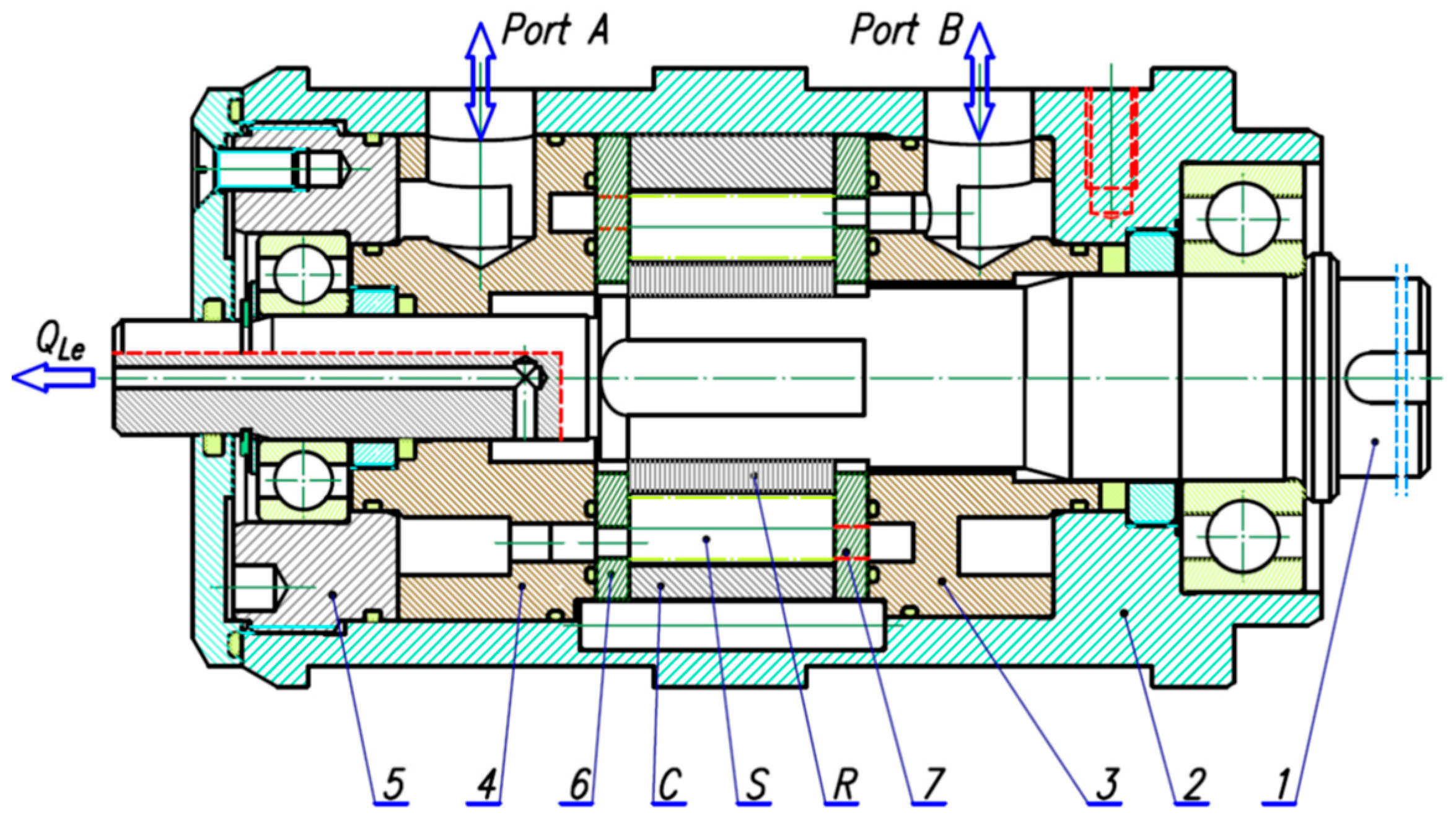
A prototype of a hydraulics satellite motor was selected for experimental tests. The construction of this motor is presented in Figure 6. The working mechanism of the satellite motor consists of internally toothed curvature C, externally toothed rotor R, and satellites S (Figure 7). The principle of operation of this working mechanism was widely described in other author’s publications, especially in [23,24,25,26,27,29,30].
The number of filling and emptying cycles of the working chambers per one rotation of the shaft is the product of the number nR of humps of the rotor and the number nC of humps of the stator. Thus, 24 cycles correspond to one shaft revolution [12,24].
The geometric working volume qg of the satellite mechanism depends on the number nR of humps of the rotor and the number nC of humps of the stator and is calculated according to the following formula [12,24]:
The following geometrical parameters characterized the satellite motor [12]:
- The height of the working mechanism H = 25 mm;
- the minimum area of the working chamber Amin = 26.11 mm2;
- the maximum area of the working chamber Amax = 83.51 mm2.
Thus, the geometric working volume of the satellite mechanism is qg = 34.44 cm3/rev.
6.2. The Test Stand and Measuring Apparatus
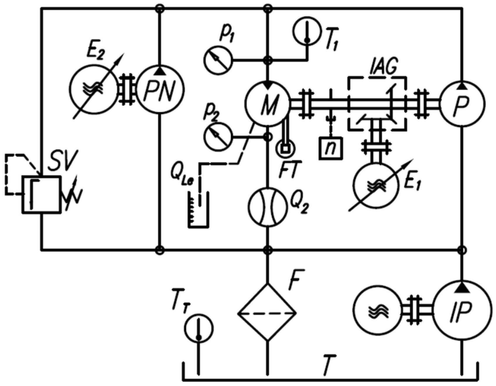
The satellite motor was tested on a test stand with power recuperation. The diagram of the measurement system of this test stand is shown in Figure 8.
Parameters of the motor measured during the test were summarized in Table 1.
In order to determine the working volume of the motor with the smallest possible error, it is important to maintain the setting of speed n, pressure drop Δp, and liquid temperature T1 with the least possible deviation. Thus [12]:
- For rotational speed n the deviation was ±0.1 rpm;
- for the pressure drop Δp the deviation was ±0.05 MPa;
- for the temperature in inflow port T1 the deviation was ±1.0 °C.
6.3. Working Liquid Parameters
The oil Total Azolla 46 was the working liquid during the satellite motor tests. The temperature in the inflow port of the motor was T1 = 43 °C which corresponds to the kinematic viscosity ν = 40 cSt and oil density ρ = 873 kg/m3.
6.4. Pressure Drop in Motor Internal Channels
6.5. Motor Output Flow Rate Characteristics
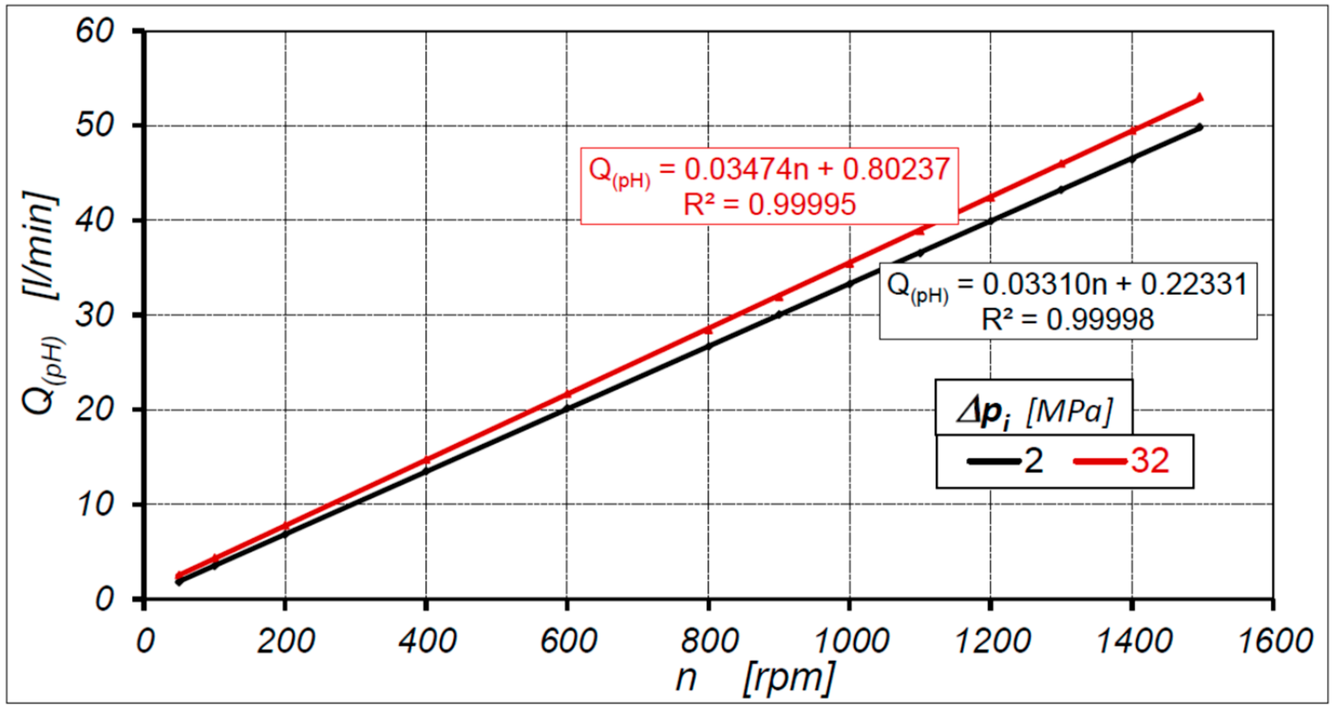
The satellite motor was tested in the range of rotational speed n = 50 ÷ 1500 rpm and in this speed range the characteristics Q2 = f(n) at Δp = const. were determined (Figure 10). In order to maintain the clarity of the graphs the characteristics are shown only for two extreme pressure drops in the motor, that is, for Δp = 2 MPa and Δp = 32 MPa.
The results of the experiment show that the characteristics of flow rate Q2 (at Δp = const.) are a linear function of rotational speed n, and they are compatible with theoretical characteristics presented in Figure 2. Therefore, the characteristics of Q2 can be described by Equation (19), as shown in Figure 10.
The value of external leakage QLe in the tested motor is no more than 0.06 L/min in the whole range of the motor load [12]. Due to a very small value, the leakage QLe was omitted.
In Figure 11, the characteristics of output flow rate Q2 at constant pressure drop Δpi in working chambers (for Δpi = 2 MPa and Δpi = 32 MPa) are shown. The Δpi was calculated according to Formulas (14) and (58) (that is was taken into account the pressure drop Δpich in the internal channels of the motor). The influence of liquid compressibility was omitted.
The flow rate Q(pH) related to the pressure pH in the high-pressure chamber of the motor was calculated (using the method described in Section 4.4.3—that is the liquid compressibility was taken into account) and shown in Figure 12 (for Δpi = 2 MPa and Δpi = 32 MPa).
6.6. Theoretical Working Volume According to Balawender’s Method
The characteristics of qe = f(n−1) determined according to Balawender’s method are shown in Figure 13.
According to the Balawender method, the theoretical working volume qt of the satellite motor is qt = 33.312 cm3/rev. (Figure 14).
6.7. Motor Theoretical Working Volume According to Proposed New Method
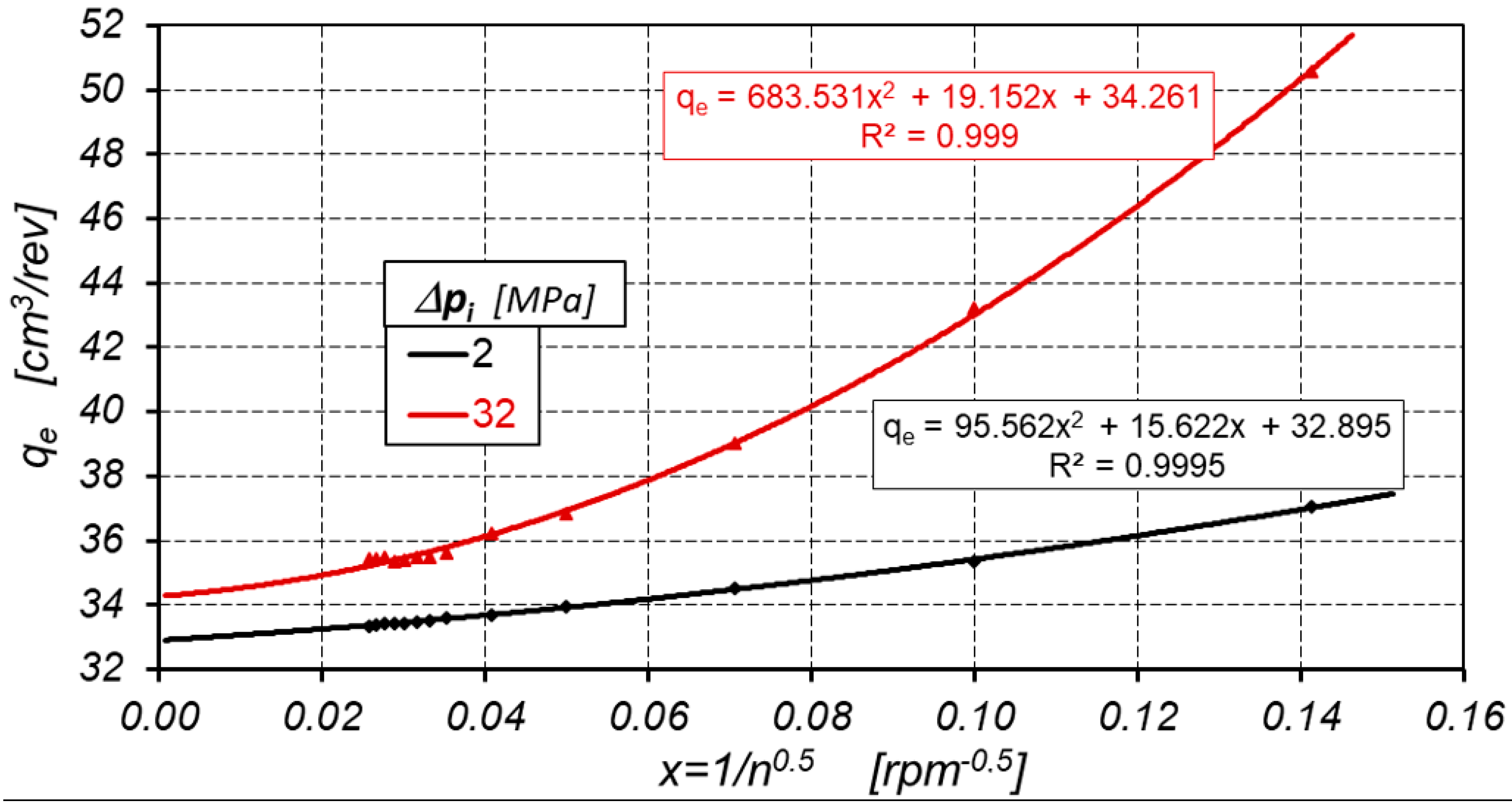
The characteristics of qe = f(n−0.5) determined according to the proposed new method are shown in Figure 15.
According to the new method, the theoretical working volume of the satellite motor is qt = 32.559 cm3/rev. (Figure 16).
7. Discussion
The theoretical analysis indicates that the flow rate in a hydraulic motor is a linear function of rotational speed (see Equations (10), (11), and (46)). All experimental data (see characteristics Q2 = f(n)Δp=const. in Figure 10, Q2 = f(n)Δpi=const. in Figure 11, and the characteristics of Q(pH) = f(n)Δpi=const. in Figure 12) were described by a linear trend line. In all trend line the correlation coefficient R2 between flow rate and rotational speed is close to one. A very high value of the correlation coefficient R2 is an effect of maintaining very precise parameters during the tests (described in Section 6.2). Furthermore the use of piston flow meter also contributed to the small scatter of the measurement results (the piston flow meter measured the average flow rate corresponding to more than 18 revolutions of the motor shaft). Thus, the results of the experimental research confirm the theoretical consideration and the flow rate in a hydraulic motor can be described by a linear function of rotational speed of a motor.
The value of the geometric working volume qg of the motor (34.44 cm3/rev) is greater than the theoretical working volume qt (32.5595 cm3/rev—calculated according to the proposed new method) by 1.8805 cm3/rev. That is, the qg is as much as 5.5% larger than the qt calculated according to the new method. The main reason of the difference between the qt and qg is technology of manufacturing of working mechanism elements. These elements are electrically cutting with wire with a certain allowance for finishing treatment (lapping). In this way, the qg is definitely smaller than qt.
The results of the experimental research confirm that:
- (a).
- It is possible to determine the pressure drop Δpich in internal channels and to calculate the pressure drop Δpi in working chambers;
- (b).
- the effective absorbency qe is a linear function of Δpi and non-linear function of the inverse of rotational speed n of the motor (formula (51) and Figure 15);
- (c).
- the rotational speed n of a hydraulic motor has no influence on the theoretical working volume qt;
- (d).
- the actual working volume qr is a third order polynomial function of pressure drop Δpi in working chambers of the motor (Figure 16). That is, Formula (45) is true. In the tested satellite motor is:
Furthermore it has been shown that is possible to determine the qr and qt including the influence of oil compressibility β.
The results of the experimental research show some difference (about 2.2%) in the theoretical working volume qt calculated using the new method (qt = 32.5595 cm3/rev.) and calculated using Balawender’s method (qt = 33.312 cm3/rev.). As the final result of the theoretical working volume should be adopted qt = 32.5595 cm3/rev. calculated according to the proposed new method. This decision can be justified by the fact that the Balawender method is a simplified method (adopted simplification: Δpi ≈ Δp, linear relationship between qe and 1/n (Figure 13) and linear relationship between D and Δp (Figure 14)). For users of hydraulic motor, the difference of 2.2% is not large and is usually imperceptible. However, for researchers of positive displacement machines, this difference can be significant because it directly influences on assessment of energetic losses in the motor.
Due to the fact the working volume increases under the pressure (Figure 16), the values of qr according to Formula (45) should be taken into account to calculate the volumetric and mechanical losses in a hydraulic motor.
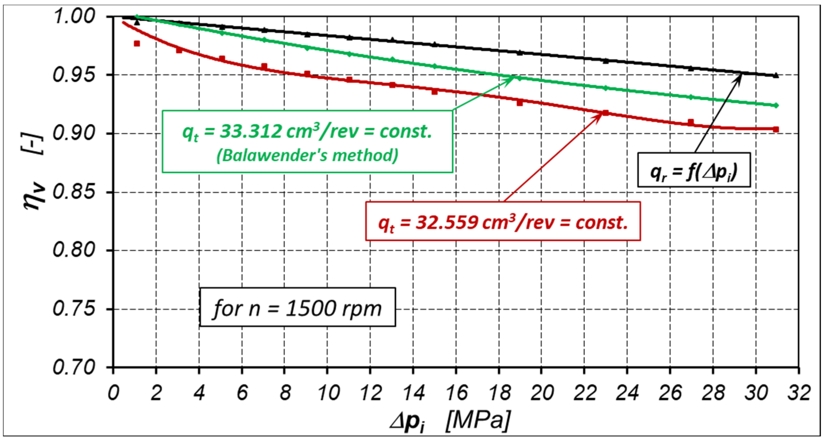
In the publicly available literature, the volumetric efficiency in a hydraulic motor is defined as:
For theoretical working volume calculated according to a simplified Balawender’s method, the volumetric efficiency ηv of the motor for Δp < 2 MPa (calculated according to the above formula) is larger than one (ηv > 1) (Figure 17). It has no physical sense, of course.
The theoretical working volume qt in all range of pressure drop Δp in a motor is adopted for calculation of losses in this motor and its efficiencies. In this way:
- The volumetric losses are overestimated;
- the mechanical losses are underestimated;
- the volumetric efficiency ηv is underestimated (Figure 17);
- the mechanical efficiency ηm is overestimated.
In the context of the aforementioned theoretical qt and actual working volume qr, instead of the theoretical flow rate Qt in a hydraulic motor, the actual flow rate Qr should be used, defined as:
where for Δpi = 0 is qr = qt and Qr = Qt. Whereas the volumetric efficiency for any Δpi is:
An example of the volumetric efficiency characteristics of the satellite motor for n = 1500 rpm, calculated according to Formulas (60) and (62), is shown in Figure 17.
Thus, it is necessary to take the actual working volume qr (as a function of pressure drop Δpi in working chambers) to calculate the losses in the hydraulic motor.
8. Summary
The above article presents a new methodology for determining the theoretical qt and actual qr working volume of a hydraulic motor. The proposed new method takes into account the pressure drop Δpich in the motor’s internal channels and the liquid compressibility (the location of the flow meter in the measurement system). The actual working volume qr is a non-linear function of the pressure drop Δpi in the working chambers. Therefore, the actual working volume qr should be taken to calculate the volumetric and mechanical losses, and also the volumetric and mechanical efficiency of the motor. In the tested satellite motor, the qr is changing about 3% in all range of Δpi. Is it a lot or a little? It is difficult to assess. Therefore, in order to be convinced of this, a satellite motor with a greater stiffness of the working mechanism should be built. The greater stiffness of the working mechanism is possible to obtain in two ways (separately or together):
- Mainly by increasing the diameter of the bypass,
- by changing the construction of the teeth in working mechanism elements.
The geometrical working volume of a satellite motor is definitely bigger than the theoretical working volume (about 5.5%). To explain this difference, it would be worthwhile to test the motor with reduced tip clearances and backlash clearances in the satellite mechanism. In this way, it will reduce the volume between the mating teeth of the satellite mechanism. This volume also has an impact on the process of pumping liquid through the working mechanism. The smaller this volume, the smaller the volumetric losses? The smaller an influence of rotational speed on the volumetric losses in a hydraulic motor? This thesis would require proof.
Funding
This research was funded by National Centre for Research and Development in Poland, grant number LIDER/35/102/L-2/10/NCBiR.
Conflicts of Interest
The author declares no conflict of interest.
References
- Antoniak, P.; Stosiak, M.; Towarnicki, K. Preliminary testing of the gear pump with internal gearing with modification of the sickle insert. In Proceedings of the Engineering Mechanics 2019, Svratka, Czech Republic, 13–16 May 2019. [Google Scholar]
- Kollek, W.; Osiński, P.; Warzyńska, U. The influence of gear micropump body asymmetry on stress distribution. Pol. Marit. Res. 2017, 24, 60–65. [Google Scholar] [CrossRef] [Green Version]
- Kollek, W.; Osinski, P.; Stosiak, M.; Wilczyński, A.; Cichon, P. Problems relating to high-pressure gear micropumps. Arch. Civ. Mech. Eng. 2014, 14, 88–95. [Google Scholar] [CrossRef]
- Patrosz, P. Influence of Gaps’ geometry change on leakage flow in axial piston pumps. In Lecture Notes in Mechanical Engineering; Cavas-Martínez, F., Chaari, F., Gherardini, F., Haddar, M., Ivanov, V., Kwon, Y.W., Trojanowska, J., di Mare, F., Eds.; Springer International Publishing: Geneva, Switzerland, 2020; pp. 76–89. [Google Scholar]
- Załuski, P. Experimental research of an axial piston pump with displaced swash plate axis of rotation. In Lecture Notes in Mechanical Engineering; Cavas-Martínez, F., Chaari, F., Gherardini, F., Haddar, M., Ivanov, V., Kwon, Y.W., Trojanowska, J., di Mare, F., Eds.; Springer International Publishing: Geneva, Switzerland, 2020; pp. 135–145. [Google Scholar]
- Osiecki, L. Commutation Units of Hydraulics Axial Piston Machines; Gdansk University of Technology Publishers: Gdansk, Poland, 2006. [Google Scholar]
- Balawender, A. Analiza Energetyczna i Metodyka Badań Silników Hydraulicznych Wolnoobrotowych (Energy Analysis and Methods of Testing of Low-Speed Hydraulic Motors); Scientific Book of the Gdansk University of Technology; Mechanika No. 54; Gdansk University of Technology Publishing House: Gdansk, Poland, 1988. [Google Scholar]
- Balawender, A. Opracowanie Metodyki Wyznaczania Teoretycznej Objętości Roboczej Pomp i Silników Hydraulicznych Wyporowych. (The Development of the Methodology for the Determination of the Theoretical Working Volume of Positive Displacement Pumps and Hydraulic Motors). Ph.D. Thesis, Gdansk University of Technology, Gdansk, Poland, 1974. [Google Scholar]
- Schlosser, W.M.J. Meten aan Verdringerpompen. Ph.D. Thesis, Technical Hogeschool Delft, Delft, The Netherlands, 1957. [Google Scholar]
- Schlosser, W.M.J.; Hilbrands, J.W. Das theoretische Hubvolumen von Verdrangerpumpen. Olhydraul. Pneum. 1963, 7, 133–138. (In German) [Google Scholar]
- Schlosser, W.M.J.; Hilbrands, J.W. Das volumetrische Wirkungsgrad von Verdrongerpumpen. Olhydraul. Pneum. 1963, 7, 469–476. [Google Scholar]
- Sliwinski, P. Determination of the theoretical and actual working volume of a hydraulic motor. Energies 2020, 13, 5933. [Google Scholar] [CrossRef]
- Toet, G. Die Bestimmung des theoretischen Hubvolumens von hydrostatischen Verdrangerpumen und Motoren aus volumetrischen Messungen. Olhydraul. Pnaum. 1970, 14, 185–190. [Google Scholar]
- Toet, G.; Johnson, J.; Montague, J.; Torres, K.; Garcia-Bravo, J. The Determination of the theoretical stroke volume of hydrostatic positive displacement pumps and motors from volumetric measurements. Energies 2019, 12, 415. [Google Scholar] [CrossRef] [Green Version]
- Stryczek, S. Napęd Hydrostatyczny (Hydrostatic Drive); WNT: Warszawa, Poland, 2005. [Google Scholar]
- Wilson, W.E. Positive Displacement Pumps and Fluid Motors; Publication Corporation: New York, NY, USA, 1950. [Google Scholar]
- Garcia-Bravo, J.; Nicholson, J. What is the real size of that pump? Fluid Power J. Manuf. Dir. 2018, 25, 20–21. Available online: https://fluidpowerjournal.com/real-size-pump/ (accessed on 4 January 2021).
- Manring, N.; Williamson, C. The theoretical volumetric displacement of a check-valve type, digital displacement pump. J. Dyn. Syst. Meas. Control 2018, 141, 12–14. [Google Scholar] [CrossRef]
- Myszkowski, A. Energy analysis of an ideal suction-pressure unit. Arch. Mech. Technol. Mater. 2015, 35, 51–60. [Google Scholar]
- Post, W. Models for steady-state performance of hydraulic pumps: Determination of displacement. In Proceedings of the 9th Bath International Fluid Power Workshop, University of Bath, Bath, UK, 9–11 September 1996; Volume 9. [Google Scholar]
- International Organisation for Standardization. Hydraulic Fluid Power. Positive Displacement; International Organization for Standardization: Geneva, Switzerland, 2008. [Google Scholar]
- Kim, T.; Kalbfleisch, P.; Ivantysynova, M. The effect of cross porting on derived displacement volume. Int. J. Fluid Power 2014, 15, 77–85. [Google Scholar] [CrossRef]
- Sliwinski, P. The influence of water and mineral oil on volumetric losses in a hydraulic motor. Pol. Marit. Res. 2017, 24, 213–223. [Google Scholar] [CrossRef] [Green Version]
- Sliwinski, P. Satelitowe Maszyny Wyporowe. Podstawy Projektowania i Analiza Strat Energetycznych (Satellite Displacement Machines. Basic of Design and Analysis of Power Loss); Gdansk University of Technology Publishers: Gdansk, Poland, 2016. [Google Scholar]
- Śliwiński, P. Flow of liquid in flat gaps of the satellite motor working mechanism. Pol. Marit. Res. 2014, 21, 50–57. [Google Scholar] [CrossRef] [Green Version]
- Śliwiński, P. Influence of water and mineral oil on the leaks in satellite motor commutation unit clearances. Pol. Marit. Res. 2017, 24, 58–67. [Google Scholar] [CrossRef] [Green Version]
- Sliwinski, P.; Patrosz, P. The influence of water and mineral oil on pressure losses in hydraulic motor. In Lecture Notes in Mechanical Engineering; Cavas-Martínez, F., Chaari, F., Gherardini, F., Haddar, M., Ivanov, V., Kwon, Y.W., Trojanowska, J., di Mare, F., Eds.; Springer International Publishing: Geneva, Switzerland, 2020; pp. 112–122. [Google Scholar]
- Zaluski, P. Wpływy Położenia Osi Obrotu Tarczy Wychylnej na Sprawność Objętościową Pomp Wielotłoczkowych Osiowych (Influence of the Position of the Swash Plate Rotation Axis on the Volumetric Efficiency of Axial Piston Pumps). Ph.D. Thesis, Gdansk University of Technology, Gdansk, Poland, 2017. [Google Scholar]
- Śliwiński, P. The influence of water and mineral oil on mechanical losses in a hydraulic motor for offshore and marine applications. Pol. Marit. Res. 2020, 27, 125–135. [Google Scholar] [CrossRef]
- Sliwinski, P.; Patrosz, P. Satellite Operating Mechanism of the Hydraulic Displacement Machine. Patent PL218888, 27 February 2015. [Google Scholar]
Figure 1.
Parameters measured in a hydraulic motor: Q1, Q2 and QL—flowrate, p1 and p2—pressure in the inflow and outflow port, respectively, pH and pL—pressure in the high-pressure and low-pressure working chamber respectively, M—load (torque), n—rotational speed, T1—temperature, Δp—pressure drop in the motor, Δpi—pressure drop in the motor working chambers.

Figure 2.
Flow rate Q1 vs. rotational speed n [7,8,12,14]. Similar characteristics are obtained for Q2.

Figure 3.
Linear relationship between working volume A and leakage qLe and pressure difference Δp [7,8,12].

Figure 4.
Linear interrelationship between qe1 and 1/n for different constant Δp in the motor for flowmeter Q1 (Figure 1) [8].


Figure 6.
Hydraulic satellite motor [12,24]: C—curvature (stator); S—satellite; R—rotor; 1—shaft; 2—case; 3 and 4—inflow and outflow manifolds; 5—rear body; 6 and 7—distribution (compensation) plates.

Figure 7.
Satellite mechanism of type II [12,23,24,25,26,27,30]: C—curvature, R—rotor, S—satellite, 1÷10—working chambers, HPC—high pressure chambers, LPC—low pressure chambers, Vk-min—working chamber with minimum volume (dead chamber) and with minimum area Amin, Vk-max—working chamber with maximum volume and with maximum area Amax.

Figure 8.
Diagram of the test stand measurement system [12,29]: P—pump, M—tested hydraulic motor, PN—pump for filling leaks in P and M, IP—impeller pump (pre-supply pomp), SV—safety valve, F—filter, T—reservoir, IAG—intersecting axis gear, E1 and E2—electric motors with frequency converters, T1, TT—temperature sensors, Q2—flowmeter, QLe—leakage measurement, FT—force transducer (torque measurement), n—inductive sensor (rotational speed measurement).


Figure 10.
Characteristics of motor output flow rate Q2 as a function of rotational speed n at Δp = const. [12].
Figure 10.
Characteristics of motor output flow rate Q2 as a function of rotational speed n at Δp = const. [12].

Figure 11.
Characteristics of motor output flow rate Q2 as a function of rotational speed n at Δpi = const. The influence of liquid compressibility is omitted [12].
Figure 11.
Characteristics of motor output flow rate Q2 as a function of rotational speed n at Δpi = const. The influence of liquid compressibility is omitted [12].

Figure 12.
Characteristics of Q(pH) = f(n) at Δpi = const. related to the pressure in the high-pressure working chamber [12].
Figure 12.
Characteristics of Q(pH) = f(n) at Δpi = const. related to the pressure in the high-pressure working chamber [12].

Figure 13.
Characteristics of qe = f(n−1) at Δp=const.—according to Balawender’s method.

Figure 14.
Characteristics of D = f (Δp) (Balawender’s method).

Figure 15.
Characteristics qe = f(n−0.5) at Δp = const.—according to the new method.

Figure 16.
Characteristics of working volume qr as a function of pressure drop Δpi in the motor working chambers (according to the new method).
Figure 16.
Characteristics of working volume qr as a function of pressure drop Δpi in the motor working chambers (according to the new method).

Figure 17.
Volumetric efficiency ηv = f(Δpi) of satellite motor at n = 1500 rpm for qr and qt calculated according to the Balawender’s method and the new method.
Figure 17.
Volumetric efficiency ηv = f(Δpi) of satellite motor at n = 1500 rpm for qr and qt calculated according to the Balawender’s method and the new method.


Table 1.
Parameters of the tested motor.
| Parameter | Device | Range | Class |
|---|---|---|---|
| Pressure p1 (in the inflow port) | Strain gauge pressure transducer | 0–10 MPa and 0–40 MPa | 0.3 |
| Pressure p2 (in the outflow port) | Strain gauge pressure transducer | 0–2.5 MPa | 0.3 |
| Flow rate Q (motor absorption) | Piston flowmeter (the flowmeter chamber volume 0.63 dm3) | 0–200 L/min | 0.2 |
| Torque M | Strain gauge force transducer mounted on the arm 0.5 m | 0–100 N | 0.1 |
| Rotational speed n | inductive sensor | Accuracy of measurement ±0.01 rpm | |
| temperature T1 (in the inflow port) | RTD temperature sensor | Max. meas. error 0.5 °C | A |
Publisher’s Note: MDPI stays neutral with regard to jurisdictional claims in published maps and institutional affiliations. |
© 2021 by the author. Licensee MDPI, Basel, Switzerland. This article is an open access article distributed under the terms and conditions of the Creative Commons Attribution (CC BY) license (http://creativecommons.org/licenses/by/4.0/).
Share and Cite
MDPI and ACS Style
Sliwinski, P. Determination of the Theoretical and Actual Working Volume of a Hydraulic Motor—Part II (The Method Based on the Characteristics of Effective Absorbency of the Motor). Energies 2021, 14, 1648. https://doi.org/10.3390/en14061648
AMA Style
Sliwinski P. Determination of the Theoretical and Actual Working Volume of a Hydraulic Motor—Part II (The Method Based on the Characteristics of Effective Absorbency of the Motor). Energies. 2021; 14(6):1648. https://doi.org/10.3390/en14061648
Chicago/Turabian StyleSliwinski, Pawel. 2021. "Determination of the Theoretical and Actual Working Volume of a Hydraulic Motor—Part II (The Method Based on the Characteristics of Effective Absorbency of the Motor)" Energies 14, no. 6: 1648. https://doi.org/10.3390/en14061648
Note that from the first issue of 2016, this journal uses article numbers instead of page numbers. See further details here.