
Exhaust Noise Reduction by Application of Expanded Collecting System in Pneumatic Tools and Machines


1
Department of Thermal and Fluid Flow Machines, Faculty of Energy and Fuels, AGH University of Science and Technology, Al. Mickiewicza 30, 30-059 Krakow, Poland
2
Department of Mechanics and Vibroacoustics, Faculty of Mechanical Engineering and Robotics, AGH University of Science and Technology, Al. Mickiewicza 30, 30-059 Krakow, Poland
*
Author to whom correspondence should be addressed.
Energies 2021, 14(6), 1592; https://doi.org/10.3390/en14061592
Submission received: 20 January 2021
/
Revised: 25 February 2021
/
Accepted: 8 March 2021
/
Published: 13 March 2021
(This article belongs to the Special Issue Advances in Fluid Power Systems)
Abstract
:In this paper, we demonstrate how to reduce the noise level of expanded air from pneumatic tools. Instead of a muffler, we propose the expanded collecting system, where the air expands through the pneumatic tube and expansion collector. We have elaborated a mathematical model which illustrates the dynamics of the air flow, as well as the acoustic pressure at the end of the tube. The computational results were compared with experimental data to check the air dynamics and sound pressure. Moreover, the study presents the methodology of noise measurement generated in a pneumatic screwdriver in a quiet back room and on a window-fitting stand in a production hall. In addition, we have performed noise measurements for the pneumatic screwdriver and the pneumatic screwdriver on an industrial scale. These measurements prove the noise reduction of the pneumatic tools when the expanded collecting system is used. When the expanded collecting system was applied to the screwdriver, the measured Sound Pressure Level (SPL) decreased from 87 to 80 dB(A).
1. Introduction
Manufacturing plants very often use compressed air for production lines and machines. All pneumatic machines and tools tend to produce noise, which is related to the discharge of high-pressure air through the exhaust port [1]. The unfavorable effect of air leaks from the installation may also increase the noise level [2]. In addition to the exhaust noise, mechanical noise, particularly from percussive tools, may also be present.. Aerodynamic noise from the turbulent air flow through the working elements is generally the dominant noise source. The sudden exhaust process of the air expanding from the typical gauge pressure of 6-8 bar to the level of atmospheric pressure generates transient aerodynamic noise [3]. The unstable exhaust noise in the pneumatic system can be additionally subdivided, based on the duration criterion, into intermittent (from a few to several seconds) and impulse (from several dozen to several hundred milliseconds) [4].
The generated aerodynamic noise, resulting from the transient chocked air flow with large pressure differences, is caused by the formation of air shock waves due to the discontinuity at the source–tube interface [3,5]. The transient exhaust air expansion can be divided into two regions—sonic and subsonic—with the boundary between them expressed in the value of the critical pressure of the choked flow. The majority of exhaust time is spent in the sonic region, which generates a high-amplitude roaring sound. The transient sonic flow has a greater pressure difference and a greater flow rate [5]. According to Lighthills’s theory of aerodynamic noise, the airflow through the throttle is made up of acoustic monopoles induced by a change in the mass flow rate, dipoles showing the effect of constant boundaries on the base field, and turbulence quadrupoles [6,7]. The generated impulse sound can be distinguished by an initial sudden increase due to the large pressure difference and large flux [3], where the value can range from 96 to 120 dBA [8,9], or even up to 130 dBA [10]. Then, there is a gentle decrease due to the smooth reduction in the jet and the pressure difference.
The maximum noise level [id=R2, comment=Linguistic corrections] for an 8-h working day should not exceed the threshold value of 85 dB, defined in Directive 2003/10/EC [11]. There is an additional concept of a threshold value of 80 dB, which is a specific alarm signal of currents dangerously approaching the maximum permissible limit. Moreover, the maximum A-sound level must not exceed 115 dBA and the peak C-sound level must not exceed 135 dBC [11]. It is believed that work with exposure to noise exceeding 80 dBA does not expose the employee to health damage if it is properly organized: frequent breaks at work, limitations on working time, and the use of personal hearing protectors. From the perspective of the technological process, frequent interruptions have negative consequences, i.e., they reduce work efficiency. According to standard [12], when the noise level during an 8-h working day is exceeded by 1 dB, the working time in this environment is reduced by about 100 min. At the level of 90 dB, the employee should not work in such an environment for more than 2.5 h. The impact of noise on human health and condition can be analyzed in terms of direct impact—on the middle and inner ear—and indirect impact—on the nervous system, psyche and internal organs. The harmful effects of noise on the human body are manifested by temporary or permanent hearing impairment, increased fatigability, decreased learning efficiency, difficulties focusing, disorientation, irritability, decreased precision of movements, pain and dizziness, increased blood pressure, and abnormal heart rhythms. The scale of these systemic changes depends on the duration, frequency, intensity and nature of noise, as well as on the psychophysical condition of a person.
The reduction in noise is essential, especially in pneumatics industries, since it contributes to the comfort of the workplace and reduces environmental sound pollution. The large number of sources of impulse noise in manufacturing plants significantly increases the acoustic background. Generally, there are two different approaches to noise attenuation: passive and control techniques [13,14,15]. Currently, the most popular method of noise reduction in pneumatics is the use of various types of mufflers. The four main types of mufflers are: expansion chamber, sintered bronze silencer, porous-diffusion and perforated panel [16]. Commercial pneumatic silencers were tested by Daggerhart and Berger [17]. They showed a reduction in the muzzle noise down to 85–95 dB. The best noise suppression was found with the porous plastic muffler, which reduced noise from 120 to 90 dBA at a pressure of 8 bar [17]. Zhao et. al analysed the two-level exhaust process through expansion chamber mufflers with sound-absorbing stainless steel fiber and a switch valve from pneumatic presses PFC/B [10]. The exhaust air is first expanded into the muffler chamber at a pressure of 1.5–2 bar. With the decrease in the pressure difference, the noise generation was reduced from 115 to 82 dB. [10]. However, expansion chamber mufflers with a switch valve make the air exhaust process three times longer. Li et al. [5] focused on the sintered bronze silencer based on porous materials. They presented a mathematical model of the exhaust air process through porous materials based on Ergun’s equation. Moreover, they showed that the sintered bronze silencer reduces the transient exhaust noise by 15 dBA at 1–10 kHz. In contrast, in intermittent exhaust-noise perforated silencers reduce noise to levels below 85 dBA [16]. Another solution, apart from pneumatic silencers, are appropriately shaped air outlet nozzles. Ivanov [9] achieved noise reductions of up to 82 dBA by appropriately shaping the nozzle and increasing the orifice number. A completely different method is presented by Li and Zhao [3]. The authors created a valve opening control algorithm, which causes a linear variation in the pressure difference during the transient exhaust air process. They managed to reduce the average noise emission by 2–4 dBA and the peak noise emission by up to 11 dB. The methods described in the above-mentioned papers, despite various attempts to reduce noise, fail to bring the noise level below 80 dB. They also do not account for the fact that, in production plants, the sources of aerodynamic noise are distributed and cause a high acoustic background.
In this paper, we present an alternative method that can reduce the noise of exhaust air from pneumatic tools and devices. According to the original method [18] of collecting the exhaust air from pneumatic tools and pneumatic machines with tubes, we are able to soundproof and spread the sources of pneumatic noise. We named the technology the expanded collecting system. To present this idea, a mathematical model of exhaust air expansion, air flow through the tube and sound generation was created. Moreover, the technology was tested on a technical and industrial scale on a pneumatic screwdriver, where Sound Pressure Level (SPL) was measured in a plant’s production hall.
2. Mathematical Model
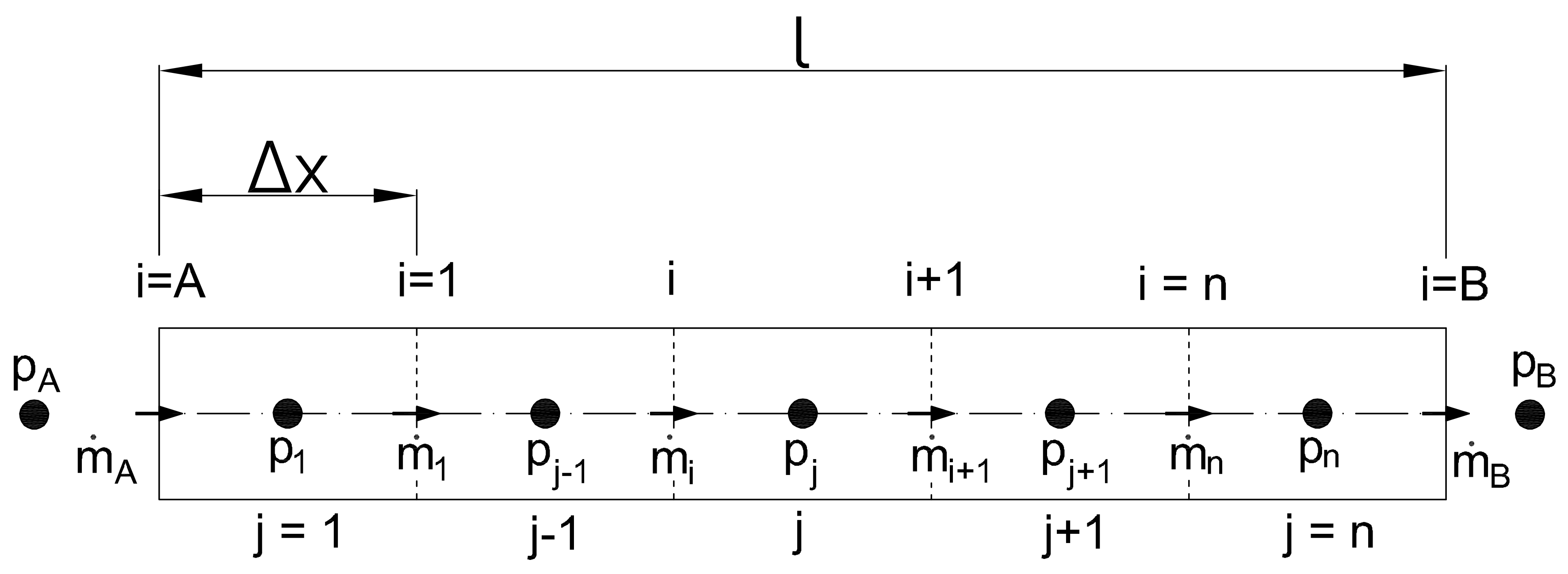
In order to illustrate the physical phenomena contributing to the generation of pneumatic noise, such as exhaust air expansion, air flow through tubes, and sound generation from monopole and quadrapol sources, a mathematical model was created using the methods described in [10,19,20]. Figure 1 shows a discretized scheme of a tube with the air flow from the source at point A to the outlet at point B. The tube of length l is divided into n control volumes, each long, where the observables for each control volumes are the mass flow and the pressure, with indices i and j, respectively.
Numerical meshes of the mass flow and the pressure are shifted relative to each other so that pressure is recorded at the midpoint of the control volume, for which index j is assigned, and mass flow at its edges, for which index i is assigned.
Using the method of line [19,20], we assume that every observable and parameter is calculated in every space point as being dependent on time only. A pneumatic line of length l is parted into n segments of length . Coordinate x is discretized by two staggered grids for the pressure and the mass flow separately, respectively, the j and i indexes. Therefore, control volumes for the pressure and the mass flow are shifted. For the pressure grid for index the following parameters are defined
- -
- position of pressure nodes:
- -
- pressure:
- -
- mid cross section of each control volume:
- -
- humid air density calculated on each control volume: Correction for comment 5 Reviewer 1. We unified format of formulas and figureswhere: air constant , vapour constant , temperature T, ambient pressure , relative humidity , saturation pressure for humid air temperature. For = 1 the product equals the pressure of vapor contained in the humid air . For the mass flow grid for the following parameters are defined
- -
- Position of mass flow nodes
- -
- Mass flow
- -
- Cross-section of each control volume edge
- -
- Speed of sound: Correction for comment 5 Reviewer 1. We unified format of formulas and figures
- -
- Air velocity: Correction for comment 5 Reviewer 1. We unified format of formulas and figures
2.1. The Dynamics of Air Expansion at the Boundaries
The process of air discharge from the chamber is associated with a change in mass over time, due to the mass through the channel at different pressures. Due to the speed of the exhaust air, expansion process and the small air flows, it was assumed that air expansion is adiabatic [21].
The mass flow between the volume under pressure and the volume under pressure is defined by Equation (11) [22,23]. If the pressure ratio for the left side of the tube , for , we have and , is lower than the air exhaust flow is sonic. On the other hand, if the pressure ratio on the right side , for , we obtained and , is lower than the air exhaust flow is also sonic. While the pressure ratio is greater than , the air exhaust flow is subsonic
Equation (11) is simultaneously valid for boundaries and . Index j takes the following values: , for and , for . Moreover, the scaling factor Z and factor caused by the non-ideal air mass flow due to the sharp-edged orifice [23] is formed as
2.2. Pneumatic Transmission Line Model
The 1-D pneumatic transmission line model (Figure 1) is given by way of a system of ordinary differential equations (ODE) based on the continuity equation and the equation of motion of air flow [21]
where pressure and mass flow are dependent on time t and coordinate x, calculated according to Figure 1, A is the pneumatic line cross-section, density of the moist air, dynamic viscosity and the pneumatic line diameter. The Darcy–Weisbach equation is used to model the friction phenomenon in air-flow through a pneumatic line [19]. The Darcy friction factor , included in the Darcy–Weisbach equation, is a function of Reynolds number , kinematic viscosity , tube diameter and tube roughness . However, as claimed in [24,25], the error in determining the Darcy friction factor for the compressible flow with the Mach number less than 0.6 () is not greater than 3 % and can be used successfully in such an application. In the case of air flows in a pneumatic, this condition is fulfilled [19]. The formulae proposed by [26] were used to determine the Darcy friction factor
2.3. Acoustic Model
Due to the mass flow, the impulse noise is mainly composed of monopole and quadrupole sources. The acoustic pressure i.e., the difference between the instantaneous pressure at a certain point in the disturbed medium and its average value under equilibrium conditions, from a monopole source at distance s from this source, is [10]
where is the outlet air flow at the end of the pneumatic line (see Figure 1 and Equation (11)).
Furthermore, the acoustic pressure from the quadrapole source at distance s from the pneumatic line end is [10]
where: proportional constant K = 8 × 10⁻⁶, exhaust line diameter , pressure at the end of the pneumatic line , ambient pressure (see Figure 1). Sound Pressure Levels (SPL) from the monopole and quadrapole sources [10] are
respectively, where the reference pressure = 20 Pa. Total Sound Pressure Level (SPL) [8] combined from the monopole and quadrapole source is
Depending on the mass flow velocity and frequency, one of the above-mentioned sources of noise may dominate. The complete acoustic model represents a practical tool to calculate the pneumatic noise generation from the expansion of exhaust air. The mathematical model was implemented in the MATLAB environment and the ODE system was solved using the Runge Kutty Felhberg procedure. The following assumptions were made for the mathematical model: air is treated as an ideal gas, the flow is isothermal and the flow velocity is less than 0.6 Ma, which allows for the application of the Darcy–Weisbach formula for air and, based on the 1-D flow model, the average air velocity in the tube profile is considered.
3. Experimental Setup
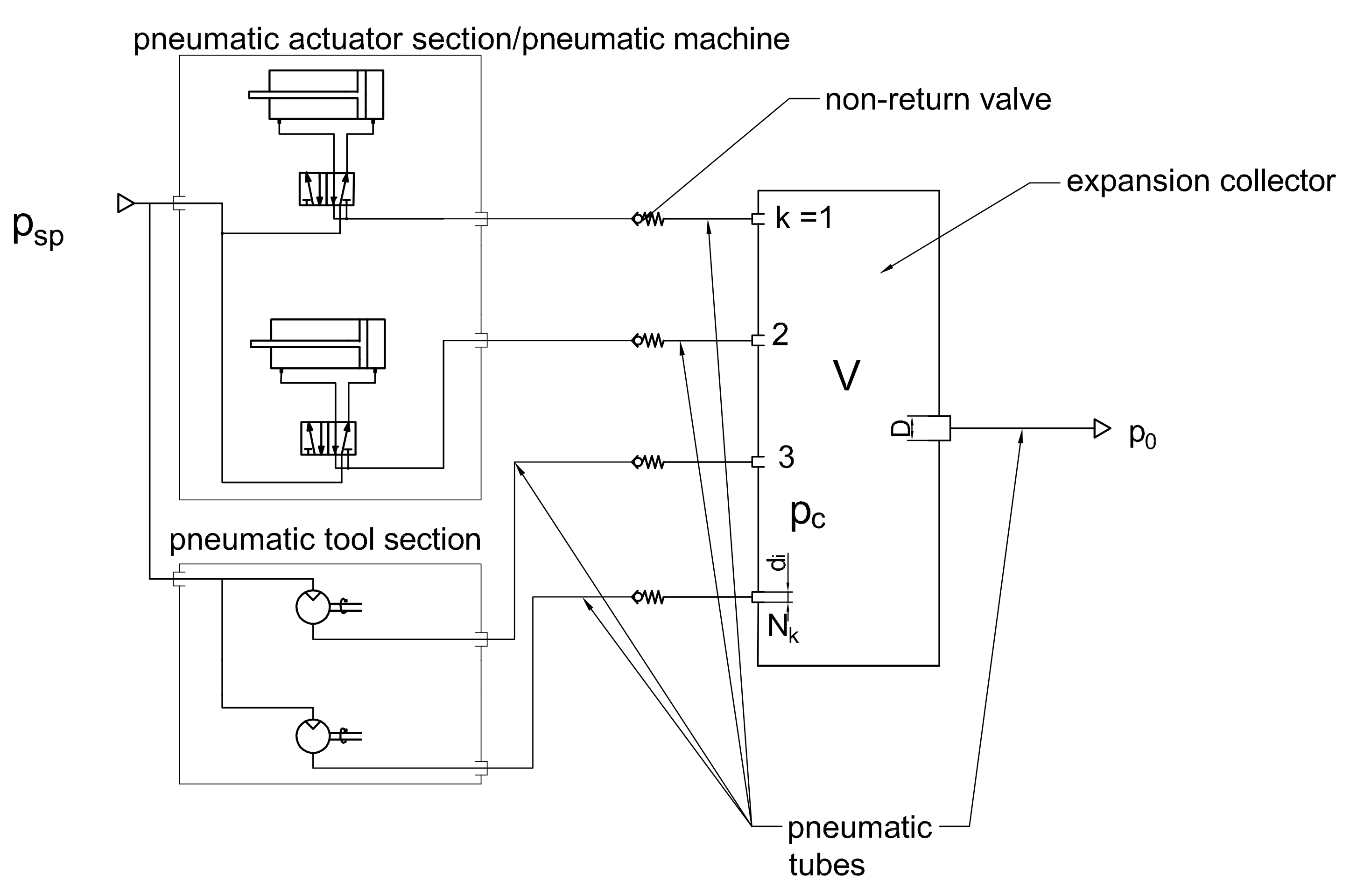
The idea of the expanded collecting (EC) system is to capture exhaust air from dispersed outlets of pneumatic tools and machines in production area and throw it outside the working environment(see Figure 2) [18].
The existing pneumatic mufflers mounted at the outlet of pneumatic tools and machines are replaced by the pneumatic tubes, with cross-section areas no smaller than the cross-sectional areas of the exhaust air outlets, and non-return valves. The other ends of the pneumatic tubes are connected to the expanded collector with a volume defined by the formula
where supply pressure , pressure in expansion collector , volume flow from pneumatic tool or machine , operating time , number of collector inlet and index of collector inlets k.Then, through one outlet pneumatic tube with the cross-sectional area, no smaller than the sum of the cross-sectional areas of the inlet pneumatic tubes to the expansion collector, the exhaust air is thrown outside the working environment; for example, outside the room, building, etc. Proper selection of the cross-sectional areas of the pneumatic tubes and the volume of the expanded collector is crucial in order not to disturb the operation of pneumatic tools and machines. The solution reduces the pneumatic noise generated during the dispersed expansion of the air through pneumatic mufflers. Then, the noise from part of or the entire production hall is collected in one place (expansion collector), which makes it easier to neutralize.
In order to determine the sound pressure level (SPL) to which the technical operator is exposed, two tests were performed in a partial isolated workshop adjacent to the office of the maintenance department and on window-fitting stand (Figure 3) Measurements of the sound pressure level were made using Svan 959 Class 1 sound-level meter by SVANTEK, with a preamplifier by SVANTEK, type SV12L and a microphone by G.R.A.S, type 40AE. Before the start of the measurements and after the completion of the measurements, the meter was calibrated using a Brüel & Kjær type 4231 calibrator. The measurements were made in the broadband range, taking into account the correction characteristics (A and Z). The sound spectrum in one-third octave bands and the following basic acoustic parameters were recorded
- -
- (dB)—the equivalent sound pressure level;
- -
- (dBA)—the equivalent A-weighted sound pressure levell
A hand-held pneumatic screwdriver SHINANO SI-1166-8A was used for both tests, whose parameters are presented in Table 1. The screwdriver was supplied with compressed air directly from the plant’s compressed air supply system, with an operating gauge pressure of approximately 8.5–9.0 bar.
The first test was to measure the noise level generated by a hand-held pneumatic screwdriver in a partial isolated workshop adjacent to the office of the maintenance department in order to reduce the impact of high acoustic background in the production hall (Figure 3a). The measurement was performed for the pneumatic screwdriver in three variants of its outlet, as shown in Figure 4.
The first variant, shown in Figure 4a, is a standard factory configuration of the hand-held pneumatic screwdriver with the outlet equipped with perforated pneumatic muffler in the form of air exhaust channels on the circumference of the inlet nozzle (photo in Figure 4a). Then, in variant 2, the outlet from the pneumatic screwdriver was modified to a separate outlet port, as shown in Figure 4b. In the last variant (Figure 4c), a pneumatic tube from the expanded collecting system was connected to the modified outlet port of the hand-held pneumatic screwdriver from variant 2. The pneumatic tube with an outlet diameter d = 12 mm and length l = 10 m was used, while the other end of it was placed outside the workshop. In all three variants, the in situ measurements were made at a distance of one meter from the screwdriver in a direction perpendicular to the direction of the air outlet.
Then, the test of the technical scale was performed on the production hall in the section of window fitting stands, Section 2, stand no. 1 (see Figure 5a).
Figure 5b shows an outline of the window-fitting stand, where noise level measurements took place. The technical operator has three pneumatic tools at his disposal: table pneumatic screwdriver, hand-held pneumatic drill and hand-held pneumatic screwdriver. During his work, he is exposed to noise coming directly from those three used devices, stands in the immediate vicinity in the subsection and the acoustic background of the entire plant. Moreover, the SPL measurements were carried out at the window-fitting stand equipped with the hand-held pneumatic screwdriver in two variants: standard factory configuration (with the pneumatic muffler) and with the expanded collecting system. The EC system was used by the attaching pneumatic tube (d = 12 mm, l = 8 m) to the outlet port of the hand-held pneumatic screwdriver and connected to the expanded collector with volume V = 15 dm3. The pneumatic tube from the expanded collector was placed out of the subsection, according to the outline shown in Figure 5c. The noise level measurement was carried out on the basis of standard PN-EN ISO 9612:2011.
4. Results
4.1. Mathematical Model Validation
Therefore, to confirm the usefulness of the mathematical model, this should be validated. For this purpose, the results of a computer simulation in the MATLAB of the model of the exhaust air flow through a pneumatic tube, given by Equation (11), were compared with experimental data from the literature [19] (Figure 6). Next, a full validation of the mathematical model of air expansion, tube airflow, and sound generation was performed with the results of our own experimental results. The validation of the transmission line model (see Equation (11)) was performed by comparing the pressure values at the beginning of the tube and at the end (see Figure 1). For this purpose, the conditions of the experiment presented in [19] were used. A pneumatic tube of length l = 5 m and inner diameter d = 5.7 mm was connected to a compressed air supply of gauge pressure = 6 bar. The other end of the tube was connected to a closed air tank of volume 0.1 l.
High compliance of the mathematical model with experimental data [19] was obtained as a result. The maximum error between the results of the simulation and the experiment is 4.5% for pressure and 3.6% for pressure . The non-linear nature of the air flow may be observed on the pressure curve . This results from the propagation of the shock wave due to the discontinuity at the source–tube interface at the initial moment through the sharp-edged orifice.
Then, the entire mathematical model was validated, taking the formulas responsible for sound generation into account, as in Equations (18)–(21), with the data obtained in the experimental measurements. The experiment on the laboratory-scale was carried out in the workshop, with background noise levels of 49 dB. The measurements consisted of measuring the sound generated by the hand-held pneumatic screwdriver, with parameters included in Table 1, with a free air outflow through the outlet (according to Figure 4b). The sound-level pressure was measured during idle operation of the tool for 20 s at a distance of 1 m. For the first 10 s, the tool worked in the intermittent mode with a interval of 2 s and duty cycle 50%, while the remaining time was in the continuous mode. The resulting time domain signal was then transformed into the frequency domain using the Fast Fourier Transformate (FFT) and 1/3 octave-band filter. As the experimental results are included in the range of 1/3 octave frequencies band from 100 Hz to 16 kHz, the results from the computer simulation are also limited to the same frequency range. Then, the signal processed in this way was compared with the sound pressure levels obtained in the experimental measurements using the Z filter (see Section 3). The Figure 7 shows a comparison of the pneumatic noise generated by the free flow of air through the outlet.
A high convergence of the computer simulation data values with the measurement data is obtained for the one-third octave frequency bands from 1 to 16 kHz, for which most of the differences ranged from 1 to 2.4 dB. The maximum difference was 2.9 dB for the frequency 1600 Hz. Similar values of the computer simulation data, juxtaposed with the measurement data, were also obtained for frequencies 100 and 200 Hz. In the frequency range from 315 to 630 Hz, the model begins to diverge from the measured data. The discrepancy of the mathematical model for low frequencies may result from unidentified acoustic sources in the real system and not the smooth combination of two sound-generation formulas.
4.2. Industrial Test
The developed theoretical models were verified for two operating modes of the device: for an idle mode in the workshop adjacent to the office of the maintenance department, and for standard operations on the window-fitting stand in the production hall. The in situ measurements were carried out to determine the background sound-pressure level and the sound-pressure level for a screwdriver damped with a factory pneumatic muffler and a tube collector. The background noise level in the office of the maintenance department was 49 dBA (Table 2).
A-weighted equivalent sound-pressure level of the idle device was determined by twenty-second measurements at a distance of 1 meter. As already mentioned, two cases of screwdriver operation were considered: standard factory configuration (see Figure 4a) and that with an expansion collecting system (see Figure 4c). A-weighted equivalent sound level for the first case was 96 dBA and for the second case it was 78 dB (Figure 8).
It is worth noting that the distance between the measured signals ( of screwdriver operation and the background level) is 47 and 29 dBA, respectively. Such a large difference between the measured acoustic signals makes it possible to observe the actual decrease in the noise level generated by the screwdriver. The reduction of the noise level of the screwdriver was about 18 dBA, i.e., the acoustic pressure at a distance of 1 meter from the device decreased by eight times. This means that the modification of pneumatic devices at all positions in the production hall, consisting of the expanded collecting system, should significantly reduce the overall noise level at workplaces.
The second part of the experimental research was conducted at the window-fitting work station in the production hall. In the first stage, the background sound-pressure level measurement was performed over short intervals between production cycles at the test stand. The average SPL in the production hall was calculated based on three measurements, and was 77.9 dBA (Table 3). Such a high level of acoustic background results from the fact that normal work was carried out on the neighbouring stands during the in situ tests.
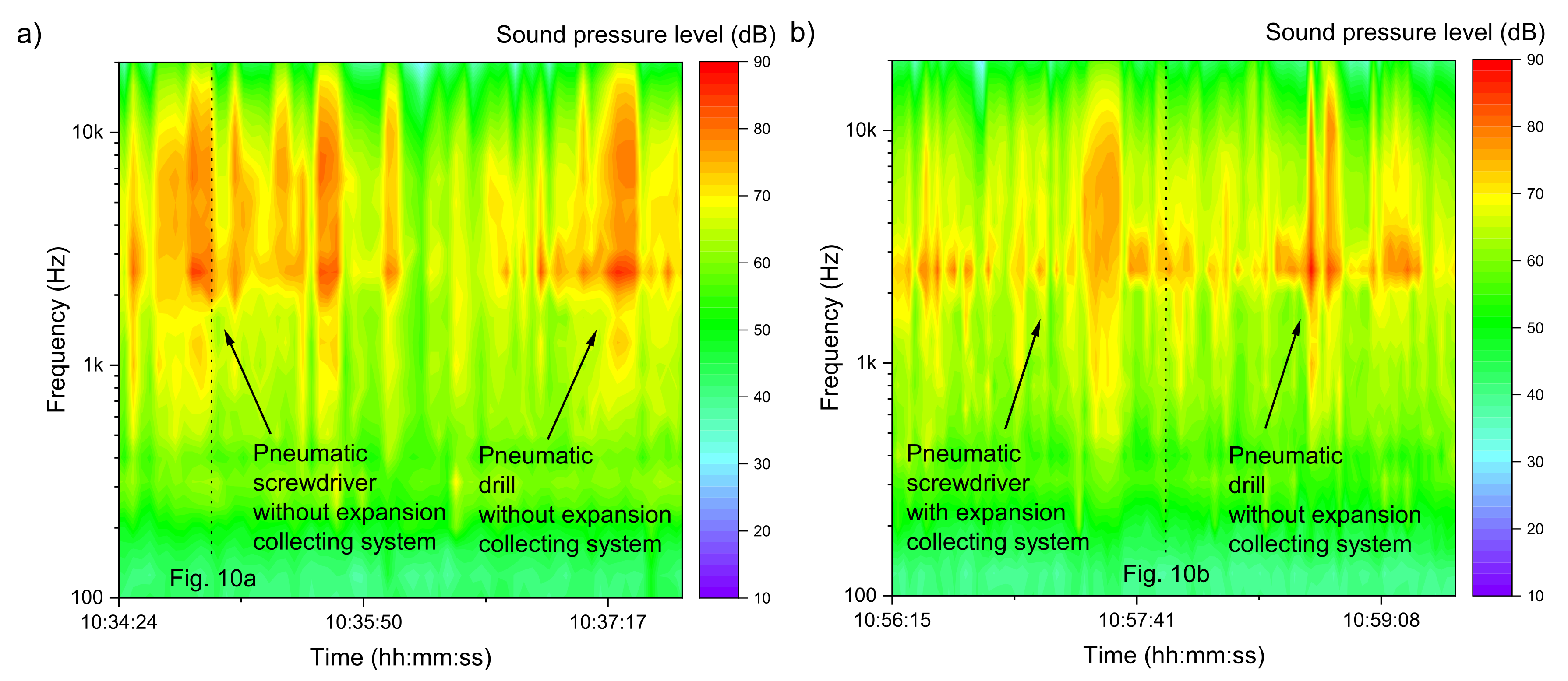
Measurements were made for production cycles lasting from 3 to 5 min. Two cases of screwdriver operation were considered: at standard factory configuration(with pneumatic muffler) and with expanded collecting system. The equivalent sound level for the first production cycle (see Figure 5b) is 82.8 dBA, and (see Figure 5c) is 81.1 dB for the second production cycle. The time-frequency characteristics of the A-weighted sound-pressure level of one production cycle of the window fitting are shown in Figure 9.
A comparison between Figure 9a and Figure 9b shows that the highest sound levels are recorded for frequencies above 1 kHz, with the maximum values occurring for one-third octave bands with center frequencies from 2.5 to 12 kHz. In that frequency range, the greatest decrease in the sound-pressure level can also be observed after the use of the expanded collecting system. On the spectrogram shown in Figure 9b, we can also observe an example from a fragment of the process for which no significant decrease in the noise level was noticed (just before 10:59). This is the moment when an unmuted pneumatic drill works—the new solution was not used.
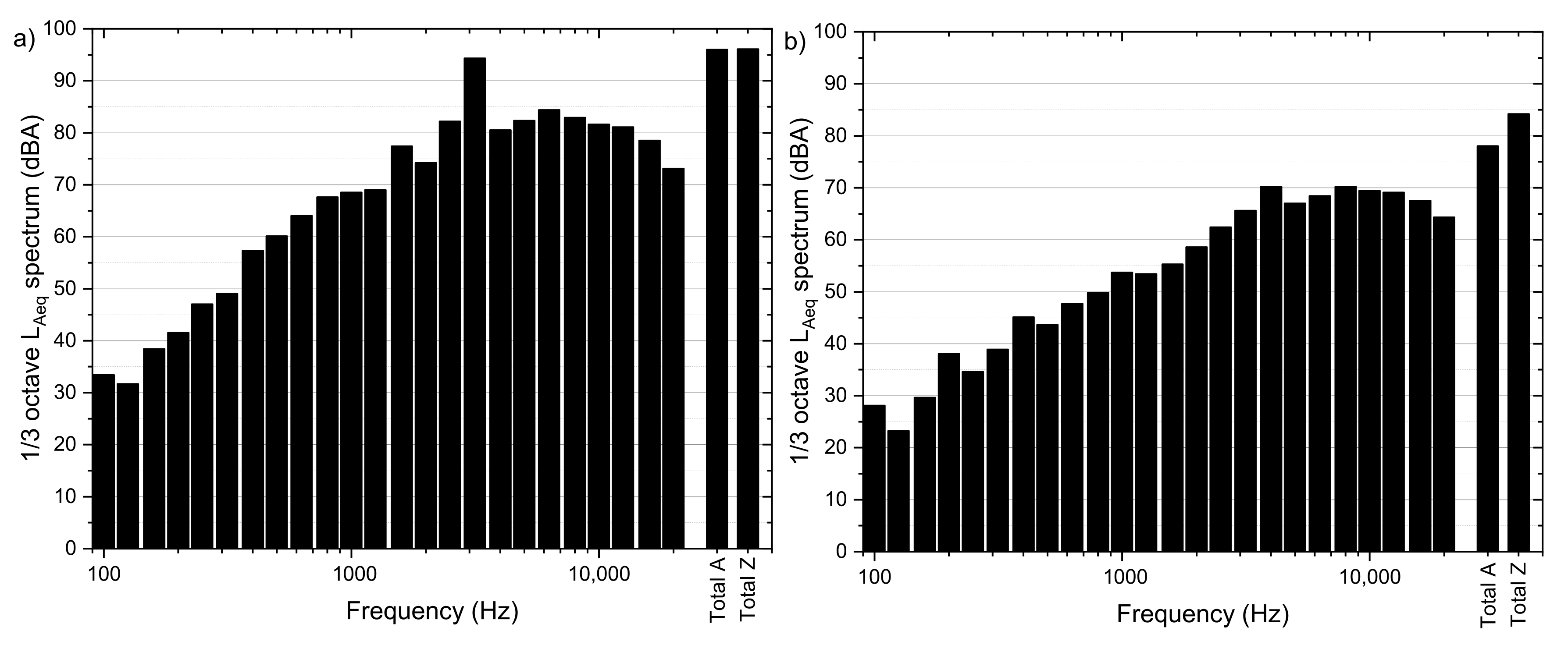
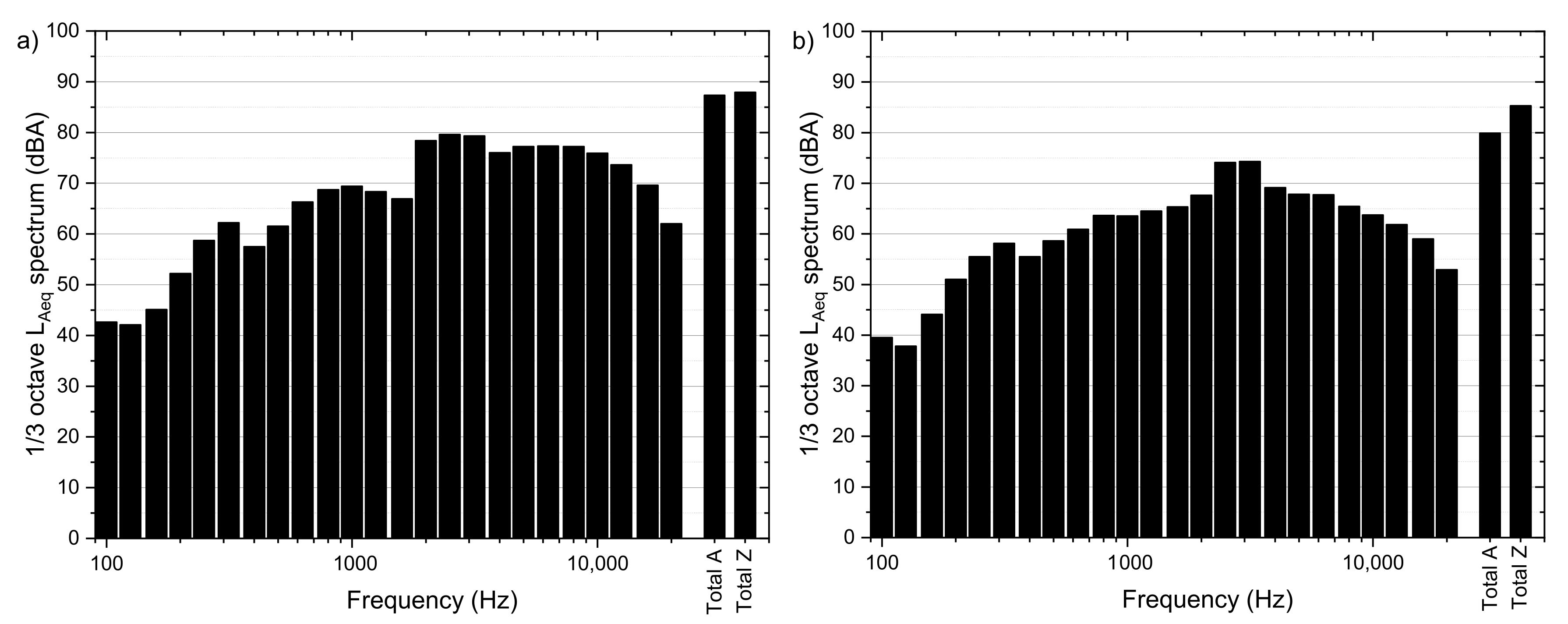
The 1/3 octave band equivalents of A-weighted sound-pressure level spectrum of the noise of a pneumatic device standard factory configuration and with expansion collecting system are shown on Figure 10, respectively.
Sound spectrum (Figure 10b) shows a significant decrease in the sound pressure level, especially for high frequencies. Based on the analysis of the presented measurement results, it can be seen that the total A SPL value for the situation with the expanded collecting system is 79.9 dBA, while at standard factory configuration(with pneumatic muffler), it is 87.3 dBA. After the expanded collecting system was used, the noise generated on the stand while the operator used a hand-held pneumatic screwdriver was almost reduced to the background noise level in the production hall. Therefore, it was not possible to achieve a lower value.
The results of the tests showed that the noise level at the workplace is very high, almost 90 dBA, despite the use of factory-made pneumatic mufflers. The measurements confirmed the high potential of the proposed solution, which reduces noise level from pneumatic tools and machines in production hall. However, due to the high acoustic background of the hall and the noise generated directly from the neighboring stands, the average noise level at the stand was reduced from 82.8 to 81.1 dBA. It is worth noting that a 1 dBA change in noise level is just a noticeable difference. Therefore, the expanded collection system should be applied to at least one subsection of window-fitting stands to achieve a significant noticeable difference.
Figure 11 shows the proposed design of the expanded collecting system for one subsection in the production hall. At each stand, there is a local expansion collector to which all tools are connected through a pneumatic tube. The local expansion collector is then linked to the main expansion collector. It should be noted that, at a given time, only one pneumatic tool is used at a given stand; therefore, the diameters of the tubes to and from local collectors may have the same internal diameter—in this case, d = 12 mm. According to the Equation (22), the minimum volumes of local and main collectors are: 15 dm3 and 60 dm3, respectively. As such, the expanded collecting system will remove the pneumatic noise in the showed subsection, leaving only noise coming from other sections of the production hall.
5. Conclusions
The article presents a new, consistent method of reducing pneumatic noise from machines and tools in production halls. The expanded collecting system captures exhaust air from pneumatic tools and machines outlets scattered throughout the production hall in one main collector. Then, the collected exhaust air in one place can be neutralized or thrown outside the production hall and reducing the noise generated as a result of air expansion in the working environment.This solution has been tested on the industrial scale.
To illustrate how our approach works, we built a mathematical model of the entire process of sound generation during the exhaust air expansion. The pneumatic line model is necessary for assessment of the dynamics of expanding air. We obtain changes in mass flow and pressure over time and at the end of pipes. Such observables are sensitive to the line topology (i.e., the diameter and length of pipes) and variables of initial conditions, such as, for example, pressure in expansion collector. Finally, through the use the acoustic theory and observables determined above, one may assess the noise level over time.Then, the model is validated with the measurement results of a pneumatic screwdriver without a muffler. The analytical results show a very good correlation with the measurement data at a high-frequency sound, from 1 to 16 kHz, and also for low frequencies of 100 and 200 Hz. The discrepancy of the mathematical model for low frequencies from 200 Hz to 1 kHz may result from unidentified acoustic sources in the real system, and the not-smooth combination of two sound generation formulas.
Then, measurement of the noise reduction in the hand-held pneumatic screwdriver in a partially insulated workshop was carried out. The results showed an approximately 8-fold reduction in the SPL (from 96 do 78 dBA) of the pneumatic screwdriver with the expanded collecting system compared to a standard configuration with a factory muffler. The expanded collecting system is able to reduce noise by from 1.5 to even 4 times compared to current solutions, which are capable of reducing pneumatic noise to 82–90 dBA. It should be emphasized that the tests were conducted in a separate workshop, but still located in the production hall.
Then, the industrial test was carried out in the production hall (see Figure 5) at a very high background noise of 77.9 dBA, caused by the large number of machines and pneumatic tools. Moreover, at one window-fitting stand, the operator is exposed to an average noise level of 82.8 dBA, temporarily exceeding 91.8 dBA. Thus, the noise level at the window-fitting stand exceeded 80 dBA, which, according to the Occupational Safety and Health Administration, is considered dangerous to human health. On the other hand, when the operator used a pneumatic screwdriver with the expanded collecting system, the noise level was reduced to 79.9 dBA, which was almost the background noise level. Because it is impossible to separate the background noise from the stand in the production hall, further noise reduction is presented. It would be necessary to apply the solution to subsequent tools and stands, as shown in Figure 11, to obtained further noise reduction.Due to the measured, very high level of acoustic background in the hall, of 77.9 dBA, noise measurements were carried out on one window-fitting stand. The aim was to apply the EC system to one pneumatic screwdriver and determine the effect on noise generated at the stand. The conducted noise measurements of the hand-held pneumatic screwdriver in an industrial environment confirm the possibility of reducing the pneumatic noise at a workplace on a full technical scale. When the expansion-collecting system is applied to the screwdriver, the measured SPL decreases from 87 to 80 dBA. It should be noted that the EC system was installed for only one pneumatic tool, so the implementation of the proposed system for the entire subsection would radically change the conditions of a working environment. Further, the EC system can also be used for other subsections or for other pneumatic machines in production hall.
Author Contributions
Conceptualization, J.S.L. and J.W.; methodology, D.C., J.S.L. and J.W.; software, D.G.; validation, D.G. and D.C.; formal analysis, D.G., D.C., J.S.L. and J.W.; investigation, D.G. and D.C.; resources, D.G. and D.C.; writing—original draft preparation, D.G. and D.C.; writing—review and editing, J.S.L. and J.W.; visualization, D.G. All authors have read and agreed to the published version of the manuscript.
Funding
This research was funded by research subvention supported by the Polish Ministry of Science and Higher Education grant number 16.16.210.476 and 16.16.130.942.
Institutional Review Board Statement
Not applicable.
Informed Consent Statement
Not applicable.
Data Availability Statement
Not applicable.
Acknowledgments
This research was supported in part by PLGrid Infrastructure.
Conflicts of Interest
The authors declare no conflict of interest.
References
- Dindorf, R.; Wos, P.; Pawelec, K. Automatic device for indirect measurement of leakage flow rate in compressed air pipeline. IOP Conf. Ser. Mater. Sci. Eng. 2017, 233, 159–170. [Google Scholar] [CrossRef] [Green Version]
- Dindorf, R.; Takosoglu, J.; Wos, P. Development of Pneumatic Control Systems, m89 ed.; Wydawnictwo Politechniki Świȩtokrzyskiej: Kielce, Poland, 2017. [Google Scholar]
- Li, J.; Zhao, S. Optimization of valve opening process for the suppression of impulse exhaust noise. J. Sound Vib. 2017, 389, 24–40. [Google Scholar] [CrossRef]
- Raghunathan, S.; Kim, H.D.; Setoguchi, T. Impulse noise and its control. Prog. Aerosp. Sci. 1998, 34, 1–44. [Google Scholar] [CrossRef]
- Li, J.; Zhao, S.; Ishihara, K. Study on acoustical properties of sintered bronze porous material for transient exhaust noise of pneumatic system. J. Sound Vib. 2013, 332, 2721–2734. [Google Scholar] [CrossRef]
- Lighthill, M.J. On sound generated aerodynamically I. General theory. Proc. R. Soc. Lond. Ser. A. Math. Phys. Sci. 1952, 211, 564–587. [Google Scholar] [CrossRef]
- Lighthill, M.J. On sound generated aerodynamically II. Turbulence as a source of sound. Proc. R. Soc. Lond. Ser. A Math. Phys. Sci. 1954, 222, 1–32. [Google Scholar] [CrossRef]
- Shi, H.; Zhao, S. Prediction of radiation characteristic of intermittent exhaust noise generated via pneumatic value. Noise Control Eng. J. 2009, 57, 157–168. [Google Scholar] [CrossRef]
- Ivanov, Y.V. Reducing the aerodynamic noise of pneumatic nozzles in the pneumatic mechanisms of forges and presses. Metallurgist 2011, 55, 139–142. [Google Scholar] [CrossRef]
- Zhao, S.; Wang, J.; Wang, J.; He, Y. Expansion-chamber muffler for impulse noise of pneumatic frictional clutch and brake in mechanical presses. Appl. Acoust. 2006, 67, 580–594. [Google Scholar] [CrossRef]
- Official Journal of the European Union. Directive 2003/10/EC of the European Parliament and of Council of 6 February 2003 on the Minimum Health and Safety Requirements Regarding the Exposure of Workers to the Risks Arising from Physical Agents (Noise); European Union: Luxembourg, 2003; pp. 38–44. [Google Scholar]
- ISO 1999:2013. Acoustics-Estimation of Noise-Induced Hearing Loss; International Organization for Standardization: Geneva, Switzerland, 2006. [Google Scholar]
- Czopek, D.; Korbiel, T.; Kukulski, B.; Małecki, P.; Pawlik, P.; Stȩpień, B.; Wszołek, T.; Wszołek, W. New Methods of Signal Processing in the Selected Vibroacoustics Problems; Monograph AGH University of Science and Technology: Cracow, Poland, 2016. [Google Scholar]
- Kozupa, M.; Wiciak, J. Comparison of passive and active methods for minimization of sound radiation by vibrating clamped plate. Acta Phys. Pol. A 2011, 119, 1013–1017. [Google Scholar] [CrossRef]
- Kozień, M.S.; Wiciak, J. Reduction of structural noise inside crane cage by piezoelectric actuators—FEM simulation. Arch. Acoust. 2008, 33, 643–652. [Google Scholar] [CrossRef]
- Li, J.; Zhao, S.; Ishihara, K.; Shi, H. Numerical and Experimental Studies on Aerodynamic Characteristics of Pneumatic Exhaust with Perforated Panel Muffler. Adv. Mater. Res. 2011, 294, 2125–2129. [Google Scholar] [CrossRef]
- Daggerhart, J.A.; Berger, E. Evaluation of Mufflers To Reduce Punch Press Air Exhaust Noise. Noise Control Eng. 1975, 4, 120–123. [Google Scholar] [CrossRef]
- Leszczynski, J.S.; Grybos, D.; Borek, M. Układ Do Kolektorowania Powietrza Odpadowego z Sekcji Instalacji Pneumatycznej; PL432516A1; Polish Patent Office: Warsaw, Poland, 2020.
- Krichel, S.V.; Sawodny, O. Non-linear friction modelling and simulation of long pneumatic transmission lines. Math. Comput. Model. Dyn. Syst. 2014, 20, 23–44. [Google Scholar] [CrossRef]
- Patankar, S.V. Numerical Heat Transfer and Fluid Flow; Hemisphere Publishing Corporation: New York, NY, USA, 1980. [Google Scholar]
- Beater, P. Pneumatic Drives; Springer: Berlin/Heidelberg, Germany, 2007; p. 319. [Google Scholar] [CrossRef]
- Cengel, Y.A.; Boles, M.A. Thermodynamics. An Engineering Approach, 5th ed.; Mc.Graw–Hill Education: New York, NY, USA, 2015. [Google Scholar]
- Leszczynski, J.S.; Grybos, D. Compensation for the complexity and over-scaling in industrial pneumatic systems by the accumulation and reuse of exhaust air. Appl. Energy 2019, 239, 1130–1141. [Google Scholar] [CrossRef]
- Idelchik, I.E. Handbook of Hydraulic Resistance, 2nd Edition. J. Press. Vessel. Technol. 1987, 109, 260–261. [Google Scholar] [CrossRef] [Green Version]
- Voronin, S.F. Effect of contraction on the friction coefficient in a turbulent gas flow. Inzh. Fiz. Z. 1959, 23, 81–85. [Google Scholar]
- Bellos, V.; Nalbantis, I.; Tsakiris, G. Friction Modeling of Flood Flow Simulations. J. Hydraul. Eng. 2018, 144, 04018073. [Google Scholar] [CrossRef] [Green Version]
Figure 1.
1-D pneumatic transmission line model [19].
Figure 1.
1-D pneumatic transmission line model [19].

Figure 2.
Outline of the expanded collecting system.

Figure 3.
Schematic diagram of the measurement procedure for an acoustic test. Measurement was carried out for the following sound sources: * The hand-held pneumatic screwdriver with standard factory configuration (with muffler), with modified outlet port and with the expanded collecting system. ** The hand-held pneumatic screwdriver with standard factory configuration (with muffler) and with the expanded collecting system.

Figure 4.
The hand-held pneumatic screwdriver used for measurements: (a) at standard factory configuration(with pneumatic muffler); (b) with self-modified outlet port (c) with the expanded collecting system.
Figure 4.
The hand-held pneumatic screwdriver used for measurements: (a) at standard factory configuration(with pneumatic muffler); (b) with self-modified outlet port (c) with the expanded collecting system.

Figure 5.
The outline of: (a) general production hall; (b) the window fitting stand no 1, Section 2; (c) the window-fitting stand no 1, Section 2 with the expanded collecting system.

Figure 6.
Validation of the mathematical model of the pneumatic transmission line with experimental data included in [19].
Figure 6.
Validation of the mathematical model of the pneumatic transmission line with experimental data included in [19].

Figure 7.
Comparison of the 1/3 octave band equivalent of A-weighted sound-pressure-level average spectrum of the noise of a hand-held pneumatic screwdriver obtained from the computer simulation and the experiment.
Figure 7.
Comparison of the 1/3 octave band equivalent of A-weighted sound-pressure-level average spectrum of the noise of a hand-held pneumatic screwdriver obtained from the computer simulation and the experiment.

Figure 8.
The 1/3 octave band equivalent of A-weighted sound-pressure level average spectrum of the noise of a hand-held pneumatic screwdriver: (a) at standard factory configuration(with pneumatic muffler); (b) with the expanded collecting system.
Figure 8.
The 1/3 octave band equivalent of A-weighted sound-pressure level average spectrum of the noise of a hand-held pneumatic screwdriver: (a) at standard factory configuration(with pneumatic muffler); (b) with the expanded collecting system.

Figure 9.
Spectrogram of a sample window fitting cycle: (a) at standard factory configuration(with pneumatic muffler); (b) with the expanded collecting system.
Figure 9.
Spectrogram of a sample window fitting cycle: (a) at standard factory configuration(with pneumatic muffler); (b) with the expanded collecting system.

Figure 10.
The 1/3 octave band equivalent of A-weighted sound pressure level spectrum of the noise of a hand–held pneumatic screwdriver: (a) at standard factory configuration(with pneumatic muffler); (b) with expanded collecting system.
Figure 10.
The 1/3 octave band equivalent of A-weighted sound pressure level spectrum of the noise of a hand–held pneumatic screwdriver: (a) at standard factory configuration(with pneumatic muffler); (b) with expanded collecting system.

Figure 11.
Proposed modification of the subsection no 2 of window-fitting stands by applied the EC system.
Figure 11.
Proposed modification of the subsection no 2 of window-fitting stands by applied the EC system.


Table 1.
Technical parameters of the hand-held pneumatic screwdriver SHINANO SI-1166-8A.
| Parameter | Value |
|---|---|
| Maximum rotational speed | 2000 rpm |
| Maximum torque | 9 Nm |
| Supply gauge pressure | 8.5–9.0 bar |
| Air volume flow | 200 dm3/min |
| Supply inlet diameter | 1/4’ |
| Exhaust outlet diameter | 3/8’ |
Table 2.
The acoustic background level of the production hall.
| No. of Measurement | (dBA) | (dB) |
|---|---|---|
| 1 | 49.3 | 80.9 |
| 2 | 48.7 | 80.1 |
| 3 | 49.9 | 81.4 |
Table 3.
The acoustic background level of the production hall.
| No. of Measurement | (dBA) | (dB) |
|---|---|---|
| 1 | 78.0 | 80.4 |
| 2 | 78.6 | 80.8 |
| 3 | 77.2 | 79.6 |
Publisher’s Note: MDPI stays neutral with regard to jurisdictional claims in published maps and institutional affiliations. |
© 2021 by the authors. Licensee MDPI, Basel, Switzerland. This article is an open access article distributed under the terms and conditions of the Creative Commons Attribution (CC BY) license (http://creativecommons.org/licenses/by/4.0/).
Share and Cite
MDPI and ACS Style
Gryboś, D.; Leszczyński, J.S.; Czopek, D.; Wiciak, J. Exhaust Noise Reduction by Application of Expanded Collecting System in Pneumatic Tools and Machines. Energies 2021, 14, 1592. https://doi.org/10.3390/en14061592
AMA Style
Gryboś D, Leszczyński JS, Czopek D, Wiciak J. Exhaust Noise Reduction by Application of Expanded Collecting System in Pneumatic Tools and Machines. Energies. 2021; 14(6):1592. https://doi.org/10.3390/en14061592
Chicago/Turabian StyleGryboś, Dominik, Jacek S. Leszczyński, Dorota Czopek, and Jerzy Wiciak. 2021. "Exhaust Noise Reduction by Application of Expanded Collecting System in Pneumatic Tools and Machines" Energies 14, no. 6: 1592. https://doi.org/10.3390/en14061592
Note that from the first issue of 2016, this journal uses article numbers instead of page numbers. See further details here.