
Transient System Model for the Analysis of Structural Dynamic Interactions of Electric Drivetrains


Institute of Electrical Machines (IEM), RWTH Aachen University, Schinkelstrasse 4, 52062 Aachen, Germany
*
Author to whom correspondence should be addressed.
Energies 2021, 14(4), 1108; https://doi.org/10.3390/en14041108
Submission received: 19 January 2021
/
Revised: 12 February 2021
/
Accepted: 13 February 2021
/
Published: 19 February 2021
(This article belongs to the Special Issue Design and Application of Electrical Machines)
Abstract
:In electric drivetrains, the traction machines are often coupled to a gear transmission. For the noise and vibration analysis of such systems, linearised system models in the frequency domain are commonly used. In this paper, a system approach in the time domain is introduced, which gives the advantage of analysing the transient behaviour of an electric drivetrain. The focus in this paper is on the dynamic gear model. Finally, the modelling approach is applied to an exemplary drivetrain, and the results are discussed.
1. Introduction
For the consideration of local loads and acoustics in electric vehicle drivetrains, it is not sufficient to consider the components, such as the motor and gearbox, separately. Due to the interactions of the individual components on the system level, structural dynamic load peaks can occur in combination with the natural oscillation behaviour. Furthermore, the natural frequencies of the coupled system can change when compared to a separate analysis of the components. Consequently, a system approach is essential for mechanical load and noise, vibration, and harshness (NVH) analyses of such systems.
In recent studies, system models for NVH analysis have been frequently discussed, e.g., in [1,2,3]. Due to the complexity of such system models, simplifications are usually made. In [1], a linearised system approach around a particular operating point was presented in the frequency domain. The electromagnetic forces of a machine were calculated using analytic equations, and the gear excitations were modelled by a load-dependent transmission error formulation [1]. The system model described in [3] used an interpolation approach in the electromagnetic force calculation to reduce the model size. By using this model, a stationary linear interpolation of the resulting force harmonics between different rotational speeds was performed, which was then mapped to a structural dynamic finite element model (FEM) in the frequency domain. In [2], a system model was introduced, where an electromagnetic force model was coupled in the frequency domain to an elastic multi-body simulation (MBS) of a drivetrain. The MBS was solved in the time domain, thus allowing, for instance, the modelling of the non-linear gear dynamics and non-linear bearing characteristics.
The purpose of the models described above is an efficient noise prediction and vibration analysis of the drivetrain. However, possible interactions due to the coupling in the frequency domain of the electric machine with the mechanical system are neglected. In all model descriptions, the feedback of the structural dynamics to the electrical machine and its control is not considered.
In this paper, a system model in the time domain is proposed, which allows the analysis of not only the steady-state operating points, but also transient load changes, which can occur, e.g., in situations of driving a vehicle. Therefore, the transient behaviour of an electric machine with an electrical supply system and digital control is modelled using an extended two-axis (dq) model according to [4]. This approach considers, for instance, slotting effects, non-ideal sinusoidal currents due to power electronics and digital control, and non-linearities of the electric machines. For transmission gears, different excitation mechanisms, such as parametric, impulse, and geometric excitations, are described in the literature [5,6]. The models for describing those mechanisms’ operational point dependence yield non-linear differential equations [5]. The suggested system model in the time domain allows a consideration of these effects without any operating point linearisation, and therefore, the dynamic gear mesh interaction with the electric machine can be analysed.
The paper is structured as follows. First, a general overview of structural dynamic modelling approaches is given and a particular approach is chosen. In the second step, the excitation mechanisms of transmission gears are summarised and a dynamic gear model is selected. Then, the transient electric machine model used is briefly described. Finally, the modelling domains are coupled to a system model, which is then applied to an exemplary drivetrain, and the results are discussed.
2. Modelling the Structural Dynamics of Electric Drivetrains
The structural dynamic behaviour of drivetrains can be described with various mathematical models. According to [7], these models can be divided into their typical fields of application, as shown in Figure 1. The classification criteria are the system expansion, the complexity, and the frequency range.
For simple systems consisting of basic geometries, the component loads and vibrations can be described with analytical formulas, independently of the frequency range and the system extension. For more complicated geometries, these analytical formulas are not available.
In the lower-frequency range, simulations with multi-body systems (MBSs) offer the opportunity to analyse the vibrational behaviour of large and complicated systems. Here, individual components of the system are modelled by rigid bodies that can be linked with each other and the environment using so-called joint and force elements. Information is obtained about the joint and coupling forces as well as the motion quantities of the individual bodies. For higher frequencies, the assumption that bodies behave rigidly is no longer permissible, since the elastic deformation and the inherent behaviour of the individual bodies are essential.
The methods of flexible multi-body systems extend the valid frequency range of MBSs by considering these elastic deformations of individual bodies [8]. In order to map all of the elastic properties of the system, the finite element method (FEM) is used.
The number of degrees of freedom in the FEM is larger compared to MBSs, which leads to a higher computational effort and limits the applicability with regard to the system size [7]. If one is only interested in the acoustic radiation behaviour of a structure, the model of the boundary element theory (BEM) offers an efficient approach.
In the high-frequency range, the mode density increases, i.e., the number of natural oscillations per frequency interval, which makes the calculation of the individual natural oscillations increasingly difficult [7]. Statistical energy analysis (SEA) is an approach for efficiently generating statements about the structural dynamic behaviour in this area. For use in a system model that considers the structural dynamic interactions, in this paper, the multi-body system approach is chosen. As described later, it can model the non-linearities of a dynamic gear transmission within a force element. The relatively low number of degrees of freedom and, consequently, the lower computational effort allow an analysis and coupling in the time domain. This makes the method suitable for complex systems, such as electric drivetrains.
2.1. Gear Excitations
The dynamic forces in gearboxes that lead to vibrations are decisively determined by the tooth engagement of the gears. According to [5], excitation mechanisms in gears can be divided according to their excitation characteristics into the groups of parameter excitation, impulse excitation, and geometric excitation.
The parameter excitation model describes the force that arises through temporal changes in the system parameters for damping and stiffness. Such changes are mainly caused by the stiffness of the teeth, which depends on the angle of engagement.
According to [5], under certain conditions and under load, the meshing teeth can come in contact with the next unloaded tooth, resulting in an impulsive force. Furthermore, it has been pointed out that these non-ideal contact conditions during meshing can cause tooth flank damage during operation and should, therefore, not occur if a gear unit is carefully designed [5].
The geometric excitation model describes the force when rolling on a surface that is not ideally flat. If a simple single-mass oscillator is considered, this excitation describes a time-varying path at the base of an oscillator, through which a force is generated. In gear meshing, this results from manufacturing deviations and tooth flank modifications when the involute is rolled off [5].
When considering a gearbox under load, the geometrical excitation can be neglected when compared to the parameter excitation [5]. In addition to the excitation mechanisms presented, the authors of [5] described the frictional force excitation and the excitation due to tilting moments. These can be modelled as additional force excitations. The frictional force excitation in tooth contact has a significantly lower amplitude than the normal tooth force due to the friction coefficient and will, therefore, not be regarded in this paper. The tilting moments are automatically considered if the tooth contact is modelled by a three-dimensional simulation model with all six degrees of freedom [5].
Due to the circumstances described above, the parameter excitation is identified as the main vibration source of a gear under load and is, therefore, considered in more detail in the next section.
2.2. Dynamic Gear Transmission
In order to model the vibration behaviour and the excitations of a gearbox, various model approaches have been described in the literature [5,6]. In [6], a simple torsional vibration model of an unbounded cylindrical gear pair with the two rotational angles of the gear wheels as the degrees of freedom, and , was described. This model is shown in Figure 2. The parameter excitation of the gear mesh is represented by the force elements of the variable spring and damper , which are oriented in the direction of the line of contact. The geometric excitation can be modelled using a path source .
Using the moment of inertia J around the individual rotational axis of the gear wheels and the base circle , the equation of motion for the first gear wheel can be set up [6]:
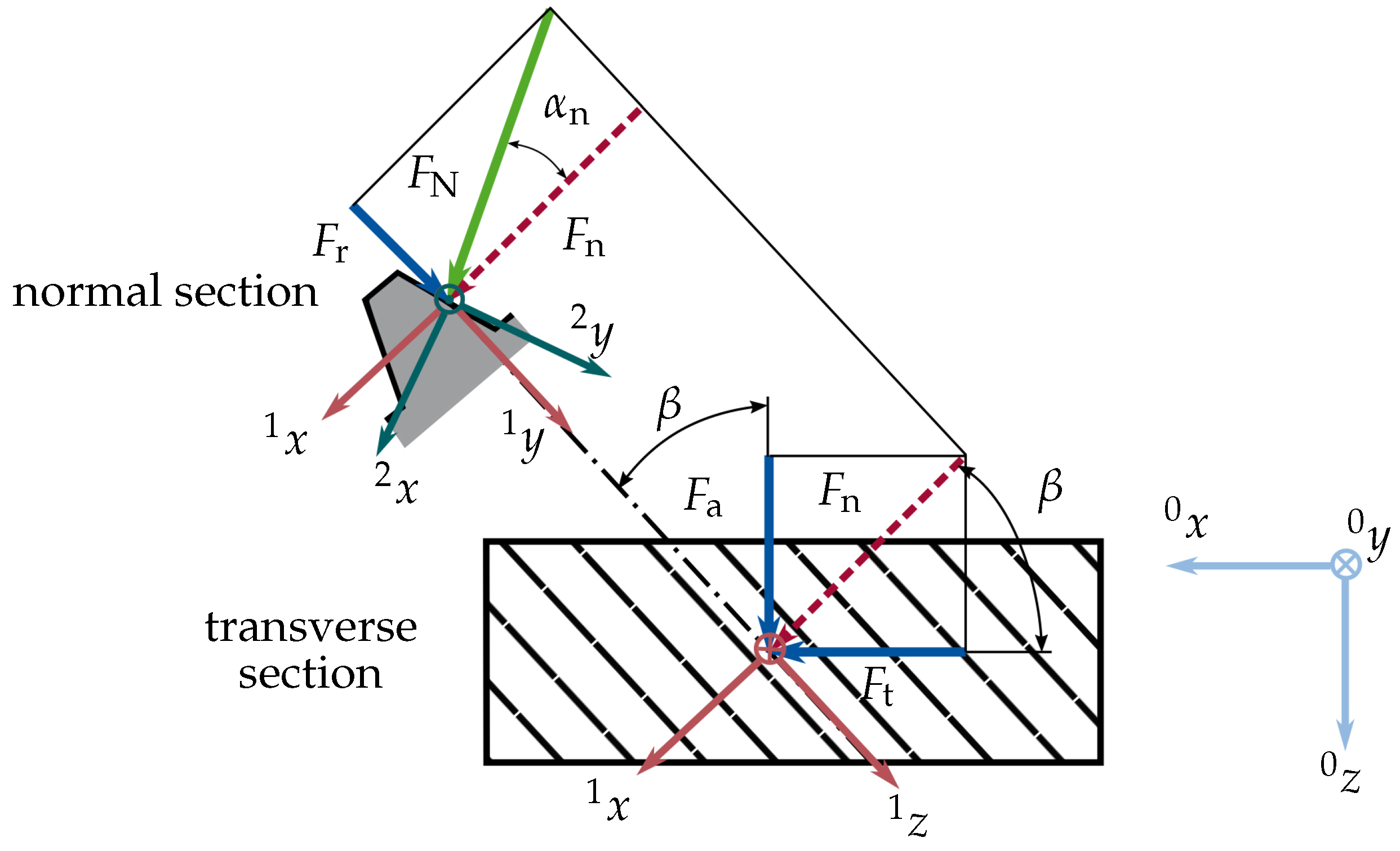
The equation of motion for the second gear wheel follows in the same way [6]. For a helical gear, the torque acting on the two gear wheels can be expressed by the tangential force on the base circle or by the normal tooth force , as shown in Figure 3:
Considering the geometrical relations of the gear forces shown in Figure 3, it can be seen that the normal tooth force is composed of the tangential force , the axial force , and the radial force with helix angle and normal contact angle . Mathematically, the connection of the forces can be described by a coordinate transformation from the global coordinate system Index 0 of the gear wheel to the coordinate system Index 2 in the normal section [6].
In (3) the rotation matrix results from the elementary rotation matrix by rotating around the axis. Furthermore, is obtained from the elementary rotation matrix by rotating around the axis.
The tangential, radial, and axial force can also be determined from the tooth normal force by inversion of (3):
As described in the previous section, the gear excitation forces due to friction are neglected. Therefore, the three-dimensional tooth force vector in the global coordinate system can be represented in the local coordinate system by an one-dimensional force, the normal tooth force , with . This force description in (4) enables an implementation in a multi-body system environment by a one-dimensional force element using a standard variable spring and damper in this local coordinate system [6]. This modular implementation, as suggested in [6], is used for the gear modelling in the following. It allows the development of complicated dynamic gear models with different gear stages within an MBS environment.
3. Modelling the Transient Behaviour of Electric Machines
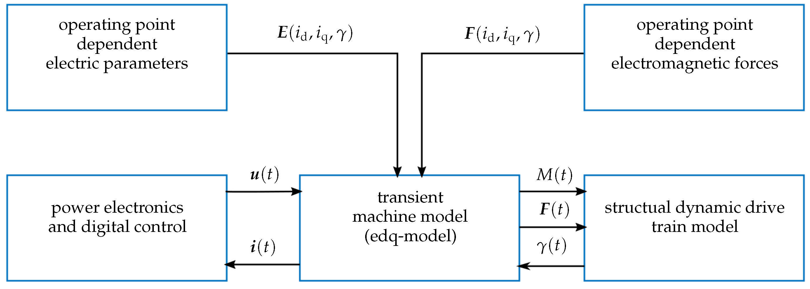
In order to analyse the interactions between a machine, the power electronics, the digital control, and the mechanical system, a transient machine model approach was used, as suggested in [4]. As described in [4], a voltage-driven machine model was used to model the dynamic behaviour of the machine. This model approach gives the opportunity to consider any voltage source . Thereby, non-ideal sinusoidal voltages of the power electronics and the digital control strategy can be considered. Figure 4 gives an overview of the schematic model structure.
The central component of the model is an extended formulation of the voltage equation in the dq axis coordinate system of an electric machine, which allows the inclusion of saturation, cross-coupling, and slotting effects [4]. The interactions between the electric machine model and a mechanical model can be considered through the feedback of the actual rotor angle . The fundamental voltage equation of a three-phase electric machine serves as a starting point:
where describes the vector of the three phase voltages, is the ohmic resistance matrix, is the vector of the three phase currents, and is the matrix of the magnetic flux linkage. Using the commonly known dq-transformation from, e.g., [9], the stationary reference frame of the three phase quantities is transformed into a rotating reference frame of two phase quantities. From this follows the the fundamental voltage equation in dq axis coordinates in tensor notation [10]:
with
is the ohmic resistance matrix, is the vector of the phase currents, is the electrical frequency, is the operating-point-dependent inductance matrix, and is the operating-point-dependent excitation flux linkage.
As described in [10], Equation (6) is transformed into partial differential equations through the use of the total derivative, and the equations are solved according to the respective current derivations. Hence, the partial derivatives can be calculated in advance and do not have to be solved in the system simulation itself. The machine parameters and are modelled in this paper as a function of the machine currents and the rotor angle . In order to determine these parameter dependencies, a series of electromagnetic finite element simulations are performed, which extract the described parameters for each possible operating point by varying , , and the rotor angle .
The same approach is used to extract the electromagnetic forces . Together with the supply voltage from a power electronics model, the extended machine model calculates the resulting transient currents, and forces , and the torque .
4. The Coupled Transient System Model Approach
In order to analyse the transient behaviour of a drivetrain system, the model domains described above must be coupled to an overall system model. This is done on an exemplary drivetrain, the “KinelectricDrive”, which will be presented in the following section.
4.1. The Exemplary Drivetrain
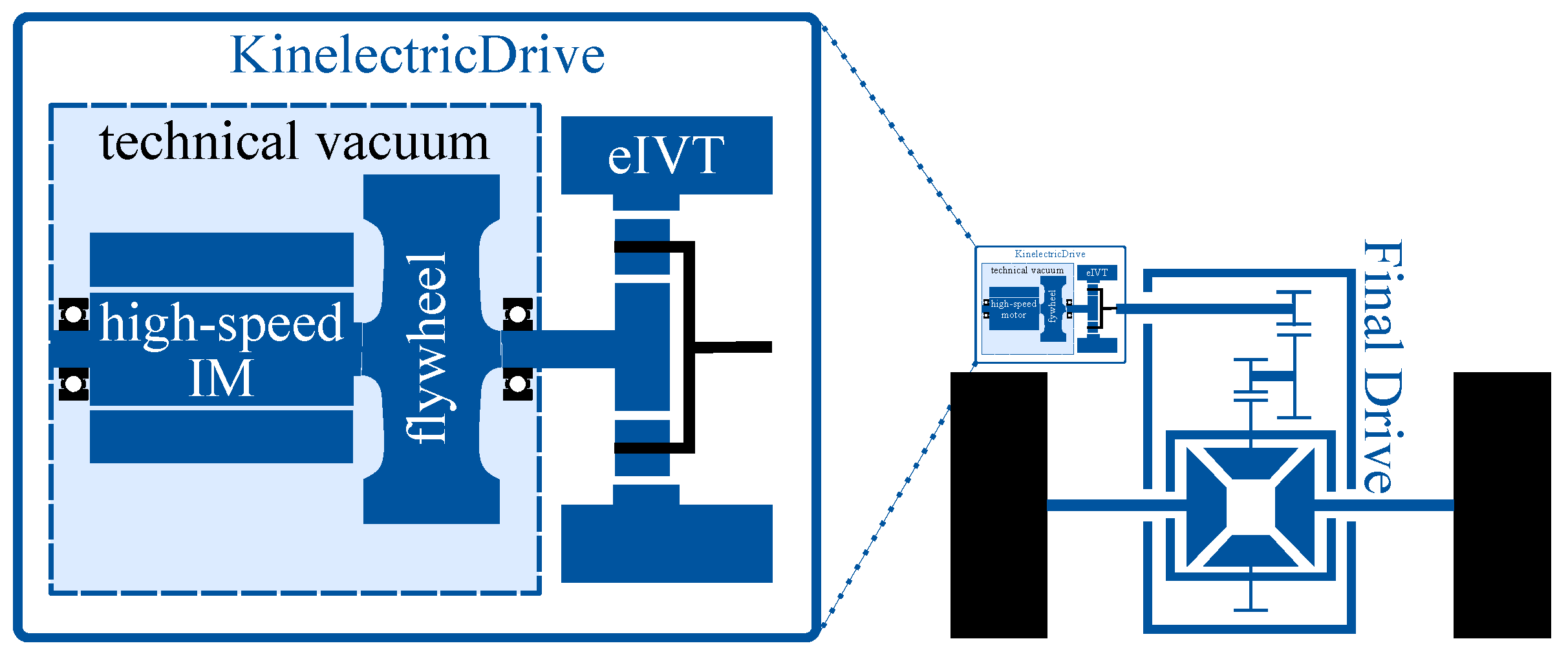
The “KinelectricDrive” is a kinetic–electric power train concept for small vehicles [11]. The name “KineletricDrive” stands for a kinetic–electric drive system that combines the potential of kinetic and electrical energy storage systems on a 48 V basis in one system for automotive applications. The power train and its integration into the vehicle drive are shown schematically in Figure 5.
The central component of the drive system is a high-speed induction machine (IM) with a coupled flywheel. The IM is operated in a technical vacuum to reduce drag losses. In order to realise a maximum short-term mechanical power of the motor of 15 kW in combination with the kinetic energy storage of the flywheel inertia, a maximum speed of up to rpm is achieved.
In order to decouple the flywheel speed from the powertrain output speed, an electric infinite variable transmission (eIVT) is employed. It consists of a helical planetary gear set where the ring is powered by a permanent magnet synchronous machine (PMSM). By controlling the ring torque of the planetary gear set together with a speed-controlled machine on the sun gear, the output power at the carrier can be controlled independently of the flywheel speed and its kinetic energy.
4.2. System Model of the “KinelectricDrive”
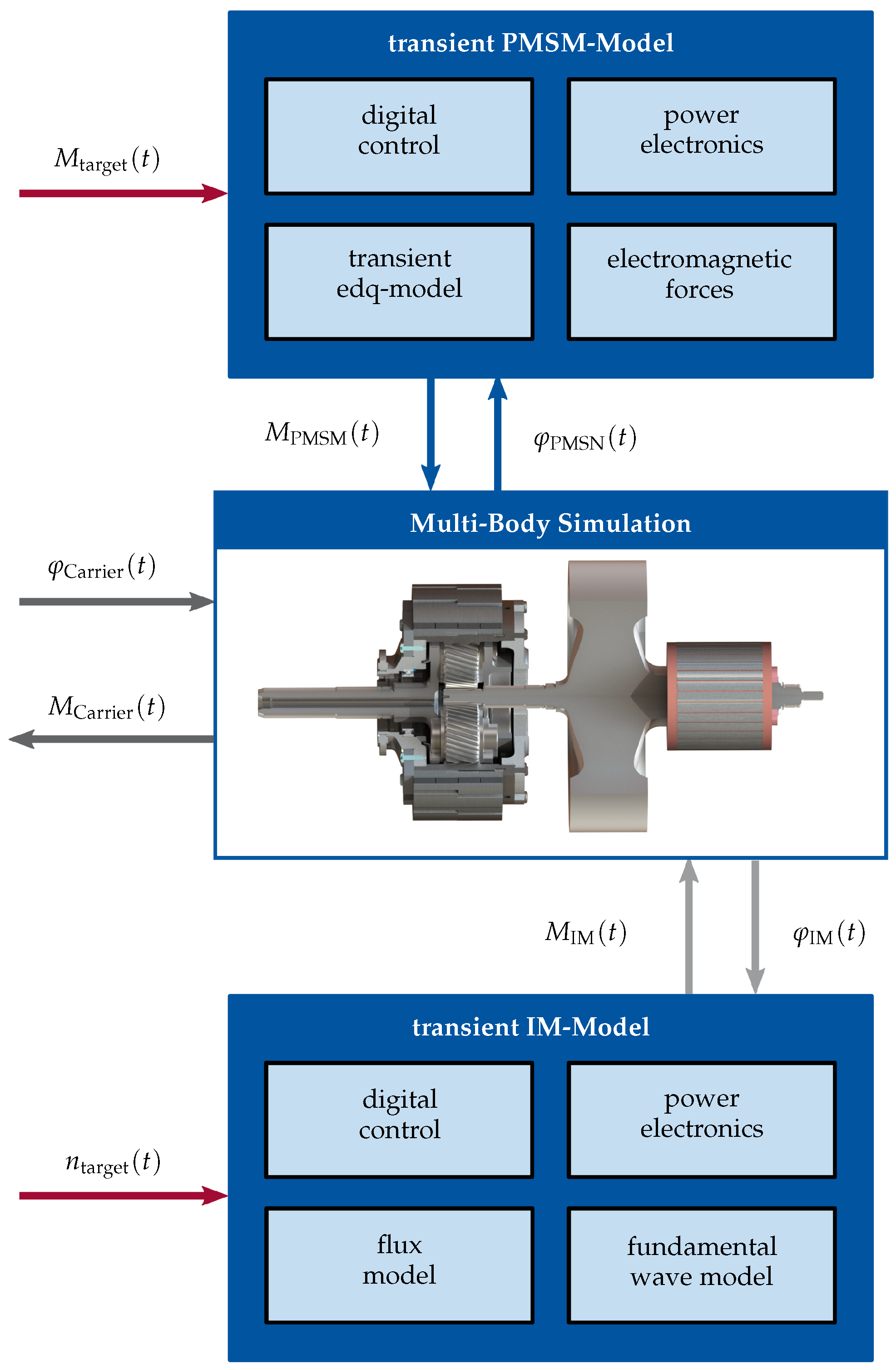
For the development of a multi-physical transient system model of the “KinelectricDrive”, the modelling environment of MATLAB Simulink with the extension toolbox Simscape Multibody was chosen. The focus of this model is on analysing the interactions of the two electrical machines with the rotor dynamics of the drivetrain. Therefore, both machines, the gearbox with the machines’ rotors, and the output shaft were modelled in Simulink. The model structure is shown in Figure 6.
The central component of the system model was the MBS of all rotating components of the “KinelectricDrive”. The rotor of the PMSM at the ring, the drive at the planet carrier with the supported planets, the sun wheel with the flywheel, and the rotor of the high-speed IM were modelled as rigid bodies. All bearings were assumed to be ideally rigid and, thus, offered only one rotational degree of freedom. For the consideration of the dynamic gearing forces, as described in Section 2.2, the force element was implemented and extended for use in a planetary gear, as described in the next section.
Table 1 shows selected resulting mechanical parameters of rigid bodies modelled in the MBS. When comparing the mass and inertia characteristics of the rotor of the high-speed IM to those of the rotor of the PMSM in Table 1, it can be seen that the high-speed machine has approximately twice the inertia of the PMSM due to the coupled flywheel. Furthermore, due to the larger ratio of the planetary gearbox of , the PMSM is designed for a nominal torque that is approximately five times greater than the torque of the IM. Due to these two facts, it is assumed in this paper that the harmonic torques of the induction machine do not contribute significantly to the structural dynamic response of the system. Therefore, a fundamental wave model of the IM was employed as described in [9]. This model was set up together with a field-oriented control and an associated flux model, super-ordinated speed control, and power electronics model.
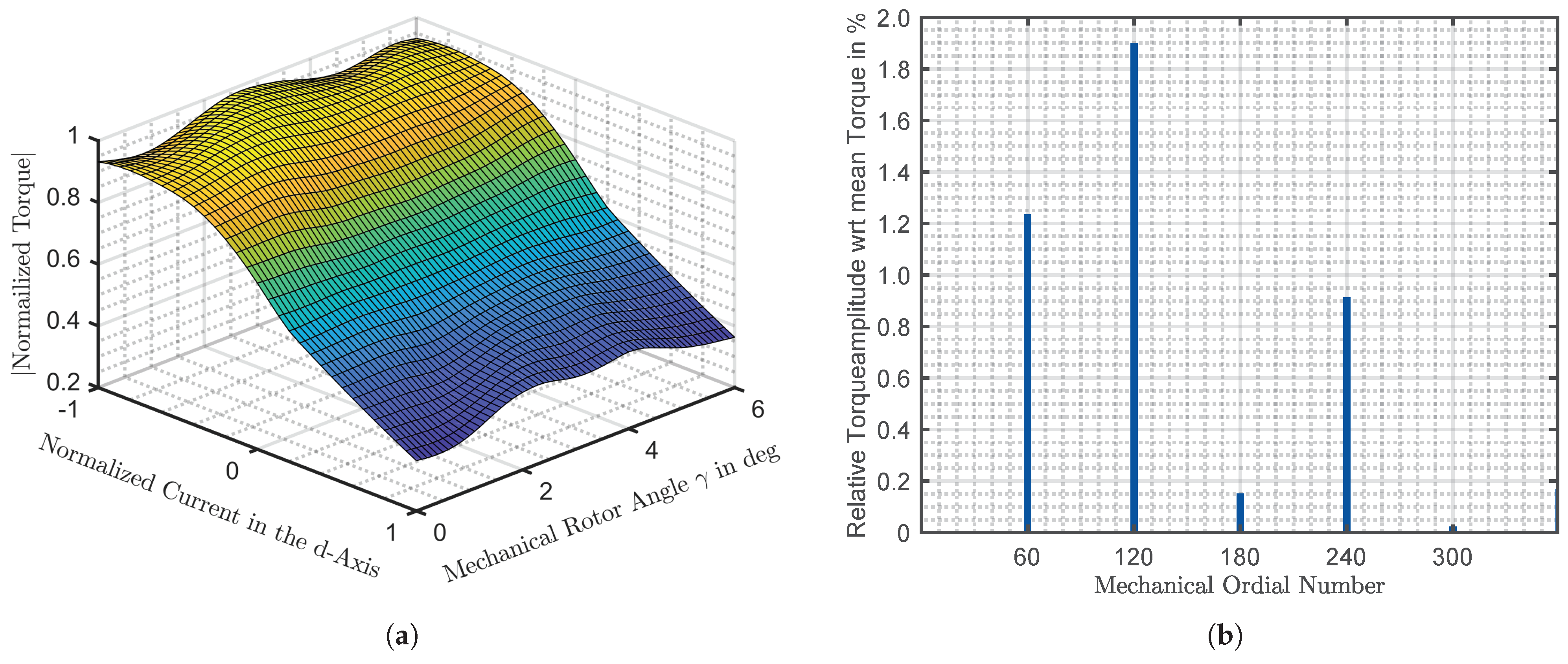
The PMSM at the ring gear was modelled by using the previously described extended transient dq model, which was parametrised by an electromagnetic FEM. The FEM was solved for a total of 30 , 30 current combinations, and 60 rotor positions with a mechanical resolution of degrees. Figure 7a shows the absolute value of the resulting normalised torque for a current in the q-axis of of the maximum value versus the normalised current in the d-axis and the mechanical rotor angle. The slotting effects and saturation of the machines are visible. Figure 7b shows the Fourier decomposition of the resultant torque versus one mechanical revolution for the same q-current component of of the maximum value and a d-current component of of the maximum value.
According to [12], the fundamental ordinal number of the stator slot cogging torque for a three-phase machine with a fractional winding can be determined in a simplified manner according to from the truncated denominator of the number of slots per pole per phase q and the number of stator slots N. In the case of the machine under consideration, the number of slots per pole per phase is , and therefore, the truncated denominator of . With the number of stator slots of , the fundamental ordinal number of the stator slot cogging torque is = 24 × 5 = 120. This ordinal number is visible in the Fourier decomposition of the results, which confirms the results of the finite element model used. The power electronics and the influence of non-ideal sinusoidal currents are not considered in this work. A standard digital control structure is modelled in the form of a torque control.
As the input variables for the MBS model, the transient torques of the two machines are transferred. By solving the non-linear equations of motion within the model, the resulting movements are transferred back to the two machine models. This particular model structure enables the consideration of the transient dynamic behaviour on a system level. The output shaft is modelled in the context of this paper by means of a motion target, whereby the resulting torque at the output can be determined within the MBS model.
4.3. Dynamic Planetary Gear Model
In order to model the dynamic gear forces of the planetary gear, a force element in Simscape Multibody was developed according to the approach described in Section 2.2. Within the element, the resulting bearing forces of the planet wheels were calculated so that the resulting torque at the carrier could be evaluated.
Within the tooth transformation inside the force element, the coordinate transformation in (3) is used to transform the three-dimensional forces in the global system of the planet wheel to the normal section of the gear tooth contact. The reaction forces due to the parameter excitation are transformed back to the global system of the planet wheel according to (4). The coupling is then realised in the normal section of the gear tooth contact using a one-dimensional variable string and a viscous damper.
For the parametrisation of the model, the torque and angle-dependent gear stiffness of the gear pair are required. Such data can be obtained through a gear mesh contact analysis.
The resulting relative contact stiffness, e.g., between the sun and planet gear, for the “KinelectricDrive” is shown in Figure 8. The resulting load and position dependence of the stiffness due to the changing meshing conditions in the tooth contact is visible. This dependency is considered using a two-dimensional look-up table, which is interpolated linearly between the calculated stiffness curves.
In addition to the tooth contact stiffness, the damping constant k is required to describe the dynamics of the tooth contact. In this paper, the damping factor, which allows a calculation of the damping constant, was chosen to be . It is recommended to parametrise the developed model, particularly the damping factor, using measurement data.
Modelling all three planets as single bodies enables the analysis of the influences of an unequal load distribution between the planets on the excitation behaviour.
5. Results
In this section, selected results of the system model of the “KinelectricDrive” are discussed. Since the entire drivetrain is not modelled in the developed model, but only the “KinelectricDrive” itself, the output speed is set to zero for the following analysis. Thus, only one power flow between the two machines is considered in the following analysis.
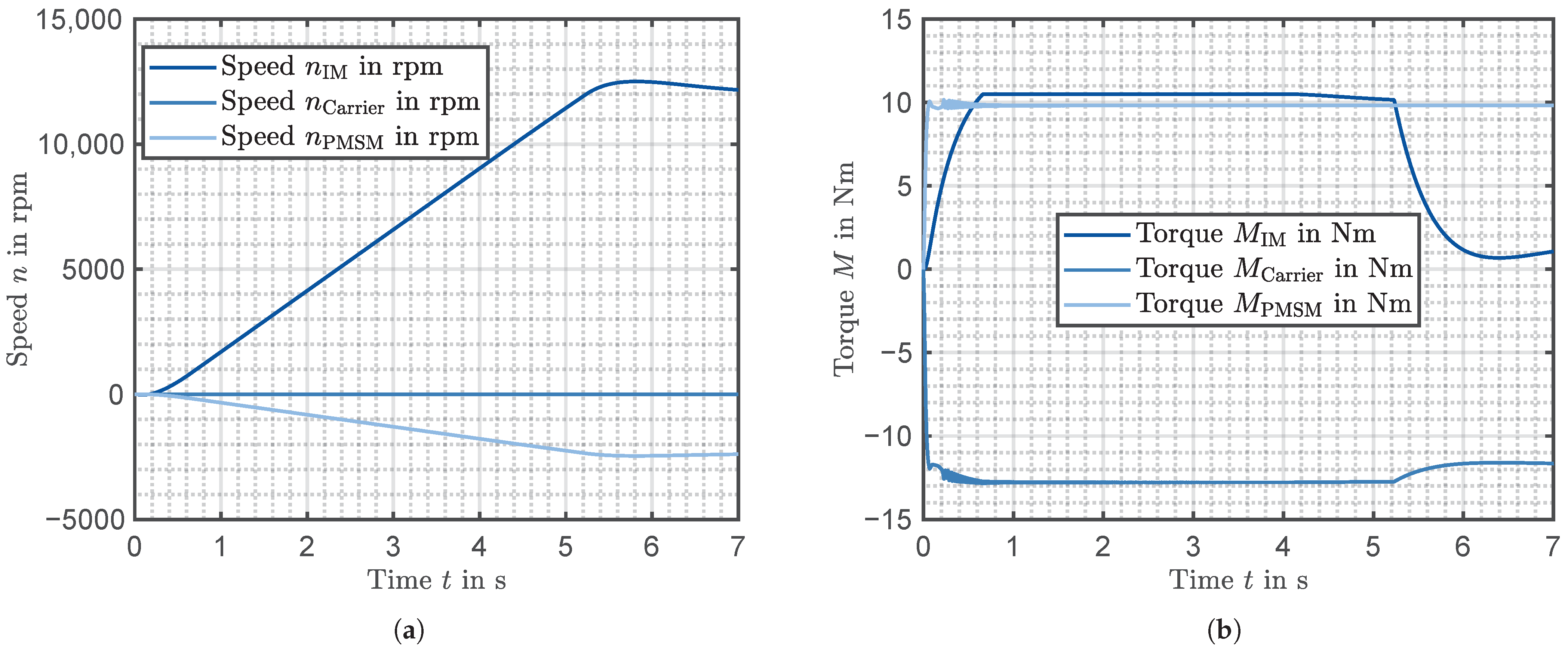
A speed-controlled start-up of the IM under load was performed. The target speed value of the IM was ramped up using a constant slope of 2300 rpm/s. The target speed of the IM was 12,000 rpm. The target of the torque load of the PMSM was controlled by an s-function. During the start-up, a maximum torque of the IM of 10.5 Nm was reached. The stationary torque of 10 Nm of the PMSM was obtained after a time of 0.2 s.
The implementation and solution of the modelling approach proposed in the paper led to a stiff numerical problem. For the solution of the model, a variable step solver, from MATLAB Simulink, was selected. For a convenient evaluation of the results, the numerical values were sampled using a constant sampling frequency of . To reduce aliasing effects, an anti-aliasing filter in the form of a lowpass Butterworth filter was employed.
In the first step, the system was modelled with the standard common gear constraint from the Simscape Multibody library with a stationary gear ratio of . Thereafter, the results were compared to those of the developed dynamic gear model.
Figure 9a shows that the target speed of the IM is reached at a time of after an overshoot of around the target value. Considering the stationary gear ratio of the planetary gear of , the speed of the PMSM at the time is . This result is confirmed by the model, which confirms the appropriateness of the implementation. In Figure 9b, the reaction torques calculated from the MBS of the drive are shown. In the reaction torque of the PMSM, the cogging torque modelled by the edq model is visible through a slight superimposed oscillation of around of the target value. Due to the ideal rigid gear coupling, the cogging torque of the PMSM acts on the output shaft of the carrier in a similar magnitude of around of the mean value.
Figure 10 shows the results using the dynamic gear model. The basic course and the steady-state value of the resulting speeds and the reaction torques of the two models are comparable, which speaks for the correct implementation of the force element presented here. When comparing the resulting reaction torque at the carrier output shaft, significantly increased torque oscillations can be determined. In order to analyse the origin of these in more detail, a spectrogram of the torque at the PMSM and at the carrier is calculated in the following.
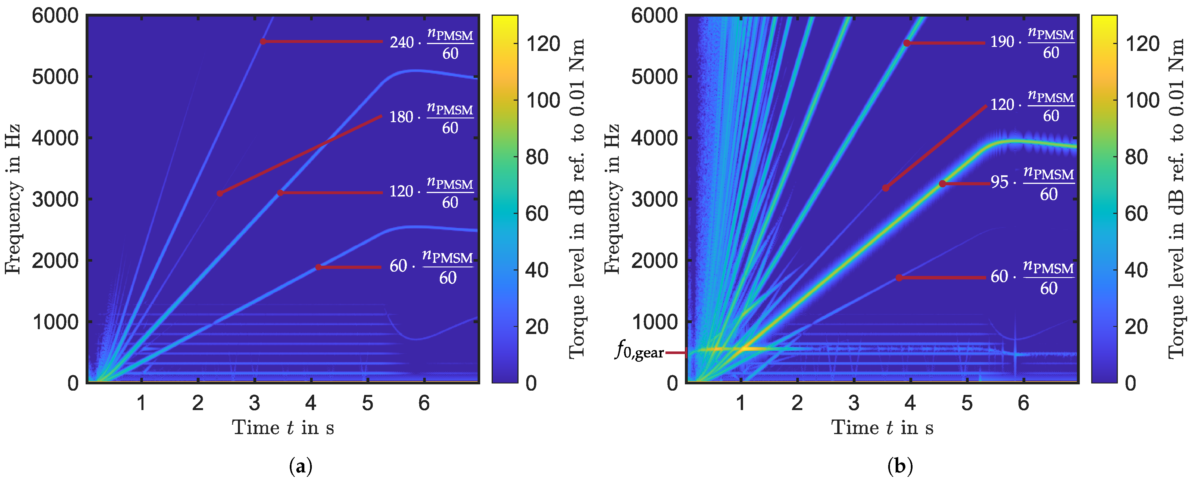
Figure 11a shows the spectrogram of the resulting PMSM torque for the studied start-up operation. The significant frequency orders of the cogging torque with the ordinal numbers are highlighted, which correspond to the results from the electromagnetic FEM simulation in Figure 7.
In Figure 11b, the first orders in the torque with reference to the speed of the PMSM at the carrier are highlighted in the spectrum. Among others, the torque orders with the ordinal numbers occur with reference to the PMSM speed. These can be assigned to the cogging torque of the PMSM. Furthermore, orders with the ordinal numbers occur, for instance. These can be related to the gear meshing frequency, which is the frequency of the parameter excitation of the gear. For the considered gearbox, the gear mesh frequency is obtained from the speed of the PMSM through the number of teeth of the ring gear of or from the speed of the IM through the number of teeth of the sun gear, :
As the torque orders cross the modelled system’s first and only natural frequency (see Figure 11b), a distinct torque oscillation results due to the resonance. This resonance amplification is particularly evident when the fundamental order of the gear mesh excitation itself is at the natural resonant frequency at time (see Figure 10b and Figure 11b). Due to the load-dependent stiffness of the gearing contact (see Figure 8), the resonance frequency of the system is not constant, but load dependent. This load dependency can be seen in the spectrogram in Figure 11b, for example, during the start-up process, and when the target speed is reached during the load change as the natural frequency changes. With increasing torque, the gear stiffness increases (see Figure 8). Since the inertia of the system is constant, according to the simplified relation for a one-mass oscillator , the natural frequency of the system will increase. For example, linearising the system around the operating point, e.g., for the time for the starting phase of the system, gives the natural frequency with the inertias and the current effective stiffness as . For the time , the torque of the IM has reached the steady state (see Figure 10b), and the linearised eigenfrequency around this operating point results in .
The proposed model allows the study of load changes, which frequently occur in drive cycles. The transient behaviours of the machines and the controllers are considered. This allows, for example, the study of a controller’s parameters for their interaction with the rotor dynamics of a drivetrain. Furthermore, the nonlinearities of the gear mesh contact were included in the simulation. Therefore, the load-dependent changes in the system’s natural frequencies and the parameter excitation were taken into account. This overall system model serves as a starting point for analysing the structural dynamic interactions of a drivetrain in detail and for gaining a deeper understanding of the influences on complex drivetrains. A comparison with measured data should be carried out due to the assumption of the damping ratio made here, and this is planned. Finally, this modelling approach gives the possibility of calculating the resulting excitation forces, e.g., the resulting bearing and electromagnetic forces. These can be inputs for a more detailed acoustic and vibration simulation of a drivetrain.
6. Conclusions
In this work, a transient system model for the analysis of structural dynamic interactions in electric drivetrains with gearboxes was developed. The multi-body simulation (MBS) approach was selected. In order to model the dynamic gear forces, a force element in the MBS was implemented and a transient electric machine model was selected. Within this model, the machine controllers were considered. The structural dynamic model was finally coupled to the electric machine model in the time domain.
Compared to commonly used system approaches for noise and vibration analyses of electric drivetrains, in which the coupling is performed in the frequency domain, the presented methodology allows the consideration and analysis of the interactions of the controllers, the electric machine dynamics, and the non-linear structural dynamic response of gears, which are commonly used in electric drivetrains. This particular modelling approach gives the ability to analyse not only steady-state operating points, but also transient load changes and their impact on the system.
The proposed modelling approach was applied to an exemplary drivetrain. Using this drivetrain, a comparison of a controlled start-up of the system with a common gear constraint was made. It was shown that the model provides plausible results. Furthermore, the calculated transient cogging torque of the synchronous machine used and the resulting output torque of the drivetrain were analysed in a spectrum, and excitation orders were assigned to the modelled effects. Finally, the influence of the load dependence of the gear tooth contact on the vibration parameter of the natural frequency of the system was described.
The proposed model can be used as a starting point for a deeper analysis of system interactions and their influences on machine controllers, as well as for detailed vibration and acoustic analyses. A comparison of the results with measurements is planned.
Author Contributions
Conceptualisation, M.F. and D.B.; methodology, M.F.; software, M.F. and J.P.R.; formal analysis, M.N.; writing—original draft preparation, M.F.; writing—review and editing, J.P.R., D.B., M.N. and K.H.; supervision, D.B. and K.H. All authors have read and agreed to the published version of the manuscript.
Funding
This paper was developed in the context of the cooperative project “KinelectricDrive” and was financially supported by the German Federal Ministry of Economic Affairs and Energy (BMWi), reference number 01MY14006B.
Conflicts of Interest
The funders had no role in the design of the study; in the collection, analyses, or interpretation of data; in the writing of the manuscript, or in the decision to publish the results.
Abbreviations
The following abbreviations are used in this manuscript:
| NVH | Noise, Vibration, and Harshness |
| MBS | Multi-Body Simulation |
| FEM | Finite Element Method |
| BEM | Boundary Element Method |
| SEA | Statistical Energy Analysis |
| IM | Induction Machine |
| PMSM | Permanent Magnet Synchronous Machine |
| eIVT | Electric Infinite Variable Transmission |
References
- Holehouse, R.; Shahaj, A.; Michon, M.; James, B. Integrated approach to NVH analysis in electric vehicle drivetrains. J. Eng. 2019, 2019, 3842–3847. [Google Scholar] [CrossRef]
- Rick, S.; Putri, A.K.; Franck, D.; Hameyer, K. Hybrid Acoustic Model of Electric Vehicles: Force Excitation in Permanent-Magnet Synchronous Machines. IEEE Trans. Ind. Appl. 2016, 52, 2979–2987. [Google Scholar] [CrossRef]
- Humbert, L.; Pellerey, P.; Cristaudo, S. Electromagnetic and Structural Coupled Simulation to Investigate NVH Behavior of an Electrical Automotive Powertrain. SAE Int. J. Altern. Powertrains 2012, 1, 395–404. [Google Scholar] [CrossRef]
- Herold, T.; Franck, D.; Lange, E.; Hameyer, K. Extension of a D-Q Model of a Permanent Magnet Excited Synchronous Machine by Including Saturation, Cross-Coupling and Slotting Effects. In Proceedings of the 2011 IEEE International Electric Machines & Drives Conference (IEMDC), IEMDC 2011, Niagara Falls, ON, Canada, 15–18 May 2011. [Google Scholar]
- Klocke, F.; Brecher, C. Zahnrad-und Getriebetechnik: Auslegung—Herstellung—Untersuchung—Simulation; Hanser: München, Germany, 2017. [Google Scholar]
- Dackermann, T.; Miller, S.; Hedrich, L.; Dölling, R. Flexible Gear Model Library—Vibration Excitation Mechanisms and Gear Force Calculation. In Proceedings of the Modelling, Identification and Control/827: Computational Intelligence, Innsbruck, Austria, 16–17 February 2015. [Google Scholar] [CrossRef]
- Andreas, E.; Fastl, H.; Kerber, S.; Hobelsberger, J.; Jebasinski, R.; Klerk, D.D.; Moosmayr, T.; Saemann, E.U. Handbuch Fahrzeugakustik: Grundlagen, Auslegung, Berechnung, Versuch; ATZ-MTZ Fachbuch, Vieweg + Teubner: Wiesbaden, Germany, 2012. [Google Scholar]
- Bauchau, O.A. Flexible Multibody Dynamics. In Solid Mechanics and Its Applications; Springer Science + Business Media B.V.: Dordrecht, The Netherlands, 2011; Volume 176. [Google Scholar]
- Gerling, D. Electrical Machines; Springer Berlin Heidelberg: Berlin/Heidelberg, Germany, 2015; Volume 4. [Google Scholar] [CrossRef]
- Herold, T.; Franck, D.; Böhmer, S.; Schröder, M.; Hameyer, K. Transientes Simulationsmodell für lokale Kraftanregungen elektrischer Antriebe. e i Elektrotechnik Und Informationstechnik 2015, 132, 46–54. [Google Scholar] [CrossRef]
- Butterweck, D.; Hombitzer, M.; Hameyer, K. Analysis and Evaluation of Electric Motor Topologies for a Kinematic-Electric 48 Volt Powertrain. In Proceedings of the 26th Aachen Colloquium Automobile and Engine Technology, Aachen, Germany, 9–11 October 2017. [Google Scholar]
- Jurisch, F. Nutrastmomente in Elektrischen Maschinen: Neue Betrachtungsweise und Maßnahmen zur Gezielten Beeinflussung; Vacuumschmelze GmbH & Co KG: Hanau, Germany, 2003. [Google Scholar]
Figure 1.
Common simulation approaches and their typical areas of application according to [7].
Figure 1.
Common simulation approaches and their typical areas of application according to [7].

Figure 2.
Torsional vibration model with two degrees of freedom [6].
Figure 2.
Torsional vibration model with two degrees of freedom [6].

Figure 3.
Tooth forces with extension of the coordinate systems used.

Figure 4.
Schematic structure of the extended dq-model (edq-model) according to [4].
Figure 4.
Schematic structure of the extended dq-model (edq-model) according to [4].

Figure 5.
Schematic layout of the “KinelectricDrive” according to [11].
Figure 5.
Schematic layout of the “KinelectricDrive” according to [11].

Figure 6.
Schematic structure of the proposed system model.

Figure 7.
Results of the electromagnetic finite element model: (a) Synchronous machine torque as a function of the d-current component and rotor angle; (b) Fourier decomposition of the synchronous machine torque for one mechanical rotation.
Figure 7.
Results of the electromagnetic finite element model: (a) Synchronous machine torque as a function of the d-current component and rotor angle; (b) Fourier decomposition of the synchronous machine torque for one mechanical rotation.

Figure 8.
Gear mesh stiffness of the sun and planet wheels.

Figure 9.
Results of the transient system model using an ideal gear constraint: (a) Speeds of the different shafts; (b) Reaction torques of the different shafts.
Figure 9.
Results of the transient system model using an ideal gear constraint: (a) Speeds of the different shafts; (b) Reaction torques of the different shafts.

Figure 10.
Results of the transient system model using the developed force element: (a) Speeds of the different shafts; (b) Reaction torques of the different shafts.
Figure 10.
Results of the transient system model using the developed force element: (a) Speeds of the different shafts; (b) Reaction torques of the different shafts.

Figure 11.
Results of the transient system model using the developed force element: (a) Spectrogram of the transient torque of the PMSM; (b) Spectrogram of the reaction torque at the carrier shaft.
Figure 11.
Results of the transient system model using the developed force element: (a) Spectrogram of the transient torque of the PMSM; (b) Spectrogram of the reaction torque at the carrier shaft.


Table 1.
Mechanical parameters of modelled bodies.
| Component | Mass m in | Moment of Inertia around the Main Axis of Rotation in |
|---|---|---|
| Rotor of high-speed induction machine (IM) with coupled flywheel | 10.3 | 32.80 × 10 |
| Planet gear wheel | 0.1 | 0.03 × 10 |
| Planet carrier with outputshaft | 1.0 | 1.03 × 10 |
| Rotor of permanent magnet synchronous machine (PMSM) | 5.0 | 16.79 × 10 |
Publisher’s Note: MDPI stays neutral with regard to jurisdictional claims in published maps and institutional affiliations. |
© 2021 by the authors. Licensee MDPI, Basel, Switzerland. This article is an open access article distributed under the terms and conditions of the Creative Commons Attribution (CC BY) license (http://creativecommons.org/licenses/by/4.0/).
Share and Cite
MDPI and ACS Style
Franck, M.; Rickwärtz, J.P.; Butterweck, D.; Nell, M.; Hameyer, K. Transient System Model for the Analysis of Structural Dynamic Interactions of Electric Drivetrains. Energies 2021, 14, 1108. https://doi.org/10.3390/en14041108
AMA Style
Franck M, Rickwärtz JP, Butterweck D, Nell M, Hameyer K. Transient System Model for the Analysis of Structural Dynamic Interactions of Electric Drivetrains. Energies. 2021; 14(4):1108. https://doi.org/10.3390/en14041108
Chicago/Turabian StyleFranck, Marius, Jan Philipp Rickwärtz, Daniel Butterweck, Martin Nell, and Kay Hameyer. 2021. "Transient System Model for the Analysis of Structural Dynamic Interactions of Electric Drivetrains" Energies 14, no. 4: 1108. https://doi.org/10.3390/en14041108
Note that from the first issue of 2016, this journal uses article numbers instead of page numbers. See further details here.