Article

Research on Electromagnetic Field, Eddy Current Loss and Heat Transfer in the End Region of Synchronous Condenser with Different End Structures and Material Properties

1
National Engineering Research Center of Large Electric Machines and Heat Transfer Technology, Harbin University of Science and Technology, Harbin 150080, China
2
DIEI, Department of Electrical and Information Engineering, The University of Cassino and South Lazio, 03043 Cassino, Italy
*
Author to whom correspondence should be addressed.
Energies 2021, 14(15), 4636; https://doi.org/10.3390/en14154636
Submission received: 12 June 2021 / Revised: 21 July 2021 / Accepted: 26 July 2021 / Published: 30 July 2021
(This article belongs to the Special Issue Design and Application of Electrical Machines)

Abstract

:
Aiming at the problem of end structure heating caused by the excessive eddy current loss of large synchronous condensers used in ultra-high voltage (UHV) power transmission, combined with the actual operation characteristics of the synchronous condenser, a three-dimensional transient electromagnetic field physical model is established, and three schemes for adjusting the end structure of the condenser under rated condition are researched. The original structure has a copper shield and a steel clamping plate. Scheme 1 has no copper shield but has a steel clamping plate. Scheme 2 has no copper shield but has an aluminum clamping plate. By constructing a three-dimensional fluid–solid coupling heat transfer model in the end of the synchronous condenser, and giving the basic assumptions and boundary conditions, the eddy current loss of the structure calculated by the three schemes is applied to the end region of the synchronous condenser as the heat source, and the velocity distribution of the cooling medium and the temperature distribution of each structure under the three different schemes are obtained. In order to verify the rationality of the numerical analysis model and the effectiveness of the calculation method, the temperature of the inner edge of the copper shield in the end of the synchronous condenser is measured, and the temperature calculation results are consistent with the temperature measurement results, which provides a theoretical basis for the electromagnetic design, structural optimization, ventilation and cooling of the synchronous condenser.

1. Introduction

The 300 Mvar synchronous condenser can not only generate reactive power for transmission systems, improve the power factor of power grids and generate reactive power, but will also not decrease with the voltage drop of the power grid. This condenser is constructed with more attention paid to instantaneous performance, and is capable of fast voltage support, short-term over-current and over-voltage protection, which can provide more powerful guarantees of safe and stable operation of UHV power grids, Therefore, it has become an essential piece of equipment to improve the power quality and effective reactive power compensation of UHV transmission systems.
Due to the large capacity and large stator armature current of synchronous condensers, the stator current generates a strong magnetic leakage field in the end under rated operating conditions, which further induces eddy current loss in the copper shield, clamping plate and finger plate, causing local overheating of the end structure. When the end structure is heated significantly, it may cause abnormal shutdown of the condenser, or even threaten the safety of the power system. Therefore, the reasonable design of the end structure of the condenser is very important in the improvement of the end structure and the reduction in its temperature.
In recent years, researchers have made many achievements in the research of the electromagnetic and heat transfer mechanisms of electromechanical energy conversion equipment [1,2,3,4,5,6,7]. In terms of the research methods of electromagnetic fields, a new idea for calculating the air gap magnetic circuit of a large turbo generator is proposed in [8]. Article [9] presents an analytical algorithm for calculating the leakage reactance of the strand slot in the transposition bar. In relation to the research methods of motor heat transfer performance, in [10], a lumped parameter network is proposed, which can better predict the thermal behavior of the machine. In [11], by employing the lumped-parameter model in the closed circuit of the flow network, the cooling medium flowrate and pressure drop in each element is calculated. In terms of the motor structure improvement and different material properties on the motor performance, a new ring structure is proposed, which can be better decrease the eddy current loss of the ring in [12]. Paper [13] described a new design scheme for a double three-phase asymmetric stator winding permanent magnet multiphase motor. Two kinds of permanent magnet synchronous motor, with the same capacity but different materials, were tested in [14], and the results show that compared with the traditional permanent magnet synchronous motor, the amorphous metal permanent magnet synchronous motor has very low no-load iron loss. In [15], the temperature distribution of the internal structural parts of a large generator with different shielding materials was researched. In paper [16], the traditional copper shield structure of a large turbo generator is transformed into a hollow structure, so that the temperature of the copper shield is reduced. Paper [17] analyzes the electromagnetic loss, stator temperature distribution and performance parameters of a high-speed induction motor with stator cores of different materials. Paper [17] analyzes the multi physical field distribution of a high-speed asynchronous motor with different stator core materials. However, compared with conventional large-scale motor, the end structure of the synchronous condenser for UHV transmission is complex, and its operation specification and assessment index requirements are more stringent than those of conventional motors, and thus, few researchers have researched the influence of the end structure change of the condenser and different material properties on the multiple internal physical fields of the motor.
In this paper, a 300 Mvar large synchronous condenser is taken as the research object, and three schemes of the end structure of the condenser are compared. By establishing a three-dimensional nonlinear transient electromagnetic field model in the end of the condenser, the distributions of magnetic flux leakage and eddy current loss of each structural member are researched. Based on the calculation results of electromagnetic eddy current loss in the end of the condenser, a three-dimensional fluid–solid coupling analysis model is established. The eddy current loss of each structural member in the end of the condenser calculated under the three schemes is applied to the end region of the condenser as a heat source. The velocity distribution of cooling medium and temperature distribution of each structure member under different schemes are obtained, which have significance as points of reference for improving the end structure of the condenser and reducing the temperature of the end structure of the condenser in the future.

2. Solution Domain Model of Electromagnetic Field in the End of Condenser

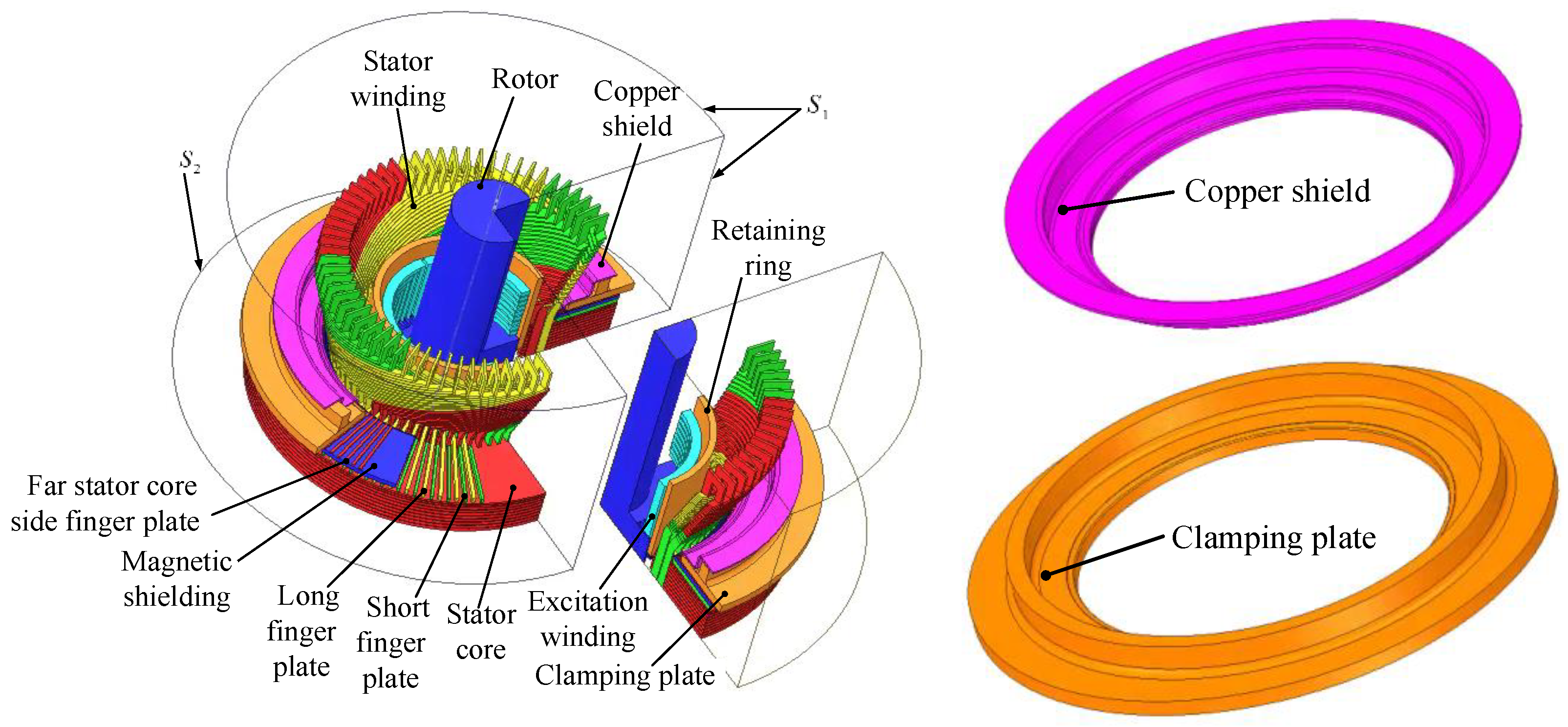
2.1. Physical Model of the End of Condenser

The 300 Mvar synchronous condenser researched in this paper is the first high-capacity condenser to be produced. According to the actual structural characteristics of the end of the condenser, it consists of a copper shield, clamping plate, far stator core side finger plate, magnetic shield, long finger plate, short finger plate, stator core, retaining ring and rotor. The specific structure of the model is shown in Figure 1. The rated parameters and some basic structural parameters of the synchronous condenser are given in Table 1.

2.2. Three Dimensional Electromagnetic Field Mathematical Model of the End Region of the Condenser

The three-dimensional transient electromagnetic field solution domain of the end of the condenser is divided into the eddy current region and the non-eddy current region, in which the clamping finger, clamping plate and copper shield comprise the eddy current region, and the stator winding, rotor excitation winding and air region comprise the non-eddy current region. Taking current vector potential T and scalar magnetic potential ψ as unknown functions, the following mathematical model of the 3D transient electromagnetic field in the end of the large synchronous condenser is established [18,19,20]:
In the eddy current region:
{ × ( ρ × T ) ( ρ T ) + μ ( T ψ ) t = μ H s t ( μ T μ ψ ) = ( μ H s )
In the non-eddy region:
( μ ψ ) = ( μ H s )
where H s is the magnetic field intensity produced by the joint action of the armature current and the excitation current; ρ is resistivity; μ is permeability; t is time.
The boundary conditions of the three-dimensional transient electromagnetic field mathematical model are as follows:
{ ψ n | S 1 = 0 ψ | S 2 = ψ 0
where ψ 0 is the scalar magnetic potential at the initial time; n is the normal vector of the boundary.
The initial conditions are as follows:
{ T | t = 0 = T 0 ( x , y , z ) ψ | t = 0 = ψ 0 ( x , y , z )
where T 0 is the current vector potential at the initial time.
According to the results of the transient electromagnetic field calculation, the instantaneous eddy current density J e ( t ) can be obtained, and the instantaneous eddy current loss P ( e ) ( t ) of each structural part in the end of the condenser can be determined as:
P ( e ) ( t ) = V e | J e ( t ) | 2 σ d V
where V e is the volume of the structure and σ is the conductivity.
Let k be the number of finite element partitions in the calculation area, then according to Formula (5), the eddy current loss in a period T can be obtained as:
P e = e = 1 k 1 T 0 T P ( e ) ( t ) d t

3. Three-Dimensional Fluid–Solid Coupling Heat Transfer Model of the End Domain of the Condenser

The stator of the large synchronous condenser researched in this paper is cooled by air. An axial fan is used in the end of the condenser. Under the action of the fan, the cooling air enters the end domain of condenser from the fan, and a part of the cooling medium enters the stator side of the end to cool the structural parts in the end of the stator; a part of the cooling medium directly enters the rotor position in the end of the condenser, which directly cools the rotor. The cooling medium entering the rotor side in the end and the cooling medium entering the stator side in the end do not converge further, but flow into the straight section from the stator air chamber and the air outlet in the end of the rotor, respectively. Furthermore, the influence of rotor heating on the temperature increase in the end structure of the stator is ignored. The fluid–solid coupling heat transfer model is shown in Figure 2.
Based on the tetrahedron and hexahedron hybrid subdivision, the end structures of the condenser are meshed. In the process of meshing, the stator winding, insulation layer and pressure finger are meshed by hexahedron, and the local size of these structures is controlled. The fluid domain is meshed by tetrahedron. The copper shield and clamping plate are meshed by tetrahedron and hexahedron.

Mathematical Model of Fluid–Solid Coupling Heat Transfer in the End of the Condenser

In view of the theory of fluid mechanics and heat transfer, the fluid flow and heat transfer in the condenser should meet the following three physical conservation laws. The specific conservation equations of mass, momentum and energy are shown below [21].
(1)
The conservation equation of mass is:
ρ 0 t + div ( ρ u ) = 0
where ρ 0 is the fluid density (kg/m3), t is time (s), u is the velocity vector (m/s).
(2)
The momentum conservation equation is:
{ ( ρ 0 u ) t + div ( ρ u u ) = div ( η   g r a d   u ) P 0 x + S u ( ρ 0 v ) t + div ( ρ u v ) = div ( η   g r a d   v ) P 0 y + S v ( ρ 0 w ) t + div ( ρ u w ) = div ( η   g r a d   w ) P 0 z + S w
where u , v and w are, respectively, the components of u in the direction of x , y and z , m/s, η is the turbulent viscosity coefficient, (kg/(m·s)), P 0 is the fluid pressure, Pa, S u , S v and S w are general source terms.
(3)
The energy conservation equation is:
( ρ 0 T ) t + div ( ρ u T ) = div ( λ c   g r a d   T ) + S T
where T is the temperature, K; λ is the thermal conductivity, W/(m·K); c is the specific heat capacity, J/(kg·K); S T is the power density calculated by FEA, W/m3.
(4)
The k-epsilon equation is:
{ ( ρ 0 k ) t + div ( ρ 0 k u ) = div [ ( μ + μ σ k ) g r a d   k ] + G k ρ 0 ε ( ρ 0 ε ) t + div ( ρ 0 ε u ) = div [ ( μ + μ σ ε ) g r a d   ε ] + G 1 ε ε k G k G 2 ε ρ 0 ε 2 k
where ε is the diffusion factor, (m2/s3), k is the kinetic energy of turbulence, (m2/s2); σ k and σ ε are the Prandtl numbers. G 1 ε and G 2 ε are the constants. G k is the turbulence generation rate.
In order to simplify the solution process, the basic assumptions are as follows:
(1)
In this paper, the fluid flow state of the condenser researched is stable, and it is of a steady flow type.
(2)
The Reynolds number of the fluid in the condenser is much larger than 2300, and the flow is turbulent. The standard k-epsilon model is used to solve the fluid.
(3)
The velocity of fluid in the calculation domain of the condenser fluid field is far less than that of sound, so the compressibility of fluid is not considered.
Based on the above assumptions, all the equations are solved using the ANSYS Workbench finite element software. The standard k-ε model is used to deal with the turbulence. The solution parameters of the k-ε model are shown in Table 2.

4. Numerical Analysis of Multiple Physical Fields in the End of the Condenser

4.1. Electromagnetic Field Analysis in the End of the Condenser

In order to better analyze the magnetic flux density distribution of the clamping plate, the circumference of the radius R1–R6 on the upper surface of the lower side of the clamping plate and the position of the inner circle and outer circle on the lower side of the clamping plate are shown in Figure 3. By solving the three-dimensional electromagnetic field in the end of condenser under original structure, the circumferential magnetic flux density distribution with a radius of R1–R6 on the upper surface of the lower side of the clamping plate under the original structure is obtained, as shown in Figure 4. The distributions of the magnetic flux density, radial magnetic flux density, tangential magnetic flux density and axial magnetic flux density of the circumference with radius of R1–R6 are, respectively, given in Figure 4a–d. It can be seen from Figure 4a that the magnetic flux density of the circumference of the clamping plate presents a sinusoidal regular change. The magnetic flux density decreases from R1 to R3 along the radial direction, and increases from R4 to R6 along the radial direction. At the circumference angle of 90° and 270°, the magnetic density reaches the peak value nearby. In Figure 4b, the radial magnetic flux density also presents a sinusoidal regular change. The radial magnetic flux density from R1 to R3 gradually decreases, and the radial magnetic flux density from R4 to R6 gradually increases. It can be seen from Figure 4c that the tangential magnetic flux density reaches a peak near 180° along the circumference. Figure 4d shows that the axial magnetic flux density of the circumference with radius R1–R5 shows a sinusoidal variation with smaller amplitude of magnetic flux density, while the axial magnetic flux density of the circumference with radius R6 shows a larger amplitude. Because there is copper shield above the circumference of radius R1–R5 and no copper shield above the circumference of radius R6, the axial magnetic flux density of the circumference of radius R6 is larger.
In order to further analyze the influence of the three different schemes on the magnetic flux density distribution of the clamping plate, the magnetic flux density distribution of the inner circle and the outer circle of the clamping plate under the three different schemes are shown in Figure 5. It can be seen from Figure 5 that the magnetic flux density of the inner circle and outer circle of clamping plate under the three schemes are sinusoidal in the circumferential direction, and the magnetic flux density of the inner circle side is higher than that of the outer circle side. In Figure 5a, the magnetic flux density of the inner circle side of the original structure gradually decreases along the positive axial direction, and the decreasing trend is larger. The maximum magnetic flux density of the inner circle of the clamping plate is 30.75 mT, which is due to the copper shield in the original structure that can effectively prevent the leakage flux from entering the clamping plate. The maximum magnetic flux density of the outer circle is 7.25 mT. It can be seen from Figure 5b,c that in Scheme 1 and Scheme 2, the maximum magnetic flux density of the inner circle of the clamping plate is 83.04 mT and 112.93 mT, respectively, the maximum magnetic flux density of the outer circle of the clamping plate is 9.73 mT and 7.11 mT, respectively, and the magnetic flux density of the outer circle side gradually increases along the positive axial direction. In conclusion, the change of the magnetic flux density of the outer circle of the clamping plate along the axial direction is small under the three schemes. However, under the three schemes, the magnetic density of the outer circle of the clamping plate is the largest in Scheme 2, the second largest in Scheme 1, and the smallest in the original structure.
According to Formula (6), the eddy current loss of each structural part in the end of the condenser, under three different schemes, is shown in Figure 6. From the calculation results, compared with the original structure, in Scheme 1, the eddy current loss of the upper side of the clamping plate is increased by 5930 W, the eddy current loss of the lower side of the clamping plate is increased by 17,122 W, the eddy current loss of the retaining ring is reduced by 1.14%, and the eddy current loss of the finger plate is increased by 33.76%. Compared with the original structure, under Scheme 2, the eddy current loss increases by 665 W at the upper side of the clamping plate, 2368 W at the lower side of the clamping plate, 0.13% at the retaining ring and 18.37% at the finger plate.

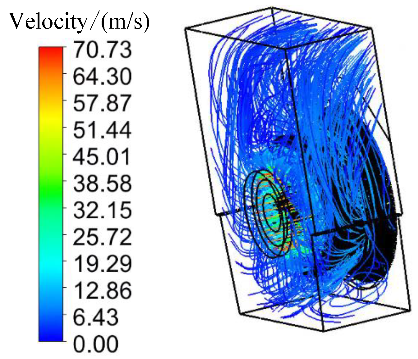
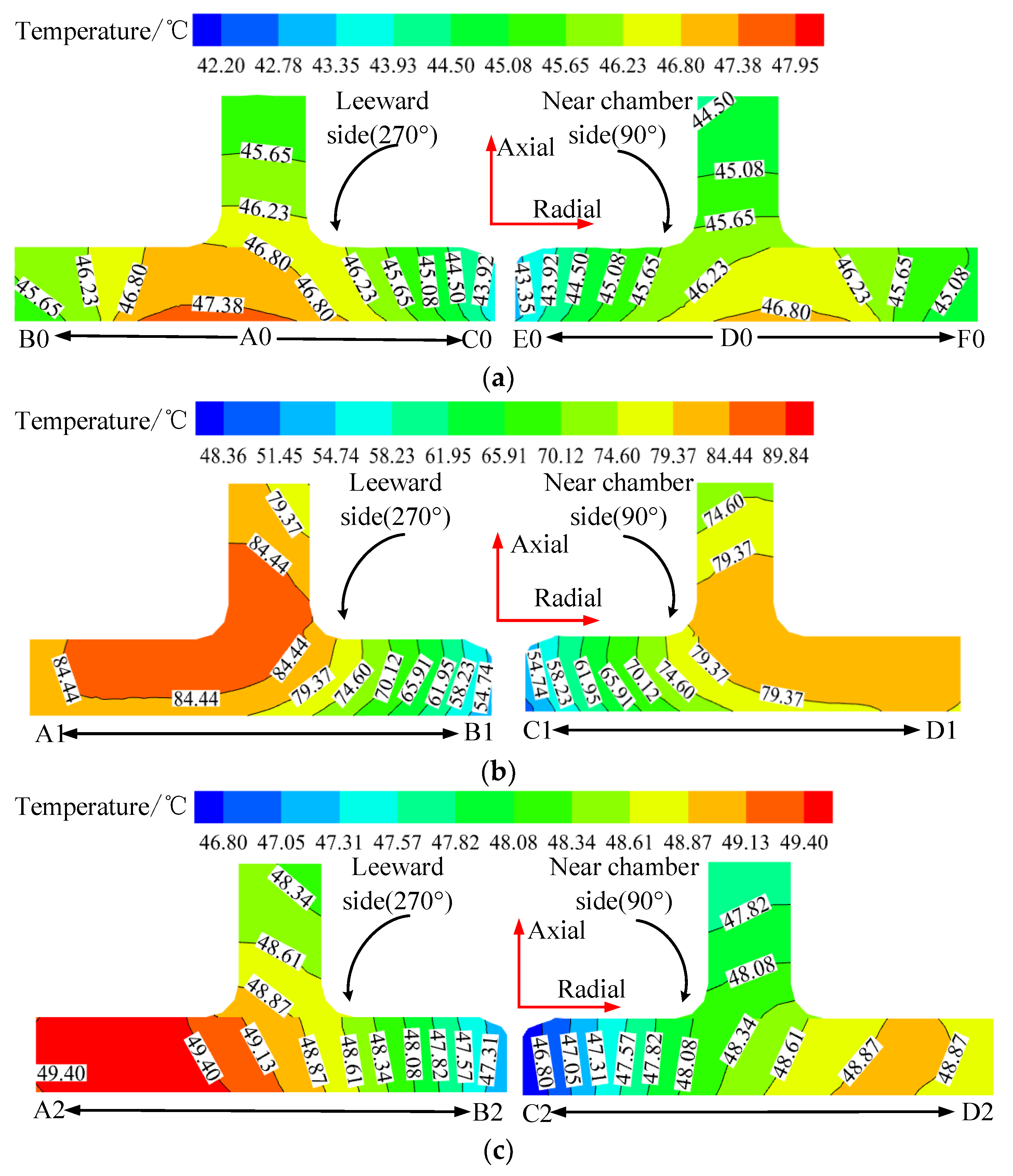
4.2. Analysis of Calculation Results of Fluid–Solid Coupling Field in the End of the Synchronous Condenser

The eddy current loss of the structure is applied to the end domain as the heat source, and then the fluid–solid coupling field is solved. The velocity distribution of cooling medium and the temperature distribution of the structure near the end of synchronous condenser are obtained under three different schemes.
In order to describe the fluid distribution in the fluid domain, the calculated fluid trace distribution in the end region of the condenser is shown in Figure 7. According to the fluid trace distribution, most of the cooling medium flows through the fluid domain from the condenser fan inlet, and then flows out through the stator air cavity after cooling the end stator winding, copper shield, clamping plate and other components.
In order to research the fluid change law near the clamping plate under the three schemes, Figure 8a shows the velocity distribution and fluid temperature distribution of the clamping plate’s leeward side (270°). Figure 8b shows the velocity distribution and fluid temperature distribution of the clamping plate near the chamber side (90°). As can be seen from Figure 8a, on the leeward side, under the original structure, the velocity in the inner circle of the clamping plate increases first and then decreases along the positive axial direction. Under Scheme 1 and Scheme 2, the velocity of cooling medium increases gradually along the positive direction of the inner circle axial direction, and they have the same flow velocity. The fluid temperature of the inner circle of the clamping plate under the original structure is higher than that of Scheme 1 and Scheme 2. This is because the gap between copper shield and clamping plate is small in the original structure, less cooling medium enters into the gap and the circulation is poor. Therefore, the flow rate of the cooling medium under the original structure is smaller and the fluid temperature is higher. Scheme 1 and Scheme 2 have no copper shield, so the cooling medium can flow to the inner circle of the clamping plate better and then cool the inner circle side of the clamping plate. Therefore, the fluid temperature in the inner circle of the clamping plate under the two schemes is lower. In the three schemes, the velocity of the outer circle of the clamping plate decreases slowly along the positive axial direction, but the temperature of the outer circle of the clamping plate in Scheme 1 is the highest, followed by Scheme 2, and that of the original structure is the lowest. This is because the velocity of the cooling medium on the outer circle side of the clamping plate is small, and it is not fully cooled to the outer circle side of the clamping plate. At this time, the fluid temperature on the outer circle side of the clamping plate has a great influence on the heat source of the clamping plate itself. In Figure 8b, on the inner circle side of the clamping plate, the fluid distribution on the near chamber side of the clamping plate is the same as that on the leeward side of the clamping plate. However, compared with the leeward side of the clamping plate, the fluid temperature on the near chamber side of the clamping plate lower than that of the leeward side.
1—Velocity of the inner circle side of the clamping plate of the original structure; 2—velocity of the inner circle side of the clamping plate of Scheme 1; 3—velocity of the inner circle side of the clamping plate of Scheme 2; 4—velocity of the outer circle side of the clamping plate of the original structure; 5—velocity of the outer circle side of the clamping plate of Scheme 1; 6—fluid temperature of the outer circle side of the clamping plate of Scheme 2; 7—fluid temperature of the inner circle side of the clamping plate of the original structure; 8—fluid temperature of the inner circle side of the clamping plate of Scheme 1; 9—fluid temperature of the inner circle side of the clamping plate of Scheme 2; 10—fluid temperature of the outer circle side of the clamping plate of the original structure; 11—fluid temperature of the outer circle side of the clamping plate of Scheme 1; 12—fluid temperature of the outer circle side of the clamping plate of Scheme 2;
In order to explore the influence of the three schemes on the temperature distribution of the clamping plate in detail, Figure 9 shows the temperature contour distribution of the clamping plate on the leeward side and the near chamber side under different schemes. It can be seen from Figure 9 that the temperature of the clamping plate on the leeward side is higher than that on the near chamber side. As shown in Figure 9a, the maximum temperature of the clamping plate is 47.95 °C under the original structure, and the temperature at A0 and D0 in the middle of the clamping plate is higher. From A0 along the radial direction to B0, A0 along the radial direction to C0, D0 along the radial direction to E0, and D0 along the radial direction to F0, the temperature of the clamping plate gradually decreases, and the temperature of the inner circle side of the clamping plate is less than that of the outer circle. It can be seen from Figure 9b that in Scheme 1, the temperature of the clamping plate decreases gradually from A1 to B1 and from D1 to C1. However, the temperature contour of the inner circle side of the clamping plate is dense, and the temperature contour of the outer circle side of the clamping plate is sparse. Therefore, the cooling effect of the inner circle side of the clamping plate is better. On the one hand, the cooling medium velocity is small on the outer circle side of clamping plate. Moreover, in Scheme 1, the heat source of the clamping plate is larger, which leads to the higher temperature outside the clamping plate and the same temperature in a large area. The maximum temperature of the clamping plate is 89.84 °C. According to Figure 9c, the maximum and minimum temperatures of the clamping plate in Scheme 2 are 49.40 °C and 46.80 °C, respectively, which are 1.45 °C and 4.6 °C higher than the maximum and minimum temperatures of the clamping plate in the original structure. The temperature of the clamping plate under Scheme 2 decreases gradually from A2 to B2.
In order to research the influence of the original structure, Scheme 1 and Scheme 2 on the temperature distribution of the far stator core finger plate in the end of the condenser, the temperature distributions of the far stator core finger plate under three different schemes are given in Figure 10a–c. It can be seen from Figure 10 that the temperature of the finger plate near the chamber is lower than that of the finger plate near the leeward chamber. According to the eddy current loss value of finger plate given in Figure 6, the eddy current loss of the finger plate under the three schemes is similar, but the maximum temperatures of the finger plate under the original structure, Scheme 1 and Scheme 2 are 49.91 °C, 80.11 °C and 51.57 °C, respectively. In Scheme 1, the maximum temperature of the finger plate is 30.2 °C higher than that of the original structure. In Scheme 2, the maximum temperature of the finger plate is 1.66 °C higher than that of the original structure. Through comparative analysis, it can be concluded that the temperature of the finger plate is mainly affected by the heat transfer of other structural parts as well as its own heat source.

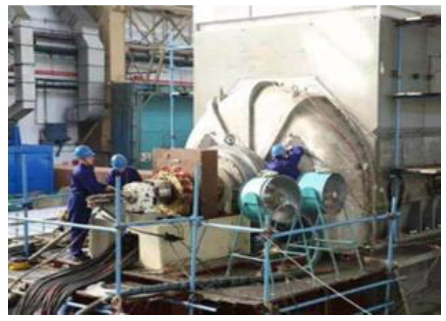
5. Temperature Test and Data Comparison

In order to further verify the correctness of the fluid–solid coupling model of the end of the condenser and the accuracy of the calculation results, the temperature test of the 300 Mvar air-cooled synchronous condenser under rated conditions is carried out. The temperature increase test system of the 300 Mvar condenser is shown in Figure 11. The temperature measurement position of the inner edge of the copper shield of the condenser is shown in Figure 12. The temperature measuring element PT100 is bonded to three positions, A, B and C, of the inner edge of the copper shield.
The temperatures of A, B and C on the inner edge of the copper shield are 57.9 °C, 58.3 °C and 54.2 °C, respectively. The comparison results between the calculated values and the measured values are shown in Table 3. The temperature calculation results are basically consistent with the temperature results of the field test, which can meet the engineering requirements. There is a certain deviation between the copper shield temperature calculation results and the measured temperature values. The reason for the error is that due to the extremely complex structure of the end of condenser, the distance between the stator end windings of the condenser will be different in the assembly process of the condenser, resulting in the uneven distribution of fluid velocity in the end region of the generator. The installation error and unevenness of the copper shield may exist in the actual installation of the project, which will lead to the uneven distribution of the fluid velocity in the ventilation channel between the copper shield and the clamping plate. In addition, the deformation of the end member can cause the uneven distribution of the electromagnetic loss in the end region of the actual condenser, which also leads to the difference between the temperature values measured by the three temperature measuring elements and the calculated values in the inner circle region of the copper shield.

6. Conclusions

Taking a 300 Mvar air-cooled large synchronous condenser as an example, this paper researches the distribution of magnetic field and eddy current loss in the end of the condenser under three different schemes, and then explores the flow diversion law of the cooling medium and the temperature distribution law of the structure under these three schemes. The temperature of the inner edge of the copper shield in the end of the condenser is measured by the PT100 thermistor. The calculated value of the temperature is consistent with the measured value, and the conclusions are as follows:
(1)
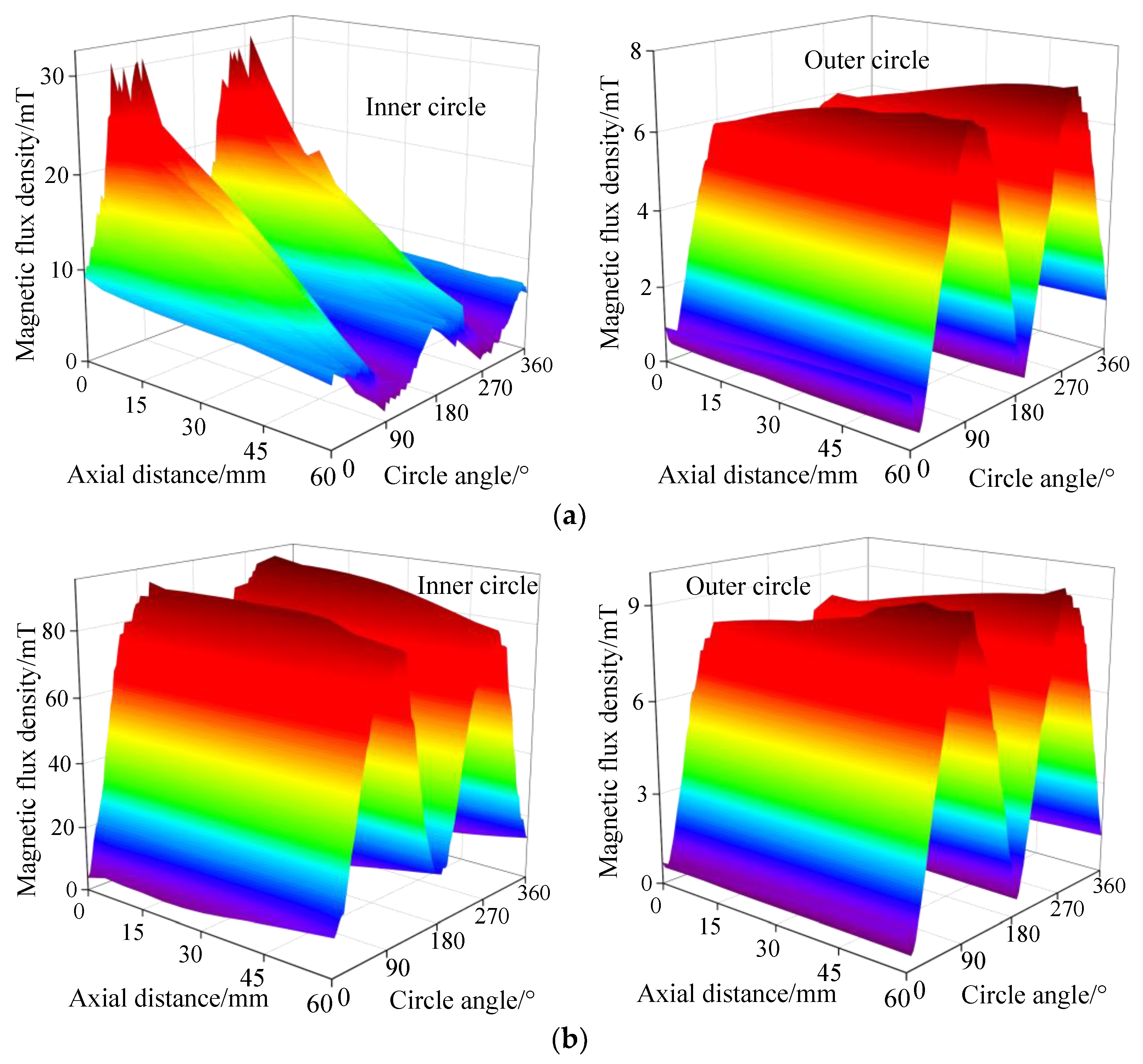
The radial magnetic flux density is the largest in the magnetic flux density component of the upper surface of the lower side of clamping plate under the original structure. Under the three schemes, the magnetic flux density of the inner circle and the outer circle of the clamping plate presents a sinusoidal regular change in the circumferential direction, and the magnetic flux density of the inner circle side is higher than that of the outer circle side. The magnetic flux density of the clamping plate under the original structure is the smallest.
(2)
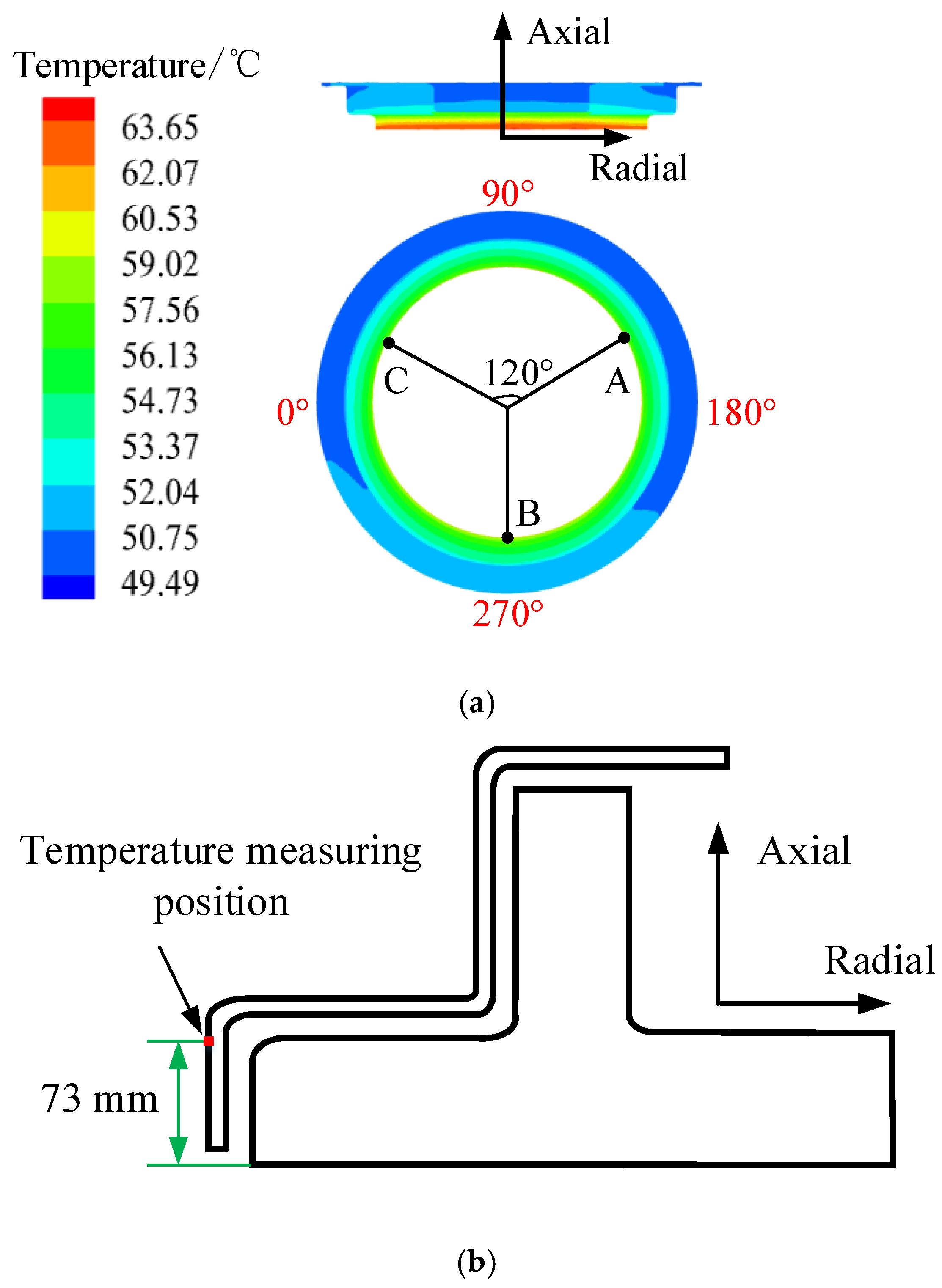
The temperature near the chamber side is lower than that at the leeward side. The velocity of cooling medium at the inner circle side is higher than that at the outer circle side, but the temperature at the inner circle side is lower than that at the outer circle side.
(3)
The eddy current loss (4036 W) of the clamping plate of Scheme 2 is 3023 W higher than that of the original structure (1013 W), but the maximum temperature and minimum temperature of the clamping plate of Scheme 2 are 1.45 °C and 4.6 °C higher than those of the original structure, respectively. The eddy current loss (234 W) of the finger plate of Scheme 2 is 18.37% higher than that of the original structure (277 W), but the maximum temperature and minimum temperature of the finger plate of Scheme 2 are 1.66 °C and 0.54 °C higher than those of the original structure, respectively.
(4)
When Scheme 2 is adopted, the eddy current loss increases more than that of the original structure, but the temperature increases in the clamping plate, finger plate and other structural parts are less. It can be seen that when the copper shield is removed and the steel clamping plate is replaced by the aluminum clamping plate, the end structure can be simplified and the material of copper shield can be saved. The aluminum clamping plate itself can play a shielding role. Due to the temperature increase being lower, other simple and feasible methods can be adopted to reduce the temperature, such as increasing the fan inlet air volume.

Author Contributions

Conceptualization, X.B. and L.W.; methodology, X.B. and L.W.; formal analysis, L.W.; validation, X.B. and L.W.; investigation, L.W.; data curation, L.W.; writing—original draft preparation, X.B.; writing—review and editing, X.B. and L.W.; project administration, X.B. and L.W.; funding acquisition, L.W., X.B., F.M. and M.Z. All authors have read and agreed to the published version of the manuscript.

Funding

This research was funded only by Natural Science Foundation for Excellent Young Scholars of Heilongjiang Province, grant number YQ2021E038.

Conflicts of Interest

All of our authors declare together that there is no conflict of interest.

References

  1. Bian, X.; Liang, Y.P. Circuit Network Model of Stator Transposition Bar in Large Generators and Calculation of Circulating Current. IEEE Trans. Ind. Electron. 2015, 62, 1392–1399. [Google Scholar] [CrossRef]
  2. Gozdowiak, A. Faulty Synchronization of Salient Pole Synchronous Hydro Generator. Energies 2020, 13, 5491. [Google Scholar] [CrossRef]
  3. Wang, L.K.; Huo, F.Y.; Li, W.L. A Novel Dual Three-Phase Permanent Magnet Synchronous Motor with Asymmetric Stator Winding. IEEE Trans. Magn. 2013, 49, 939–945. [Google Scholar] [CrossRef]
  4. Tao, D.J.; Zhou, K.L.; Lv, F.; Dou, Q.P.; Wu, J.X.; Sun, Y.T.; Zou, J.B. Magnetic Field Characteristics and Stator Core Losses of High-Speed Permanent Magnet Synchronous Motors. Energies 2020, 13, 535. [Google Scholar] [CrossRef] [Green Version]
  5. Ding, S.Y.; Li, Z.J. Analysis of Fluid Field Characteristics and Structure Optimization inside Stator Domain for Air-cooled Turbo-generator. In Proceedings of the 2020 12th IEEE PES Asia-Pacific Power and Energy Engineering Conference (APPEEC), Nanjing, China, 20–23 September 2020; pp. 1–5. [Google Scholar]
  6. Traxler-Samek, G.; Zickermann, R.; Schwery, A. Cooling airflow, losses, and temperatures in large air-cooled synchronous machines. IEEE Trans. Ind. Electron. 2010, 57, 172–180. [Google Scholar] [CrossRef]
  7. Ding, S.Y.; Zhang, X.F.; Guan, T.Y. Analysis of Heat Transfer Performance for Megawatt Wind Generator in High Altitude Extreme Conditions. In Proceedings of the 2014 17th International Conference on Electrical Machines and Systems (ICEMS), Hangzhou, China, 22–25 October 2014; pp. 2340–2346. [Google Scholar]
  8. Zhang, L.L.; Ling, Y.P.; Bian, X. Analysis of Magnetic Flux Density of Air Gap in Turbo-Generators Using Equivalent Magnetic Network Method. In Proceedings of the 2019 22nd International Conference on Electrical Machines and Systems (ICEMS), Harbin, China, 11–14 August 2019; pp. 1–5. [Google Scholar]
  9. Ling, Y.P.; Bian, X.; Yu, H.H. Analytic Algorithm for Strand Slot Leakage Reactance of the Transposition Bar in an AC Machine. IEEE Trans. Ind. Electron. 2014, 61, 5232–5240. [Google Scholar] [CrossRef]
  10. Jing, T.T.; Liu, G.H.; Zhou, H.W. Simplified Thermal Modeling of Fault-Tolerant Permanent-Magnet Motor by Using Lumped Parameter Network. In Proceedings of the 2014 IEEE Conference and Expo Transportation Electrification Asia-Pacific (ITEC Asia-Pacific), Beijing, China, 31 August–3 September 2014; pp. 1–5. [Google Scholar]
  11. Zhao, W.X.; Cao, D.H.; Ji, J.H. A Generalized Mesh-Based Thermal Network Model for SPM Machines Combining Coupled Winding Solution. IEEE Trans. Ind. Electron. 2021, 68, 116–127. [Google Scholar] [CrossRef]
  12. Ling, Y.P.; Yu, H.H.; Bian, X. Finite-Element Calculation of 3-D Transient Electromagnetic Field in End Region and Eddy-Current Loss Decrease in Stator End Clamping Plate of Large Hydrogenerator. IEEE Trans. Ind. Electron. 2015, 62, 7331–7338. [Google Scholar] [CrossRef]
  13. Demir, Y.; Aydin, M. A Novel Dual Three-Phase Permanent Magnet Synchronous Motor with Asymmetric Stator Winding. IEEE Trans. Magn. 2016, 52, 8105005. [Google Scholar] [CrossRef]
  14. Tong, W.M.; Dai, S.H.; Wu, S.N. Performance Comparison Between an Amorphous Metal PMSM and a Silicon Steel PMSM. IEEE Trans. Magn. 2019, 45, 8102705. [Google Scholar] [CrossRef]
  15. Han, J.C.; Zheng, P.; Sun, Y.T. Influence of Electric Shield Materials on Temperature Distribution in the End Region of a Large Water–Hydrogen–Hydrogen-Cooled Turbogenerator. IEEE Trans. Ind. Electron. 2020, 67, 3431–3441. [Google Scholar] [CrossRef]
  16. Huo, F.Y.; Hai, J.C.; Li, W.L. I Influence of Copper Shield Structure on 3-D Electromagnetic Field, Fluid and Temperature Fields in End Region of Large Turbogenerator. IEEE Trans. Ind. Electron. 2013, 28, 832–840. [Google Scholar]
  17. Fan, Z.; Yi, H.; Xu, J.; Xie, K.; Qi, Y.; Ren, S.; Wang, H. Performance Study and Optimization Design of High-Speed Amorphous Alloy Induction Motor. Energies 2021, 14, 2468. [Google Scholar] [CrossRef]
  18. Wang, L.K.; Li, W.L.; Huo, F.Y. Influence of Underexcitation Operation on Electromagnetic Loss in the End Metal Parts and Stator Step Packets of a Turbogenerator. IEEE Trans. Energy Convers. 2014, 29, 748–757. [Google Scholar] [CrossRef]
  19. Wang, L.K.; Li, W.L. Assessment of the Stray Flux, Losses, and Temperature Rise in the End Region of a High-Power Turbogenerator Based on a Novel Frequency-Domain Model. IEEE Trans. Ind. Electron. 2018, 65, 4503–4513. [Google Scholar] [CrossRef]
  20. Huo, F.Y.; Li, W.L.; Wang, L.K. Numerical Calculation and Analysis of Three-Dimensional Transient Electromagnetic Field in the End Region of Large Water–Hydrogen–Hydrogen Cooled Turbogenerator. IEEE Trans. Ind. Electron. 2014, 61, 188–195. [Google Scholar] [CrossRef]
  21. Li, W.L.; Han, J.C.; Huo, F.Y. Influence of the End Ventilation Structure Change on the Temperature Distribution in the End Region of Large Water–Hydrogen–Hydrogen Cooled Turbogenerator. IEEE Trans. Energy Convert. 2013, 28, 278–288. [Google Scholar]
Figure 1. Physical model of the end region of the condenser.
Energies 14 04636 g001
Figure 2. Physical model of the fluid–solid coupling field in the fluid domain.
Energies 14 04636 g002
Figure 3. Clamping plate sampling position: (a) location of inner and outer surface of clamping plate; (b) inner circle and outer circle of clamping plate.
Energies 14 04636 g003
Figure 4. Magnetic flux density in different directions on the surface of the clamping plate of the original structure: (a) magnetic flux density of the outer surface of the clamping plate; (b) radial magnetic flux density of the outer surface of the clamping plate; (c) tangential magnetic flux density of the outer surface of the clamping plate; (d) axial magnetic flux density of the outer surface of the clamping plate.
Energies 14 04636 g004
Figure 5. Magnetic density distribution in the inner and outer circle of the clamping plate: (a) original structure; (b) Scheme 1; (c) Scheme 2.
Energies 14 04636 g005aEnergies 14 04636 g005b
Figure 6. Distribution of eddy current loss in the end domain of the synchronous condenser.
Energies 14 04636 g006
Figure 7. Trace distribution in the end of the synchronous condenser.
Energies 14 04636 g007
Figure 8. The fluid distribution of clamping plate on the leeward side and the near chamber side: (a) leeward side (270°); (b) near chamber side (90°).
Energies 14 04636 g008
Figure 9. The temperature contour distribution of the clamping plate on the leeward side and the near chamber side: (a) original structure; (b) Scheme 1; (c) Scheme 2.
Energies 14 04636 g009
Figure 10. Temperature of far core finger plate under different schemes: (a) original structure; (b) Scheme 1; (c) Scheme 2.
Energies 14 04636 g010
Figure 11. Temperature increase test system of the 300 Mvar synchronous condenser.
Energies 14 04636 g011
Figure 12. Temperature measurement position of the inner edge of the copper shield: (a) the temperature of the copper shield and the circumferential temperature measurement position; (b) the axial temperature measurement position of the copper shield.
Energies 14 04636 g012
Table 1. The rated parameters and some basic structural parameters of the condenser.
ParametersValue
Rated Capacity/Mvar300
Rated voltage/kV20
Rated current of stator/A
Rated rotate speed/ r min 1
8660
3000
Rated excitation current/A
Stator external diameter/mm
2381
2950
Number of stator slots72
Number of poles2
Table 2. Parameters of the k-ε model.
ParametersValue
σ k 1.30
σ ε 1.30
G 1 ε
G 2 ε
1.44
1.92
Energy Prandtl number
Wall Prandtl number
0.85
0.85
Table 3. Comparison of calculated and measured temperature.
StructurePositionMeasured Value/°CCalculated Value/°C
Copper shieldA57.958.7
B58.359.4
C54.258.6
Publisher’s Note: MDPI stays neutral with regard to jurisdictional claims in published maps and institutional affiliations.

