
Experimental Investigation of a Double-Acting Vane Pump with Integrated Electric Drive

1
Department of Electrical Machines, Drives and Measurements, Faculty of Electrical Engineering, Wroclaw University of Science and Technology, 50-370 Wroclaw, Poland
2
Faculty of Mechanical Engineering, Wroclaw University of Science and Technology, 50-371 Wroclaw, Poland
*
Authors to whom correspondence should be addressed.
Energies 2021, 14(18), 5949; https://doi.org/10.3390/en14185949
Submission received: 11 August 2021
/
Revised: 9 September 2021
/
Accepted: 15 September 2021
/
Published: 18 September 2021
(This article belongs to the Special Issue Design and Application of Electrical Machines)
Abstract
:The article presents an innovative design solution of a balanced vane pump integrated with an electric motor that has been developed by the authors. The designed and constructed bench, which enables testing of the system: power supply, converter, ntegrated motor—pump assembly and hydraulic load at different motor speeds and different pressures in the hydraulic system, is described. The electromagnetic and hydraulic processes in the motor-pump unit are investigated, and new, previously unpublished, results of experimental studies at steady and dynamic states are presented. The results of the study showed good dynamics of the integrated motor-pump assembly and proved its suitability to control the pump flow rate, and thus, the speed of the hydraulic cylinder or the speed of the hydraulic motor.
1. Introduction
Hydraulic drives are used wherever it is necessary to obtain high force values with a relatively low weight of the device. They have the highest of all known types of drives and power density [1] in a unit of volume. They are used in stationary machines (presses, machine tools, machines for processing, plastics, robotics, etc.), in mobile machines (construction, mining), and in vehicles (cars, trucks, etc.). Most applications require high reliability and good controllability. The possibility of controlling the flow of displacement pumps directly through the rotational speed has many advantages and is an important simplification of fluid power drives. The proposed solution uses a double vane pump driven by a permanent magnet electric motor with variable rotational speed. In such a solution, it is possible to adjust the power of the electric motor to the power of hydraulic actuators (hydraulic cylinders or hydraulic motors), which leads to increased energy efficiency.
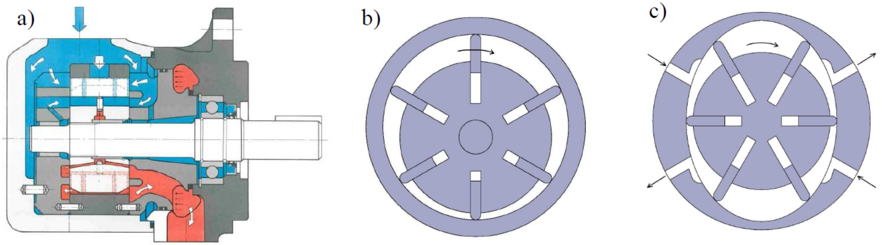
Vane pumps belong to the group of displacement machines in which the displacement elements are vanes placed in the radial slots of the rotor. The inter-vane volume changes depending on the angle of rotation and the working fluid is transported from the suction to the delivery channels.
There are two types of vane pumps, i.e., single-acting and double-acting (balanced) pumps (Figure 1). In double-acting pumps, during one rotation of the rotor, the suction and discharge cycles occur twice during one revolution.
Double -acting pumps have advantages such as: low bearing loads due to the compensation of pressure forces [2,3] and the associated higher maximum pressure, as well as high durability, low noise emission, and relatively high energy efficiency. Vane pumps are widely used due to their simple design and relatively easy manufacturing technology.
In conventional hydraulic drive solutions, the fluid flow is usually controlled by means of proportional valves and servo valves. Apart from the high price, electrohydraulic control systems have a number of disadvantages, including problems with stability at high loads and high sensitivity to contamination of the working fluid [4,5]. Due to the mechatronic pump drive, it would be possible to control its flow rate directly by varying the speed of the electric motor, which is a significant simplification of control systems in hydraulic drives.
The paper concerns a new design solution in Figure 5 which a displacement pump is built into the rotor of the electric motor [6,7]. The stator of the electric motor is a fixed element of the housing of the entire device. The rotor of the electric motor causes the displacement pump housing to rotate. The inner part of the pump (with the vanes) is stationary. Due to the lack of centrifugal forces, the vanes are pressed against the cam ring by springs [8].
In the case of currently used solutions, where the pump together with the casing and the motor are separate elements, a mounting console and a clutch are usually needed. These elements constitute an additional mass. In the integrated motor-pump assembly (IMPA) solution, these elements are not not present.
The authors are convinced that the advantages of this solution will include, above all, a higher power density in a volume unit compared to conventional solutions, the ability to control the pump flow rate by changing the rotational speed of the electric motor (hence better controllability), greater energy efficiency, better dynamics, and lower noise emissions due to the installation of positive displacement pump inside the electric motor, which is a kind of soundproofing housing. Such systems are more efficient due to the possibility of direct adjustment of the motor power consumption to the load of the actuators (actuator, hydraulic motor).
A similar solution has been used in Voith’s company EPAI pump [9]. In this solution, the internal gear pump is built into the interior of a three-phase, four-pole, squirrel cage induction motor with internal cooling with hydraulic fluid.
Despite the many types of electric motors available on the market, three-phase squirrel cage induction motors are the most widely used source of electric drive [10,11]. This is due to their simple construction, high reliability, low price, and low maintenance requirements. However, their efficiency, especially for low-rated power, is much lower compared to permanent magnet motors [10,11,12].
Permanent magnet motors are used in high-performance drives with a wide range of rotational speed regulation. They have the highest energy efficiency of all electric motors, the highest rated and maximum torque values per unit of mass and volume, and high torque overload [12,13]. Moreover, they enable high dynamics [14] and precision of the drive control, i.e., fast response of the drive to load changes and changes in control settings. They are widely used in automation and robotics [12,13,15], computer equipment [12], aviation [12,16,17,18], and electric and hybrid vehicles [12,19,20,21,22,23,24,25,26,27]. They are also used in medical devices [28,29,30,31] as well as in aerospace devices [12,32,33].
Due to the advantages of machines with permanent magnets, as a motor in the developed solution, a brushless DC motor with a rotational speed regulated by a converter was used. While, for example, in the publication of [34], solutions in which the pump is driven by brushless DC motors are known, the developed construction in which the vane pump is built into the rotor of the BLDC motor (Figure 2 and Figure 3) is a novel design solution.
In the further part of the article, the novel integrated motor-pump assembly is presented, as well as its experimental investigation on the designed and built test stand in the steady and dynamic states.
2. Design of the Novel Pump-Motor Assembly
The BLDC motor of the developed IMPA solution has been designed at the Department of Electrical Machines, Drives and Measurements of the Wrocław University of Science and Technology for the possibility of integrating a vane pump, and in order to obtain the required parameters: power of Pmax = 2.5 kW at the maximum rotational speed nmax = 3000 rpm.
Preliminary design calculations for the motor have been performed using the proprietary BLDC motor design program. With its help, the winding and initial dimensions of the magnetic circuit of the motor were selected. To reduce motor dimensions, a three-pole pairs construction has been applied. Then, using the ANSYS Maxwell software, a finite element method computational analysis of the influence of the motor magnetic circuit dimensions on the value of the magnetic flux, the cogging torque, the electromagnetic torque, the magnetic flux penetration into the pump, and the resistance of the magnets to demagnetization have been performed. The results of these computations made it possible to select the final motor design solution. In the ANSYS Maxwell software, using the developed field-circuit model of the: supply network—converter—motor system [35], the motor parameters were determined and then verified by measurements [36,37].
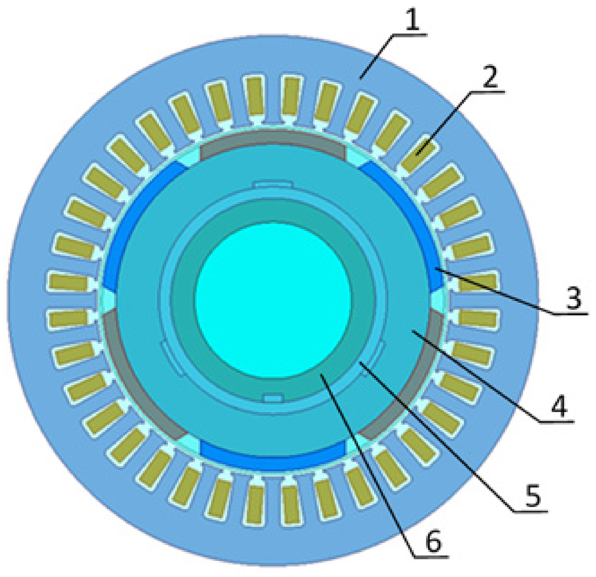
The cross-section of the motor magnetic circuit is shown in Figure 2. The stator consists of a laminated core (1) with a three-phase winding (2). High-energy neodymium magnets (3) are mounted on the rotor yoke surface (4). Between the rotor yoke (4) and the pump (6), a nonmagnetic bushing (5) is used. Its purpose is to prevent the penetration of the magnetic flux into the pump interior.
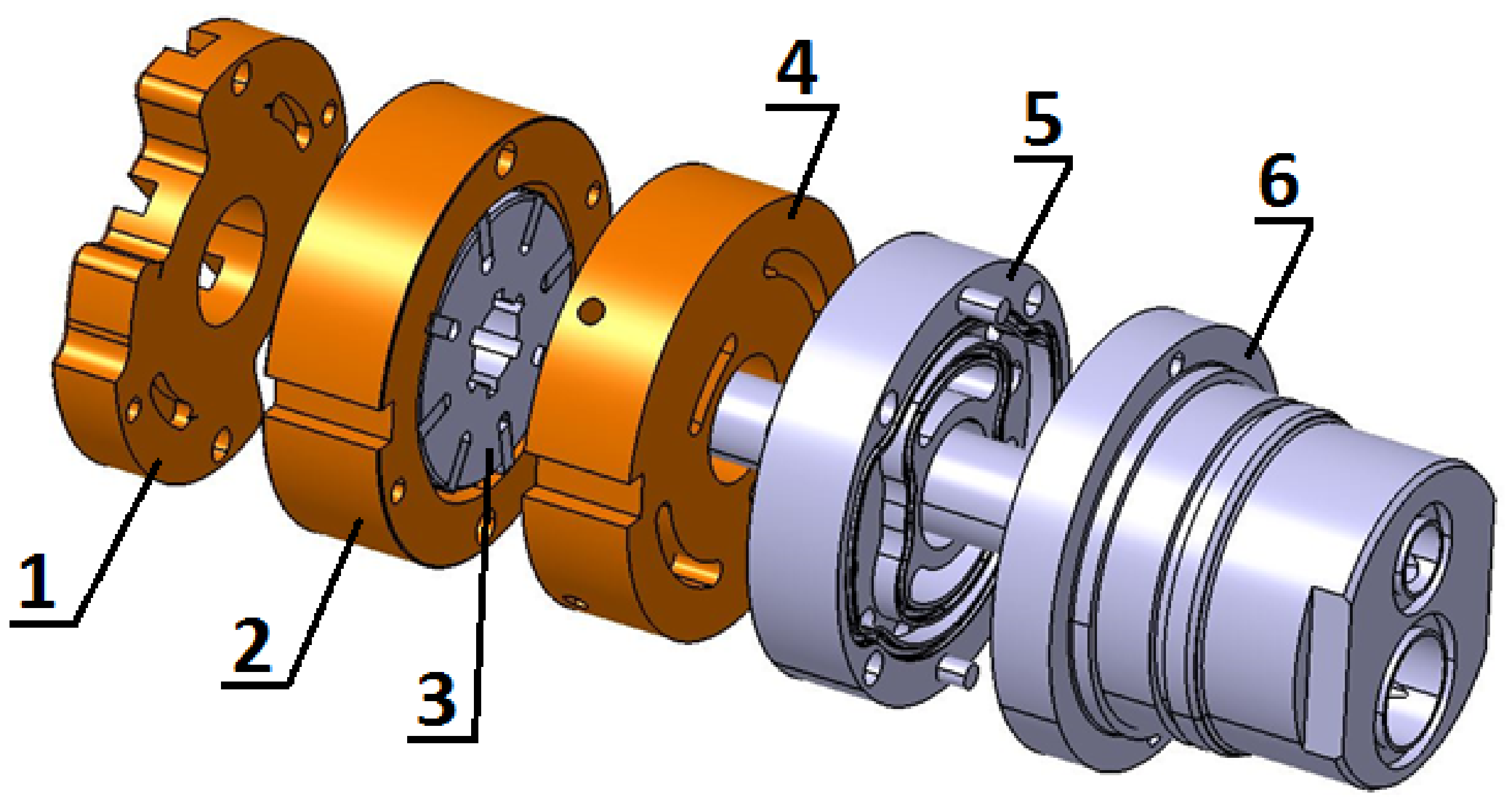
In Figure 3, the developed vane pump module is shown. The pump elements 1, 2 and 4 are movable, while the elements 3, 5 and 6 are stationary. The connection to the suction and delivery line occurs with the pressure compensated plate 5 and the connecting part 6 with the suction and discharge channels. Several problems had to be overcome through the different stages of the vane pump design process. One of the important issues was to select the geometry of the cross-over areas between the suction and discharge ports and to provide sufficient support for the vanes in these areas.
In the proposed integrated motor-pump assembly solution (Figure 4 and Figure 5), the pump cartridge 3 (Figure 4) is placed inside the rotor of the permanent magnet brushless DC motor (Figure 2, Figure 4 and Figure 5).
The rotor 5 of the motor (Figure 5) and the pump cartridge 8 (cam ring and two pressure plates) are coupled together. In the new solution, internal part of the pump 4 with vanes is stationary, therefore, the additional support of vanes with springs has been introduced.
The rotor 5 of the brushless DC motor (Figure 5) drives the pump cartridge 8. Due to the fact that the inner part 4 of the balanced vane pump is stationary, the vanes are pressed to a cam ring with spring elements. Changing the motor speed using the pulse width modulation method provides the ability to control the pump flow.
The developed IMPA solution has been patented (displacement pump with the integrated electric drive P. 213898), and is predestined for applications where the drive must be compact (weight reduction) and have reduced noise emissions. One of the possible application examples can be an electric driven vehicle with hydraulic ramp for lifting loads. The electric motor would then be powered by the battery of the vehicle.
3. Description of the Research Test Bench
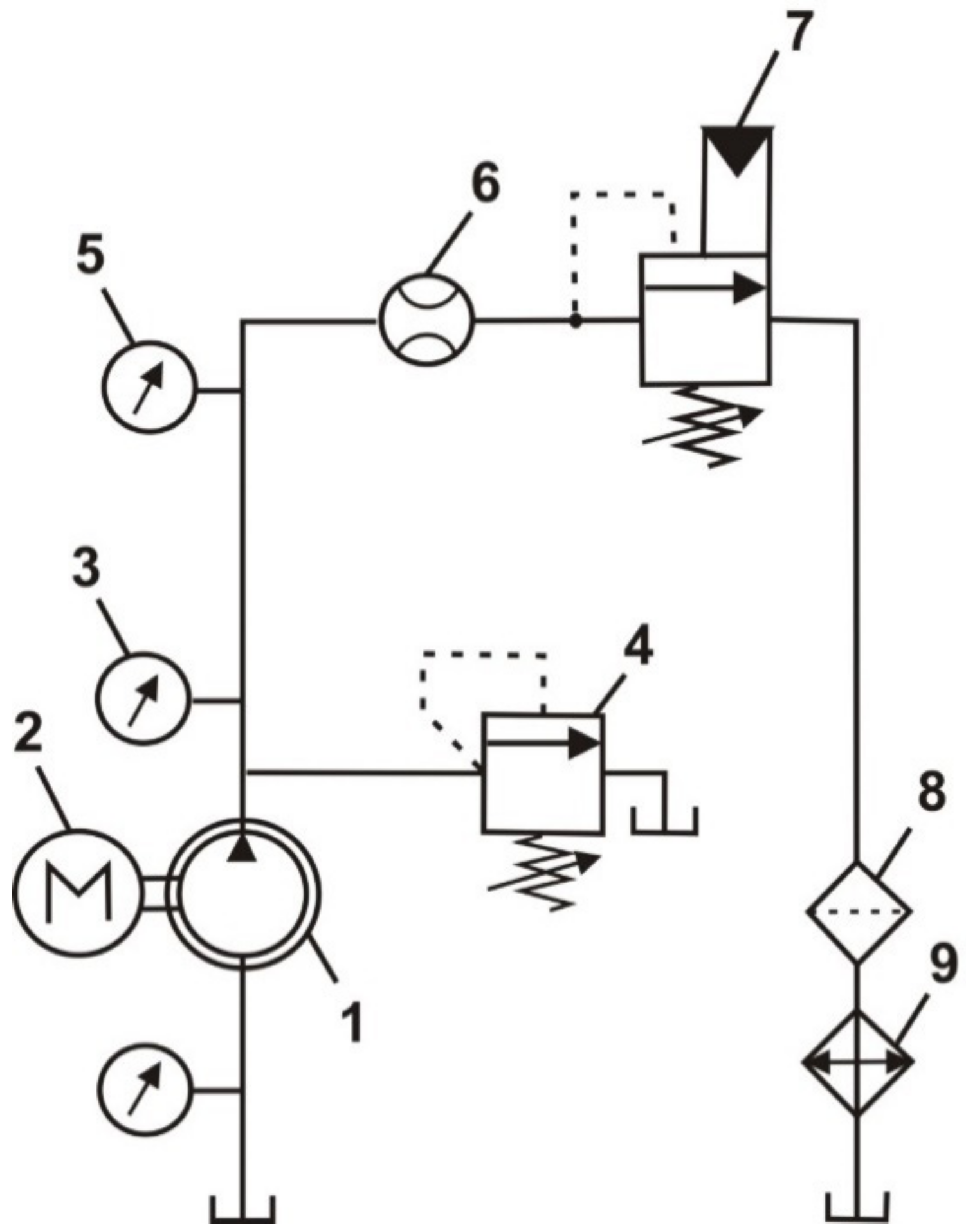
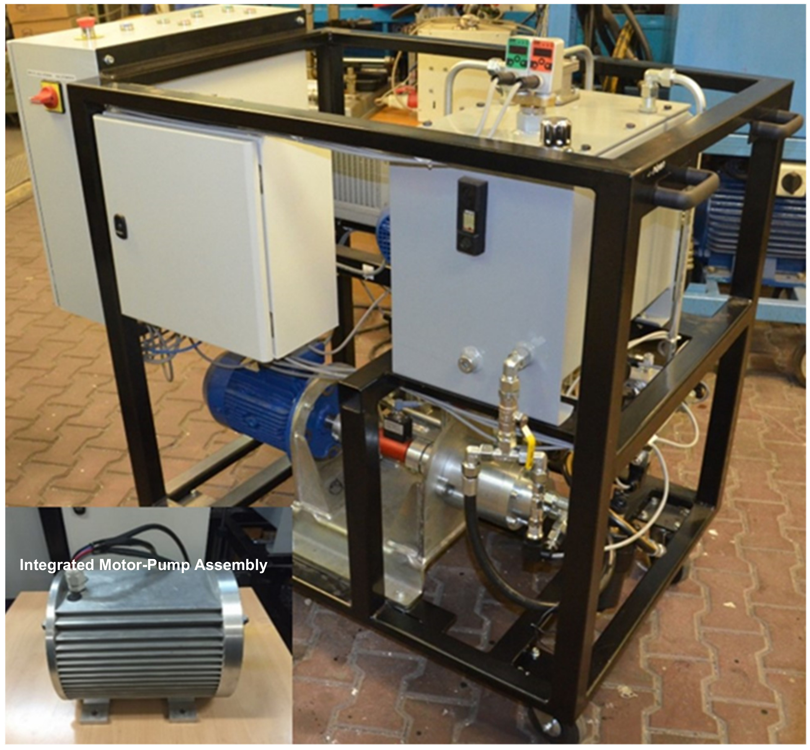
The research bench (Figure 6, Figure 7, Figure 8 and Figure 9) enables the measurement of electrical, mechanical, and hydraulic quantities in the system: power supply—converter—integrated motor pump assembly—hydraulic system, at different pressures in the hydraulic system, and at different speeds.
Absolute pressure (5), pressure pulsation (3), and flow rate (6) are measured on the delivery side of the pump (Figure 6). On the return line, the filter (8) and cooler (9) are located. The load of the pump is realized by the proportional pressure relief valve (7). The safety valve (4) secures the system maximal pressure.
The Parker SCP 400 pressure transducer (3) with the 0–400 bar measuring range and accuracy of 0.5% has been used. The SCFT-060 turbine flow rate meter (6) is from Parker (measuring range: 3–60 Lpm, measured value accuracy +/− 0.5%). The oil temperature is controlled using a temperature sensor.
The test bench and the developed integrated motor-pump assembly unit are shown in Figure 7.
The BLDC motor is powered (Figure 8) by a converter (rectifier—capacitor—inverter) from a single-phase 230 VAC, 50 Hz mains. The measurement-control panel (Figure 8 and Figure 9) contains rms and average value meters, current transducers as well as switching and signalling elements.
LA55-P transducers have been used to measure phase currents, and a differential probe has been applied for the purpose of measuring voltages.
The instantaneous values of motor speed, currents and voltages, as well as the converter supply voltage and current, are given to the PCI-6123 multifunction DAQ device and PC through the BNC-2110 terminal block (Figure 8). Information about the position of the rotor as well as the speed signal are obtained by means of optical sensors.
The rotational speed of the IMPA may be controlled manually by the control panel potentiometer or by setting the value or trajectory of the speed control signal by the LabVIEW program. The virtual instrument developed in the LabVIEW programming environment provides communication with the DAQ card, previewing, and registering of the measured hydraulic, electrical, and mechanical signals.
4. Steady-State Tests of the Motor-Pump Assembly
Measurements of the waveforms of electrical and hydraulic quantities in steady states have been performed at different values of speed stabilized by the converter. The sampling frequency of electrical quantity signals was set to the maximum value supported by the measurement card at 500,000 samples per second per channel. Such a high sampling frequency of electrical signals resulted from the pulse width modulation (PWM) of the converter supplying the motor pump unit with the 15,625 Hz frequency. The sampling rate of the hydraulic quantities was 100 samples/s.
The results for speeds of 1000 rpm and 1500 rpm at the pressure of 60 bar are presented in Figure 10, Figure 11, Figure 12 and Figure 13.
The waveforms of the converter input current and voltage are presented in Figure 10.
The converter input current is not continuous. It is taken from the supply network in the time periods in which the instantaneous value of the voltage at the input of the converter is higher than the voltage of capacitor C (Figure 8). The frequency of the capacitor voltage pulsation, i.e., the voltage at the input of the inverter, is 100 Hz.
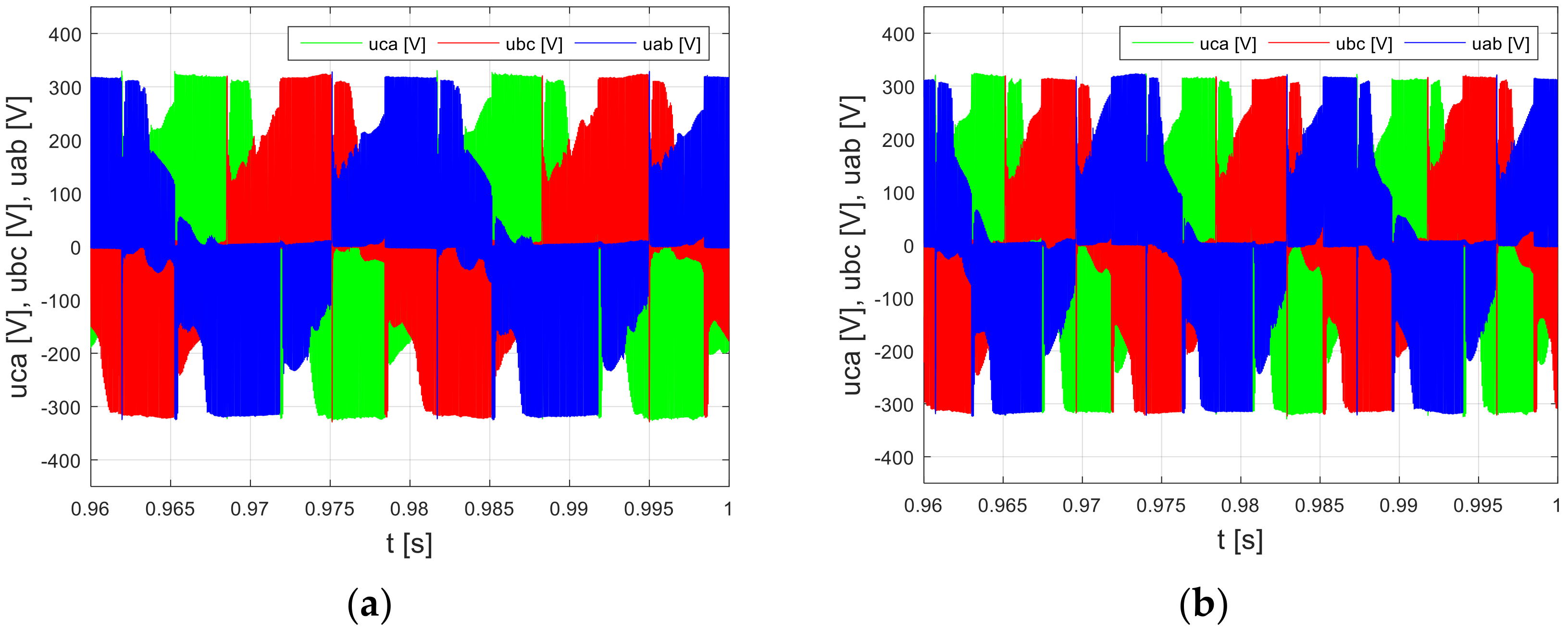
Pulsations of this voltage are transferred to the waveforms of the phase-to-phase voltages (Figure 11) and phase currents (Figure 12) of the motor. They are more noticeable, the higher the output power of the motor-pump unit.
Apart from pulsations with a frequency of 100 Hz, the waveforms of phase-to-phase voltages and phase currents also contain pulsations resulting from the pulse width modulation (PWM) operation of the inverter and from the commutation of the phase windings.
In the waveforms of the motor phase currents, the share of pulsations resulting from the commutation is the highest.
Similarly to the phase-to-phase voltages (Figure 11), differences can be noticed for different rotational speeds in the phase currents’ (Figure 12) commutation frequency. This is due to the operation of the converter which supplies the winding phases on the basis of information about the rotor position.
Pulsations in the waveforms of electrical quantities (currents and voltages) and the resulting pulsations of the mechanical torque of the motor practically do not cause the pulsation of rotational speed. The rotational speed ripples do not exceed 2%, which is due to the high frequency of mechanical torque pulsations, the rotor moment of inertia, and the operation of the converter speed stabilization system.
The pump flow rate at 60 bar pressure for the speed of 1000 and 1500 rpm is shown in Figure 13.
5. Dynamic Testing of the Motor-Pump Assembly at Constant Rotational Speed and Pressure Changes
Measurements of electrical and hydraulic quantities’ waveforms have been performed at different values of speed (1000, 1500 rpm) stabilized by the converter while forcing pressure changes with the use of the proportional solenoid valve.
Changes in the pressure waveforms were forced by the LabVIEW program by setting the voltage signal trajectory that controls the operation of the proportional solenoid valve. These waveforms corresponded to a typical “ramp” function, i.e., the valve control signal increased linearly in the initial time interval, then it was kept constant, and in the final phase, it decreased linearly.
The waveform of the given voltage signal controlling the solenoid valve is shown in Figure 14. The ramp time (signal rise and fall time) was one second.
The performed tests showed that the converter input voltage and the motor phase-to-phase voltages practically did not change with pressure changes, and therefore they were not included in the article. This proves that the converter and the motor can be loaded with more power than that required by the hydraulic system during the measurements.
The converter input currents for the speeds of 1000 and 1500 rpm are presented, respectively, in Figure 15, while the phase currents of the motor-pump assembly are shown in Figure 16.
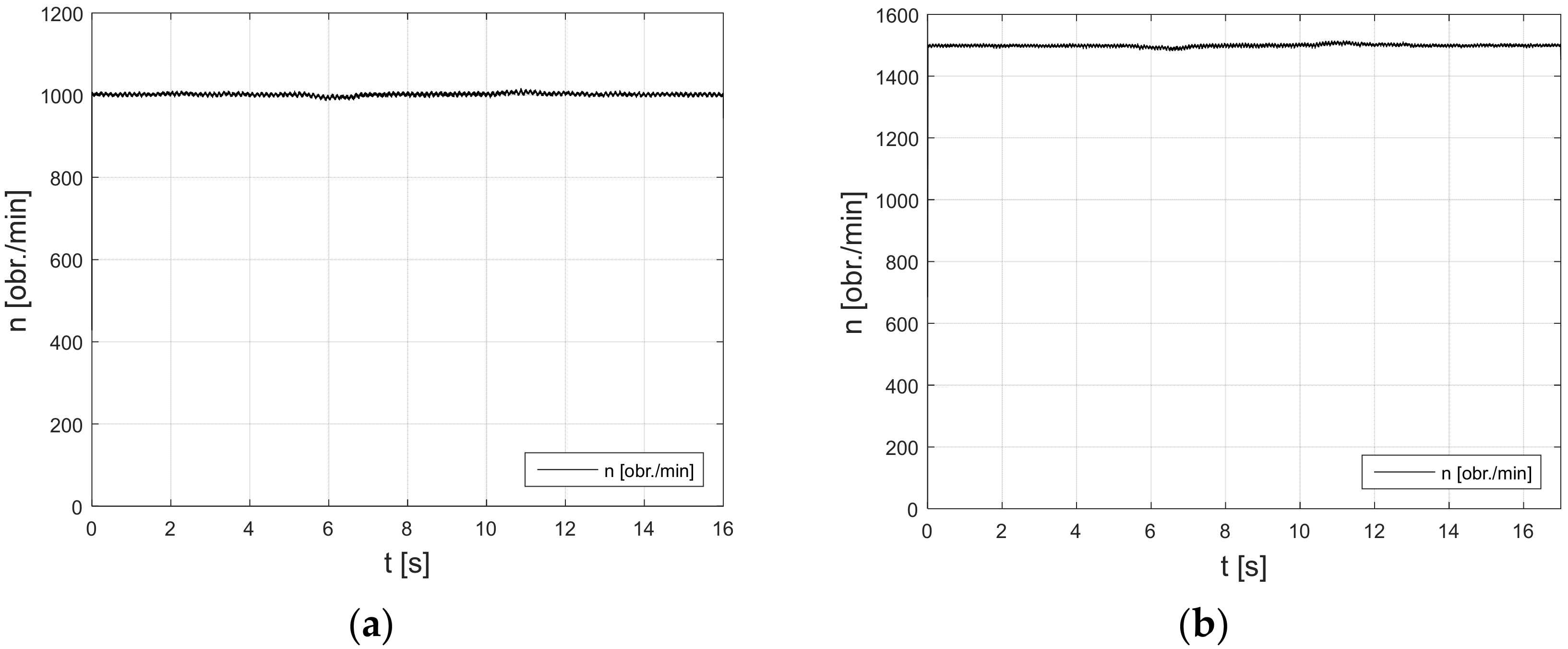
During the pressure changes in the hydraulic system (Figure 17), the rotational speed (Figure 18) practically did not change. At the speed of 1000 rpm, the speed changes did not exceed 1.4%, while at the speed of 1500 rpm, the changes were less than 1.1%. This proves a good quality stabilization of the rotational speed of the motor-pump drive system.
The drive system reacts without delay and overshoot to load changes caused by pressure changes in the hydraulic system. This results from a comparison of the waveforms of the converter input current (Figure 15), the phase currents of the motor-pump assembly (Figure 16), the waveforms of the actual pressure changes (Figure 17), and the pump flow rate (Figure 19). This proves the good dynamics of the pump drive system. However, the discharge pressure variation occurred with a significant delay from the LabVIEW voltage control signal (Figure 14 and Figure 17).
The tests have confirmed the good quality of the pump drive system control. During pressure changes, there were no excesses, which usually occur with this type of change in the hydraulic system.
6. Dynamic Testing of the Motor-Pump Assembly at Constant Pressure and Changes in the Rotational Speed
Measurements of the waveforms of electrical and hydraulic quantities of the motor pump unit in dynamic states at different changes of rotational speed were performed. Measurements have been carried out without the voltage signal controlling the pressure in the hydraulic system. The sampling frequency of the electrical quantity signals was 500,000 samples/s and the sampling frequency of the hydraulic quantity signals was 100 samples/s. The changes in rotational speed were set manually by means of the converter.
The waveforms of rotational speed changes are presented in Figure 20. The measured waveforms of the electrical and hydraulic quantities of the motor-pump unit at various rotational speed changes are presented in Figure 21, Figure 22 and Figure 23.
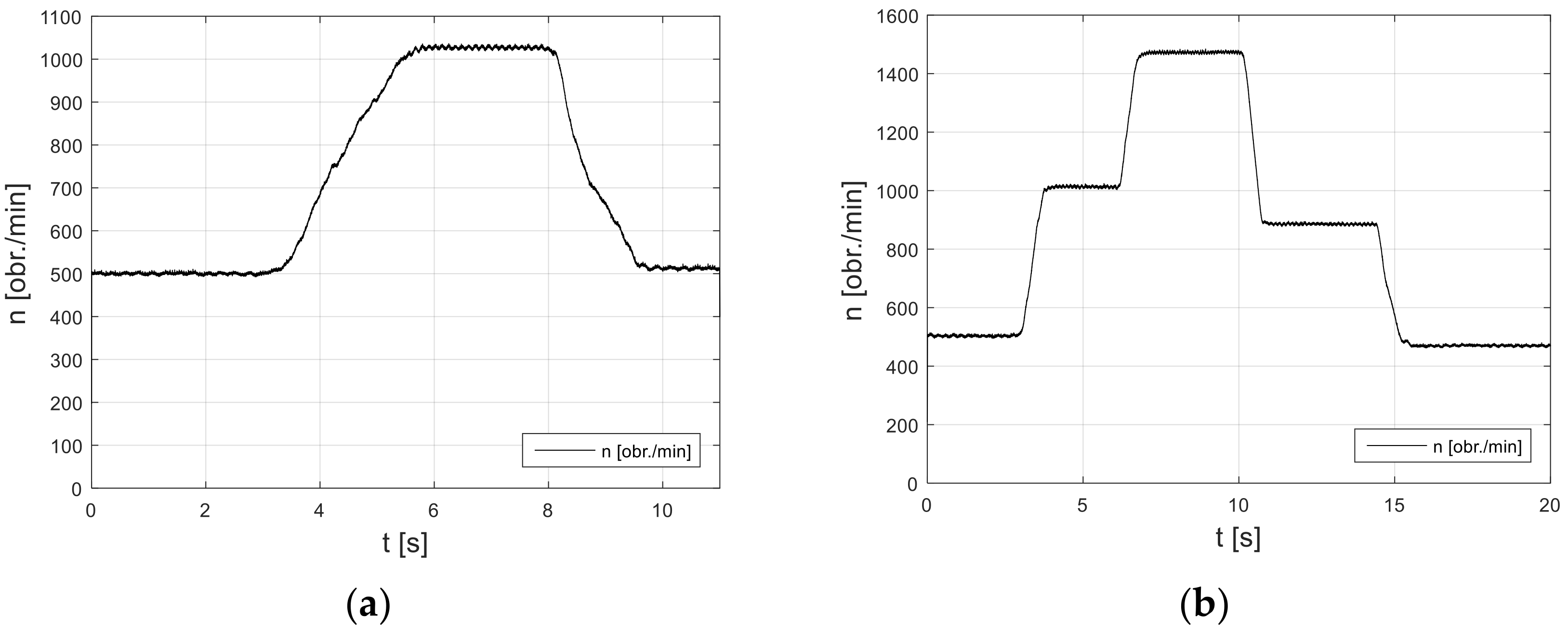
Variations in the rotational speed of the motor (Figure 20) lead to the corresponding changes in the flow rate of the pump. By changing the rotational speed of the electric motor, it is possible to control the pump flow rate and thus the speed of the hydraulic cylinder or the speed of the hydraulic motor. The control of the speed of the electric motor has a high dynamic, comparable to that of control by means of hydraulic valves. During the changes in rotational speed, no overshoots, usually accompanying such changes in the hydraulic system, were observed.
7. Conclusions
The integrated motor-pump assembly has been tested at different speeds of the pump and different pressures in the hydraulic system. The measured waveforms of electrical quantities (current and voltage at the converter input, motor phase currents, and phase-to-phase voltages) are correct, i.e., characteristic for a drive system with a brushless DC motor and with the PWM speed control. The tests have shown good dynamics of the developed integrated motor-pump assembly and proved its suitability to control the pump flow rate and thus the speed of the hydraulic cylinder or the speed of the hydraulic motor.
8. Patents
Displacement pump with the integrated electric drive P. 213898.
Author Contributions
Conceptualization, M.P.C. and W.F.; methodology, M.P.C. and W.F.; software, M.P.C. and W.F.; validation, M.P.C. and W.F.; formal analysis, M.P.C. and W.F.; investigation, M.P.C. and W.F.; resources, M.P.C. and W.F.; data curation, M.P.C. and W.F.; writing—original draft preparation, M.P.C. and W.F.; writing—review and editing, M.P.C. and W.F.; visualization, M.P.C. and W.F.; supervision, M.P.C. and W.F. Both authors have read and agreed to the published version of the manuscript.
Funding
This research was funded by The Polish National Centre of Research and Development, grant number 208471.
Conflicts of Interest
The authors declare no conflict of interest.
References
- Ivantysyn, J.; Ivantysynova, M. Hydrostatic Pumps and Motors: Principles, Design, Performance, Modelling, Analysis, Control and Testing; Tech Books International: New Delhi, India, 2003. [Google Scholar]
- Brusiani, F.; Bianchi, G.; Costa, M.; Squarcini, R.; Gasperini, M. Analysis of Air/Cavitation Interaction inside a Rotary Vane Pump for Application on Heavy Duty Engine; SAE Technical Paper 2009-01-1943; SAE International: Warrendale, PA, USA, 2009. [Google Scholar]
- Sullivan, P.; Sehmby, M. Internal Force Analysis of a Variable Displacement Vane Pump; SAE Technical Paper 2012-01-0409; SAE International: Warrendale, PA, USA, 2012. [Google Scholar] [CrossRef]
- Frendo, F.; Novi, N.; Squarcini, R. Numerical and Experimental Analysis of Variable Displacement Vane Pumps. In Proceedings of the International Conference on Tribology, Parma, Italy, 20–22 September 2006. [Google Scholar]
- Inaguma, Y. Friction Characteristics of Vane for a Balanced Vane Pump. Trans. Jpn. Fluid Power Syst. Soc. 2014, 45, 58–65. [Google Scholar] [CrossRef] [Green Version]
- Fiebig, W.; Cependa, P.; Jędraszczyk, P.; Kuczwara, H. Innovative Solution of an Integrated Motor Pump Assembly. In Fluid Power Systems Technology; American Society of Mechanical Engineers: New York, NY, USA, 2017. [Google Scholar]
- Fiebig, W.; Dudzikowski, I.; Ciurys, M.; Hubert, K. A Vane Pump Integrated with an Electric Motor. In Proceedings of the 9th International Fluid Power Conference, IFK, Aachen, Germany, 9 March 2014. [Google Scholar]
- Fiebig, W.; Cependa, P.; Kuczwara, H.; Wang, F. Analysis of vane loads and motion in a hydraulic double vane pump with integrated electrical drive. Arch. Civ. Mech. Eng. 2021, 21, 1–15. [Google Scholar] [CrossRef]
- Motor/Pump Hybrid System EPAI for High and Medium- Pressure Application; Voith Brochure: Rutesheim, Germany, 2012.
- Almeida, A.; Ferreira, F.J.T.E.; Fong, J. Standards for Efficiency of Electric Motors. IEEE Ind. Appl. Mag. 2011, 17, 12–19. [Google Scholar] [CrossRef]
- De Almeida, A.T.; Ferreira, F.J.T.E.; Baoming, G. Beyond Induction Motors—Technology Trends to Move Up Efficiency. IEEE Trans. Ind. Appl. 2014, 50, 2103–2114. [Google Scholar] [CrossRef]
- Gieras, J.F. Permanent Magnet Motor Technology: Design and Applications, 3rd ed.; CRC Press: Boca Raton, FL, USA, 2009; ISBN 978-1-4200-6440-7. [Google Scholar]
- Hendershot, J.R.; Miller, T.J.E. Design of Brushless Permanent-Magnet Machines, 2nd ed.; Motor Design Books LLC: Venice, FL, USA, 2010; ISBN 978-0-9840687-0-8. [Google Scholar]
- Hughes, A. Electric Motors and Drives: Fundamentals, Types and Applications, 3rd ed.; Newnes: Amsterdam, NY, USA; Boston, MA, USA, 2006; ISBN 978-0-7506-4718-2. [Google Scholar]
- Seo, J.-M.; Rhyu, S.-H.; Kim, J.-H.; Choi, J.-H.; Jung, I.-S. Design of Axial Flux Permanent Magnet Brushless DC Motor for Robot Joint Module. In Proceedings of the 2010 International Power Electronics Conference ECCE ASIA, Sapporo, Japan, 21–24 June 2010; pp. 1336–1340. [Google Scholar]
- Yang, S.; Jung, Y.; Seo, J.; Lee, M.; Kim, J.-H. Numerical and Experimental Study on the Cooling Performance Affected by Ventilation Holes of a BLDC Motor for Multi-Copters. In Proceedings of the 2018 IEEE 18th International Power Electronics and Motion Control Conference, Budapest, Hungary, 26–30 August 2018; pp. 293–298. [Google Scholar] [CrossRef]
- Cao, W.; Mecrow, B.C.; Atkinson, G.J.; Bennett, J.W.; Atkinson, D.J. Overview of Electric Motor Technologies Used for More Electric Aircraft (MEA). IEEE Trans. Ind. Electron. 2012, 59, 3523–3531. [Google Scholar] [CrossRef]
- Carev, V.; Roháč, J.; Šipoš, M.; Schmirler, M. A Multilayer Brushless DC Motor for Heavy Lift Drones. Energies 2021, 14, 2504. [Google Scholar] [CrossRef]
- Chau, K.T.; Chan, C.C.; Liu, C. Overview of Permanent-Magnet Brushless Drives for Electric and Hybrid Electric Vehicles. IEEE Trans. Ind. Electron. 2008, 55, 2246–2257. [Google Scholar] [CrossRef] [Green Version]
- Liu, X.; Chen, H.; Zhao, J.; Belahcen, A. Research on the Performances and Parameters of Interior PMSM Used for Electric Vehicles. IEEE Trans. Ind. Electron. 2016, 63, 3533–3545. [Google Scholar] [CrossRef]
- Pellegrino, G.; Vagati, A.; Guglielmi, P.; Boazzo, B. Performance Comparison between Surface-Mounted and Interior PM Motor Drives for Electric Vehicle Application. IEEE Trans. Ind. Electron. 2011, 59, 803–811. [Google Scholar] [CrossRef] [Green Version]
- De Santiago, J.; Bernhoff, H.; Ekergård, B.; Eriksson, S.; Ferhatovic, S.; Waters, R.; Leijon, M. Electrical Motor Drivelines in Commercial All-Electric Vehicles: A Review. IEEE Trans. Veh. Technol. 2012, 61, 475–484. [Google Scholar] [CrossRef] [Green Version]
- Wang, J.; Yuan, X.; Atallah, K. Design Optimization of a Surface-Mounted Permanent-Magnet Motor with Concentrated Windings for Electric Vehicle Applications. IEEE Trans. Veh. Technol. 2013, 62, 1053–1064. [Google Scholar] [CrossRef]
- Yang, Z.; Shang, F.; Brown, I.P.; Krishnamurthy, M. Comparative Study of Interior Permanent Magnet, Induction, and Switched Reluctance Motor Drives for EV and HEV Applications. IEEE Trans. Transp. Electrif. 2015, 1, 245–254. [Google Scholar] [CrossRef]
- Yang, Y.-P.; Luh, Y.-P.; Cheung, C.-H. Design and Control of Axial-Flux Brushless DC Wheel Motors for Electric Vehicles—Part I: Multiobjective Optimal Design and Analysis. IEEE Trans. Magn. 2004, 40, 1873–1882. [Google Scholar] [CrossRef]
- Zeraoulia, M.; Benbouzid, M.E.H.; Diallo, D. Electric Motor Drive Selection Issues for HEV Propulsion Systems: A Comparative Study. IEEE Trans. Veh. Technol. 2006, 55, 1756–1764. [Google Scholar] [CrossRef] [Green Version]
- Xu, W.; Zhu, J.; Guo, Y.; Wang, S.; Wang, Y.; Shi, Z. Survey on Electrical Machines in Electrical Vehicles. In Proceedings of the 2009 International Conference on Applied Superconductivity and Electromagnetic Devices, Chengdu, China, 25–27 September 2009; pp. 167–170. [Google Scholar]
- Antaki, J.; Paden, B.; Piovoso, M.; Banda, S. Award-winning control applications. IEEE Control. Syst. Mag. 2002, 22, 8–19. [Google Scholar] [CrossRef]
- Piccigallo, M.; Scarfogliero, U.; Quaglia, C.; Petroni, G.; Valdastri, P.; Menciassi, A.; Dario, P. Design of a Novel Bimanual Robotic System for Single-Port Laparoscopy. IEEE/ASME Trans. Mechatron. 2010, 15, 871–878. [Google Scholar] [CrossRef] [Green Version]
- Lawson, B.E.; Mitchell, J.E.; Truex, D.; Shultz, A.H.; LeDoux, E.; Goldfarb, M. A Robotic Leg Prosthesis: Design, Control, and Implementation. IEEE Robot. Autom. Mag. 2014, 21, 70–81. [Google Scholar] [CrossRef]
- Yamashita, H.; Kim, D.; Hata, N.; Dohi, T. Multi-Slider Linkage Mechanism for Endoscopic Forceps Manipulator. In Proceedings of the 2003 IEEE/RSJ International Conference on Intelligent Robots and Systems (IROS 2003) (Cat. No.03CH37453), Las Vegas, NV, USA, 27–31 October 2003; Volume 3, pp. 2577–2582. [Google Scholar]
- Li, H.; Li, W.; Ren, H. Fault-Tolerant Inverter for High-Speed Low-Inductance BLDC Drives in Aerospace Applications. IEEE Trans. Power Electron. 2017, 32, 2452–2463. [Google Scholar] [CrossRef]
- Huang, X.; Goodman, A.; Gerada, C.; Fang, Y.; Lu, Q. Design of a Five-Phase Brushless DC Motor for a Safety Critical Aerospace Application. IEEE Trans. Ind. Electron. 2012, 59, 3532–3541. [Google Scholar] [CrossRef]
- Yoon, K.-Y.; Baek, S.-W. Robust Design Optimization with Penalty Function for Electric Oil Pumps with BLDC Motors. Energies 2019, 12, 153. [Google Scholar] [CrossRef] [Green Version]
- Ciurys, M.P. Electromagnetic phenomena analysis in brushless DC motor with speed control using PWM method. Open Phys. 2017, 15, 907–912. [Google Scholar] [CrossRef] [Green Version]
- Ciurys, M.P. Analysis of the Influence of Inverter PWM Speed Control Methods on the Operation of a BLDC Motor. Arch. Electr. Eng. 2018, 67, 939–953. [Google Scholar] [CrossRef]
- Ciurys, M.P.; Dudzikowski, I.; Pawlak, M. Laboratory tests of a PM-BLDC motor drive. In Proceedings of the 2015 Selected Problems of Electrical Engineering and Electronics (WZEE), Kielce, Poland, 17–19 September 2015; pp. 1–6. [Google Scholar] [CrossRef]
Figure 1.
The vane pump: (a) Cross-over; (b) Single-acting; (c) Double-acting.

Figure 2.
Cross-section of the brushless DC motor. 1—stator core, 2—winding, 3—permanent magnet, 4—rotor yoke, 5—non-magnetic sleeve, 6—pump.
Figure 2.
Cross-section of the brushless DC motor. 1—stator core, 2—winding, 3—permanent magnet, 4—rotor yoke, 5—non-magnetic sleeve, 6—pump.

Figure 3.
Vane pump module [6]. (Copyright by ASME, 2017) Number of vanes 8, unit displacement 3.45 cm3/rev. 1—left pressure plate, 2—cam ring, 3—internal part of the pump with vanes, 4—right pressure plate/rotational part of the flow distributor, 5—stationary part of the flow distributor, 6—delivery channels.

Figure 4.
Vane pump integrated with BLDC motor. 1—stator, 2—rotor of electric motor, 3—pump cartridge.
Figure 4.
Vane pump integrated with BLDC motor. 1—stator, 2—rotor of electric motor, 3—pump cartridge.
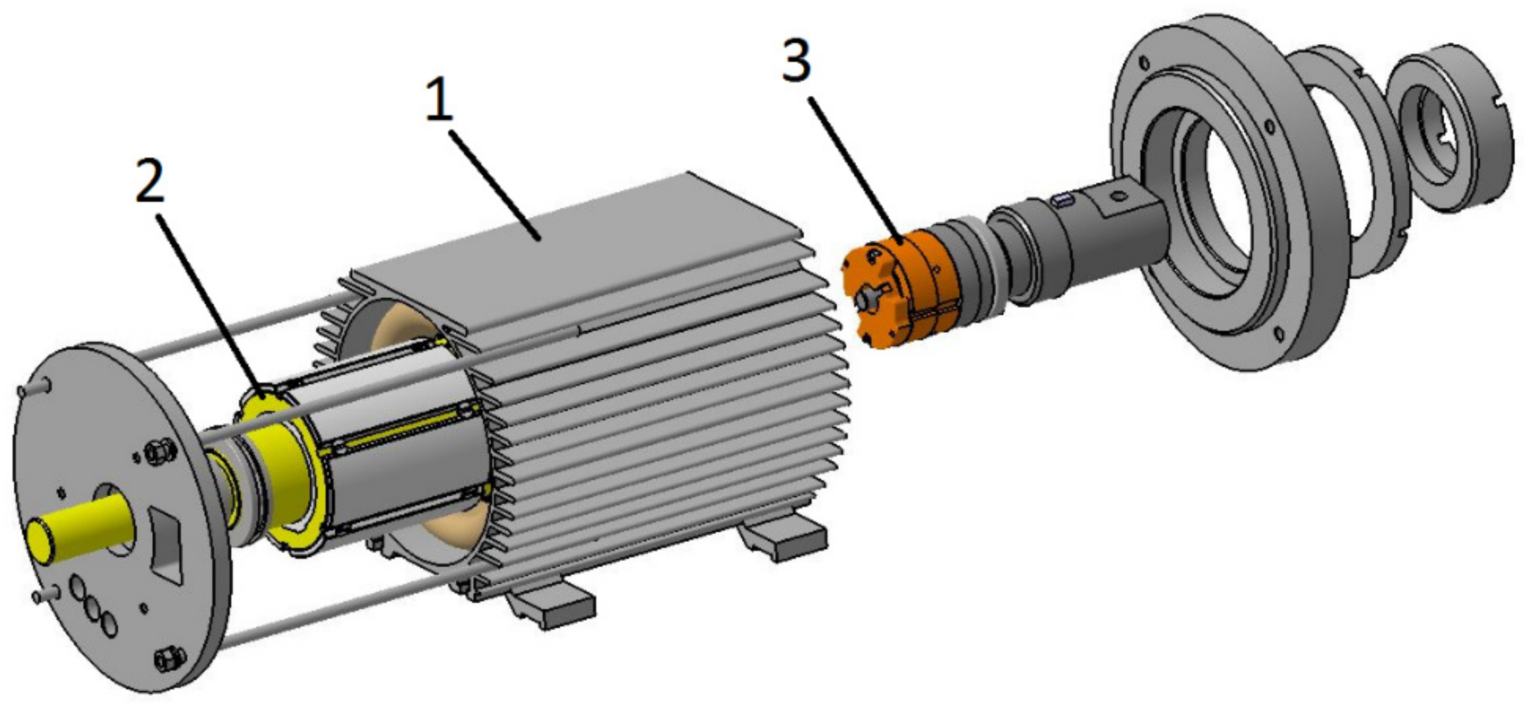
Figure 5.
Integrated BLDC motor-vane pump assembly. 1—stator core, 2—covers, 3—suction and discharge channels, 4—internal part with vanes, 5—rotor of brushless DC motor, 6—nonmagnetic bushing, 7—neodymium magnets, 8—pump cartridge [6]. (Copyright by ASME, 2017).
Figure 5.
Integrated BLDC motor-vane pump assembly. 1—stator core, 2—covers, 3—suction and discharge channels, 4—internal part with vanes, 5—rotor of brushless DC motor, 6—nonmagnetic bushing, 7—neodymium magnets, 8—pump cartridge [6]. (Copyright by ASME, 2017).
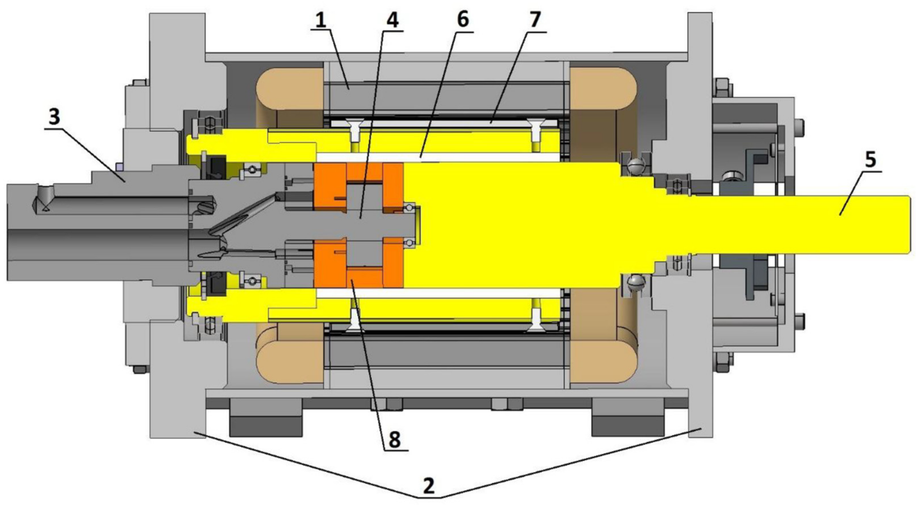
Figure 6.
The schematic view of the hydraulic test rig. 1, 2—pump motor assembly, 3, 5—pressure gauge, 4—pressure relief valve, 6—flow meter, 7—pressure relief valve, 8—filter, 9–cooler.
Figure 6.
The schematic view of the hydraulic test rig. 1, 2—pump motor assembly, 3, 5—pressure gauge, 4—pressure relief valve, 6—flow meter, 7—pressure relief valve, 8—filter, 9–cooler.

Figure 7.
View of the test bench.

Figure 8.
Diagram of the system for measuring electrical quantities of the motor-pump unit. is— converter current, us—supply voltage, ia, ib, ic—phase currents, va, vb, vc—potentials of the phases a, b, and c, uac, ubc—line-to-line voltages, and n—speed.
Figure 8.
Diagram of the system for measuring electrical quantities of the motor-pump unit. is— converter current, us—supply voltage, ia, ib, ic—phase currents, va, vb, vc—potentials of the phases a, b, and c, uac, ubc—line-to-line voltages, and n—speed.
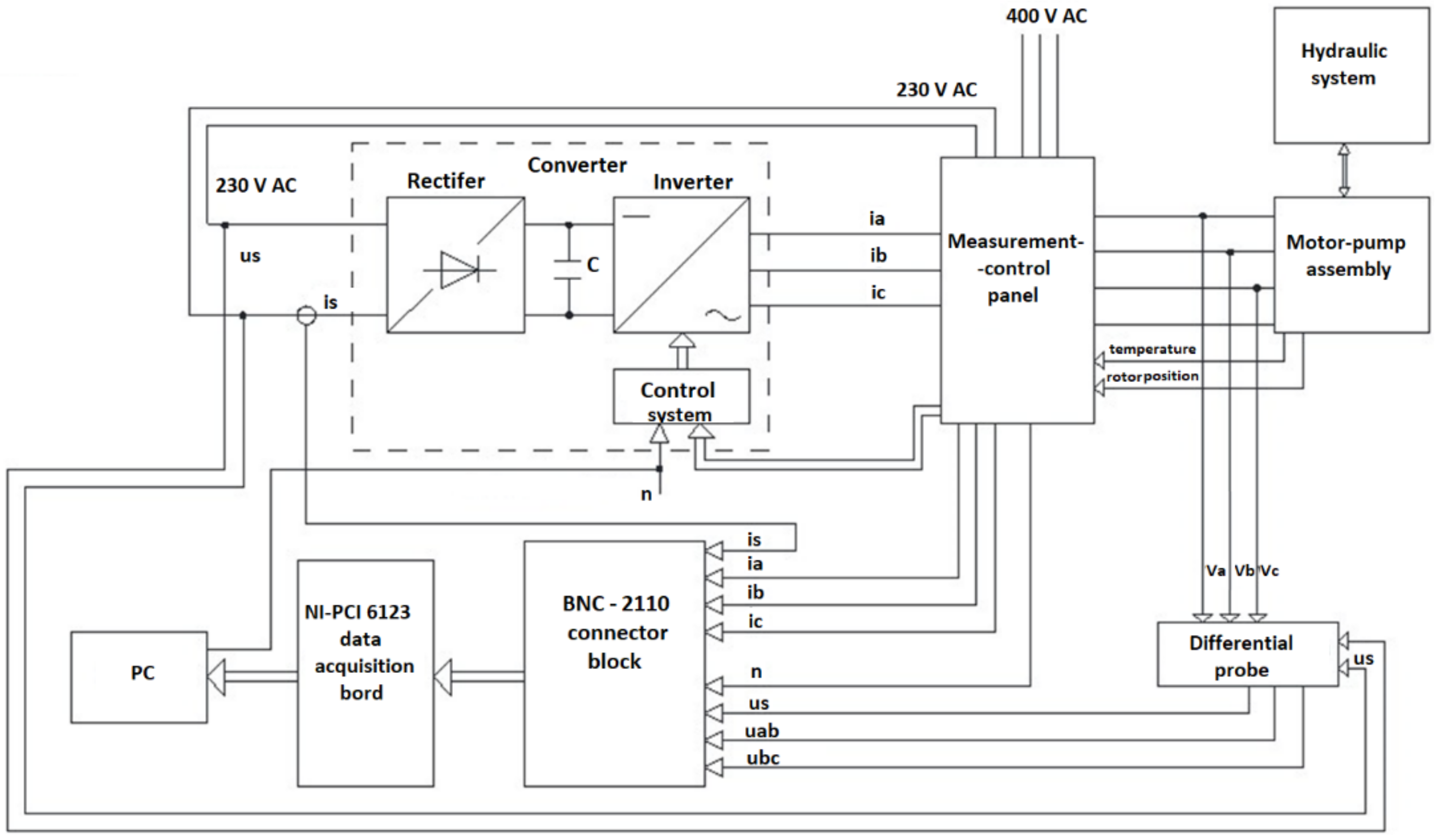
Figure 9.
View of the system elements for measuring electrical quantities of the motor-pump unit. 1—measurement-control panel, 2—converter, 3—differential probe, 4—BNC-2110 connector block.
Figure 9.
View of the system elements for measuring electrical quantities of the motor-pump unit. 1—measurement-control panel, 2—converter, 3—differential probe, 4—BNC-2110 connector block.

Figure 10.
Waveforms of the converter input current (is) and voltage (us) at the 60 bar pressure for the speed of: (a) 1000 rpm; (b) 1500 rpm.
Figure 10.
Waveforms of the converter input current (is) and voltage (us) at the 60 bar pressure for the speed of: (a) 1000 rpm; (b) 1500 rpm.
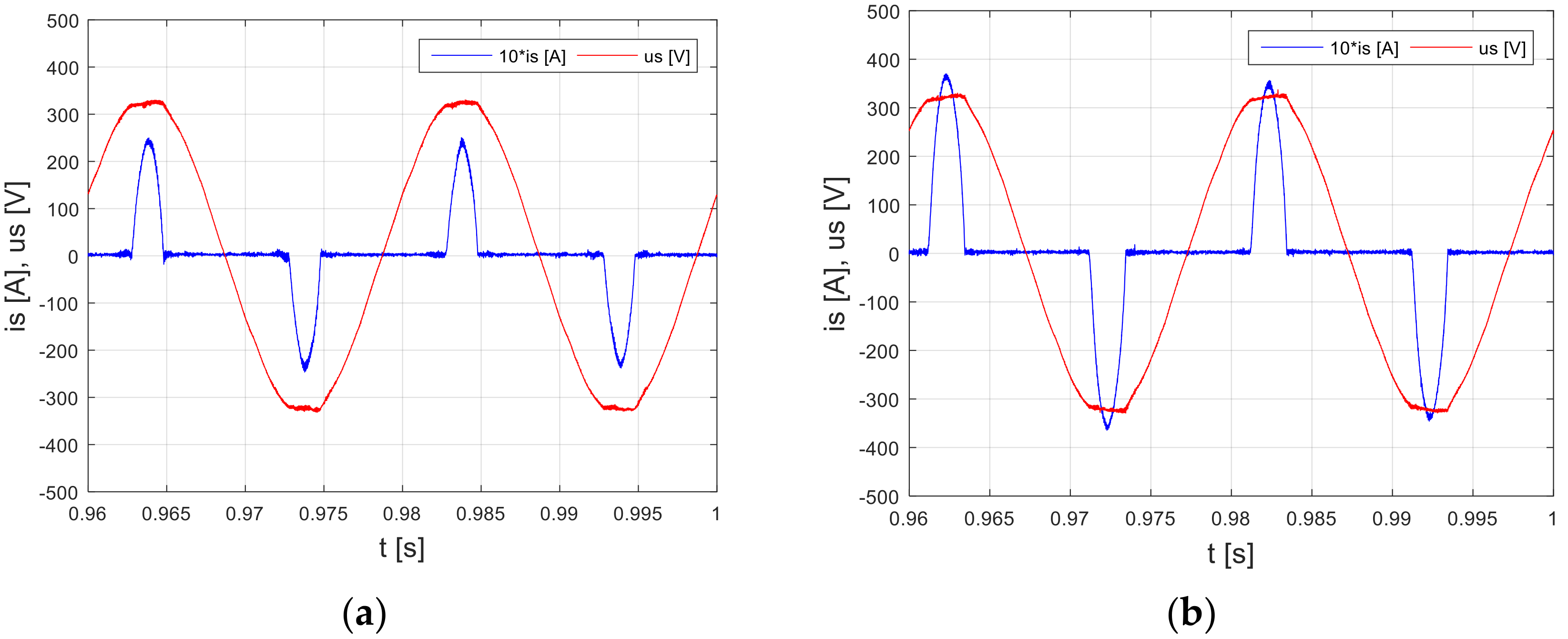
Figure 11.
Waveforms of the line-to-line voltages (uab, ubc, uca) at 60 bar pressure for the speed of: (a) 1000 rpm; (b) 1500 rpm.
Figure 11.
Waveforms of the line-to-line voltages (uab, ubc, uca) at 60 bar pressure for the speed of: (a) 1000 rpm; (b) 1500 rpm.

Figure 12.
Phase-current waveforms (ia, ib, ic) at the 60 bar pressure for the speed of: (a) 1000 rpm; (b) 1500 rpm.
Figure 12.
Phase-current waveforms (ia, ib, ic) at the 60 bar pressure for the speed of: (a) 1000 rpm; (b) 1500 rpm.

Figure 13.
Waveforms of the pump flow rate (Q) at 60 bar pressure for the speed of: (a) 1000 rpm; (b) 1500 rpm.
Figure 13.
Waveforms of the pump flow rate (Q) at 60 bar pressure for the speed of: (a) 1000 rpm; (b) 1500 rpm.
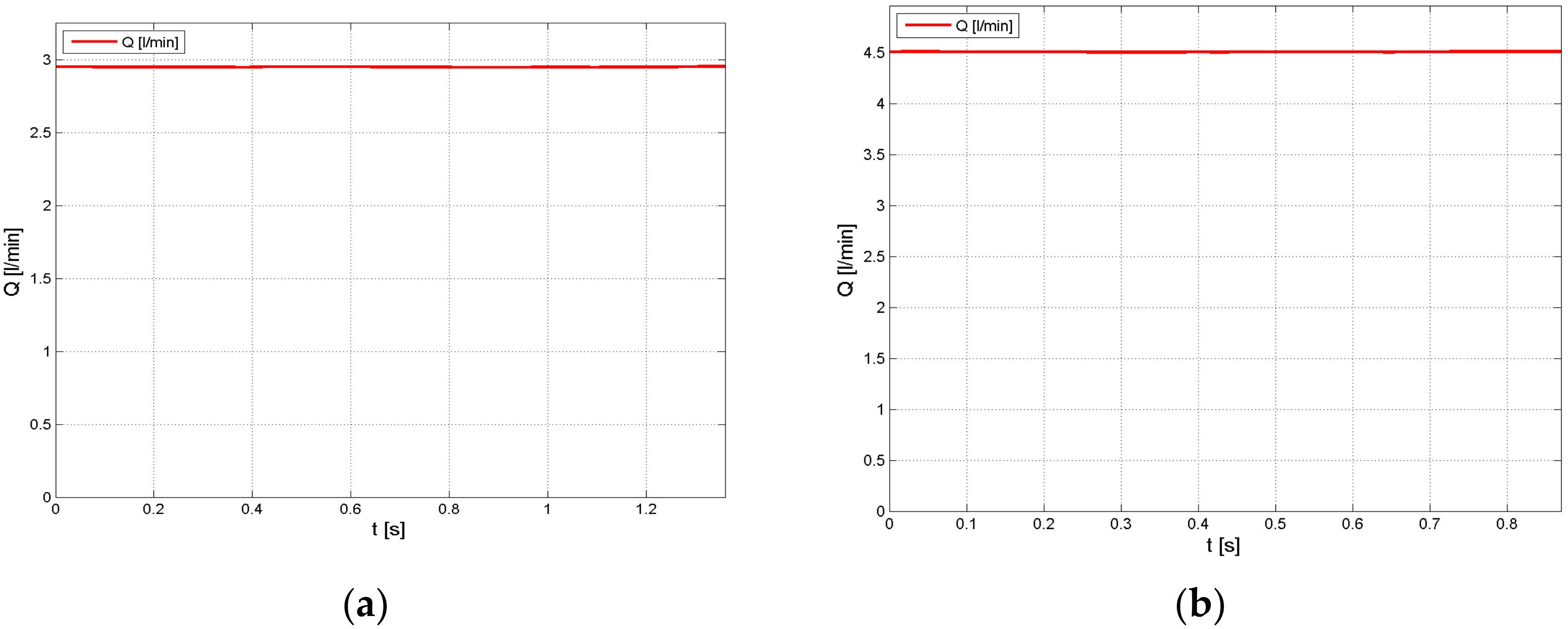
Figure 14.
Waveform of the control signal.

Figure 15.
Waveforms of the input current of the converter for the speed of: (a) 1000 rpm; (b) 1500 rpm.
Figure 15.
Waveforms of the input current of the converter for the speed of: (a) 1000 rpm; (b) 1500 rpm.
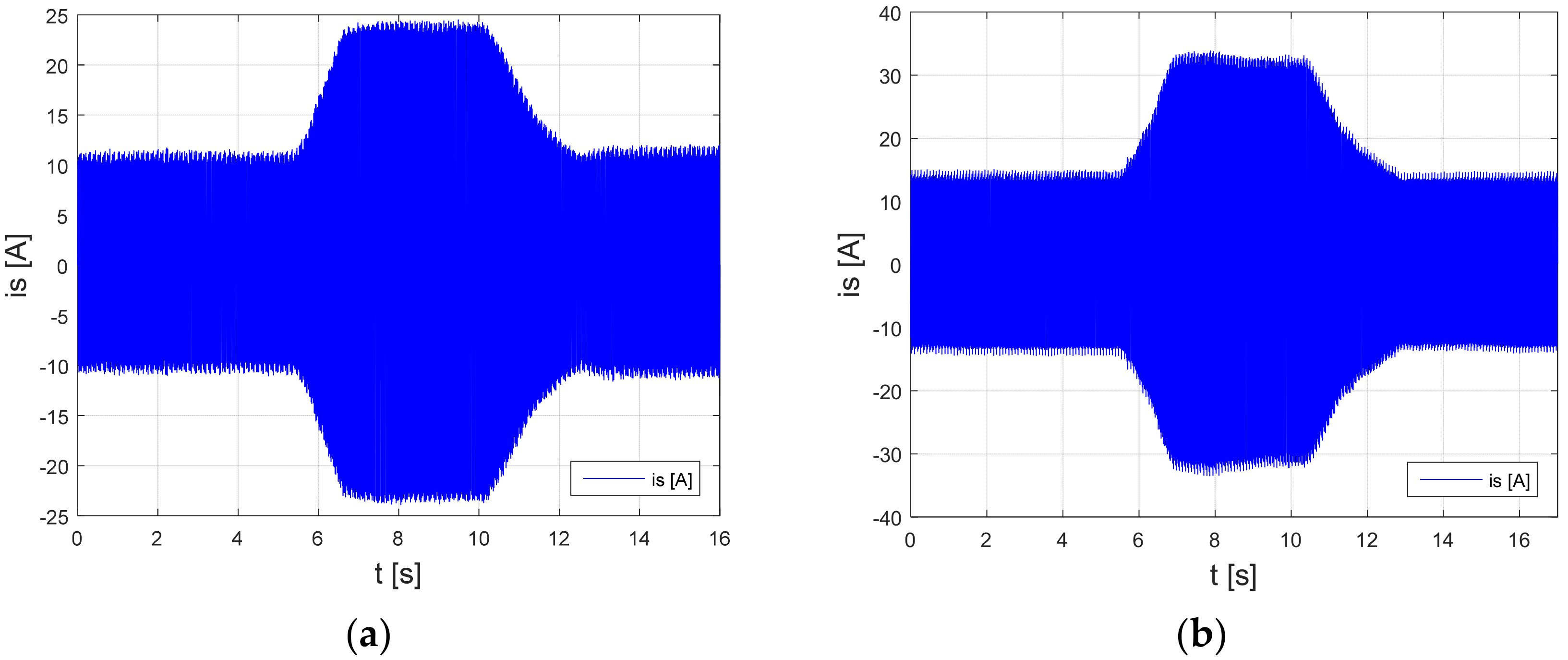
Figure 16.
Phase-current waveforms (ia, ib, ic) for the speed of: (a) 1000 rpm; (b) 1500 rpm.
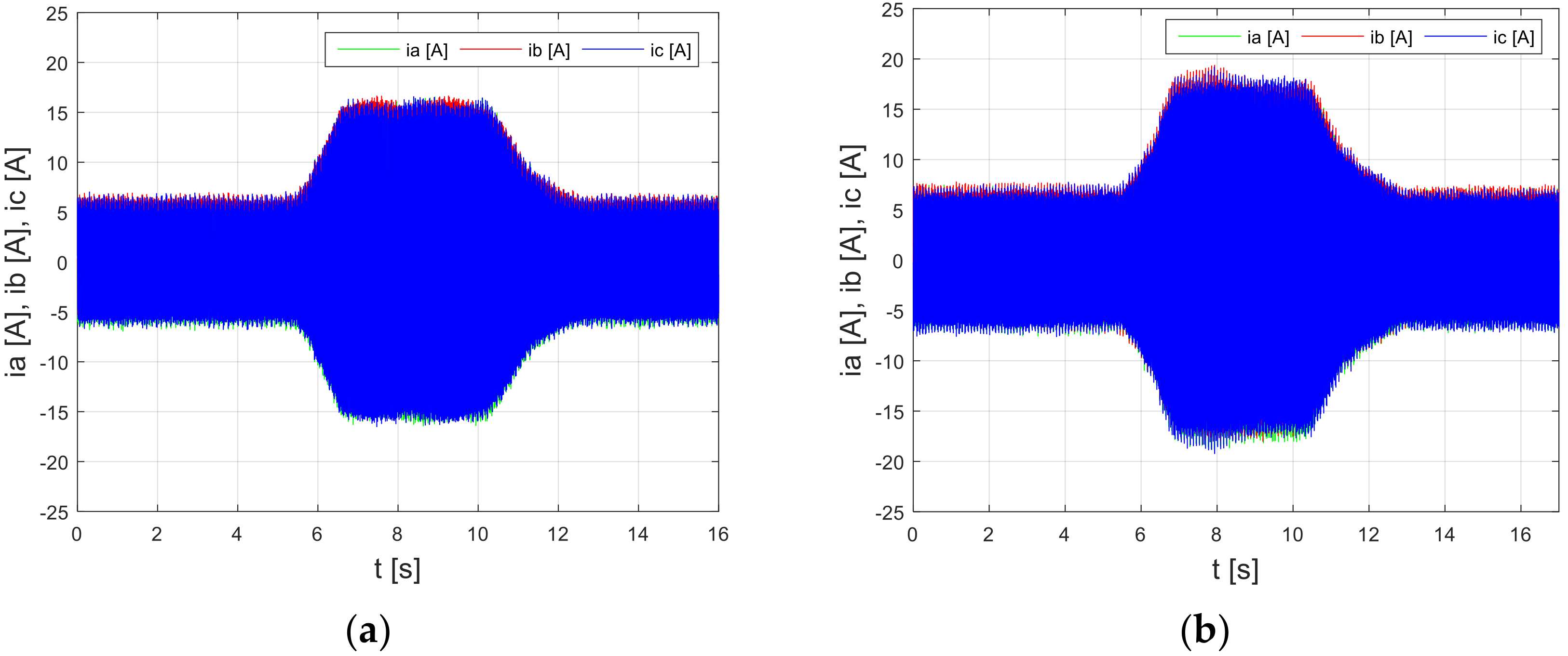
Figure 17.
Waveforms of the pressure (Pp) for the speed of: (a) 1000 rpm; (b) 1500 rpm.
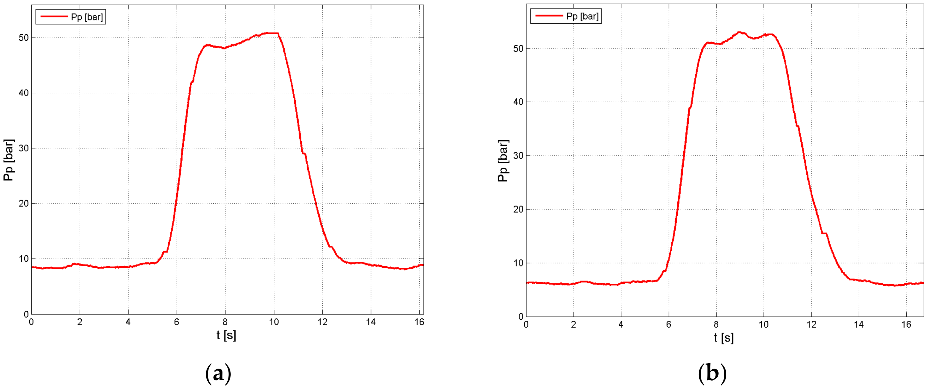
Figure 18.
Waveforms of rotational speed (n) for the speed of: (a) 1000 rpm; (b) 1500 rpm.

Figure 19.
Waveforms of the pump flow rate (Q) for the speed of: (a) 1000 rpm; (b) 1500 rpm.
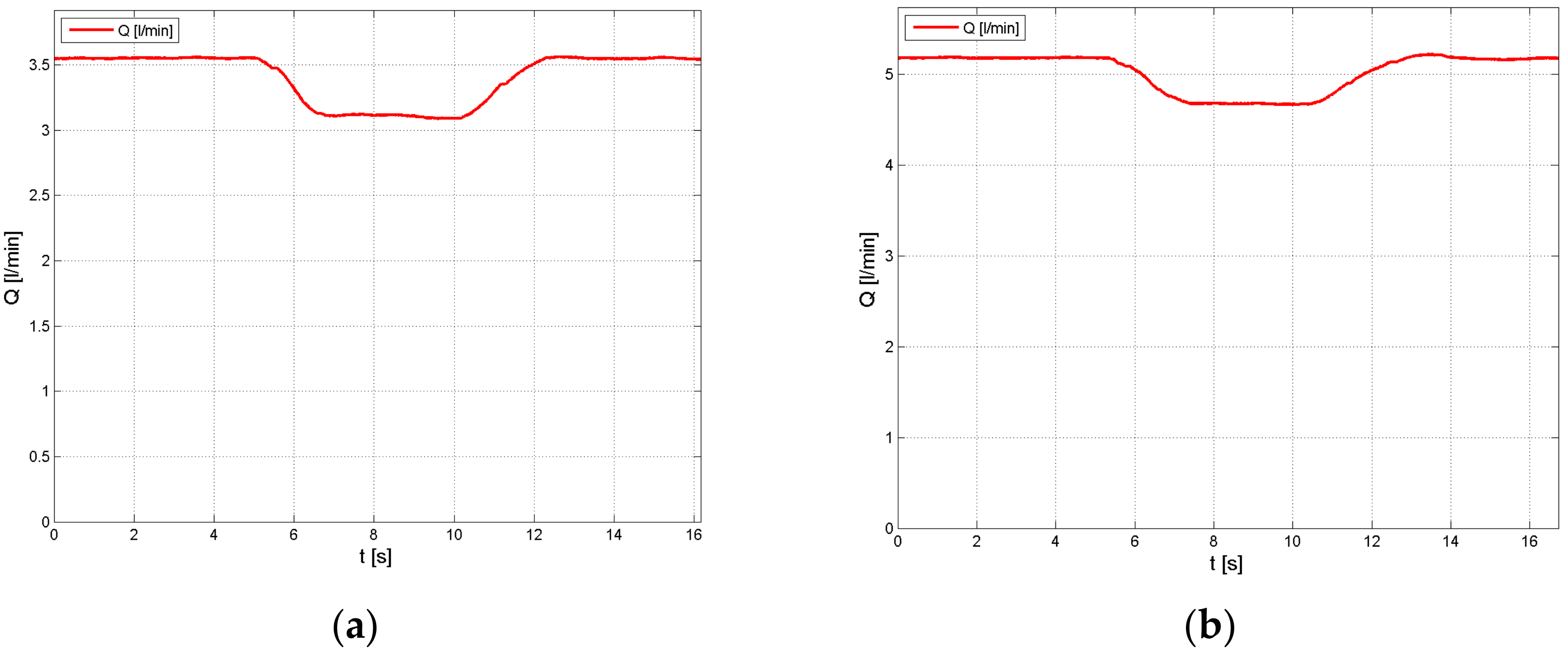
Figure 20.
Waveforms of the forced rotational speed changes of the motor-pump assembly: (a) Single speed ramp; (b) Double speed ramp.
Figure 20.
Waveforms of the forced rotational speed changes of the motor-pump assembly: (a) Single speed ramp; (b) Double speed ramp.

Figure 21.
Waveforms of the converter input current: (a) Single speed ramp; (b) Double speed ramp.
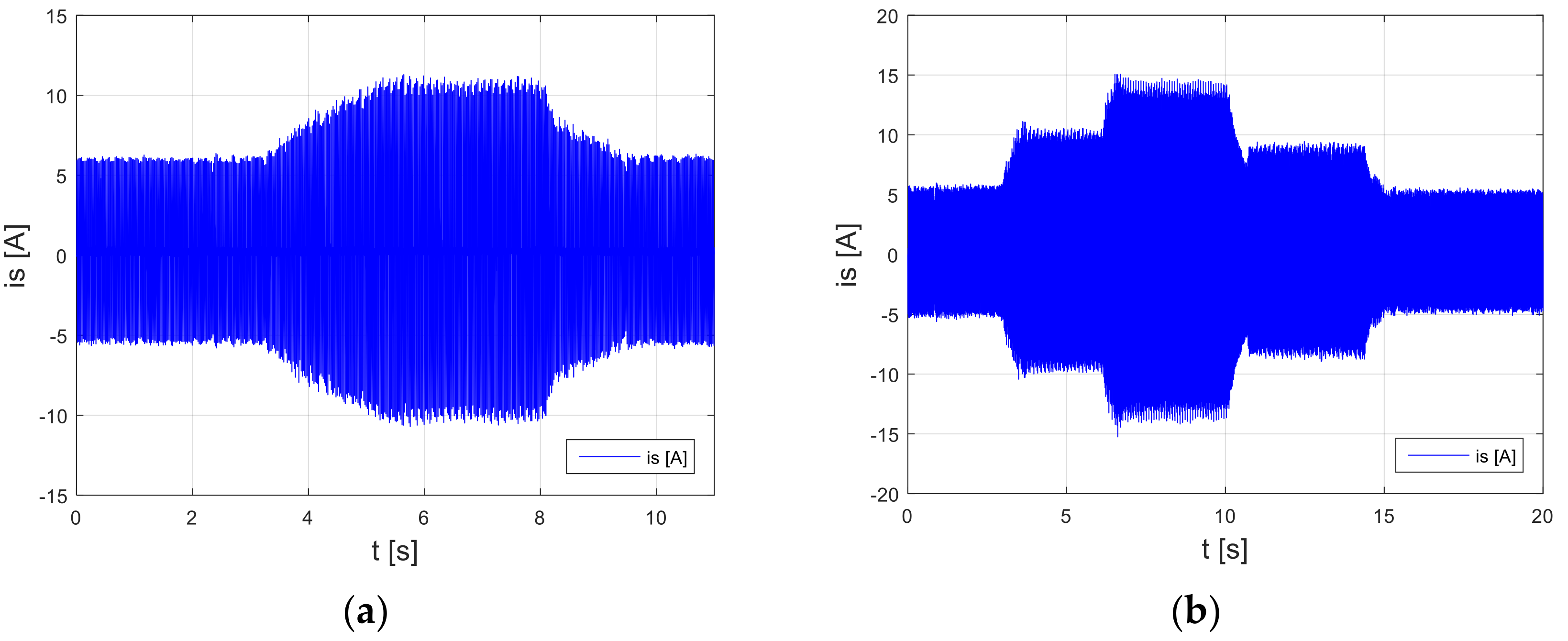
Figure 22.
Motor-pump assembly phase-current waveforms: (a) Single speed ramp; (b) Double speed ramp.
Figure 22.
Motor-pump assembly phase-current waveforms: (a) Single speed ramp; (b) Double speed ramp.

Figure 23.
Flow rate: (a) Single speed ramp; (b) Double speed ramp.

Publisher’s Note: MDPI stays neutral with regard to jurisdictional claims in published maps and institutional affiliations. |
© 2021 by the authors. Licensee MDPI, Basel, Switzerland. This article is an open access article distributed under the terms and conditions of the Creative Commons Attribution (CC BY) license (https://creativecommons.org/licenses/by/4.0/).
Share and Cite
MDPI and ACS Style
Ciurys, M.P.; Fiebig, W. Experimental Investigation of a Double-Acting Vane Pump with Integrated Electric Drive. Energies 2021, 14, 5949. https://doi.org/10.3390/en14185949
AMA Style
Ciurys MP, Fiebig W. Experimental Investigation of a Double-Acting Vane Pump with Integrated Electric Drive. Energies. 2021; 14(18):5949. https://doi.org/10.3390/en14185949
Chicago/Turabian StyleCiurys, Marek Pawel, and Wieslaw Fiebig. 2021. "Experimental Investigation of a Double-Acting Vane Pump with Integrated Electric Drive" Energies 14, no. 18: 5949. https://doi.org/10.3390/en14185949
Note that from the first issue of 2016, this journal uses article numbers instead of page numbers. See further details here.