
Design and Optimization of a High-Speed Switched Reluctance Motor

1
Department of Power Systems and Electric Drives, Faculty of Electrical Engineering and Information Technology, University of Zilina, 010 26 Žilina, Slovakia
2
Department of Design and Machine Elements, Faculty of Mechanical Engineering, University of Zilina, 010 26 Žilina, Slovakia
3
Department of Power Engineering, Faculty of Mechanical Engineering, University of Zilina, 010 26 Žilina, Slovakia
*
Author to whom correspondence should be addressed.
Energies 2021, 14(20), 6733; https://doi.org/10.3390/en14206733
Submission received: 18 August 2021
/
Revised: 8 October 2021
/
Accepted: 12 October 2021
/
Published: 16 October 2021
(This article belongs to the Special Issue Design and Application of Electrical Machines)
Abstract
:Currently, one of the most used motor types for high-speed applications is the permanent-magnet synchronous motor. However, this type of machine has high costs and rare earth elements are needed for its production. For these reasons, permanent-magnet-free alternatives are being sought. An overview of high-speed electrical machines has shown that the switched reluctance motor is a possible alternative. This paper deals with design and optimization of this motor, which should achieve the same output power as the existing high-speed permanent-magnet synchronous motor while maintaining the same motor volume. The paper presents the initial design of the motor and the procedure for analyses performed using analytical and finite element methods. During the electromagnetic analysis, the influence of motor geometric parameters on parameters such as: maximum current, average torque, torque ripple, output power, and losses was analyzed. The analysis of windage losses was performed by analytical calculation. Based on the results, it was necessary to create a cylindrical rotor shape. The rotor modification method was chosen based on mechanical analysis. Using thermal analysis, the design was modified to meet thermal limits. The result of the work was a design that met all requirements and limits.
1. Introduction
High-speed machines are used in an increasing number of applications, such as compressors, turbochargers, spindles, flywheel energy-storage systems, turbomolecular pumps, and microturbine generators. These machines are defined by rotational speed and frequency, but also the peripheral speed of the rotor, because this is dominant limitation in the design of these machines [1].
Higher rotational speed brings many advantages, such as reducing the volume of the machine while maintaining the same output power. The machine can be smaller and lighter, which is especially desirable in automotive applications in which any weight reduction leads to reduced fuel consumption and emissions. Another advantage in some applications is the elimination of the gearbox between the drive and the driven equipment, which leads to reduced costs and increased reliability [2].
The choice of the electrical machine type for high-speed application depends mainly on the specific application. In the past, universal motors were used. The advantage of these machines was especially their simple speed control, but the disadvantages were low efficiency and short commutator lifetime, which were associated with high maintenance costs [3]. Because of these disadvantages, they are currently being replaced by other types of electrical machines, including:
- Induction machines (IMs);
- Permanent-magnet synchronous machines (PMSMs); and
- Reluctance machines.
IMs with a laminated rotor are used in common industrial applications. For high-speed applications, their usage is significantly limited due to the high centrifugal forces acting on the squirrel cage. According to [4], it is a problem for them to work above 50,000 rpm. From a mechanical point of view, IMs with a solid rotor are more suitable for high-speed applications. According to the overview in [1], up to 180,000 rpm can be achieved with this type of IM. The disadvantages of these machines compared to PMSMs are a lower efficiency and higher rotor heating, which are caused by losses in the rotor winding [5].
Another type of electrical machine that has been the focus of many researchers is the PMSM. The advantages of this type of machine are especially high efficiency and smaller volume compared to IMs. The disadvantages are increased costs and the risk of PM demagnetization due to high temperatures and strong magnetic fields. In addition, these machines have high rotor inertia, which leads to higher bearing load and shortened bearing lifetime [6]. PMs can be located on the rotor surface (SPM) or inside (interior) the rotor (IPM). In the case of SPMs, PMs are fixed with a high-strength adhesive, and a sleeve is often required [7]. A comparison of these two topologies presented in [8] showed that from an electromagnetic point of view, higher iron losses occurred in the IPM topology. A disadvantage of IPM topology compared to the SPM is also higher susceptibility to mechanical damage. However, the cost of IPM topology is lower due to the smaller number of PMs needed to achieve the same output power. According to the overview in [1], the SPM rotor is used more frequently for high-speed machines. According to this article, PMSMs are preferred in applications with a higher speed and lower output power, and vice versa for IMs.
The rising price of rare earth elements has resulted in the search for an alternative to PMSMs without significantly affecting performance. Alternatively, reluctance machines can be used, including the switched reluctance motor (SRM) and reluctance synchronous motor (RSM). For high-speed applications, the SRM is mainly used. From the overview given in [9], the highest speed for which an RSM has been designed is 54,000 rpm.
An SRM has a simple and robust construction, formed by salient poles on the stator and rotor. The concentrated winding is wound around the stator poles. The individual winding coils can be prepared in advance and then slid onto the individual stator poles, which simplifies production and reduces costs. This winding also allows better heat dissipation, and since the end winding can be shorter compared to those in IMs, there is a decrease in winding losses [10]. The individual coils are connected in series or in parallel, and form phases that are gradually excited by current pulses. This winding increases fault tolerance, which puts this type of electrical machine above competing machines in terms of reliability, because this machine can operate even if one of the phases fails [11]. The rotor is without winding or PMs, which reduces losses, costs, and rotor heating. The machine has less strict thermal limits because there is no risk of PM demagnetization. Thermal limits are determined only by the winding insulation class and the thermal limit of sheets [12]. The rotor does not contain other components that would complicate mechanical or electromagnetic design, as in the case of PMSMs or IMs, which also reduces rotor inertia.
The absence of a rotor magnetic field reduces the power density, therefore an SRM needs a smaller air gap compared to a PMSM. Another disadvantage is high torque ripple and associated noise and vibration, which can be problematic in some applications; e.g., turbomolecular pumps or passenger vehicles. In addition, this machine has high windage losses, due to the salient poles and small air gap [13].
This paper deals with the design and optimization of a high-speed switched reluctance motor. The next section presents the state of design before this analysis. The third section presents the procedure of performed analysis. The fourth section presents the results of the performed analyses. The fifth section presents the final design of motor, and finally the results are discussed.
2. Basic Design of the SRM
The SRM design was based on the existing high-speed PMSM used in a turbocharger. This PMSM achieved an output power of 8 kW at speed of 100,000 rpm. The same application was considered during the design, and the main goal was to achieve output power of the PMSM while maintaining the same volume, rotation speed, and supply voltage. In addition, the motor had to be designed to meet mechanical and thermal requirements. The initial design of a high-speed SRM has already been presented in [14]. To obtain dynamic parameters, the model compiled in MATLAB—Simulink presented in [15] was used.
In addition to the initial design, several analyses of motor parameters were performed in Ansys. Based on the analysis given in [16], the number of turns was set to three, because this presented the highest average torque. A higher number of turns caused a high back EMF, which caused a decrease in the maximum phase current and average torque. The consequence of this change was a greater torque ripple and winding losses.
The analysis of the air gap size presented in [17] was performed. The analysis showed that by reducing the air gap below 0.22 mm, it was possible to increase average torque, but this increase was small compared to the increase in torque ripple. By increasing the air gap, the exact opposite could be achieved, but another disadvantage was the increase in phase current and winding losses. However, a larger air gap facilitates the manufacturing process. Based on this analysis, the size of the air gap was not selected because the calculation of windage losses was performed, which considered this parameter.
The analysis of rotor geometry given in [18] showed that average torque depends mainly on the length and width of rotor poles. The rotor diameter affects average torque only minimally, but with a larger diameter, it is possible to use longer poles. However, by reducing rotor diameter, it is possible to achieve a significant reduction in torque ripple, but there is a rise in iron losses. Hysteresis control has so far been used to control the maximum phase current. In this analysis, a sampling and switching frequency of 100,000 kHz was selected, based on which the control method was changed to single-pulse operation. The pole geometry was adjusted to achieve the highest average torque and limit the maximum phase current to the desired value. Different materials for the stator and rotor were also considered in the initial design: material NO10 for the stator, and M235-35A for the rotor. During this analysis, the sheet material was changed to 10JNEX900, reducing iron losses by 180%. These sheets were used for the stator and rotor.
The analysis resulted in several designs for different rotor diameters, and all designs had a maximum phase current limited to 200 A. A summary of the geometrical dimensions of the motor at which the highest average torque was reached is given in Table 1, and the electromagnetic parameters in Table 2. To better understand the meaning of the individual geometric dimensions in Table 1, they are additionally shown in Figure 1.
An important parameter not listed in Table 1 was the initial air gap size of 0.22 mm. Another important parameter was the active length of machine, with a value of 55 mm, which together with stator outer diameter, defined the motor volume.
Table 2 shows that this design did not achieve the required output power. Therefore, the analysis was performed and is presented in the next chapter. This table also shows the very low efficiency, which was mainly due to high windage losses. This calculation was performed using an analytical calculation that was not intended for high-speed motors. Therefore, a more appropriate calculation was performed, which also will be presented in the following sections.
3. Methods of Analysis
Most analyses were performed using software based on the finite element method (FEM). It is a numerical method used to calculate electromagnetic parameters of various physical models, but also to calculate mechanical parameters, heat flow, fluid flow, etc. Its principle is to discretize the model into a certain number of elements using a network of finite elements. Subsequently, a system of partial differential equations is solved at each point of this network. For this calculation, specialized programs are used that can solve the problem in a 2D or 3D environment. In this case, the program Ansys was used for the FEM calculation, and the model was solved in 2D. Several types of analyses were performed using this program.
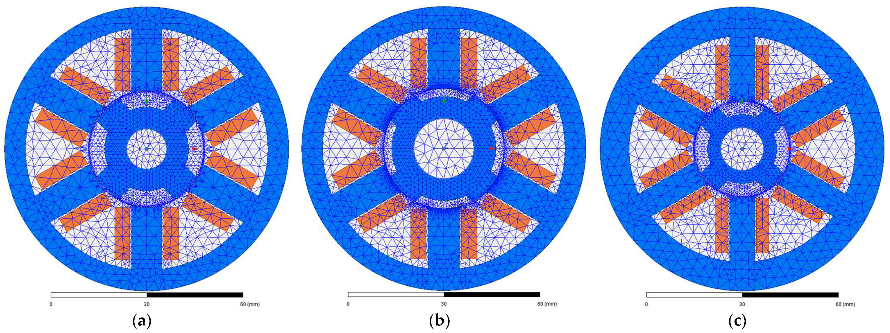
The first was magnetostatic analysis, which was used to solve the steady state of the magnetic field. The finite element model, together with the network of elements, is shown in Figure 2. This figure shows three models at different stages of motor design. Figure 2a shows the state of the design shown in [14], on which no optimization had been performed. The geometric and electromagnetic parameters of this design are compared with the final design in Section 4.6. Figure 2b shows the state of the design after several optimizations, which were described in Section 2. The geometrical and electromagnetic parameters of this design are given in Table 1 and Table 2. Finally, Figure 2c shows the design after optimization that met all the specified requirements. These models were generated using Ansys—RMxprt. The default mesh determined by Ansys—Maxwell after generating the model was used in the analyses. This mesh was sufficient in terms of accuracy.
In the magnetostatic analysis, only one phase was supplied with constant current. The aim of this analysis was to obtain static parameters of the motor, which included: phase inductance, magnetic flux, co-energy, electromagnetic torque, and phase resistance. In this analysis, the rotation of the motor at a certain speed was not considered, and only static parameters of given geometry and phase current were obtained. All these parameters except the phase resistance depended on the current and rotor position. For this reason, parameters were calculated for rotor positions from 0 to 45° and for phase currents of 5 to 400 A. The parameters obtained from Ansys—Maxwell were also verified using the program FEMM. The phase resistance was calculated using the program Ansys—RMxprt, which is used for fast analytical calculation of motors. The calculated phase resistance was verified by different analytical calculations. Using RMxprt, suitable switching angles were also found, which were chosen to achieve the maximum torque.
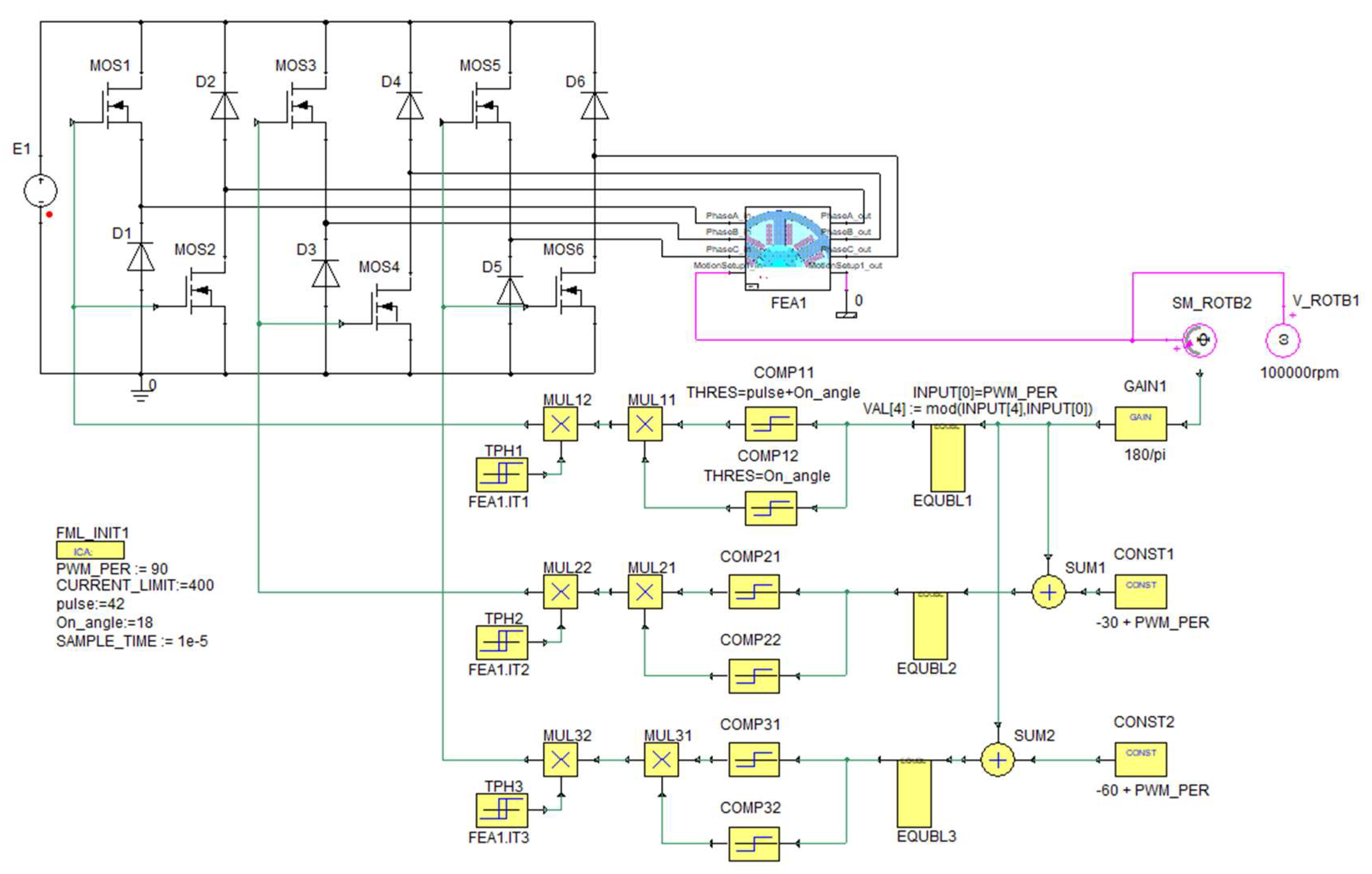
The values of these angles were needed for the transient analysis. These angles were inserted into the supply circuit required for this analysis. The supply circuit is presented in Figure 3.
This circuit was created in Ansys—Twin Builder, in which it was connected to the finite element model in Figure 2. This circuit was based on the circuit presented in [19], but several adjustments were made to the circuit in Figure 3, such as adding another phase. This model did not solve motor start-up, only the steady state at the rated speed. At the beginning of this simulation, it was assumed that the motor rotated at the rated speed, and then this speed was maintained throughout the simulation. Using this analysis, it was possible to obtain dynamic parameters of the motor at the rated speed. These parameters included waveforms: voltage, magnetic flux, supply current, phase inductance, and electromagnetic torque. Dynamic parameters were verified using a combination of FEMM with MATLAB—Simulink. Using these parameters, other parameters were calculated, such as average torque, torque ripple, and individual types of losses. The torque ripple was calculated as:
where Tmax is maximal torque and Tmin is minimal torque. Winding losses were calculated as:
where Rf75 is resistance at 75 °C and Ifrms is the RMS phase current. Iron losses were calculated with the Bertotti equation as:
where khys is the coefficient of hysteresis losses, f is the frequency, B is the peak flux density, kec is the coefficient of eddy current losses, and kexc is the coefficient of excess losses. The individual loss coefficients were calculated from the catalog data of the electromagnetic sheets using Ansys—Maxwell. Mechanical losses consisted of windage losses and bearing losses. Both types of losses were determined outside Ansys using analytical calculations presented in [14] and [16]. However, as mentioned in the previous chapter, windage losses must be calculated using a more appropriate method. The original calculation did not consider the air gap size, and losses were calculated for a certain range of loss coefficients. For these reasons, windage losses were calculated as in [20]:
where Cf is the friction coefficient, ρ is the air density, lFe is the length of the motor, rr is the rotor radius, and Ω is the angular speed. Several methods have been published for calculating the friction coefficient as a function of the Reynolds number, Re. In this case, the Wendt method was chosen. The Wendt friction coefficient can be calculated for 400 < Re < 104 as [20]:
or for 104 < Re < 105 as:
where δ is the air gap size. The Reynolds number can be calculated as [21]:
where ν is the air viscosity. However, the SRM had salient poles, and this must also be included in the calculation using the salient coefficient. This coefficient can be calculated as [21]:
where lpr is the length of the rotor pole. Windage losses were then calculated as [21]:
Additional losses were determined as 0.5% of output power. In addition to electromagnetic analysis, thermal analysis and mechanical analyses were also performed using FEM.
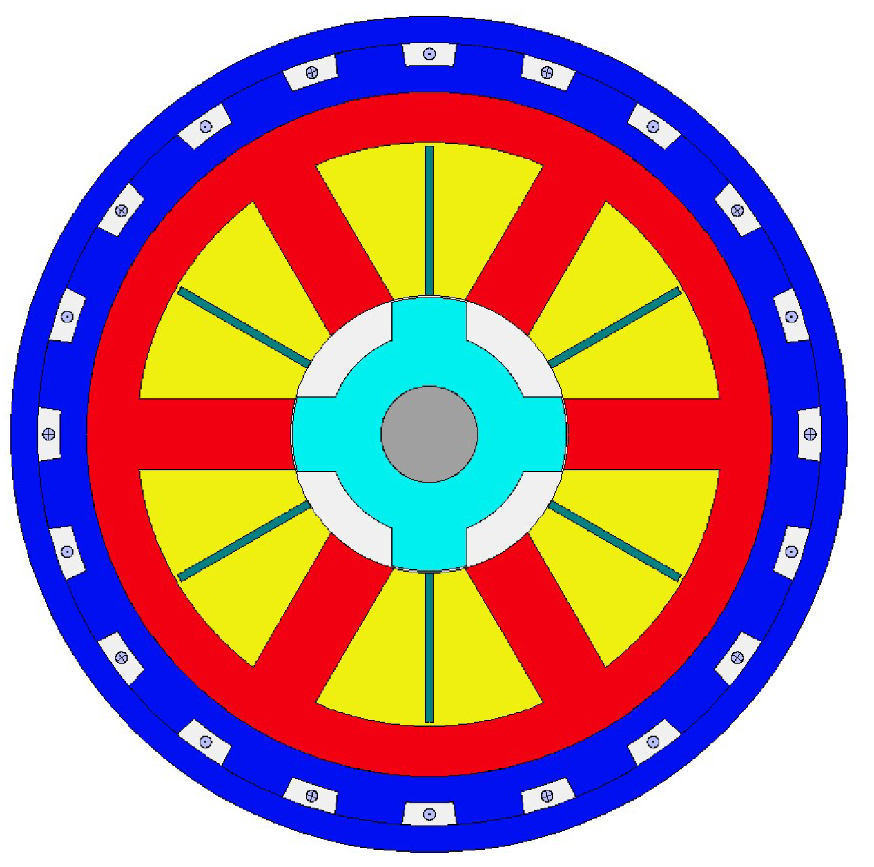
Thermal analysis was carried out by Ansys—Motor CAD, which was also used to verify the electromagnetic parameters obtained by transient analysis. In the case of the analysis in Motor CAD, it was also considered that the winding was divided into several parallel conductors, which was necessary due to the high phase current. The method of cooling is shown in Figure 4. The motor was closed, and around the stator was a frame with a diameter of 110 mm, in which axial water cooling was placed. Aluminum was chosen for the frame material and cast iron for the shaft material, which were available in the materials library. The ambient and cooling water temperature were set at 40 °C. The preliminary water flow value was set to 10 L/min. All types of losses calculated by electromagnetic analysis were entered into the program. The analysis considered the change in winding losses as a function of temperature, and the change in other types of losses as a function of rotational speed.
The mechanical analysis was performed in cooperation with the Faculties of Mechanical Engineering using Ansys—Workbench. The results of this analysis will be presented in the following sections.
4. Results
In this section, the results of electromagnetic, mechanical, and thermal analyses are presented, and at the end, the final construction of the motor is presented. In all analyses presented in this section, the following parameters had a constant value: length of the machine, number of poles, number of phases, number of turns, and supply voltage. These values are given in Section 2.
4.1. Analysis of Windage Losses
The analysis was performed for a rotor diameter of 20 to 38 mm and for an air gap size of 0.1 to 0.5 mm. The analysis was carried out for the rated speed, and in the case of the rotor with salient poles, a length of the rotor pole of 2.52 mm was considered. The results for the case of the rotor with salient poles are shown in Figure 5a. For a rotor diameter of 38 mm and an air-gap size of 0.22 mm, these losses had a value of 1922 W. Such high losses caused excessive heat that could not be reduced below the thermal limit of materials. For this reason, it was necessary to adjust the rotor to reduce these losses.
This analysis was also performed for the case of a smooth cylindrical rotor, and the results are shown in Figure 5b. Unlike the previous windage-losses analysis, this analysis assumed that the space between rotor poles was filled with material, thus changing the shape of the rotor into a cylinder. This modification did not increase the rotor diameter or reduce air gap size. In this case, there was a significant decrease in windage losses. For a rotor diameter of 38 mm and an air-gap size of 0.22 mm, these losses had a value of 806.1 W. Based on these results, it was decided to modify the rotor geometry to a smooth cylindrical rotor.
4.2. Mechanical Analysis of Various Rotor Modifications
Mechanical analysis was performed to determine a suitable method of forming a smooth cylindrical rotor. Von Mises stress and sheet deformation were monitored during the analysis. All mechanical calculations were performed for the motor design listed in Table 1.
4.2.1. Flux Bridges between Rotor Poles
In the first modification, the rotor poles were connected by bridges that were supported in the middle of the gap between the rotor poles. These bridges and supports were composed of the same material as the rotor. This rotor modification was used in the construction of the SRM for a speed of 50,000 rpm in [22]. From an electromagnetic point of view, this modification caused a decrease in torque; therefore, these bridges should be as thin as possible. However, with the thickness of bridges shown in Figure 6, this construction did not meet the mechanical aspect. At 100,000 rpm, mechanically stronger rotor material would be required for this modification.
4.2.2. Sleeve around the Rotor
A better modification of the rotor at the rated speed was to use a sleeve, as in the case of PMSMs. In contrast to the previous modification, in this modification, the sleeve was not supported in the middle of the gap between the rotor poles, but nevertheless, there was a decrease in Von Mises stress of 76 MPa. This rotor modification was used in the construction of the SRM for speed of 750,000 rpm in [23]. The thickness of the sleeve was 0.2 mm, which was the same thickness as that of the bridges in the case of the previous analysis. However, when using this modification, it was necessary to increase the air-gap size due to higher deformation, but above all to provide sufficient space for the sleeve. It was necessary to use a material such as carbon fiber for the sleeve in which there were no losses caused by eddy currents, which would cause further heating of the rotor. Figure 6 shows the results of a mechanical analysis of a rotor with a sleeve. The sleeve was glued to the rotor. The glue was placed between upper part of the rotor pole and the sleeve itself. The contact between the sleeve and the rotor was defined in Ansys Workbench as Bonded. The rotor with the sleeve was loaded with a rotational velocity of 10,472 rad/s.
Much better results could be obtained if the sleeve was slid onto the rotor. In this case, the sleeve was heated during manufacturing to increase its diameter so that it could then be slid onto the rotor. After the sleeve had cooled, its diameter was reduced, and a force was created between the sleeve and the rotor to hold the sleeve in place. Figure 7 shows the results of the mechanical analysis of a sleeve that was only slid onto the rotor (without gluing). The sleeve is shown without a rotor. The sleeve was loaded at a rotational velocity of 10,472 rad/s.
In both cases, there was a slight increase in windage losses, as the air-gap size decreased by the width of the sleeve, and the rotor diameter increased by twice the width of the sleeve.
4.2.3. Material between Poles
Finally, the possibility of filling the space between the poles with nonconductive and nonmagnetic material was analyzed. Several modifications to the rotor shape were made to fix the material. These modifications included placing pole heads on the tip of the rotor poles, a cutout in the rotor yoke, and a cutout at the points where the rotor poles protruded from the rotor yoke. Out of these three variants, the third variant was the best, but nevertheless, the maximum Von Mises stress reached up to 925 MPa. From a mechanical point of view, none of these variants was suitable. At the end, the possibility of fixing the material with glue was analyzed. The analysis showed a significant decrease in Von Mises stress to 587 MPa and minimal deformation to 0.01 mm. However, the use of a sleeve was still superior.
4.3. Preliminary Thermal Analysis
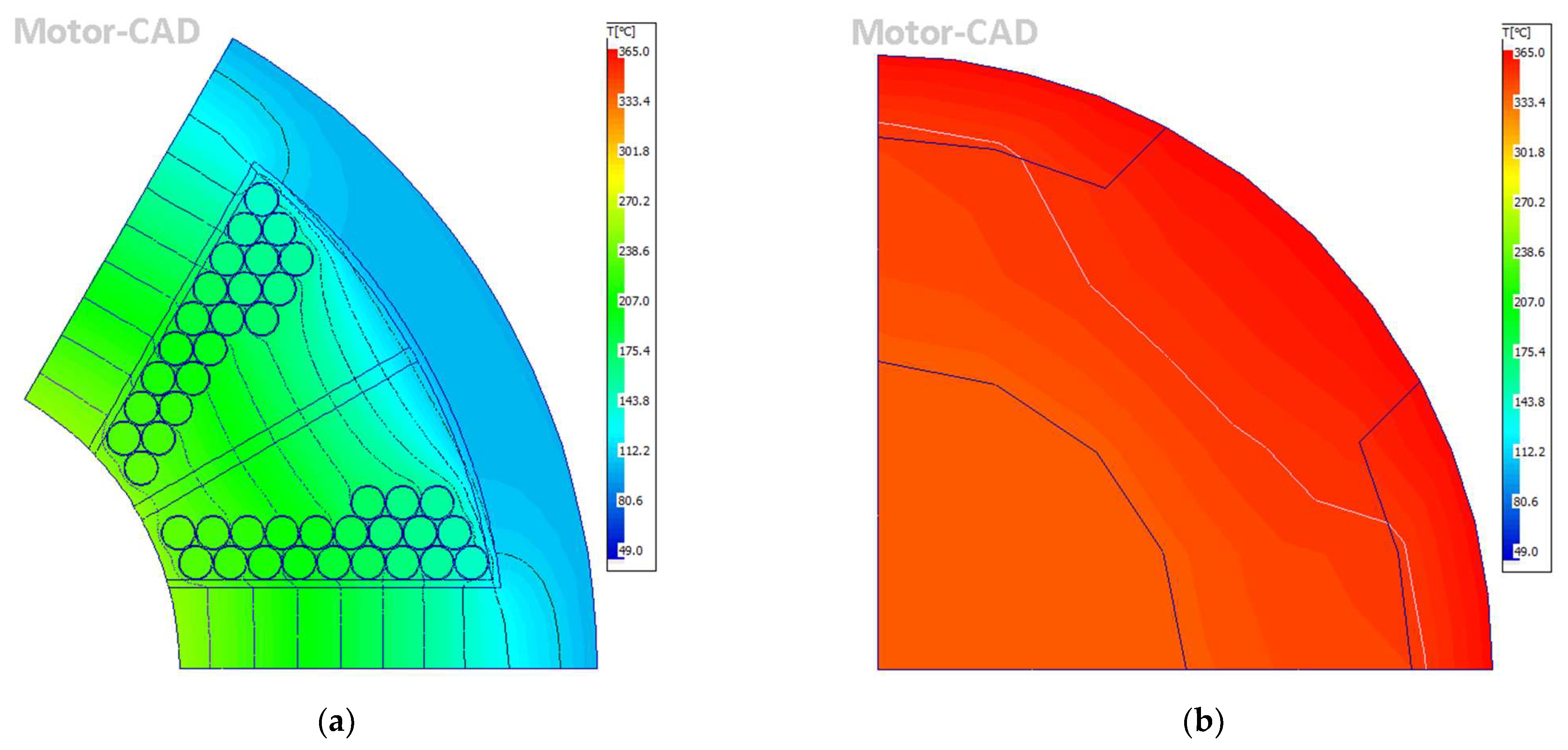
Two thermal analyses were performed. In the first analysis, the losses values obtained at the rated speed were used. These losses were constant during the simulation. In the second analysis, a duty cycle was implemented in which the motor started from zero speed to the rated speed, and then the speed was reduced until the machine stopped. In this analysis, the losses varied with speed. The aim of the analyses was to determine whether the creation of a smooth cylindrical rotor would reduce losses so that the thermal limits of the motor were not exceeded. In the simulations, the motor temperature changed over time, so only the steady state of this thermal analysis, which occurred after the temperature had stabilized, is shown in Figure 8. Bearing losses at 50% load and windage losses calculated for the smooth cylindrical rotor were included in the simulation. All thermal calculations were performed for the motor design listed in Table 1.
High heat was generated near the air gap, which affected the entire motor. This heat could not be reduced by increasing the water flow or adjusting the cooling channels. This heating was generated in the machine during continuous operation.
Based on the results shown in Figure 9, it was shown that this warm-up occurred within approximately 10 min of machine operation. Figure 9 shows the temperature change of the most important parts of the motor from the beginning of the simulation until the temperature stabilization, as shown in Figure 8. However, due to its application, this motor will not run continuously, but in a defined duty cycle. Therefore, thermal analysis respecting this cycle was performed, and the results are shown in Figure 10.
The duty cycle consisted of a shorter interval during which the motor was connected to the supply voltage, and a longer interval during which the motor was disconnected from the supply voltage. In the shorter interval, the motor started from zero and increased to the rated speed, and worked at this speed for some time. In the longer interval, the electromagnetic losses decreased almost immediately to zero, but the mechanical losses decreased gradually depending on the speed. At the end of longer interval, a complete stopping of the motor was assumed.
The implementation of the motor duty cycle improved cooling and significantly reduced the temperature. However, the rotor was still heated to 172.1 °C, which was more than the limit of the sheet. The stator and rotor sheets had a temperature limit of 150 °C. Therefore, it was necessary to reduce the rotor diameter to reach this limit. This analysis is presented in the following section.
4.4. Rotor Optimization
In this section, the rotor was optimized to achieve required output power while maintaining thermal and mechanical limits. In these analyses, all stator parameters had constant values as shown in Table 1.
4.4.1. Increase of Phase Current
In a previous work [18], by optimizing the rotor geometry for a maximum phase current of 200 A, the average torque was increased to 0.538 Nm. However, it still failed to achieve the required output power of 8 kW. Therefore, the maximum phase current increased. During this analysis, the shaft diameter and the length and width of the rotor poles were variable parameters. The rotor diameter had a constant value of 38 mm and an air gap of 0.22 mm. Increasing length and decreasing width of rotor poles led to an increase in the maximum phase current. Therefore, an analysis was performed in which the geometric dimensions of the poles were changed regardless of the maximum phase current. The goal was to achieve the required output power. By changing the length of the rotor poles, the shaft diameter was changed in this analysis. However, the required output power could not be achieved, even with very long rotor poles, which would reduce the shaft diameter to 7 mm. According to [10], such a small shaft diameter is at the limit of manufacturability. In addition, this analysis was performed with a rotor diameter of 38 mm. However, according to the results of the preliminary thermal analysis, it was necessary to reduce rotor diameter, which made the situation even worse.
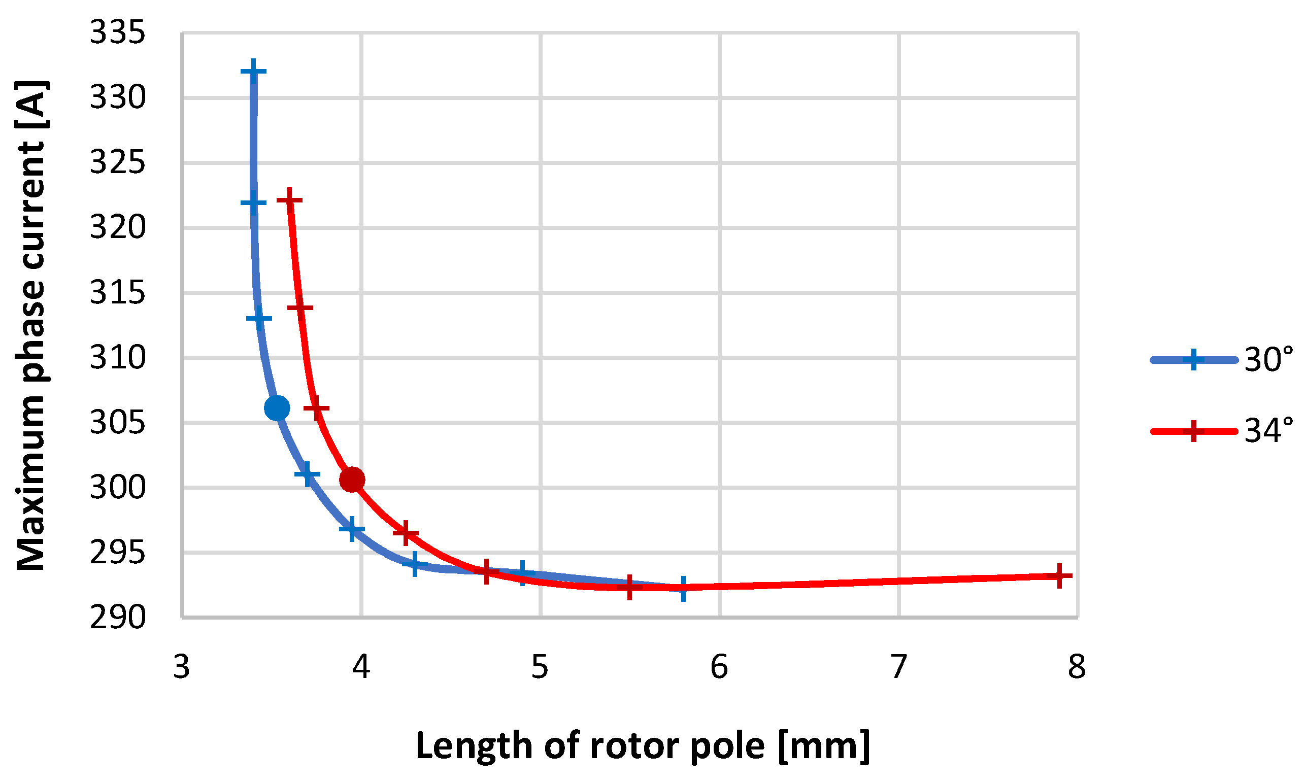
An increase in the maximum phase current can also be achieved by shifting the switching angles. Therefore, an analysis was performed in which the geometry of the rotor poles was adjusted to achieve the required output power at different values of the advance angle. The aim was to find a compromise between changing the advance angle and changing the rotor pole geometry. The SRM control used the parameters On angle (“On_angle” in Figure 3) and pulse length (“pulse” in Figure 3). An On angle equal to 0° usually represents the unaligned position of the rotor. In this position, the rotor pole was located exactly between the two stator poles. The advance angle represents the motor control parameter at which the phase of motor is switched on before unaligned position. This parameter is usually negative. However, since the supply circuit in Figure 3 had a problem operating with negative values, an On angle of 0° represented −30°. The pulse length was held constant at 42° throughout this analysis. The results of this analysis are shown in Figure 11.
The analysis was performed for an advance angle of −14 to −22°. It was not possible to achieve the required output power with a smaller advance angle. The individual points in Figure 11 represent designs for different advance angles, with the value of this angle varying from −22° to −15° from right to left. The analysis was performed for two values of the rotor pole arc. All points in Figure 11 represent possible motor designs. At lower values of the advance angle, the maximum phase current did not change significantly, but by increasing the advance angle, the rotor poles could be much shorter. By further increasing the advance angle, the maximum phase current began to increase, but was still possible to achieve a significant reduction in the length of the rotor poles. An advance angle greater than −20° had no effect on shortening the rotor poles, and only caused an excessive increase in the maximum phase current. Based on these results, an advance angle of −19° was chosen for further analysis. The results of torque ripple and losses are shown in Table 3.
As more emphasis was placed on shortening the rotor poles so that the shaft diameter could be as large as possible, the rotor pole arc was also changed to 30°. This allowed the rotor poles to be shortened even more.
4.4.2. Rotor Diameter
In this analysis, the rotor diameter, shaft diameter, and length of the rotor pole were variable parameters. The length of the rotor poles was adjusted for different rotor diameters to achieve the desired output power, as in the previous analysis, but the switching angles were constant. The air gap also had a constant value of 0.22 mm and a rotor pole arc of 30°. Electromagnetic parameters and the highest rotor heating were monitored during the analysis. The results of this analysis are shown in Table 4.
As shown in to Table 4, the required output power was achieved with all mentioned rotor diameters. The largest possible rotor diameter in terms of heating was 32 mm. However, the gaps between the poles were not covered in this analysis. This heating would therefore increase further due to poorer heat dissipation by convention. For this reason, a rotor diameter of 30 mm was chosen.
Reducing the rotor diameter reduced the shaft diameter, but it was necessary to reduce heating. Table 4 shows that reducing the rotor diameter also significantly reduced the torque ripple.
4.4.3. Air-Gap Size
By reducing rotor diameter, the thermal limit of the rotor sheets was reached, so a change in the air gap size was not necessary to reduce the heating. However, the air gap had to be enlarged to provide sufficient space for the sleeve to form the smooth cylindrical rotor. In this analysis, shaft diameter, length of the rotor pole, and air-gap size were variable parameters. The rotor pole arc had a constant value of 30°, and the rotor diameter was 30 mm. The results of this analysis are shown in Table 5.
As the air-gap size increased, the maximum phase current required to achieve the required output power was significantly increased. This also caused an increase in winding losses. In addition, longer rotor poles were required to achieve the required output power. Conversely, iron losses and windage losses were reduced, which reduced motor heating. Increasing the air-gap size also further reduced the torque ripple.
To provide sufficient space for the sleeve, which had to be at least 0.2 mm thick, and to simplify production, an air gap size of 0.5 mm was chosen. With this size of the air gap, both the rotor and the stator could be made of one piece of material, which also reduced costs. Smaller sizes required additional material for the rotor.
4.5. Stator Optimization
The entire optimization was focused on the rotor, because the possibilities of stator optimization were considerably limited to ensure sufficient space for winding. Nevertheless, an analysis was performed, but the change in geometric parameters was limited to provide sufficient space for the winding. The rotor parameters, air-gap size, and stator outer diameter were constant throughout the analysis. The rotor diameter was 30 mm, the length of rotor pole was 4.5 mm, the rotor pole arc was 30°, the shaft diameter was 13.24 mm, the air-gap size was 0.5 mm, and the stator outer diameter was 90 mm.
4.5.1. Length of the Stator Poles
Because most of the parameters were kept constant, changing this parameter also changed the thickness of the stator yoke. The analysis was performed for stator poles with lengths from 21.5 to 23.5 mm in 0.5 mm steps. The lower limit was limited by the space for winding, and the upper limit by the saturation of the stator yoke, which reached 1.1 T at this pole length. The results of this analysis are shown in Table 6.
When the length of stator poles was changed, it was possible to observe the opposite trend as the length of rotor poles was changed. The average torque increased with decreasing stator pole length. Winding losses increased with decreasing pole length, which was caused by an increase in the maximum phase current. However, this increase was not high, and could be reduced if the rotor poles were adjusted to achieve the required output power. There was a much larger difference in the case of iron losses, the decrease of which occurred mainly due to the increase in the rotor yoke thickness. The disadvantage of short poles was lower saturation of the stator yoke and higher material consumption.
4.5.2. Rounding at the Junction of Poles
Similar results to those of the previous analysis could be obtained by inserting rounding with radius rsp at the point where the stator pole protruded from the yoke. The results are shown in Table 7. This modification also reduced the length of the stator poles, but the yoke thickness did not increase along the entire circumference of the motor, but only at the point of rounding.
With this modification, it was possible to achieve an unchanged saturation in the narrower part of stator yoke; and in rounding, it was possible to cut out excess material. However, this was also possible in the case of the previous analysis by reducing the outer stator diameter. According to [19], for motors with very high speeds, it is more appropriate to use a thicker stator yoke than is electromagnetically necessary to reduce the vibration of the stator. When using a large radius of rounding, there is also deformation of the winding space.
4.5.3. Stator Pole Arc
This analysis was performed for values from 30° to 38° in 1° steps. The upper limit was again limited by the space for winding. During this analysis, the length of stator poles was constant at 22.9 mm, and the rotor yoke thickness was 6.6 mm. The results are shown in Table 8.
The analysis confirmed the theoretical assumption that a smaller torque ripple could be achieved with a larger pole stator arc. However, the average torque also decreased. It was possible to achieve the same reduction in torque ripple with a lower average torque reduction by changing the switching angles. Thus, changing the stator pole arc was not advantageous.
Based on these analyses, the stator poles were shortened to 21.5 mm. The increase in output power was reduced by changing the length of the rotor poles to 4.05 mm. The stator pole arc was left at 30°. In addition, in the area where the stator pole protruded from the yoke, a rounding with a radius of 3 mm was inserted to reduce the sharp edge and adjust the saturation that occurred at this point.
4.5.4. Number of Parallel Conductors
The last stator optimization performed was the winding optimization. The winding of the designed motor consisted of six coils, which were wound on the stator poles and were connected to each other in series. The individual coils consisted of three turns; this number had already been fixed based on the analysis presented in [16]. However, the high values of phase currents required to achieve the required output power would require the use of larger diameter conductors, which would cause an increase in losses and production problems. For these reasons, it was considered to divide the individual turns into several thinner conductors, which were connected in parallel. Thus, an analysis was performed to determine the appropriate number of these conductors.
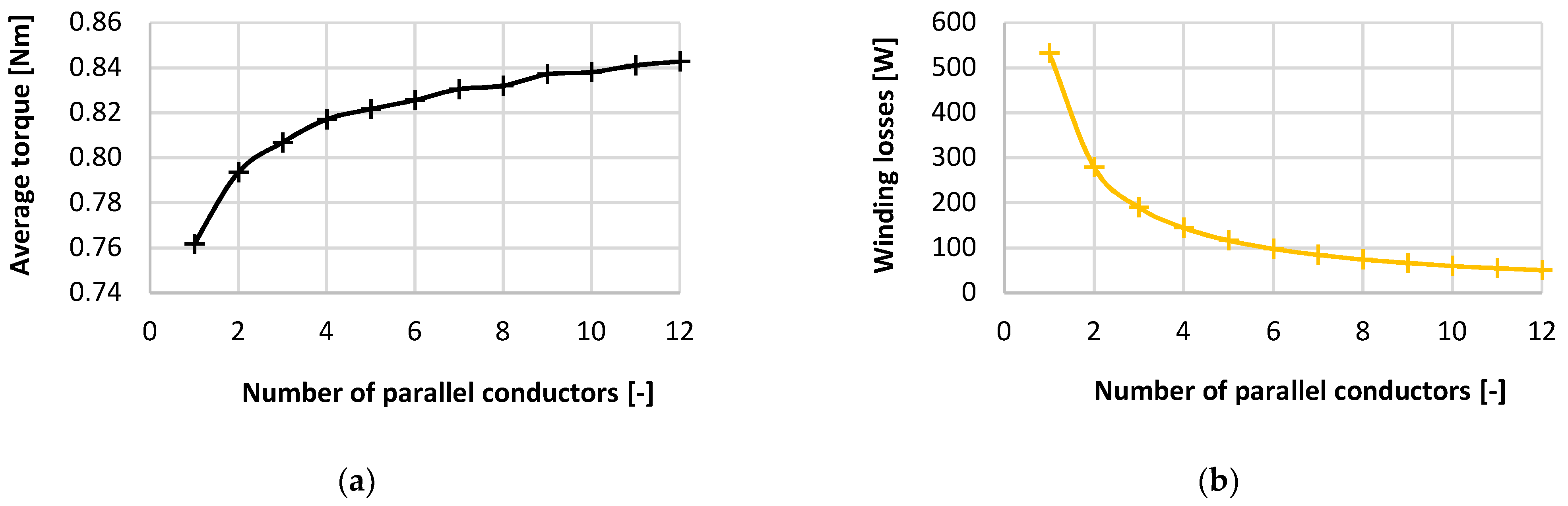
Parallel conductors with diameter of 2.12 mm were considered in the simulations. Their number was modified so that the current density did not exceed J = 10 A/mm2. However, for the given maximum phase current and conductor cross section, this led to 11 parallel conductors, which could be problematic during winding manufacturing. According to [1], the current density can be higher when using water cooling J = 23.3–31 A/mm2. For these reasons, an analysis of the parallel conductors number was performed. In this analysis, only the winding was adjusted, and all geometric dimensions were constant. The results are shown in Figure 12 and Figure 13.
As the number of parallel conductors decreased, average torque also decreased, which was caused by the decrease in the maximum phase current, which decreased with this change. Iron losses also decreased, but this decrease was small. However, this did not apply to winding losses. With a very small number of parallel conductors, these losses reached very high values.
From a thermal point of view, the thermal limit was met for each number of parallel conductors except zp = 1. At this number, the winding reached temperatures of up to 364 °C. The permissible heating temperature of the winding depends on its insulation class, with the highest insulation class having a thermal limit of 180 °C. Based on Figure 13a, it should be appropriate to use at least four parallel conductors, due to the significant increase in winding heating when using a smaller number of parallel conductors.
The current density range specified at the beginning of this section was best matched by four parallel conductors (J = 27 A/mm2) or five parallel conductors (J = 21.7 A/mm2). Since, according to Figure 12a, reducing the number of parallel conductors reduced the average torque and thus the output power, it was necessary to adjust the stator geometry to increase the output power. As shown in Table 6, it was possible to increase the output power by shortening the stator poles. This modification was realized by increasing the yoke thickness, while maintaining a constant outer stator diameter. This modification would also cause increase in phase current and thus also increase in current density. For this reason, it was more appropriate to use a higher number of parallel conductors. However, six parallel conductors (J = 18.4 A/mm2) were finally selected to ensure higher reliability in the event of a single-phase outage and a consequent increase in the maximum phase current.
4.6. Final Design
This section presents the final design of the high-speed SRM. Table 9 shows the geometrical dimensions of the final design and a comparison with the initial design. Both geometries had the same number of stator and rotor poles, outer stator diameter, and stator pole arc.
Compared to the initial design, the outer rotor diameter and rotor yoke thickness were reduced, the stator yoke thickness was increased, the stator and rotor poles were shortened, and the same pole arc was used for both parts of the motor. In addition, the stator and rotor material was changed to 10JNEX900, the control method was changed to single-pulse operation, and the number of parallel conductors was changed to six.
4.6.1. Electromagnetic Parameters
Dynamic parameters were calculated for this geometry, and are shown in Figure 14.
Using these parameters, other parameters such as average torque and losses were calculated. These parameters are listed and compared with the initial design in Table 10.
The flux density distribution for position of the highest yoke saturation is shown in Figure 15. White areas in the figures indicate that the scale range had been exceeded.
The thickness of the rotor yoke was adjusted so that the flux density did not exceed 1.1 T. This value represented the saturation point of the material, which should not be exceeded to reduce iron losses. The flux density in the stator yoke was much lower because a thicker yoke was used than was necessary from an electromagnetic point of view. However, this thicker yoke was advantageous in terms of reducing vibration. At the edge of stator yoke, there were areas where the material was very weakly saturated. These places could be cut out and used to better secure the stator to the frame.
4.6.2. Air-Flow Analysis
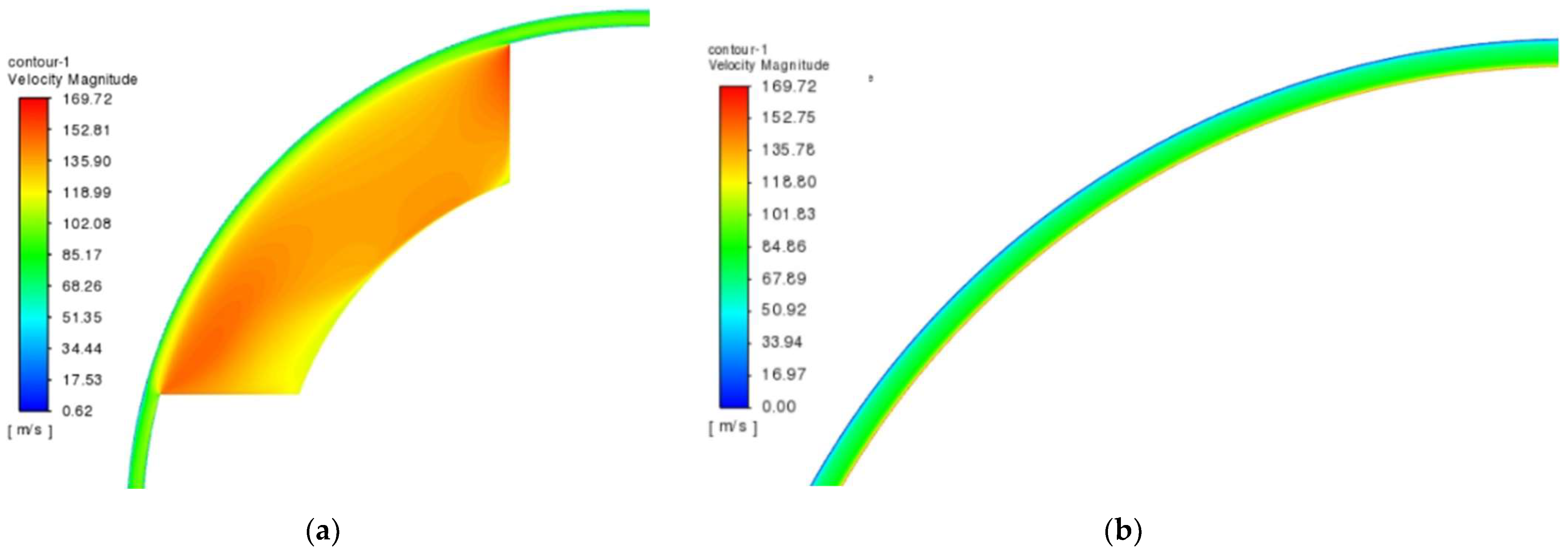
This analysis was performed in the case of the salient poles and in the case of the cylindrical rotor in the program Fluent 2D. In Figure 16, the velocity field for the rated speed is represented.
In addition, the windage losses were calculated based on the force acting against the movement of the rotor. In the case of the rotor with salient poles, these losses reached a value of 1111.8 W, which was a difference of 4.2% compared to the analytical calculation; and 432 W in the case of the smooth cylindrical rotor, which was a difference of 41.5%. These values corresponded to the rated speed. A comparison of windage losses for different speeds is shown in Figure 17.
4.6.3. Thermal Analysis
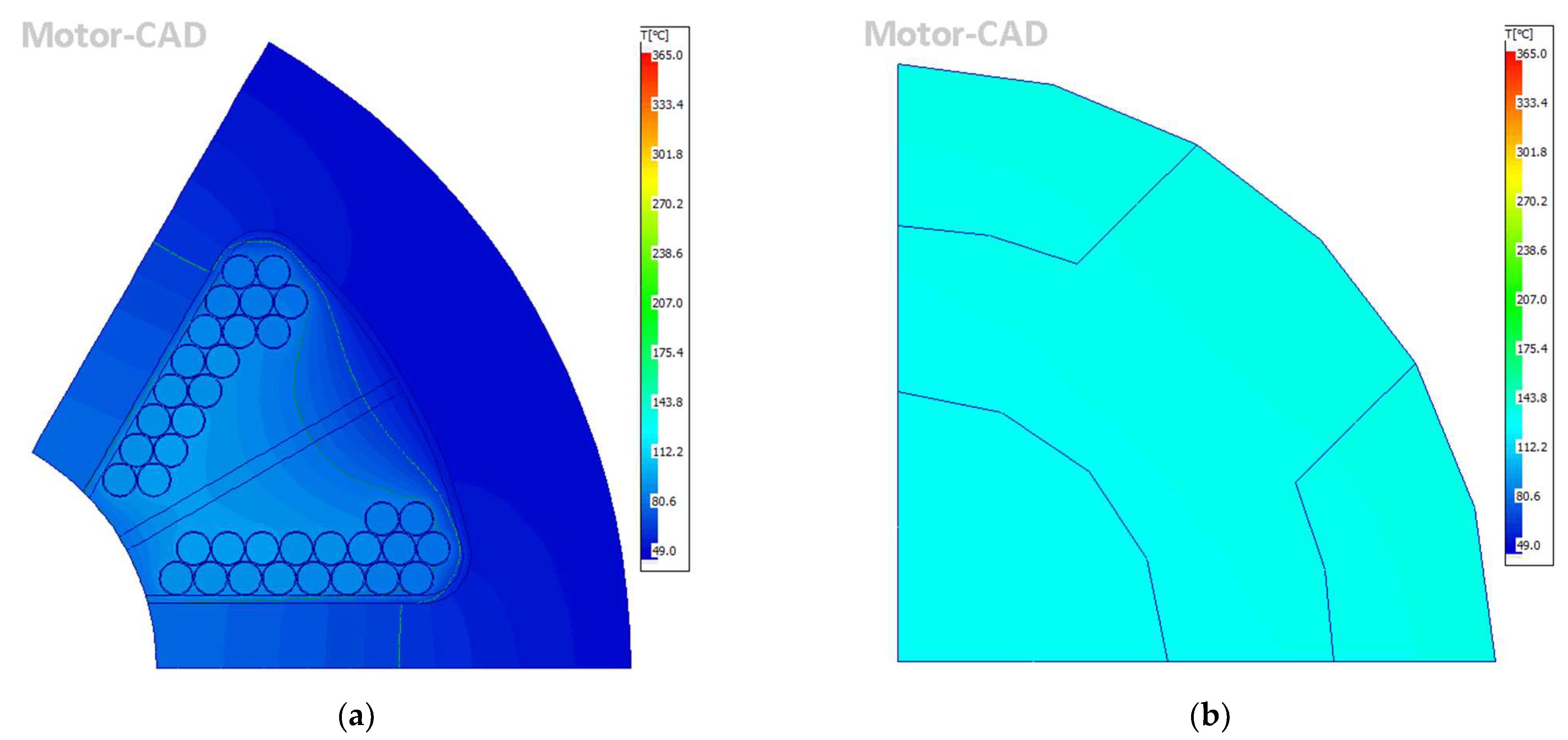
Finally, Figure 18 shows the thermal analysis of the final design of the SRM. The analysis confirmed that all thermal limits were met.
5. Discussion
In the previous work, the initial design of a high-speed SRM was presented. However, this design did not achieve the required output power, and therefore optimization was required. Several analyses were performed, but it was not possible to determine the rotor diameter and air-gap size using electromagnetic parameters alone. Therefore, the analysis of windage losses, mechanical analysis, and preliminary thermal analysis were performed in this paper. Based on the analysis of windage losses, it was concluded that a smooth cylindrical rotor was needed to reduce these losses. Mechanical analysis has shown that the most suitable method for creating this rotor is to use a sleeve around the rotor. Preliminary thermal analysis has shown that the rotor diameter must be reduced to 30 mm to meet the thermal limits. To use a sleeve, it was necessary to increase the air-gap size to 0.5 mm.
In previous work, the highest possible average torque was achieved at a phase current of 200 A. The rotor was optimized from a thermal point of view, but the required output power still was not achieved. Thus, to achieve a higher average torque, it was necessary to increase the phase current. First, the increase in phase current was realized by increasing the length of the rotor poles. However, the required output power could not be achieved, even with very long rotor poles. The phase current could also be influenced by changing the advance angle. Therefore, optimization was performed to find a compromise between the phase current and the length of the rotor poles. Using this analysis, several possible designs were found that achieved the required output power of 8 kW, while the design with the shortest rotor poles was chosen so that a shaft with a larger diameter could be used.
The entire optimization was focused on the rotor, because modification of the rotor was limited due to the provision of sufficient space for winding. An analysis of the stator parameters was also performed for completeness. The analysis showed that it was possible to increase the average torque by shortening the length of the stator pole. The disadvantages of this change were the reduction of space for windings and a lower saturation of the stator yoke, because this shortening causes an increase in the thickness of the stator yoke. An increase in the average torque could also be achieved by inserting a rounding at the point where the stator pole protruded from the stator yoke. By increasing the pole width, it was possible to reduce the torque ripple, but the decrease in average torque was too high, so this change was not advantageous. The number of parallel conductors was reduced from 11 to 6 to facilitate winding manufacturing. This change caused a decrease in the average torque and an increase in the winding losses, which caused a decrease in output power. This decrease was replaced by shortening the stator poles.
Finally, the final geometry of motor was presented together with dynamic parameters, flux density distribution, and the results of the thermal analysis. The given geometry met the set requirements and limits. However, it was still possible to optimize the stator to better distribute the flux density or to reduce the maximum phase current. It was possible to reduce the stator’s outer diameter or to cut out areas with low saturation to improve the flux density distribution. By further shortening the stator poles and subsequently reducing the advance angle, it was possible to achieve a reduction in the phase current. In addition, cooling could be optimized by reducing the water flow or the number of cooling channels. However, the simulation results for the motor prototype will be experimentally verified before further optimization.
6. Conclusions
The initial design of the high-speed SRM achieved high total losses and low efficiency, and did not achieve the required output power. Therefore, several analyses were performed to optimize this design. From an electromagnetic point of view, the geometry was adjusted to achieve the required output power and a good flux density distribution; and from a mechanical point of view, to use the largest possible shaft diameter.
Compared to the initial design, in addition to achieving the required output power, the total losses were also reduced, which led to an increase in efficiency of 41.5%, and thus to a reduction in energy consumption. This improvement was achieved by reducing windage losses by modifying the rotor design, since a smooth cylindrical rotor was not considered in the initial design. If a smooth cylindrical rotor was considered in the case of the initial design, this improvement would be lower. Nevertheless, efficiency was improved by 18.5%. This improvement was achieved by further reducing windage losses by reducing the rotor diameter, but also by reducing iron losses by selecting more suitable material.
Another improvement over the initial design was a 71.7% reduction in torque ripple. However, to achieve the required output power, it was necessary to increase the maximum phase current by 143.7 A, which led to more than an increase in winding losses of more than four times.
The main result of this paper was the optimized electromagnetic design high-speed SRM, which achieved an output power of 8 kW at a rotational speed of 100,000 rpm. In addition, windage losses were calculated using a procedure suitable for high-speed motors; the method for reducing them was determined based on mechanical analyses; and finally, thermal analysis was performed for the design. In all the analyses, modern and scientific methods and programs were used, and were based on the finite element method or analytical methods.
Author Contributions
Conceptualization, methodology, S.K. and P.R.; validation, P.R.; formal analysis, S.K., R.B., M.S., and R.L.; software, investigation, resources, data curation, writing—original draft preparation, visualization, S.K.; first review, P.R.; funding acquisition, supervision, P.R. All authors have read and agreed to the published version of the manuscript.
Funding
This work was supported by the Slovak Scientific Grant Agency VEGA (No. 1/0615/19). This publication was realized with the support of the Operational Program Integrated Infrastructure 2014–2020 of the project: Innovative Solutions for Propulsion, Power and Safety Components of Transport Vehicles, code ITMS 313011V334, co-financed by the European Regional Development Fund.
Institutional Review Board Statement
Not applicable.
Informed Consent Statement
Not applicable.
Data Availability Statement
Data sharing is not applicable.
Conflicts of Interest
The authors declare no conflict of interest.
References
- Gerada, D.; Mebarki, A.; Brown, N.L.; Gerada, C.; Cavagnino, A.; Boglietti, A. high-speed electrical machines: Technologies, trends, and developments. IEEE Trans. Ind. Electron. 2014, 61, 2946–2959. [Google Scholar] [CrossRef]
- Rahman, M.A.; Chiba, A.; Fukao, T. Super high speed electrical machines-summary. In Proceedings of the IEEE Power Engineering Society General Meeting, Denver, CO, USA, 6–10 June 2004; pp. 1–4. [Google Scholar] [CrossRef]
- Hieu, P.T.; Lee, D.H.; Ahn, J.W. Design of a high speed 4/2 switched reluctance motor for blender application. In Proceedings of the IEEE Transportation Electrification Conference and Expo, Asia-Pacific (ITEC Asia-Pacific), Harbin, China, 7–10 August 2017; pp. 1–5. [Google Scholar]
- McGuiness, D.T.; Gulbahce, M.O.; Kocabas, D.A. A performance comparison of different rotor types for high-speed induction motors. In Proceedings of the ELECO 2015 IEEE: 9th International Conference on Electrical and Electronics Engineering, Bursa, Turkey, 26–28 November 2015; pp. 584–589. [Google Scholar]
- Uzhegov, N.; Barta, J.; Kurfurst, J.; Ondrusek, C.; Pyrhonen, J. Comparison of High-Speed Electrical Motors for a Turbo Cir-culator Application. IEEE Trans. Ind. Appl. 2017, 53, 4308–4317. [Google Scholar] [CrossRef]
- Lim, M.-S.; Kim, J.-M.; Hwang, Y.S.; Hong, J.-P. Design of an ultra-high-speed permanent-magnet motor for an electric turbocharger considering speed response characteristics. IEEE/ASME Trans. Mechatron. 2017, 22, 774–784. [Google Scholar] [CrossRef]
- Bianchi, N.; Bolognani, S.; Luise, F. Potentials and limits of high speed PM motors. In Proceedings of the 38th IAS Annual Meeting on Conference Record of the Industry Applications Conference, Salt Lake City, Salt Lake City, UT, USA, 12–16 October 2003; pp. 1570–1578. [Google Scholar] [CrossRef]
- Dong, J.; Huang, Y.; Jin, L.; Lin, H. Comparative study of surface-mounted and interior permanent-magnet motors for high-speed applications. IEEE Trans. Appl. Supercond. 2016, 26, 1–4. [Google Scholar] [CrossRef]
- Vag, L.; Laksar, J. Overview of technology, problems and comparison of high speed synchronous reluctance machines. In Proceedings of the 12th International Conference on ELEKTRO, Mikulov, Czech Republic, 1 March–23 May 2018; pp. 1–4. [Google Scholar]
- Chayopitak, N.; Pupadubsin, R.; Karukanan, S.; Champa, P.; Somsiri, P.; Thinphowong, Y. Design of a 1 5 kW high speed switched reluctance motor for electric supercharger with optimal performance assessment. In Proceedings of the 15th International Conference on Electrical Machines and Systems (ICEMS), Sapporo, Japan, 21–24 October 2012; pp. 1–5. [Google Scholar]
- Fairall, E.W.; Bilgin, B.; Emadi, A. State-of-the-art high-speed switched reluctance machines. In Proceedings of the 2015 IEEE International Electric Machines & Drives Conference (IEMDC), Coeur d’Alene, ID, USA, 10–13 May 2015; pp. 1621–1627. [Google Scholar]
- Besharati, M.; Atkinson, G.; Widmer, J.; Pickert, V.; Pullen, K. Investigation of the mechanical constraints on the design of a super-high-speed switched reluctance motor for automotive traction. In Proceedings of the 7th IET International Conference on Power Electronics, Machines and Drives (PEMD 2014), Manchester, UK, 8–10 April 2014; Volume 1. [Google Scholar]
- Kozuka, S.; Tanabe, N.; Asama, J.; Chiba, A. Basic characteristics of 150,000 r/min switched reluctance motor drive. In Proceedings of the 2008 IEEE Power and Energy Society General Meeting-Conversion and Delivery of Electrical Energy in the 21st Century, Pittsburgh, PA, USA, 20–24 July 2008; pp. 1–4. [Google Scholar]
- Kocan, S.; Rafajdus, P.; Makys, P.; Bastovansky, R. Design of high speed switched reluctance motor. In Proceedings of the 2018 IEEE International Conference and Exposition on Electrical And Power Engineering (EPE), Iasi, Romania, 18–19 October 2018; pp. 421–426. [Google Scholar]
- Kocan, S.; Rafajdus, P. Dynamic model of high speed switched reluctance motor for automotive applications. Transp. Res. Procedia 2019, 40, 302–309. [Google Scholar] [CrossRef]
- Kocan, S.; Rafajdus, P.; Makys, P.; Bastovansky, R. Number of turns influence on the parameters of high speed switched reluctance motor. In Proceedings of the 2019 IEEE International Aegean Conference on Electrical Machines and Power Electronics (ACEMP) & 2019 International Conference on Optimization of Electrical and Electronic Equipment (OPTIM), Istanbul, Turkey, 2–4 September 2019; pp. 240–245. [Google Scholar]
- Kocan, S.; Rafajdus, P.; Sumega, M. Effect of air gap size on parameters of high speed switched reluctance motor. In Proceedings of the 13th International Conference Elektro, Taormina, Italy, 25–28 May 2021; pp. 1–5. [Google Scholar]
- Kocan, S.; Rafajdus, P.; Kovacik, M. Investigation of rotor parameters of high speed switched reluctance motor for auto-motive application. Transp. Res. Procedia 2021, 55, 1003–1010, in press. [Google Scholar] [CrossRef]
- Gong, C.; Habetler, T. Electromagnetic design of an ultra-high speed switched reluctance machine over 1 million rpm. In Proceedings of the 2017 IEEE Energy Conversion Congress and Exposition (ECCE), Cincinnati, OH, USA, 1–5 October 2017; pp. 2368–2373. [Google Scholar] [CrossRef]
- Sadr, S.; Abdelli, A.; Ben-NachouaneIntuitive, A.; Friedrich, G.; Vivier, S. Comprehension and estimation of windage losses in rotor slotted air gaps of electrical machines using CFD-LES methods. In Proceedings of the 2019 IEEE Energy Conversion Congress and Exposition (ECCE), Baltimore, MD, USA, 29 September–3 October 2019; pp. 6078–6083. [Google Scholar] [CrossRef]
- Zhang, J.; Wang, H.; Chen, L.; Tan, C.; Wang, Y. Salient pole rotor with partially covered shrouds for the windage loss re-duction of bearingless switched reluctance motors. In Proceedings of the 13th IEEE Conference on Industrial Electronics and Applications (ICIEA), Wuhan, China, 31 May–2 June 2018; pp. 868–873. [Google Scholar]
- Dang, J.; Haghbin, S.; Du, Y.; Bednar, C.; Liles, H.; Restrepo, J.; Mayor, J.R.; Harley, R.; Habetler, T. Electromagnetic design considerations for a 50,000 rpm 1 kW Switched Reluctance Machine using a flux bridge. In Proceedings of the 2013 IEEE International Electric Machines & Drives Conference, Chicago, IL, USA, 12–15 May 2013; pp. 325–331. [Google Scholar]
- Kunz, J.; Cheng, S.; Duan, Y.; Mayor, J.R.; Harley, R.; Habetler, T. Design of a 750,000 rpm Switched Reluctance Motor for Micro Machining. In Proceedings of the IEEE Energy Conversion Congress and Exposition (ECCE), Atlanta, GA, USA, 12–16 September 2010; pp. 3986–3992. [Google Scholar]
Figure 1.
Definitions of the individual geometric dimensions. The displayed geometry is for illustration only; i.e., the values of individual dimensions do not correspond to the values in the table.
Figure 1.
Definitions of the individual geometric dimensions. The displayed geometry is for illustration only; i.e., the values of individual dimensions do not correspond to the values in the table.

Figure 2.
Finite element model from Ansys—Maxwell 2D: (a) initial design—before optimization; (b) basic design—after several optimizations; (c) final design—after optimization, and without a sleeve. The individual colors represent the materials used: blue—sheet material; orange—winding material; white—air.

Figure 3.
Supply circuit from Ansys—Twin Builder. Description of individual symbols: E—voltage source; D—diode; MOS—MOSFET transistor; FEA—FEM model of motor; SM_ROTB—rotational angle meter; V_ROTB—rotational angular velocity source; GAIN—proportional gain; EQUBL—equation block; CONST—constant value; COMP—comparator; MUL—multiplier; TPH—signal processing block—two-point element with hysteresis.

Figure 4.
The method of cooling. The individual colors represent parts of the motor: dark blue—frame with cooling channels; red—stator sheets; yellow—stator winding; green—coil divider, insulation between coils; white—empty space, filled with water in the case of cooling channels or air in the case of the air gap between the rotor and stator; light blue—rotor sheets; grey—shaft.

Figure 5.
Results of the windage losses analysis: (a) salient poles; (b) smooth cylindrical rotor.

Figure 6.
Mechanical analysis of the sleeve glued to the rotor: (a) Von Mises stress; (b) total deformation.
Figure 6.
Mechanical analysis of the sleeve glued to the rotor: (a) Von Mises stress; (b) total deformation.

Figure 7.
Mechanical analysis of the sleeve slid onto the rotor: (a) Von Mises stress; (b) total deformation.
Figure 7.
Mechanical analysis of the sleeve slid onto the rotor: (a) Von Mises stress; (b) total deformation.

Figure 8.
The distribution of temperature at steady state: (a) stator; (b) rotor.

Figure 9.
The temperatures of individual motor parts as a function of time: blue curve—rotor heating; red curve—stator heating; yellow—windage heating.
Figure 9.
The temperatures of individual motor parts as a function of time: blue curve—rotor heating; red curve—stator heating; yellow—windage heating.

Figure 10.
The distribution of temperature at steady state with duty cycle: (a) stator; (b) rotor.

Figure 11.
Possible designs with an output power of 8 kW. Each discrete point indicates a possible motor design, and the symbol ● indicates the finally selected motor design.
Figure 11.
Possible designs with an output power of 8 kW. Each discrete point indicates a possible motor design, and the symbol ● indicates the finally selected motor design.

Figure 12.
Results of the electromagnetic analysis for different numbers of parallel conductors: (a) average torque; (b) winding losses.
Figure 12.
Results of the electromagnetic analysis for different numbers of parallel conductors: (a) average torque; (b) winding losses.

Figure 13.
Results of the thermal analysis for different numbers of parallel conductors: (a) temperature of winding; (b) temperature of rotor surface.
Figure 13.
Results of the thermal analysis for different numbers of parallel conductors: (a) temperature of winding; (b) temperature of rotor surface.

Figure 14.
Dynamic parameters of the high-speed SRM at the rated speed: (a) phase voltage; (b) phase current; (c) phase inductance; (d) torque of all three phases.
Figure 14.
Dynamic parameters of the high-speed SRM at the rated speed: (a) phase voltage; (b) phase current; (c) phase inductance; (d) torque of all three phases.

Figure 15.
Flux density distribution for rotor position of the highest yoke saturation that occurred in the rotor.
Figure 15.
Flux density distribution for rotor position of the highest yoke saturation that occurred in the rotor.

Figure 16.
Velocity field contours inside the air gap at 100,000 rpm: (a) salient poles; (b) smooth cylindrical rotor.
Figure 16.
Velocity field contours inside the air gap at 100,000 rpm: (a) salient poles; (b) smooth cylindrical rotor.

Figure 17.
Comparison of windage losses for different speeds: (a) salient poles, (b) smooth cylindrical rotor.
Figure 17.
Comparison of windage losses for different speeds: (a) salient poles, (b) smooth cylindrical rotor.

Figure 18.
The distribution of temperature at steady state of the final design: (a) stator; (b) rotor.
Figure 18.
The distribution of temperature at steady state of the final design: (a) stator; (b) rotor.


Table 1.
Summary of the mechanical parameters of the basic high-speed SRM design.
| Parameter | Symbol | Value |
|---|---|---|
| Number of stator poles | Ns | 6 |
| Number of rotor poles | Nr | 4 |
| Outer stator diameter | ds | 90 mm |
| Outer rotor diameter | dr | 38 mm |
| Length of stator poles | lps | 20.18 mm |
| Length of rotor poles | lpr | 2.52 mm |
| Stator pole arc | βs | 30° |
| Rotor pole arc | βr | 34° |
| Yoke thickness of stator | hys | 6.6 mm |
| Yoke thickness of rotor | hyr | 6.95 mm |
Table 2.
Summary of the electrical parameters of the basic high-speed SRM design.
| Parameter | Symbol | Value |
|---|---|---|
| Number of phases | m | 3 |
| Number of turns | N | 3 |
| Maximum phase current | Imax | 200 A |
| Supply voltage | VDC | 48 V |
| Phase resistance at 75 °C | R | 0.85 mΩ |
| Average torque | Tav | 0.538 Nm |
| Torque ripple | ΔT | 235.57% |
| Winding losses | ΔPj | 21,47 W |
| Iron losses | ΔPFe | 177.23 W |
| Windage losses | ΔPw | 2.17 kW |
| Bearing losses (50% Co) | ΔPb | 196.3 W |
| Addition losses | ΔPad | 15.3 W |
| Output power | P2 | 3.05 kW |
| Efficiency | η | 54.2% |
Table 3.
Torque ripple and losses for different advance angles for a rotor pole arc of 34°.
| Angle (°) | 8 (−22) | 9 (−21) | 10 (−20) | 11 (−19) | 12 (−18) | 13 (−17) | 14 (−16) | 15 (−15) |
|---|---|---|---|---|---|---|---|---|
| ΔT (%) | 205 | 198 | 193 | 189 | 184 | 181 | 179 | 175 |
| ΔPj (W) | 44.7 | 42.3 | 40.1 | 38.3 | 36.8 | 35.6 | 34.7 | 34.1 |
| ΔPFe (W) | 299 | 304 | 309 | 313 | 316 | 320 | 328 | 327 |
Table 4.
Results of the rotor-diameter analysis.
| dr (mm) | dh (mm) | Imax (A) | Tav (Nm) | ΔT (%) | ΔPj (W) | ΔPFe (W) | ΔPw (W) | P2 (kW) | ϑmax 1 (°C) |
|---|---|---|---|---|---|---|---|---|---|
| 38 | 19.5 | 302 | 0.897 | 184 | 37.4 | 295.8 | 806 | 8.04 | 175 |
| 36 | 18.3 | 295.3 | 0.879 | 178 | 37.5 | 295.4 | 676 | 8 | 164 |
| 34 | 17 | 294.7 | 0.871 | 167 | 37.9 | 296 | 562 | 8.02 | 156.7 |
| 32 | 15.7 | 294.4 | 0.861 | 160 | 38.6 | 294.8 | 461 | 8.02 | 147.1 |
| 30 | 14.2 | 295 | 0.851 | 151 | 39.8 | 295.3 | 374 | 8.02 | 142.7 |
| 28 | 12.4 | 298.1 | 0.847 | 143 | 42.3 | 293 | 299 | 8.04 | 134.6 |
| 26 | 10.4 | 303.4 | 0.837 | 134 | 45.8 | 283.4 | 235 | 8 | 130.4 |
1 Maximum rotor temperature.
Table 5.
Results of the air-gap-size analysis.
| δ (mm) | lpr (mm) | Imax (A) | Tav (Nm) | ΔT (%) | ΔPj (W) | ΔPFe (W) | ΔPw (W) | P2 (kW) |
|---|---|---|---|---|---|---|---|---|
| 0.22 | 3.1 | 295 | 0.851 | 151 | 39.8 | 295.3 | 374 | 8.02 |
| 0.3 | 3.4 | 315.2 | 0.847 | 145 | 43 | 287.6 | 346.3 | 8 |
| 0.4 | 3.9 | 331.7 | 0.847 | 133 | 48.9 | 281 | 322.6 | 8.02 |
| 0.5 | 4.5 | 346.3 | 0.844 | 122 | 54.9 | 271.1 | 305.3 | 8.04 |
Table 6.
Results of the analysis of the length of the stator poles.
| lps (mm) | hs (mm) | Imax (A) | Tav (Nm) | ΔT (%) | ΔPj (W) | ΔPFe (W) | ΔPmech 1 (W) | P2 (kW) |
|---|---|---|---|---|---|---|---|---|
| 23.5 | 6 | 344.1 | 0.834 | 123 | 54.4 | 290.3 | 305.3 + 196.3 2 | 7.89 |
| 22.9 | 6.6 | 346.3 | 0.844 | 122 | 54.9 | 271.1 | 8.01 | |
| 22.5 | 7 | 348.3 | 0.852 | 123 | 55.4 | 250.8 | 8.12 | |
| 22 | 7.5 | 350.6 | 0.858 | 122 | 55.7 | 229.8 | 8.2 | |
| 21.5 | 8 | 351.3 | 0.863 | 123 | 56 | 213.6 | 8.27 |
1 Windage and bearing losses. 2 These values are the same for all rows.
Table 7.
Results of the analysis of the rounding at the junction of poles.
| rsp (mm) | 1 | 2 | 3 | 4 | 5 | 6 | 7 | 8 |
|---|---|---|---|---|---|---|---|---|
| Imax (A) | 346.3 | 346.6 | 346.9 | 347.7 | 348.1 | 350.1 | 350.4 | 351.1 |
| Tav (Nm) | 0.844 | 0.845 | 0.847 | 0.85 | 0.853 | 0.858 | 0.862 | 0.865 |
| ΔPj (W) | 54.9 | 55 | 55.2 | 55.5 | 55.7 | 56.1 | 56.6 | 57 |
| ΔPFe (W) | 266.5 | 262.5 | 257.4 | 251.1 | 243.5 | 235.3 | 224.9 | 214 |
| P2 (kW) | 8.02 | 8.03 | 8.06 | 8.1 | 8.13 | 8.19 | 8.25 | 8.29 |
Table 8.
Results of the analysis of the stator pole arc.
| βs (°) | Imax (A) | Tav (Nm) | ΔT (%) | ΔPj (W) | ΔPFe (W) | ΔPmech (W) | P2 (kW) |
|---|---|---|---|---|---|---|---|
| 30 | 346.3 | 0.844 | 122.3 | 54.9 | 271.1 | 305.3 + 196.3 1 | 8.01 |
| 31 | 336.9 | 0.821 | 120.9 | 51.8 | 269.5 | 7.78 | |
| 32 | 326.6 | 0.797 | 119.3 | 48.9 | 269.4 | 7.53 | |
| 33 | 316.8 | 0.773 | 118.6 | 46.2 | 269 | 7.28 | |
| 34 | 308.5 | 0.751 | 118.8 | 43.8 | 267.4 | 7.05 | |
| 35 | 298.2 | 0.724 | 117.1 | 41.3 | 266 | 6.77 | |
| 36 | 289.3 | 0.698 | 116.3 | 39 | 264.7 | 6.51 | |
| 37 | 280.1 | 0.674 | 114.9 | 36.9 | 263.6 | 6.26 | |
| 38 | 271.1 | 0.648 | 113.4 | 34.7 | 260.4 | 6 |
1 These values are the same for all rows.
Table 9.
Comparison of the geometric parameters.
| Parameter | Initial Design | Final Design |
|---|---|---|
| Outer stator diameter | 90 mm | 90 mm |
| Outer rotor diameter | 36 mm | 30 mm |
| Length of stator poles | 20.18 mm | 20.32 mm |
| Length of rotor poles | 4.72 mm | 4.05 mm |
| Stator pole arc | 30° | 30° |
| Rotor pole arc | 32° | 30° |
| Yoke thickness of stator | 6.6 mm | 9.18 mm |
| Yoke thickness of rotor | 6.95 mm | 4.18 mm |
| Air-gap size | 0.22 mm | 0.5 mm |
| Shaft diameter | 12.68 mm | 13.54 mm |
Table 10.
Comparison of the electromagnetic parameters.
| Parameter | Initial Design | Final Design |
|---|---|---|
| Supply voltage | 48 V | 48 V |
| Maximal phase current | 203.4 A | 347.1 A |
| Sampling frequency | - | 100 kHz |
| Average torque | 0.4846 Nm | 0.844 Nm |
| Torque ripple | 194.4% | 122.7% |
| Winding losses | 23.66 W | 99.89 W |
| Iron losses | 510.89 W | 184.21 W |
| Windage losses | 1840 W | 305.3 W |
| Bearing losses | 196.3 W | 196.3 W |
| Additional losses | 12.5 W | 40 W |
| Output power | 2.49 kW | 8.01 kW |
| Efficiency | 49.13% | - |
| Efficiency (cylindrical rotor) | 72.08% | 90.63% |
Publisher’s Note: MDPI stays neutral with regard to jurisdictional claims in published maps and institutional affiliations. |
© 2021 by the authors. Licensee MDPI, Basel, Switzerland. This article is an open access article distributed under the terms and conditions of the Creative Commons Attribution (CC BY) license (https://creativecommons.org/licenses/by/4.0/).
Share and Cite
MDPI and ACS Style
Kocan, S.; Rafajdus, P.; Bastovansky, R.; Lenhard, R.; Stano, M. Design and Optimization of a High-Speed Switched Reluctance Motor. Energies 2021, 14, 6733. https://doi.org/10.3390/en14206733
AMA Style
Kocan S, Rafajdus P, Bastovansky R, Lenhard R, Stano M. Design and Optimization of a High-Speed Switched Reluctance Motor. Energies. 2021; 14(20):6733. https://doi.org/10.3390/en14206733
Chicago/Turabian StyleKocan, Stefan, Pavol Rafajdus, Ronald Bastovansky, Richard Lenhard, and Michal Stano. 2021. "Design and Optimization of a High-Speed Switched Reluctance Motor" Energies 14, no. 20: 6733. https://doi.org/10.3390/en14206733
Note that from the first issue of 2016, this journal uses article numbers instead of page numbers. See further details here.