
A Comprehensive Survey on Different Control Strategies and Applications of Active Power Filters for Power Quality Improvement

 ,
,  ,
,  ,
,  , and
, and 
Abstract
:1. Introduction
2. Power System Harmonics and Standards
2.1. Problems Caused by Harmonics
2.1.1. Effect on the Power System Itself
2.1.2. Effect on Consumer
2.1.3. Effect on the Communication System
2.1.4. Effect on Revenue Billing
2.1.5. Operating Loss
2.2. Major Sources of Harmonics:
- (1)
- Power electronic devices comprising variable speed drives, uninterruptible power supplies, line-frequency converters, and SMPS.
- (2)
- Arcing devices including arc furnaces and mercury lights.
- (3)
- Saturable equipment like industrial transformers, motors, and generators.
2.3. Disadvantages of Harmonics
2.4. Harmonic Emission Standards
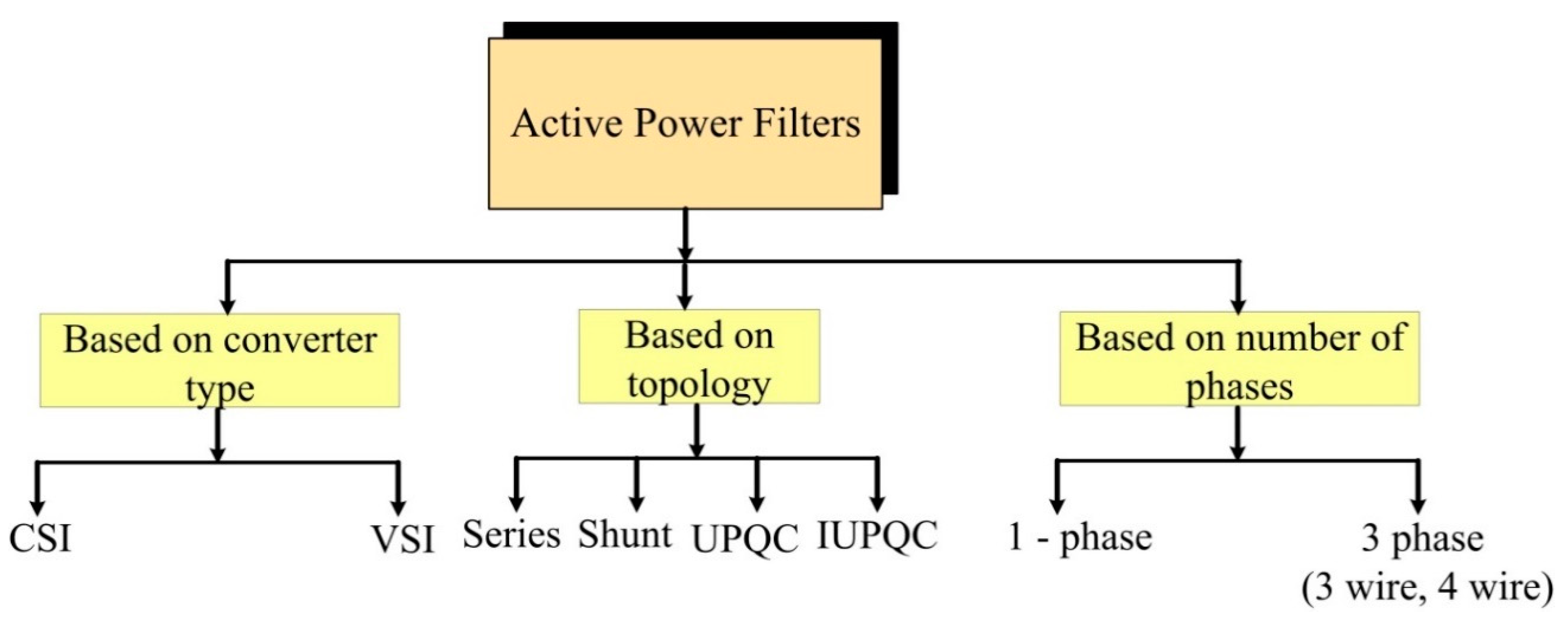
3. Classification of Power Filters
4. Design Configuration of Active Power Filters
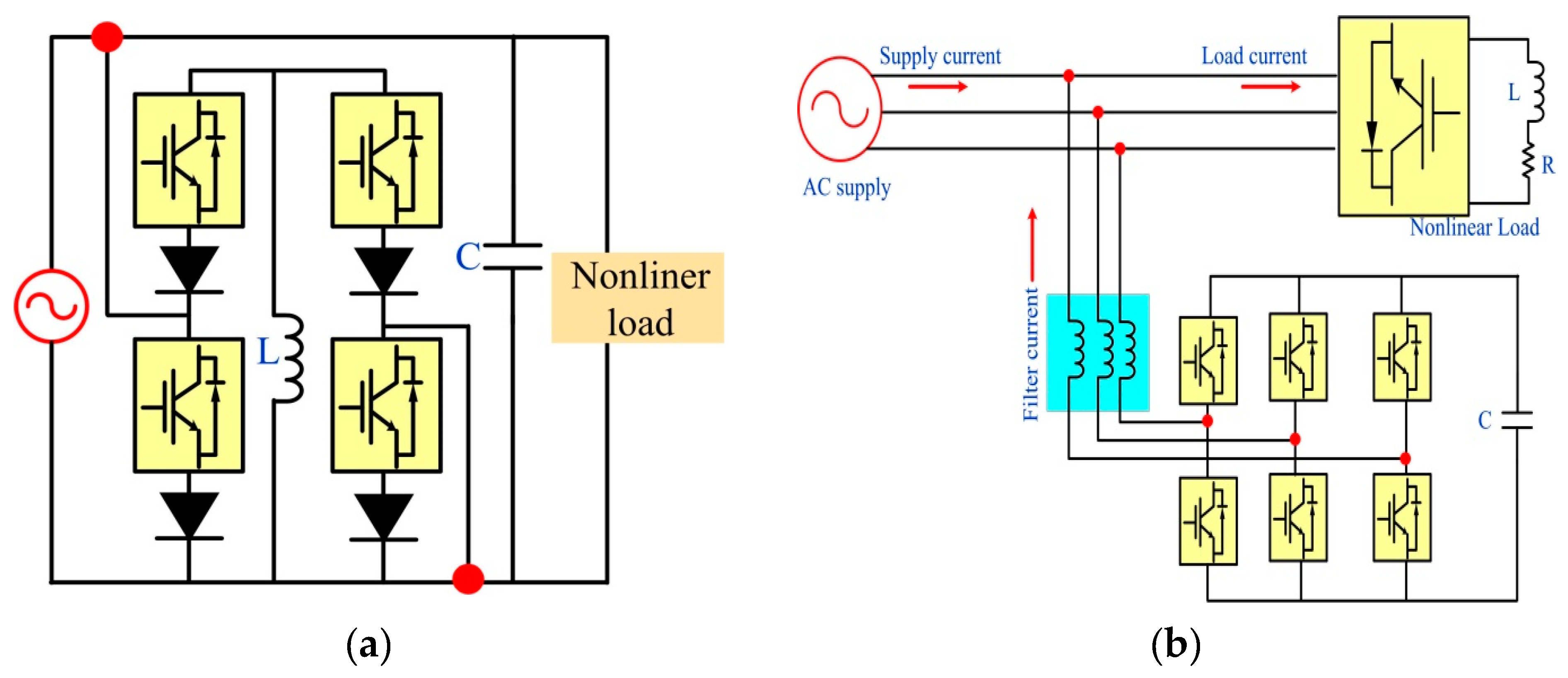
4.1. Topology Type
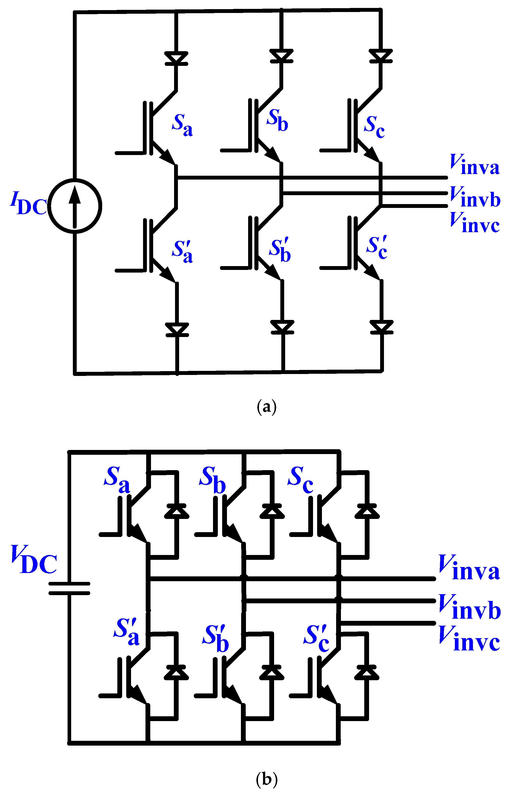
4.2. Converter Type
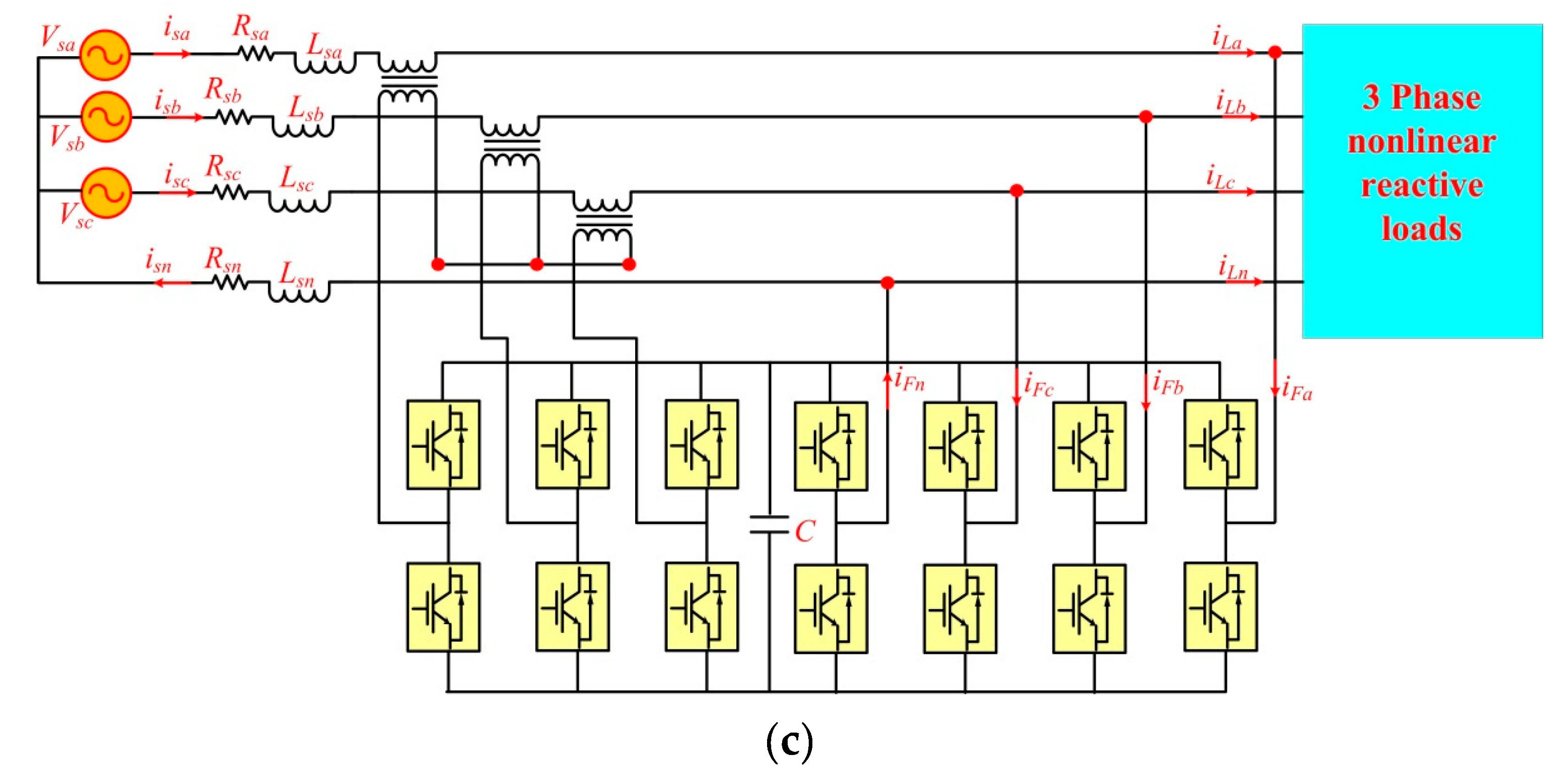
4.3. Based on Phase Connection
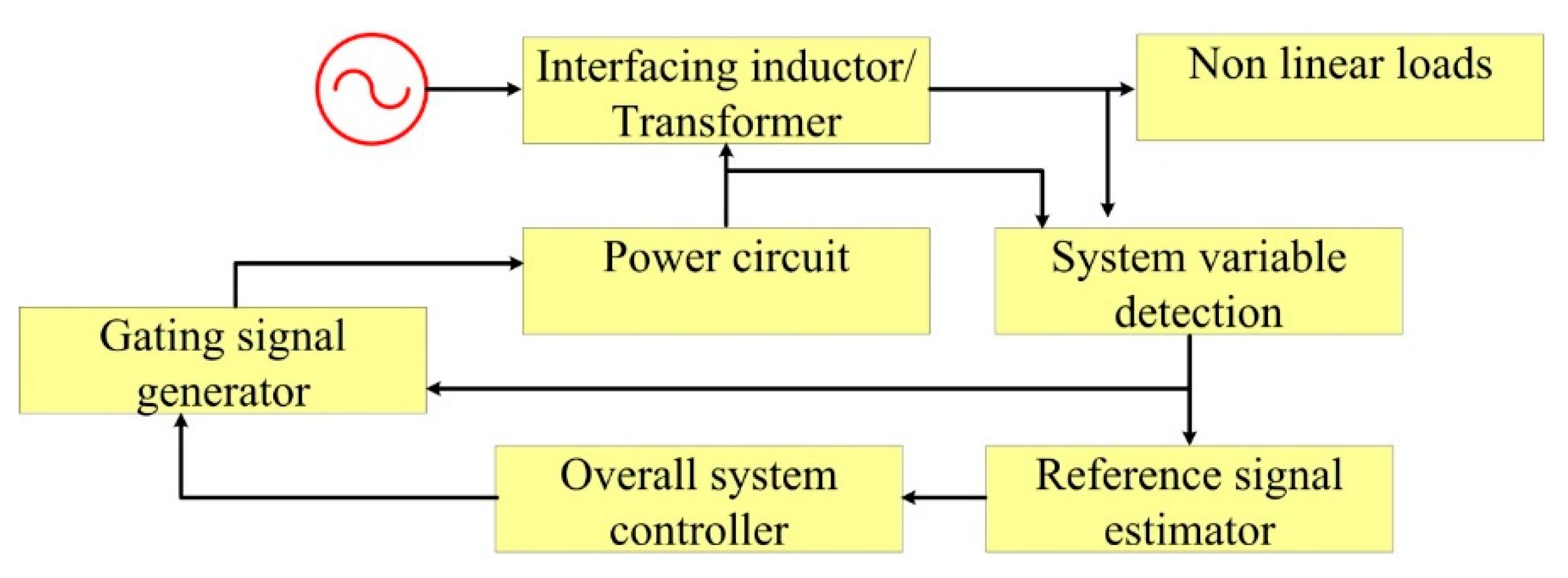
5. Compensation Strategy
5.1. Gating Signal Strategies
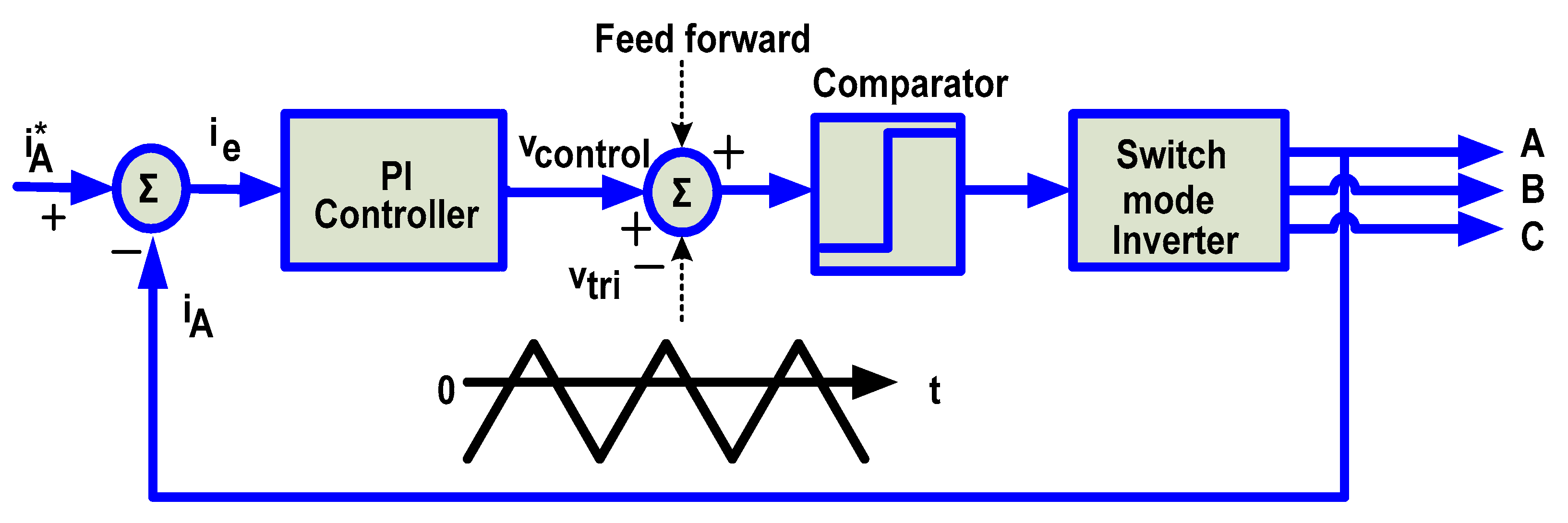
5.1.1. Linear Control Technique
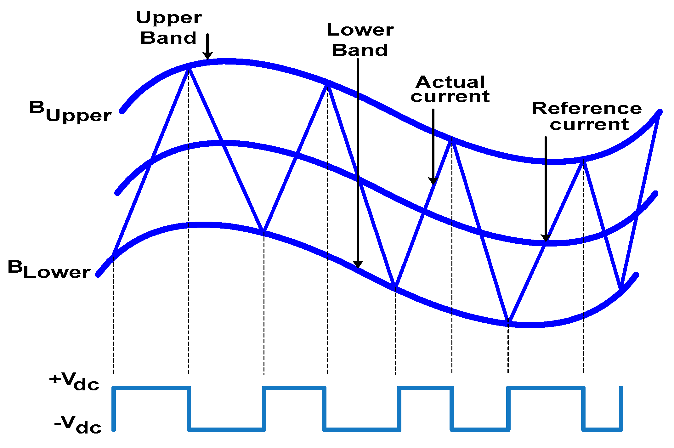
5.1.2. Hysteresis Current Control Technique
5.1.3. Negative Sequence Current Component Control
5.1.4. Sliding Mode Control
5.1.5. One-Cycle Control
5.1.6. Dead-Beat Current Control
5.1.7. Repetitive Control
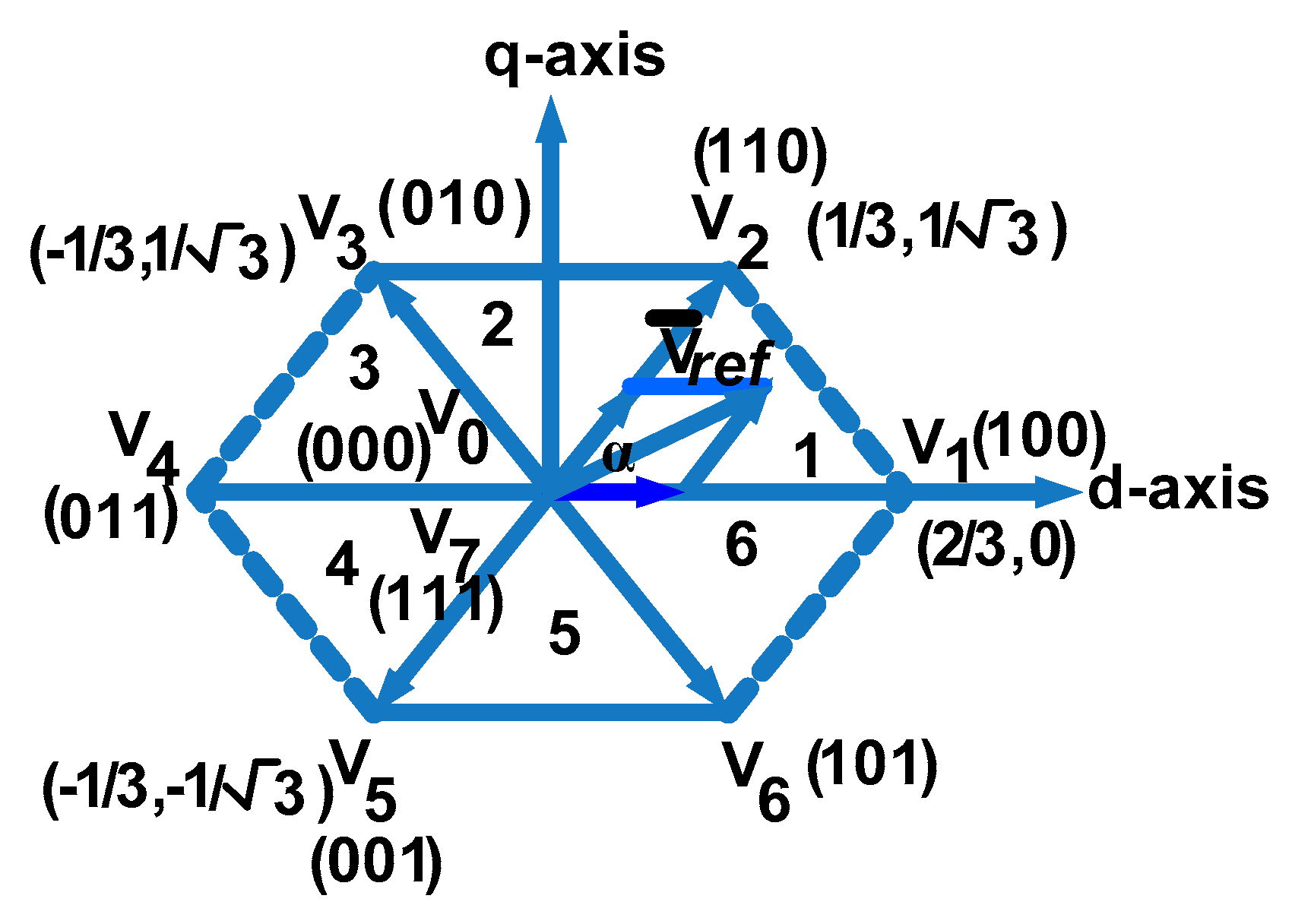
5.1.8. Space Vector Modulation Technique
5.1.9. Predictive Control
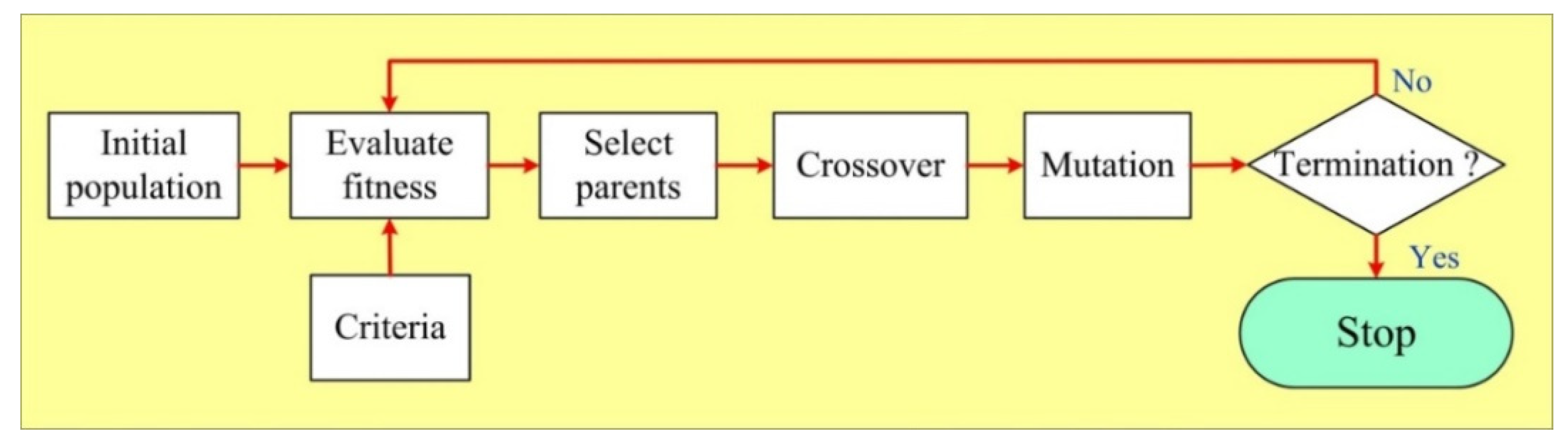
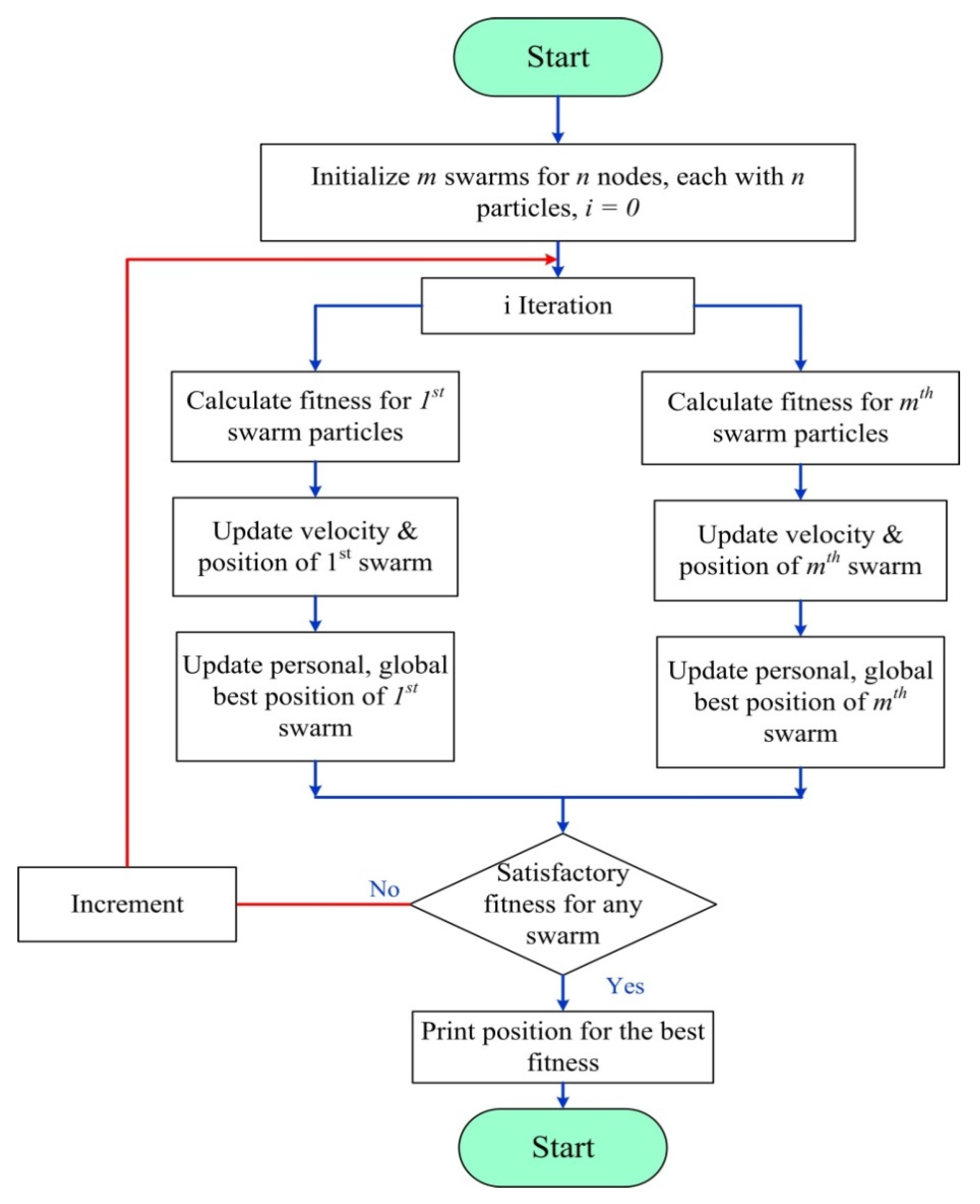
5.1.10. Soft Computing Techniques
5.2. Reference Signal Generation Strategies
- For power calculation and power estimation, it uses a simple and less computationally intensive method.
- It has fast transient response because of less computation.
- It has provisions for large values of the power angle.

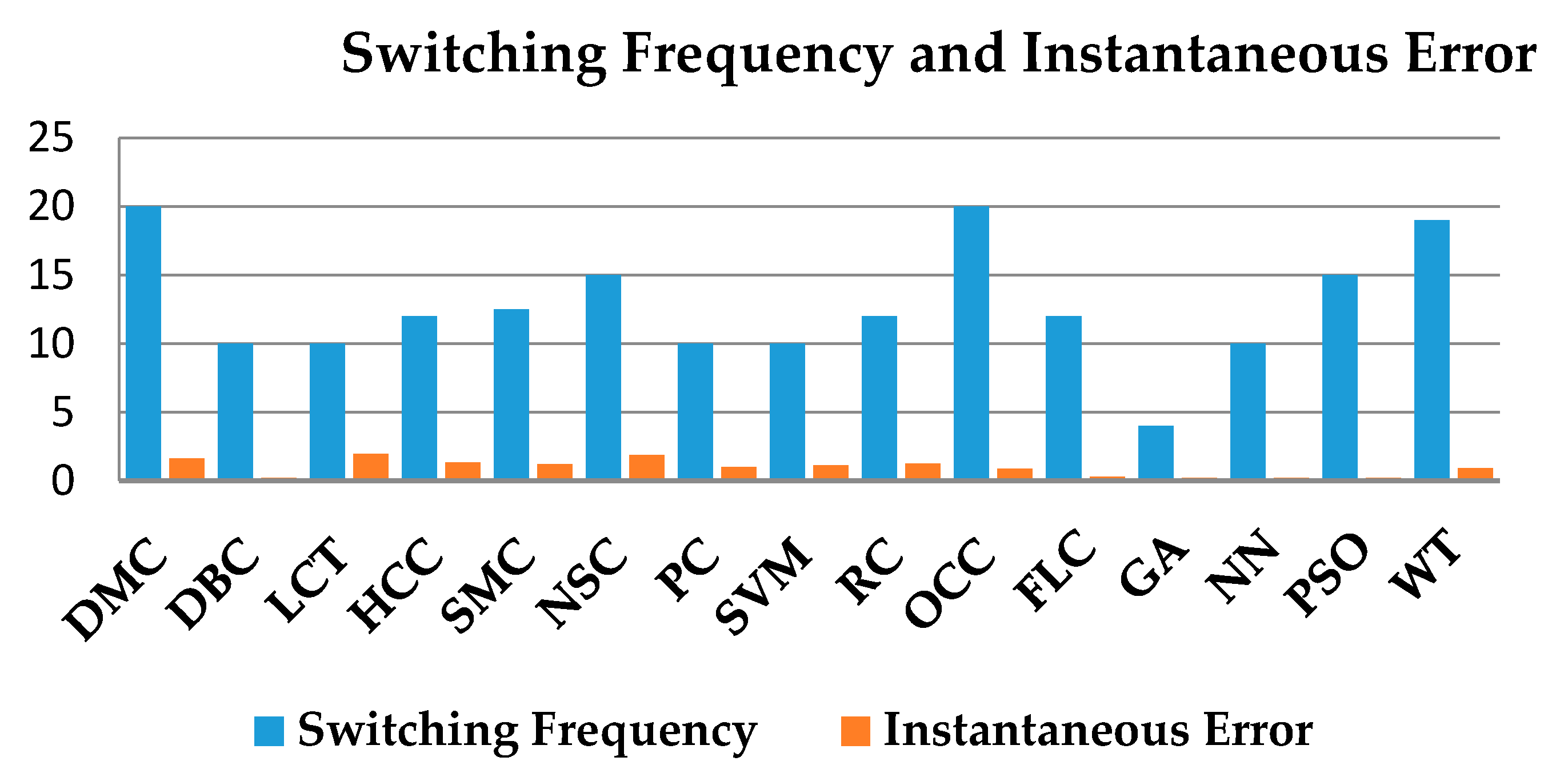
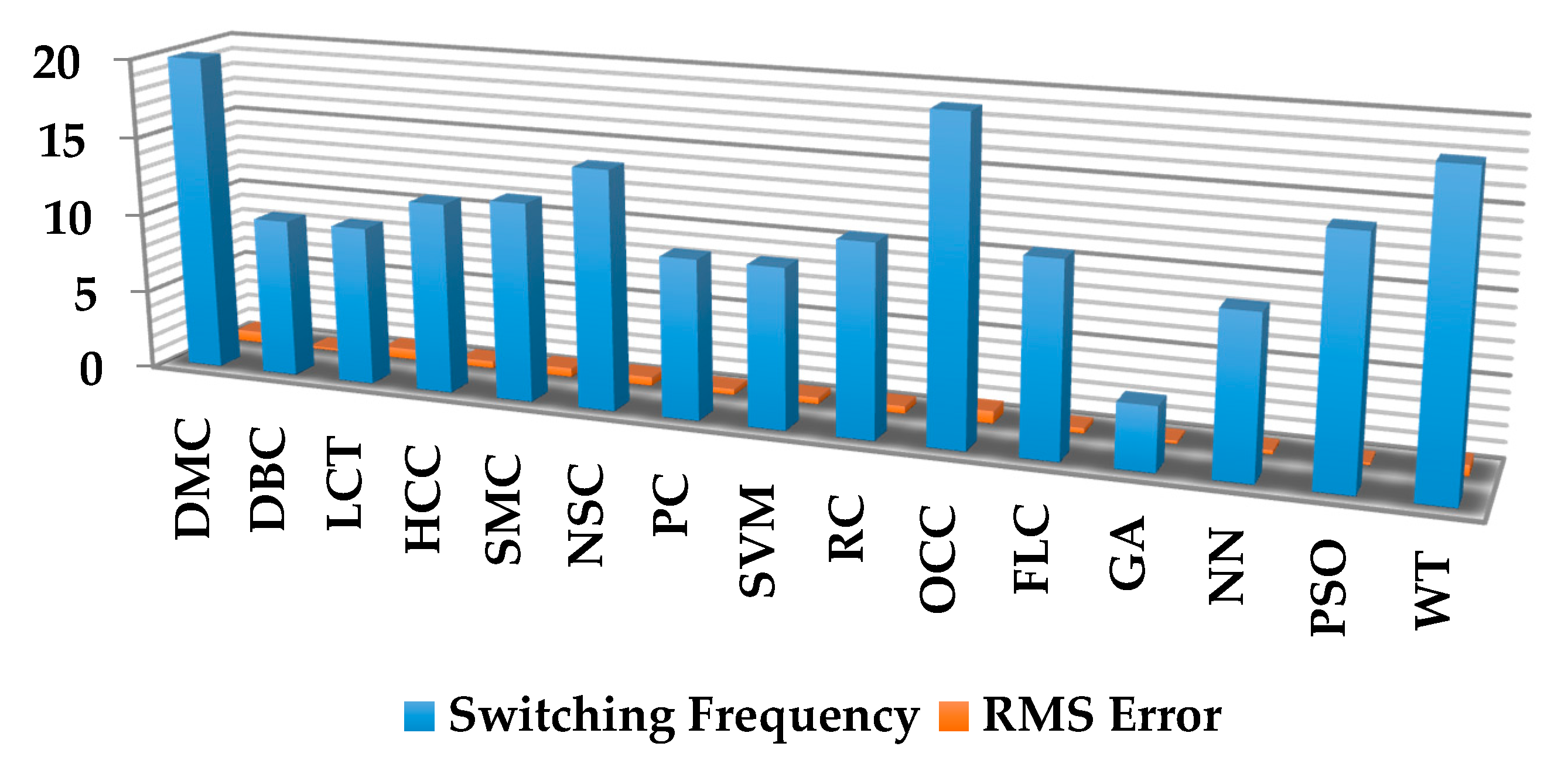
| Compensation Strategy | Features | References |
|---|---|---|
| HCC | Simple in operation; Fast response; Variable switching frequency; No delay time; Harmonic elimination is suitable for a certain range of frequency | [51,57,58] |
| SMC | Simple in operation; Medium response; Variable switching frequency; No delay time | [62,63] |
| NSCC | Simple in operation; Medium response; Constant switching frequency; No delay time | [59,60] |
| DBC | Complex in operation; Medium response; Constant switching frequency; Delay time is medium | [67,68,70] |
| PC | Medium in operation; Medium response; Constant switching frequency; Delay time is long | [79,102] |
| SVM | Operation is quite complicated; Slow response; Constant switching frequency; Delay time is long | [74,77] |
| DMC | Simple in operation; Fast response; Variable switching frequency; No delay time | [71] |
| LCT | Moderate in operation; Fast response; No delay time; Harmonic elimination is suitable for a certain range of frequency | [50] |
| RC | Simple in operation; Medium response; Constant switching frequency; No delay time | [72,73] |
| OCC | Simple in operation; Fast response; Constant switching frequency; No delay time | [65,66] |
| FLC | Medium in operation; Fast response; Constant switching frequency; Delay time is slow; Selective harmonic elimination is not suitable | [82,83] |
| NN | Medium in operation; Selective harmonic elimination is not possible; Fast response; Better accuracy; Delay time is slow; Performance against frequency variation is good; Suitable for unbalanced and distorted supply and unbalanced load | [87,88] |
| GA | Complex in operation; Fast response; Constant switching frequency; No delay time | [85,86] |
| PSO | Complex in operation; Fast response; Constant switching frequency; Delay time is small; Selective harmonic elimination is not suitable | [91,92] |
| WT | More complex in operation; Fast response; Constant switching frequency; Delay time is small; Utilized for harmonic elimination for a particular frequency range | [93,95] |
6. Selection Criteria of PQ Based on Application
- Required level of PQ in input (PF, CF, THD)
- Kind of dc output voltage (constant, variable, etc.)
- Direction of power (unidirectional and bidirectional)
- Behavior of DC output (isolated, non-isolated)
- Requirement of DC output (buck, boost, and buck-boost)
- Required level of PQ in DC output (voltage ripple, voltage regulation, sag and swell)
- Category of dc loads (linear, nonlinear, etc.)
- Economic
- Size and weight
- Efficiency
- Rating
- Reliability
7. Technical and Economic Considerations
8. Trends and Future Developments
8.1. Different Types of Disturbances
- (a)
- Voltage sags are the standards that were characterized by a magnitude at a given duration. Specifically, the 3ϕ characteristics of voltage dips have been underexposed due to the standardized effect. The producers must be conscious about characteristics other than the duration and magnitude.
- (b)
- The distortion in waveform is computed by the spectrum attained over a 200 ms window. Pursuing research for distinct interharmonics considering a high time resolution is an advanced area in the current power system scenario. A fascinating important research challenge is to improve the framework in PQ disturbances not dependent upon any computerization.
8.2. New Sources of Generation
- Performance indicators
- Voltage–magnitude variations
- Emission and resonances in harmonics.
8.3. Remote Identification of Events and Load Transitions and Nonlinear Characteristics
8.4. Time-Varying Harmonic Analysis
8.5. Hardware-In-Loop/Real-Time Digital Simulation
8.6. DC PQ
9. Conclusions
Author Contributions
Funding
Institutional Review Board Statement
Informed Consent Statement
Data Availability Statement
Conflicts of Interest
References
- Dalai, S.; Chatterjee, B.; Dey, D.; Chakravorti, S.; Bhattacharya, K. Rough-Set-Based Feature Selection and Classification for Power Quality Sensing Device Employing Correlation Techniques. IEEE Sens. J. 2012, 13, 563–573. [Google Scholar] [CrossRef]
- Das, B.; Panigrahi, P.K.; Das, S.R.; Mishra, D.P.; Salkuti, S.R. Power quality improvement in a photovoltaic based microgrid integrated network using multilevel inverter. Int. J. Emerg. Electr. Power Syst. 2021. [Google Scholar] [CrossRef]
- Janik, P.; Lobos, T. Automated Classification of Power-Quality Disturbances Using SVM and RBF Networks. IEEE Trans. Power Deliv. 2006, 21, 1663–1669. [Google Scholar] [CrossRef] [Green Version]
- Kwan, K.H.; So, P.L.; Chu, Y.C. An Output Regulation-Based Unified Power Quality Conditioner with Kalman Filters. IEEE Trans. Ind. Electron. 2012, 59, 4248–4262. [Google Scholar] [CrossRef]
- Radil, T.; Ramos, P.M.; Janeiro, F.M.; Serra, A.C. PQ Monitoring System for Real-Time Detection and Classification of Disturbances in a Single-Phase Power System. IEEE Trans. Instrum. Meas. 2008, 57, 1725–1733. [Google Scholar] [CrossRef]
- Singh, B.; Al-Haddad, K.; Chandra, A. A review of active filters for PQ improvement. IEEE Trans. Ind. Electron. 1999, 46, 960–971. [Google Scholar] [CrossRef] [Green Version]
- Mahela, O.P.; Shaik, A.G. Topological aspects of PQ improvement techniques: A comprehensive overview. Renew. Sustain. Energy Rev. 2016, 58, 1129–1142. [Google Scholar] [CrossRef]
- Singh, B.; Jayaprakash, P.; Kothari, D.P.; Chandra, A.; Al Haddad, K. Comprehensive study of DSTATCOM configurations. IEEE Trans. Ind. Inform. 2014, 10, 854–870. [Google Scholar] [CrossRef]
- Wu, J.C.; Jou, H.L.; Wu, K.D.; Hsiao, H.H. Three-phase four-wire hybrid power filter using a smaller power converter. Electr. Power Syst. Res. 2012, 87, 13–21. [Google Scholar] [CrossRef]
- Lee, T.L.; Hu, S.H. Discrete frequency-tuning active filter to suppress harmonic resonances of closed-loop distribution power systems. IEEE Trans. Power Electron. 2011, 26, 137–148. [Google Scholar]
- Das, S.R.; Ray, P.K.; Mohanty, A. Fuzzy sliding mode based series hybrid active power filter for power quality enhancement. Adv. Fuzzy Syst. 2018, 2018, 1309518. [Google Scholar] [CrossRef]
- Liu, Q.; Deng, Y.; He, X. Boost-type inverter-less shunt active power filter for VAR and harmonic compensation. IET Power Electron. 2013, 6, 535–542. [Google Scholar] [CrossRef]
- Barry, M.W.K. Power Quality Primer; Editorial McGraw-Hill: New York, NY, USA, 2000. [Google Scholar]
- Broeck, G.N.V.; Stuyts, J.; Driesen, J. A critical review of power quality standards and definitions applied to DC microgrids. Appl. Energy 2018, 229, 281–288. [Google Scholar] [CrossRef]
- Peng, F.Z.; Akagi, H.; Nabae, A. A new approach to harmonic compensation in power systems-a combined system of shunt passive and series active filters. IEEE Trans. Ind. Appl. 1990, 26, 983–990. [Google Scholar] [CrossRef]
- Kececioglu, O.F.; Acikgoz, H.; Sekkeli, M. Advanced configuration of hybrid passive filter for reactive power and harmonic compensation. SpringerPlus 2016, 5, 1–20. [Google Scholar] [CrossRef] [PubMed] [Green Version]
- Das, J.C. Passive filters-potentialities and limitations. IEEE Trans. Ind. Appl. 2004, 40, 232–241. [Google Scholar] [CrossRef]
- Jovanovic, M.M.; Jang, Y. State-of-the-art, single-phase, active power-factor-correction techniques for high-power applications-an overview. IEEE Trans. Ind. Electron. 2005, 52, 701–708. [Google Scholar] [CrossRef]
- Chaoui, A.; Gaubert, J.P.; Krim, F. PQ improvement using DPC controlled three-phase shunt active filter. Electr. Power Syst. Res. 2010, 80, 657–666. [Google Scholar] [CrossRef]
- Mahanty, R. Large value AC capacitor for harmonic filtering and reactive power compensation. IET Gener. Transm. Distrib. 2008, 2, 876–891. [Google Scholar] [CrossRef]
- Corasaniti, V.F.; Barbieri, M.B.; Arnera, P.L.; Valla, M.I. Hybrid active filter for reactive and harmonics compensation in a distribution network. IEEE Trans. Ind. Electron. 2009, 56, 670–677. [Google Scholar] [CrossRef] [Green Version]
- Ray, P.K.; Das, S.R.; Mohanty, A. Fuzzy-controller-designed-PV-based custom power device for power quality enhancement. IEEE Trans. Energy Convers. 2018, 34, 405–414. [Google Scholar] [CrossRef]
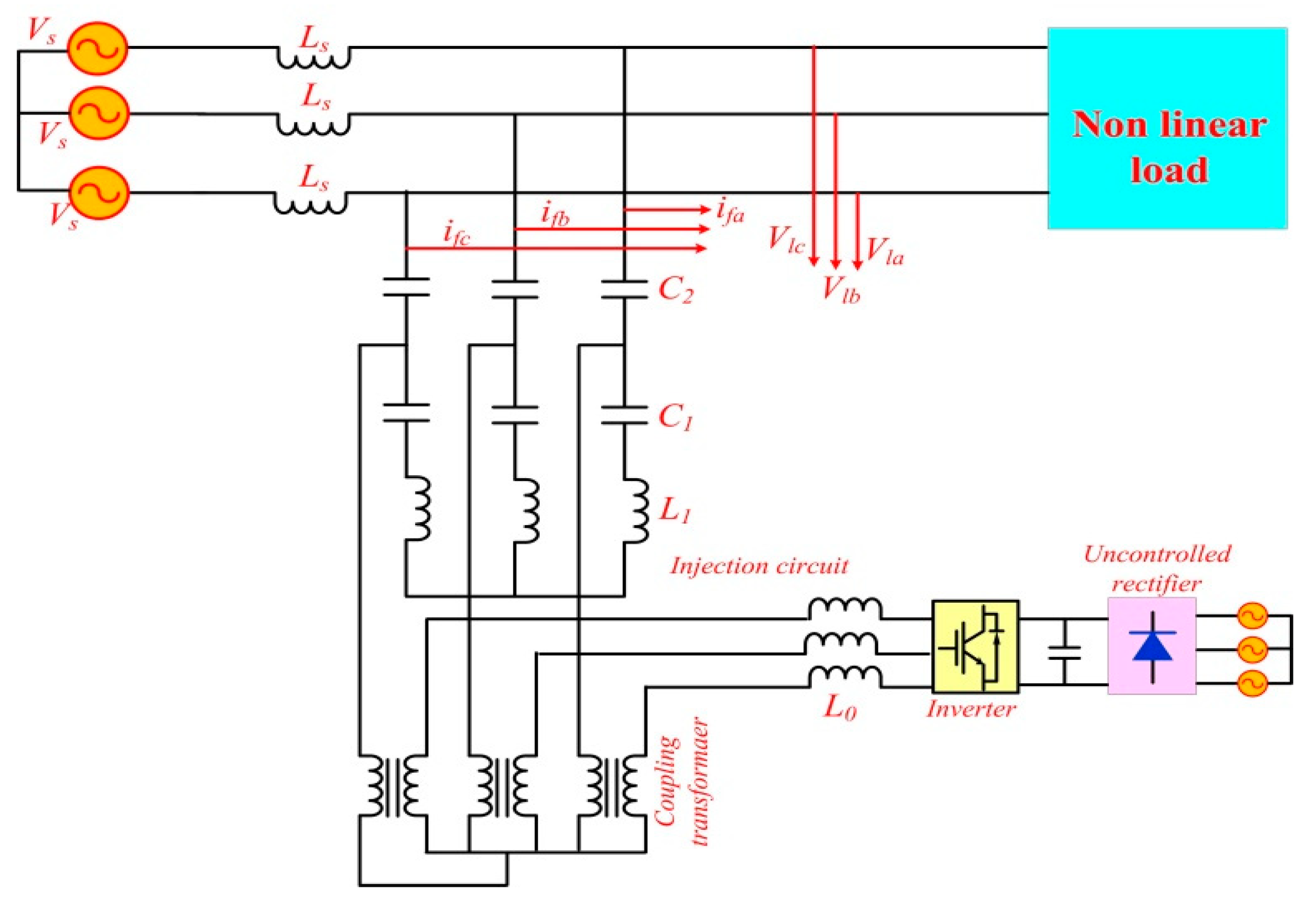
- Luo, A.; Shuai, Z.; Zhu, W.; Shen, Z.J.; Tu, C. Design and application of a hybrid active power filter with injection circuit. IET Power Electron. 2010, 3, 54–64. [Google Scholar] [CrossRef]
- Zhou, X.; Cui, Y.; Ma, Y. Fuzzy Linear Active Disturbance Rejection Control of Injection Hybrid Active Power Filter for Medium and High Voltage Distribution Network. IEEE Access 2021, 9, 8421–8432. [Google Scholar] [CrossRef]
- Akagi, H.; Kondo, R. A transformerless hybrid active filter using a three-level pulsewidth modulation (PWM) converter for a medium-voltage motor drive. IEEE Trans. Power Electron. 2010, 25, 1365–1374. [Google Scholar] [CrossRef]
- Shuai, Z.; Luo, A.; Tu, C.; Liu, D. New control method of injection-type hybrid active power filter. IET Power Electron. 2011, 4, 1051–1057. [Google Scholar] [CrossRef]
- Zobaa, A.F. Optimal multiobjective design of hybrid active power filters considering a distorted environment. IEEE Trans. Ind. Electron. 2014, 61, 107–114. [Google Scholar] [CrossRef] [Green Version]
- Lee, T.L.; Wang, Y.C.; Li, J.C.; Guerrero, J.M. Hybrid active filter with variable conductance for harmonic resonance suppression in industrial power systems. IEEE Trans. Ind. Electron. 2015, 62, 746–756. [Google Scholar] [CrossRef] [Green Version]
- Mikkili, S.; Panda, A.K. PQ issues and solutions–review. Int. J. Emerg. Electr. Power Syst. 2015, 16, 357–384. [Google Scholar]
- Mhawi, E.; Daniyal, H.; Sulaiman, M.H. Advanced Techniques in Harmonic Suppression via Active Power Filter: A Review. Int. J. Power Electron. Drive Syst. 2015, 6, 185–195. [Google Scholar] [CrossRef] [Green Version]
- Heine, P.; Lehtonen, M. Voltage sag distributions caused by power system faults. IEEE Trans. Power Syst. 2003, 18, 1367–1373. [Google Scholar] [CrossRef] [Green Version]
- Tey, L.H.; So, P.L.; Chu, Y.C. Improvement of PQ using adaptive shunt active filter. IEEE Trans. Power Deliv. 2005, 20, 1558–1568. [Google Scholar] [CrossRef]
- Pinto, J.G.; Carneiro, H.; Exposto, B.; Couto, C.; Afonso, J.L. Transformerless series active power filter to compensate voltage disturbances. In Power Electronics and Applications (EPE 2011), Proceedings of the 2011—14th European Conference, Birmingham, UK, 30 August–1 September 2011; IEEE: New York, NY, USA, 2011; pp. 1–6. [Google Scholar]
- Asiminoaei, L.; Aeloiza, E.; Enjeti, P.N.; Blaabjerg, F. Shunt active-power-filter topology based on parallel interleaved inverters. IEEE Trans. Ind. Electron. 2008, 55, 1175–1189. [Google Scholar] [CrossRef]
- Rahmani, S.; Mendalek, N.; Al-Haddad, K. Experimental design of anonlinear control technique for three-phase shunt active powerfilter. IEEE Trans. Ind. Electron. 2010, 57, 3364–3375. [Google Scholar] [CrossRef]
- Khadkikar, V. Enhancing electric PQ using UPQC: A comprehensive overview. IEEE Trans. Power Electron. 2012, 27, 2284–2297. [Google Scholar] [CrossRef]
- Axente, I.; Ganesh, J.N.; Basu, M.; Conlon, M.F.; Gaughan, K. A 12-kVA DSP-controlled laboratory prototype UPQC capable of mitigating unbalance in source voltage and load current. IEEE Trans. Power Electron. 2010, 25, 1471–1479. [Google Scholar] [CrossRef]
- Dos Santos, E.C.; Jacobina, C.B.; Dias, J.A.; Rocha, N. Single-phase to three-phase universal active power filter. IEEE Trans. Power Deliv. 2011, 26, 1361–1371. [Google Scholar] [CrossRef]
- Dass, P.M.; Fathima, A.P. Grid integration of Photovoltaic System Interfaced with Artificial Intelligence based Modified Universal Power Quality conditioning system. J. Phys. Conf. Ser. 2020, 1716, 012010. [Google Scholar] [CrossRef]
- Bhattacharya, S.; Divan, D.M. Hybrid Series Active/Parallel Passive Power Line Conditioner with Controlled Harmonic Injection. U.S. Patent 5,465,203, 7 November 1995. [Google Scholar]
- Kim, Y.S.; Kim, J.S.; Ko, S.H. Three-phase three-wire series active power filter, which compensates for harmonics and reactive power. IEE Proc. Electr. Power Appl. 2004, 151, 276–282. [Google Scholar] [CrossRef]
- Khadkikar, V.; Chandra, A.; Barry, A.O.; Nguyen, T.D. PQ enhancement utilising single-phase unified PQ conditioner: Digital signal processor-based experimental validation. IET Power Electron. 2011, 4, 323–331. [Google Scholar] [CrossRef]
- Singh, B.; Singh, B.N.; Chandra, A.; Al-Haddad, K.; Pandey, A.; Kothari, D.P. A review of single-phase improved PQ AC-DC converters. IEEE Trans. Ind. Electron. 2003, 50, 962–981. [Google Scholar] [CrossRef] [Green Version]
- Singh, B.; Bhuvaneswari, G.; Arya, S.R. Review on PQ solution technology. Asian Power Electron. J. 2012, 6, 19–27. [Google Scholar]
- Büyük, M.; Tan, A.; Tümay, M.; Bayındır, K.Ç. Topologies, generalized designs, passive and active damping methods of switching ripple filters for voltage source inverter: A comprehensive review. Renew. Sustain. Energy Rev. 2016, 62, 46–69. [Google Scholar] [CrossRef]
- Garcia Campanhol, L.B.; Oliveira da Silva, S.A.; Goedtel, A. Application of shunt active power filter for harmonic reduction and reactive power compensation in three-phase four-wire systems. IET Power Electron. 2014, 7, 2825–2836. [Google Scholar] [CrossRef]
- Melin, P.E.; Espinoza, J.R.; Zargari, N.R.; Moran, L.A.; Guzman, J.I. A novel multi-level converter based on current source power cell. In Proceedings of the Power Electronics Specialists Conference 2008 (PESC 2008), Rhodes, Greece, 15–19 June 2008; pp. 2084–2089. [Google Scholar]
- Lam, C.S.; Wong, M.C.; Han, Y.D. Hysteresis current control of hybrid active power filters. IET Power Electron. 2012, 5, 1175–1187. [Google Scholar] [CrossRef] [Green Version]
- Kale, M.; Ozdemir, E. An adaptive hysteresis band current controller for shunt active power filter. Electr. Power Syst. Res. 2005, 73, 113–119. [Google Scholar] [CrossRef]
- Barrero, F.; Martínez, S.; Yeves, F.; Mur, F.; Martínez, P.M. Universal and reconfigurable to UPS active power filter for line conditioning. IEEE Trans. Power Deliv. 2003, 18, 283–290. [Google Scholar] [CrossRef]
- Maciel, L.F.; Morales, J.L.; Gaona, D.C.; Pimentel, J.G. A study of a three-phase four-wire shunt active power filter for harmonics mitigation. In Proceedings of the 2018 IEEE International Autumn Meeting on Power, Electronics and Computing (ROPEC), Ixtapa, Mexico, 14–16 November 2018; pp. 1–6. [Google Scholar]
- Ucar, M.; Ozdemir, E. Control of a 3-phase 4-leg active power filter under non-ideal mains voltage condition. Electr. Power Syst. Res. 2008, 78, 58–73. [Google Scholar] [CrossRef]
- Buso, S.; Fasolo, S.; Malesani, L.; Mattavelli, P. A dead-beat adaptive hysteresis current control. IEEE Trans. Ind. Appl. 2000, 36, 1174–1180. [Google Scholar] [CrossRef]
- Zeng, J.; Yu, C.; Qi, Q.; Yan, Z.; Ni, Y.; Zhang, B.L.; Chen, S.; Wu, F.F. A novel hysteresis current control for active power filter with constant frequency. Electr. Power Syst. Res. 2004, 68, 75–82. [Google Scholar] [CrossRef]
- Swain, S.; Panda, P.C.; Subudhi, B.D. Three phase shunt Active Power Filter using a new Weighted Adaptive Hysteresis Band Current Controller. In Proceedings of the 2014 International Conference on Circuit, Power and Computing Technologies (ICCPCT 2014), Nagercoil, India, 20–21 March 2014; pp. 781–786. [Google Scholar]
- Rodriguez, P.; Candela, J.I.; Luna, A.; Asiminoaei, L.; Teodorescu, R.; Blaabjerg, F. Current harmonics cancellation in three-phase four-wire systems by using a four-branch star filtering topology. IEEE Trans. Power Electron. 2009, 24, 1939–1950. [Google Scholar] [CrossRef] [Green Version]
- Luo, A.; Shuai, Z.; Zhu, W.; Fan, R.; Tu, C. Development of hybrid active power filter based on the adaptive fuzzy dividing frequency-control method. IEEE Trans. Power Deliv. 2009, 24, 424–432. [Google Scholar] [CrossRef]
- Suresh, Y.; Panda, A.K.; Suresh, M. Real-time implementation of adaptive fuzzy hysteresis-band current control technique for shunt active power filter. IET Power Electron. 2012, 5, 1188–1195. [Google Scholar] [CrossRef] [Green Version]
- Xu, W.; Dian, R.J.; Mu, C.X. Novel negative sequence current detection and control strategy for H-bridge three-level active power filter. In Applied Superconductivity and Electromagnetic Devices (ASEMD), Proceedings of the IEEE International Conference, Shanghai, China, 20–23 November 2015; IEEE: New York, NY, USA, 2015; pp. 85–86. [Google Scholar]
- Dian, R.; Xu, W.; Mu, C. Improved negative sequence current detection and control strategy for h-bridge three-level active power filter. IEEE Trans. Appl. Supercond. 2016, 26, 1–5. [Google Scholar] [CrossRef]
- Ray, A.S.; Bhattacharya, A. Improved tracking of shunt active power filter by sliding mode control. Int. J. Electr. Power Energy Syst. 2016, 78, 916–925. [Google Scholar]
- Fei, J.; Zhang, S.; Zhou, J. Adaptive Sliding Mode Control of Single-Phase Shunt Active Power Filter. Math. Probl. Eng. 2012, 2012, 1–22. [Google Scholar] [CrossRef]
- Ghamri, A.; Benchouia, M.T.; Golea, A. Sliding-mode control based three-phase shunt active power filter: Simulation and experimentation. Electr. Power Compon. Syst. 2012, 40, 383–398. [Google Scholar] [CrossRef]
- Fei, J.; Liu, N.; Hou, S.; Fang, Y. Neural Network Complementary Sliding Mode Current Control of Active Power Filter. IEEE Access 2021, 9, 25681–25690. [Google Scholar] [CrossRef]
- Jin, T.; Smedley, K.M. Operation of one-cycle controlled three-phase active power filter with unbalanced source and load. IEEE Trans. Power Electron. 2006, 21, 1403–1412. [Google Scholar] [CrossRef]
- Qiao, C.; Jin, T.; Smedley, K.M. One-cycle control of three-phase active power filter with vector operation. IEEE Trans. Ind. Electron. 2004, 51, 455–463. [Google Scholar] [CrossRef]
- Yuan, X.; Merk, W.; Stemmler, H.; Allmeling, J. Stationary-frame generalized integrators for current control of active power filters with zero steady-state error for current harmonics of concern under unbalanced and distorted operating conditions. IEEE Trans. Ind. Appl. 2002, 38, 523–532. [Google Scholar] [CrossRef]
- Montero, M.I.; Cadaval, E.R.; Gonzalez, F.B. Comparison of control strategies for shunt active power filters in three-phase four-wire systems. IEEE Trans. Power Electron. 2007, 22, 229–236. [Google Scholar] [CrossRef]
- Borisov, K.; Ginn, H.L. Multifunctional VSI based on a novel fortescue reference signal generator. IEEE Trans. Ind. Electron. 2009, 57, 1002–1007. [Google Scholar] [CrossRef]
- Malesani, L.; Mattavelli, P.; Buso, S. Robust dead-beat current control for PWM rectifiers and active filters. In Proceedings of the Conference Record of 1998 IEEE Industry Applications Conference, Thirty-Third IAS Annual Meeting, St. Louis, MO, USA, 12–15 October 1998; Volume 2, pp. 1377–1384. [Google Scholar]
- Narongrit, T.; Areerak, K.L.; Areerak, K.N. The comparison study of current control techniques for active power filters. World Acad. Sci. Eng. Technol. 2011, 60, 471–476. [Google Scholar]
- Xiao, Z.; Chen, Y.; Deng, X. A Shunt Active Power Filter with Enhanced Dynamic performance using Dual-Repetitive Controller and Predictive Compensation. Int. J. Power Electron. Drive Syst. 2013, 3, 209. [Google Scholar] [CrossRef]
- Grino, R.; Cardoner, R.; Costa-Castelló, R.; Fossas, E. Digital repetitive control of a three-phase four-wire shunt active filter. IEEE Trans. Ind. Electron. 2007, 54, 1495–1503. [Google Scholar] [CrossRef]
- Rathnakumar, D.; LakshmanaPerumal, J.; Srinivasan, T. A new software implementation of space vector PWM. In Proceedings of the IEEE Southeastcon, Ft. Lauderdale, FL, USA, 8–10 April 2005; pp. 131–136. [Google Scholar]
- Qi, Q.; Yu, C.; Wai, C.K.; Ni, Y. Modeling and simulation of a STATCOM system based on 3-level NPC inverter using dynamic phasors. In Proceedings of the IEEE Power Engineering Society General Meeting, Denver, CO, USA, 6–10 June 2004; pp. 1559–1564. [Google Scholar]
- Saeedifard, M.; Nikkhajoei, H.; Iravani, R. A space vector modulated STATCOM based on a three-level neutral point clamped converter. IEEE Trans. Power Deliv. 2007, 22, 1029–1039. [Google Scholar] [CrossRef]
- Ahmed, I.; Borghate, V.B. Simplified space vector modulation technique for seven-level cascaded H-bridge inverter. IET Power Electron. 2014, 7, 604–613. [Google Scholar] [CrossRef]
- Chen, D.; Xie, S. Review of the control strategies applied to active power filters. In Proceedings of the 2004 IEEE International Conference on Electric Utility Deregulation, Restructuring and Power Technologies, Hong Kong, China, 5–8 April 2004; Volume 2, pp. 666–670. [Google Scholar]
- Kouro, S.; Cortés, P.; Vargas, R.; Ammann, U.; Rodríguez, J. Model predictive control—A simple and powerful method to control power converters. IEEE Trans. Ind. Electron. 2009, 56, 1826–1838. [Google Scholar] [CrossRef]
- Bhattacharya, A.; Chakraborty, C. A shunt active power filter with enhanced performance using ANN-based predictive and adaptive controllers. IEEE Trans. Ind. Electron. 2011, 58, 421–428. [Google Scholar] [CrossRef]
- Kumar, P.; Mahajan, A. Soft computing techniques for the control of an active power filter. IEEE Trans. Power Deliv. 2009, 24, 452–461. [Google Scholar] [CrossRef]
- Suresh, M.; Anup, K.P. Types-1 and -2 fuzzy logic controllers-based shunt active filter Id-Iq control strategy with different fuzzy mem-bership functions for PQ improvement using RTDS hardware. IET Power Electron. 2013, 6, 818–833. [Google Scholar]
- Suresh, M.; Anup, K.P. Real-time implementation of PI and fuzzy logic controllers based shunt active filter control strategies for PQ improvement. Electr. Power Energy Syst. 2012, 43, 1114–1126. [Google Scholar]
- Chau, M.; Luo, A.; Chau, V. PID-Fuzzy Control Method with Time Delay Compensation for Hybrid Active Power Filter with Injection Circuit. Int. J. Comput. Appl. 2011, 36, 15–21. [Google Scholar]
- Khalid, S.; Dwivedi, B.; Singh, B. New Optimum Three-Phase Shunt Active Power Filter based on Adaptive Tabu Search and Genetic Algorithm using ANN control in unbalanced and distorted supply conditions. Elektr. J. Electr. Eng. 2012, 14, 9–14. [Google Scholar]
- Khalid, S.; Dwivedi, B. Simulation and Performance Based Comparison of GA-Fuzzy-ANN Based Shunt Active Power Filter for PQ Improvement in High Frequency Aircraft System. J. Aerspace Eng. Technol. 2013, 3, 62–70. [Google Scholar]
- Das, S.R.; Ray, P.K.; Mohanty, A. Improvement of Power Quality using Advanced Artificial Neural Network Algorithm. In Proceedings of the 2018 IEEE International Conference on Power Electronics, Drives and Energy Systems (PEDES), Madras, India, 18–21 December 2018; pp. 1–6. [Google Scholar]
- Kumar, V.S.; Kavitha, D.; Kalaiselvi, K.; Kannan, P.S. Harmonic mitigation and power factor improvement using fuzzy logic and neural network controlled active power filter. J. Electr. Eng. Technol. 2008, 3, 520–527. [Google Scholar] [CrossRef] [Green Version]
- Atiqi Mohd Zainuri, M.A.; Mohd Radzi, M.A.; Soh, A.C.; Mariun, N.; Rahim, N.A.; Hajighorbani, S. Fundamental Active Current Adaptive Linear Neural Networks for Photovoltaic Shunt Active Power Filters. Energies 2016, 9, 397. [Google Scholar] [CrossRef] [Green Version]
- Arya, S.R.; Singh, B. Neural network based conductance estimation control algorithm for shunt compensation. IEEE Trans. Ind. Inform. 2014, 10, 569–577. [Google Scholar] [CrossRef]
- Patnaik, S.S.; Panda, A.K. Particle swarm optimization and bacterial foraging optimization techniques for optimal current harmonic mitigation by employing active power filter. Appl. Comput. Intell. Soft Comput. 2012, 2012, 897127. [Google Scholar] [CrossRef] [Green Version]
- Patnaik, S.S.; Panda, A.K. Real-time performance analysis and comparison of various control schemes for particle swarm optimization-based shunt active power filters. Int. J. Electr. Power Energy Syst. 2013, 52, 185–197. [Google Scholar] [CrossRef]
- Das, S.R.; Ray, P.K.; Sahoo, A.K.; Ramasubbareddy, S.; Babu, T.S.; Kumar, N.M.; Haes Alhelou, H.; Siano, P. Performance of Hybrid Filter in a Microgrid Integrated Power System Network Using Wavelet Techniques. Appl. Sci. 2020, 10, 6792. [Google Scholar] [CrossRef]
- Hirve, S.; Chatterjee, K.; Fernandes, B.G.; Imayavaramban, M.; Dwari, S. PLL-less active power filter based on onecycle control for compensating unbalanced loads in threephase four-wire system. IEEE Trans. Power Deliv. 2007, 22, 2457–2465. [Google Scholar] [CrossRef] [Green Version]
- Das, S.R.; Mishra, A.K.; Ray, P.K.; Mohanty, A.; Mishra, D.K.; Li, L.; Hossain, M.J.; Mallick, R.K. Advanced wavelet transform based shunt hybrid active filter in PV integrated power distribution system for power quality enhancement. IET Energy Syst. Integr. 2020, 2, 331–343. [Google Scholar]
- Dey, P.; Mekhilef, S. Current controllers of active power filter for power quality improvement: A technical analysis. Automatika 2015, 56, 42–54. [Google Scholar] [CrossRef] [Green Version]
- Büyük, M.; İnci, M.; Tan, A.; Tümay, M. Improved instantaneous power theory based current harmonic extraction for unbalanced electrical grid conditions. Electr. Power Syst. Res. 2019, 177, 106014. [Google Scholar] [CrossRef]
- Patel, A.; Mathur, H.D.; Bhanot, S. A new SRF-based power angle control method for UPQC-DG to integrate solar PV into grid. Int. Trans. Electr. Energy Syst. 2019, 29, 2667. [Google Scholar] [CrossRef] [Green Version]
- Chen, C.I.; Lan, C.K.; Chen, Y.C.; Chen, C.H. Adaptive Frequency-Based Reference Compensation Current Control Strategy of Shunt Active Power Filter for Unbalanced Nonlinear Loads. Energies 2019, 12, 3080. [Google Scholar] [CrossRef] [Green Version]
- Munir, H.M.; Zou, J.; Xie, C.; Li, K.; Younas, T.; Guerrero, J.M. Direct harmonic voltage control strategy of shunt active power filters suitable for microgrid applications. J. Power Electron. 2019, 19, 265–277. [Google Scholar]
- Sujitha, M.; Padmab, S. Optimization of harmonics with active power filter based on ADALINE neural network. Microprocess. Microsyst. 2020, 73, 102976. [Google Scholar] [CrossRef]
- Zhang, X.; Chen, J.; Zhang, G.; Wang, L.; Qiu, R.; Liu, Z. An active oscillation compensation method to mitigate high-frequency harmonic instability and low-frequency oscillation in railway traction power supply system. IEEE Access 2018, 6, 70359–70367. [Google Scholar] [CrossRef]
- Wong, L.A.; Ramachandaramurthy, V.K.; Taylor, P.; Ekanayake, J.B.; Walker, S.L.; Padmanaban, S. Review on the optimal placement, sizing and control of an energy storage system in the distribution network. J. Energy Storage 2019, 21, 489–504. [Google Scholar] [CrossRef]
- Shen, L.; Cheng, Q.; Cheng, Y.; Wei, L.; Wang, Y. Hierarchical control of DC micro-grid for photovoltaic EV charging station based on flywheel and battery energy storage system. Electr. Power Syst. Res. 2020, 179, 106079. [Google Scholar] [CrossRef]
- Melo, I.D.; Pereira, J.L.; Variz, A.M.; Ribeiro, P.F. Allocation and sizing of single tuned passive filters in three-phase distribution systems for power quality improvement. Electr. Power Syst. Res. 2020, 180, 106128. [Google Scholar] [CrossRef]
- Ferreira, S.C.; Gonzatti, R.B.; Pereira, R.R.; da Silva, C.H.; da Silva, L.B.; Lambert-Torres, G. Finite control set model predictive control for dynamic reactive power compensation with hybrid active power filters. IEEE Trans. Ind. Electron. 2017, 65, 2608–2617. [Google Scholar] [CrossRef]
- Biricik, S.; Ozerdem, O.C.; Redif, S.; Dincer, M.S. New hybrid active power filter for harmonic current suppression and reactive power compensation. Int. J. Electron. 2016, 103, 1397–1414. [Google Scholar] [CrossRef]
- Azri, M.; Rahim, N. Design analysis of low-pass passive filter in single-phase grid-connected transformerless inverter. In Proceedings of the 2011 IEEE Conference on Clean Energy and Technology (CET), Kuala Lumpur, Malaysia, 20–23 November 2011; pp. 348–353. [Google Scholar]
- Santiprapan, P.; Booranawong, A. An Adaptive Repetitive Controller for an Active Power Filter in Three-Phase Four-Wire Systems. IET Power Electron. 2020, 13, 2756–2766. [Google Scholar] [CrossRef]
- Rastogi, M.; Mohan, N.; Edris, A. Hybrid-active filtering of harmonic currents in power systems. IEEE Trans. Power Deliv. 1995, 10, 1994–2000. [Google Scholar] [CrossRef]
- Mohammadi, H.; Varjani, A.; Mokhtari, H. Multiconverter unified power-quality conditioning system: MC-UPQC. IEEE Trans. Power Deliv. 2009, 24, 1679–1686. [Google Scholar] [CrossRef]
- Karanki, S.; Mishra, M.; Kumar, B. Particle swarm optimization-based feedback controller for unified power-quality conditioner. IEEE Trans. Power Deliv. 2010, 25, 2814–2824. [Google Scholar] [CrossRef]
- Ribeiro, P.; Gu, I.; Duque, C. Trends, challenges and opportunities in power quality research. Eur. Trans. Electr. Power 2010, 20, 13–18. [Google Scholar]
- Das, S.R.; Ray, P.K.; Mishra, A.K.; Mohanty, A. Performance of PV integrated multilevel inverter for PQ enhancement. Int. J. Electron. 2021, 108, 945–982. [Google Scholar] [CrossRef]
- Gupta, K.K.; Ranjan, A.; Bhatnagar, P.; Sahu, L.K.; Jain, S. Multilevel inverter topologies with reduced device count: A review. IEEE Trans. Power Electron. 2015, 31, 135–151. [Google Scholar] [CrossRef]
- Singh, B.; Kumar, R. A comprehensive survey on enhancement of system performances by using different types of FACTS controllers in power systems with static and realistic load models. Energy Rep. 2020, 6, 55–79. [Google Scholar] [CrossRef]
- Brinkel, N.B.G.; Gerritsma, M.K.; AlSkaif, T.A.; Lampropoulos, I.; Voorden, A.M.; Fidder, H.A.; Sark, W.G.J.H.M. Impact of rapid PV fluctuations on power quality in the low-voltage grid and mitigation strategies using electric vehicles. Int. J. Electr. Power Energy Syst. 2020, 118, 105741. [Google Scholar] [CrossRef]
- Butt, O.M.; Muhammad, Z.; Butt, T.M. Recent advancement in smart grid technology: Future prospects in the electrical power network. Ain Shams Eng. J. 2021, 12, 687–695. [Google Scholar] [CrossRef]


| Disturbances | Harmonics Standards |
|---|---|
| Harmonic environment | IEC 1000-2-1/2 |
| Compatibility limits | IEEE 519 IEC 1000-3-2/4 (555) |
| Harmonic measurement | IEC 1000-4-7/13/15 |
| Harmonic practices | IEEE 519A IEC 1000-5-5 |
| Component heating | ANSI IEEE C57.110 IEC 1000-3-6 |
| Under-sag-conditions | IEEE 1250 IEC 38, 1000-2-4 |
| Sag measurement | IEC 1000-4-1/11 |
| Sag mitigation | IEEE 446, 1100, 1159 IEC 1000-5-X |
| Over surge environment | ANSI IEEE C62.41 IEC-1000-3-7 |
| Fuse blowing/upsets | ANSI C84.1 IEC 1000-2-5 |
| Compatibility levels | IEC 3000-3-X |
| Surge measurement | ANSI IEEE C62.45 IEC 1000-4-1/2/4/5/12 |
| Surge protection | IEC 1000-5-X |
| Insulation breakdown | IEC 664 |
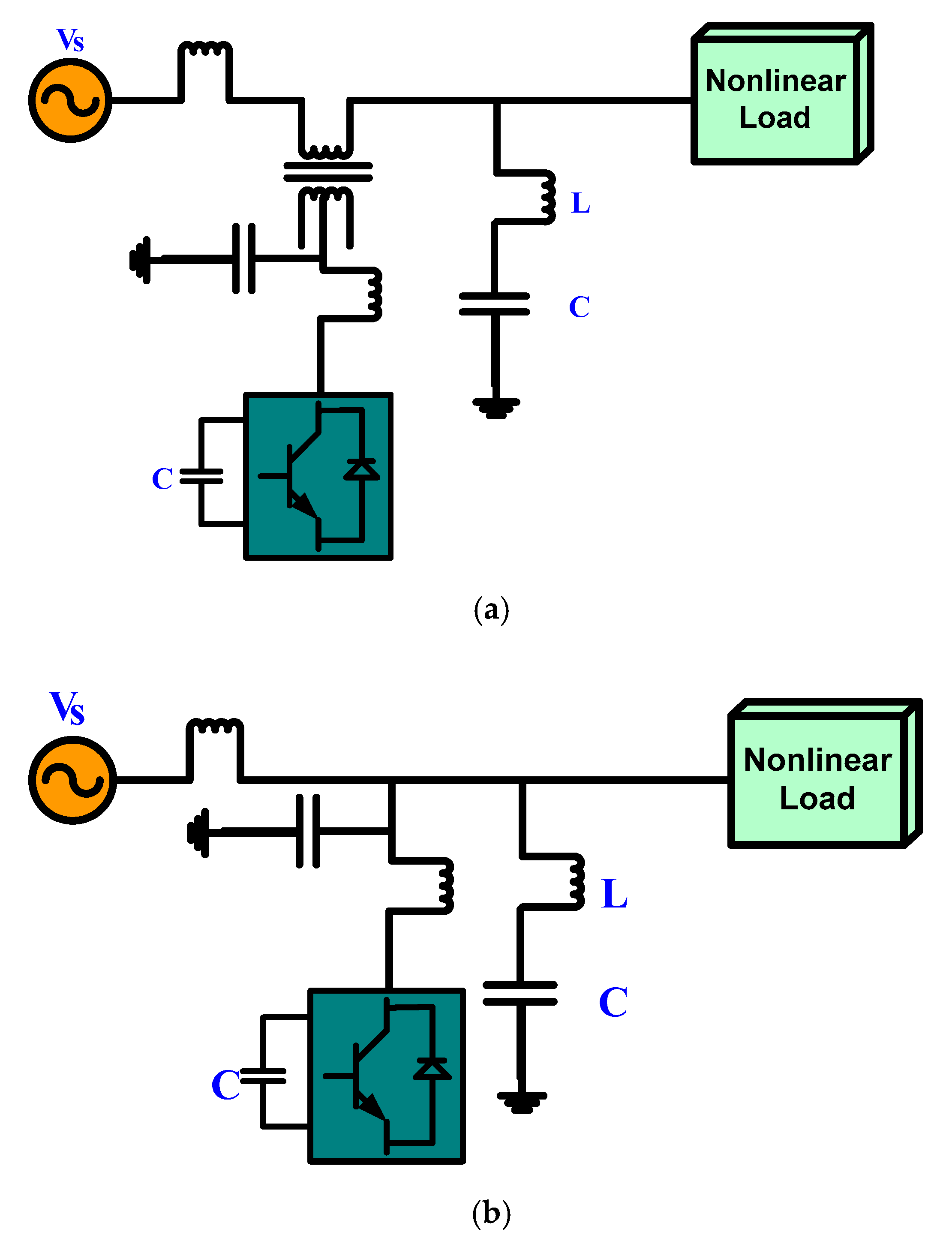
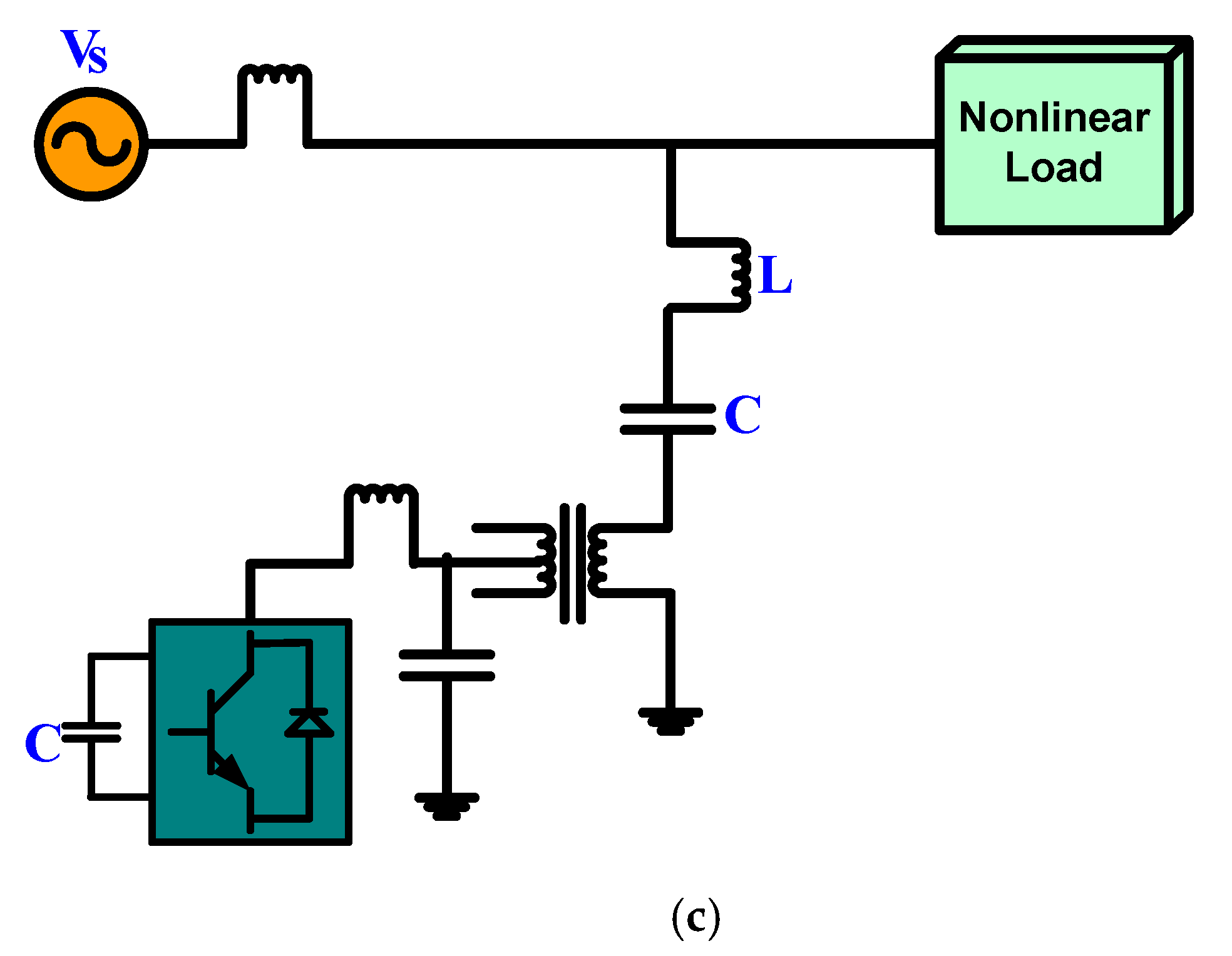
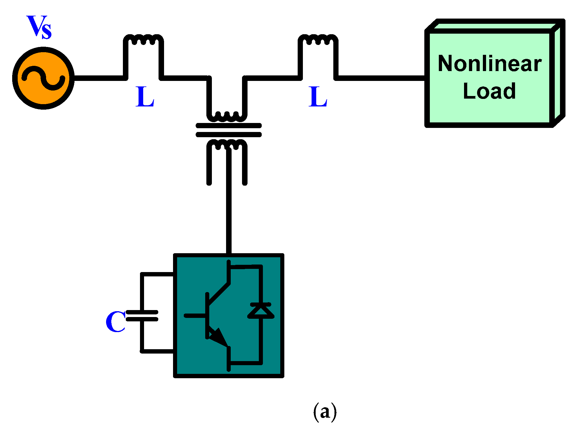
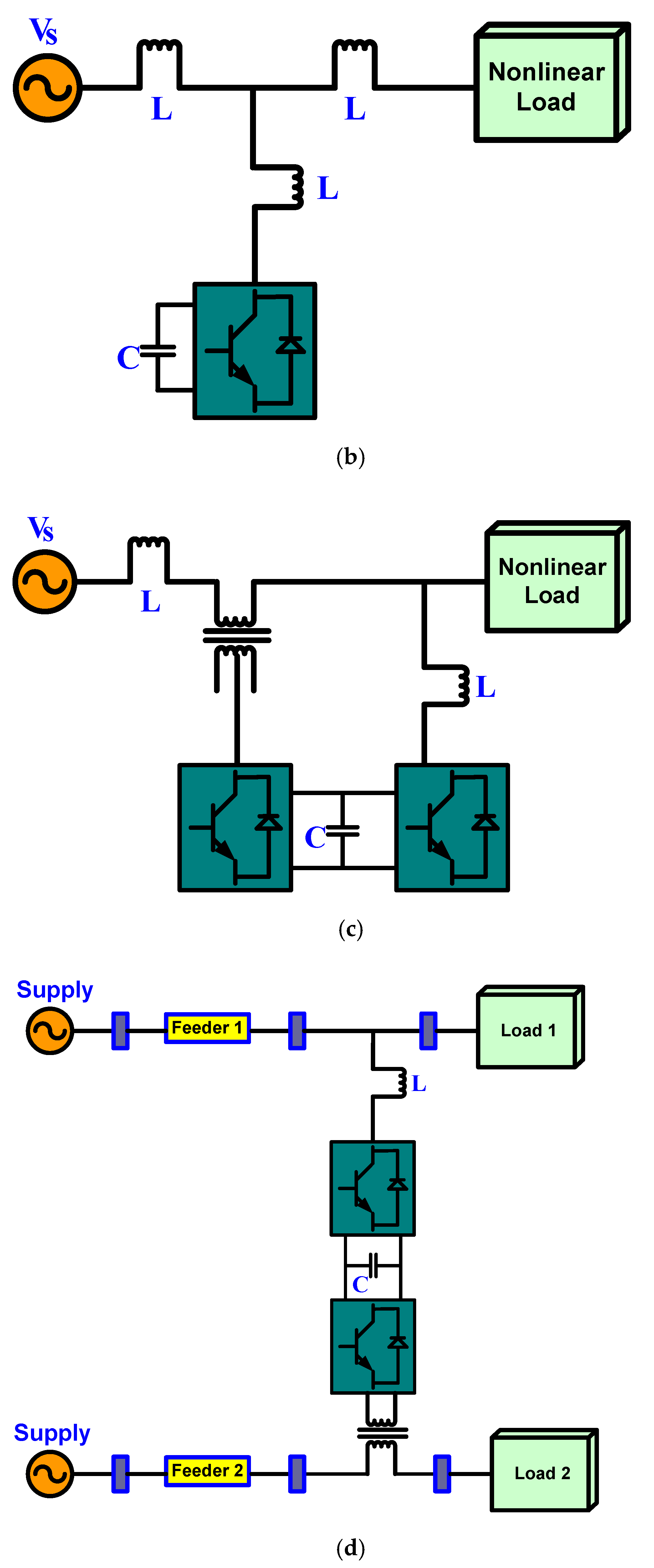
| Topology of HAPF | Applications and Brief Remarks | Configuration of Circuit |
|---|---|---|
| SEAPF + shunt PF |
| Refer to Figure 3a |
| SAPF + shunt PF |
| Refer to Figure 3b |
| APF connected in series with shunt PF |
| Refer to Figure 3c |
| Comparison Criteria | CSI | VSI |
|---|---|---|
| Phases | 3-phase | l- and 3-phase |
| Operation | Inserts currents at PCC for suppressing harmonics current at the load end | Perform through a superimposed current-control loop to generate the desired signal |
| Power applications | Medium-power ratings | Low/medium-power ratings |
| Control strategy | Complex | Simple |
| Speed of response in ms | Medium (−1) | Fast (−0.1) |
| No of active devices | 6 switches, 6 diodes | L-phase: 4 switches, 14 diodes 3-phase: 6 switches, 6 diodes |
| Switching frequency, Hz | −2–5 | −20–30 |
| DC energy storing capacity | DC inductor (−100 mh) | DC capacitor (-4700-9ooovf) |
| The DC-link voltage or current | (1.3–1.5) × rated Supply current | (1.3–1.5) × rated Supply voltage |
| AC components | Na | Na |
| AC voltage ratings | Na | Na |
| Voltage or current discontinuities | Currents with higher ratings and change (+idc and −idc) | Voltage with higher ratings and change (+vdc and −vdc) |
| Associated loss | Total power loss is high. | Total power loss is low. |
| Input parameter | The current input is constant and changeable. An inductor is connected across the CSI. This inductor is large, high cost, and provides more loss. | Voltage input is constant. The capacitor is connected across the CSI. This capacitor is small, economical, and is effective energy storage. |
| Power source | The input of a CSI is a dc voltage source with high impedance. | The input of VSI is a dc voltage source with low impedance. |
Publisher’s Note: MDPI stays neutral with regard to jurisdictional claims in published maps and institutional affiliations. |
© 2021 by the authors. Licensee MDPI, Basel, Switzerland. This article is an open access article distributed under the terms and conditions of the Creative Commons Attribution (CC BY) license (https://creativecommons.org/licenses/by/4.0/).
Share and Cite
Das, S.R.; Ray, P.K.; Sahoo, A.K.; Ramasubbareddy, S.; Babu, T.S.; Kumar, N.M.; Elavarasan, R.M.; Mihet-Popa, L. A Comprehensive Survey on Different Control Strategies and Applications of Active Power Filters for Power Quality Improvement. Energies 2021, 14, 4589. https://doi.org/10.3390/en14154589
Das SR, Ray PK, Sahoo AK, Ramasubbareddy S, Babu TS, Kumar NM, Elavarasan RM, Mihet-Popa L. A Comprehensive Survey on Different Control Strategies and Applications of Active Power Filters for Power Quality Improvement. Energies. 2021; 14(15):4589. https://doi.org/10.3390/en14154589
Chicago/Turabian StyleDas, Soumya Ranjan, Prakash Kumar Ray, Arun Kumar Sahoo, Somula Ramasubbareddy, Thanikanti Sudhakar Babu, Nallapaneni Manoj Kumar, Rajvikram Madurai Elavarasan, and Lucian Mihet-Popa. 2021. "A Comprehensive Survey on Different Control Strategies and Applications of Active Power Filters for Power Quality Improvement" Energies 14, no. 15: 4589. https://doi.org/10.3390/en14154589