
Stability Analysis of Shunt Active Power Filter with Predictive Closed-Loop Control of Supply Current


1
Department of Ship Automation, Faculty of Electrical Engineering, Gdynia Maritime University, 81-225 Gdynia, Poland
2
Department of Power Electronics and Electrical Machines, Faculty of Electrical and Control Engineering, Gdansk University of Technology, 80-233 Gdańsk, Poland
*
Author to whom correspondence should be addressed.
Energies 2021, 14(8), 2208; https://doi.org/10.3390/en14082208
Submission received: 16 March 2021
/
Revised: 10 April 2021
/
Accepted: 12 April 2021
/
Published: 15 April 2021
(This article belongs to the Special Issue Active Power Filters and Power Quality)
Abstract
:This paper presents a shunt active power filter connected to the grid via an LCL coupling circuit with implemented closed-loop control. The proposed control system allows selective harmonic currents compensation up to the 50th harmonic with the utilization of a model-based predictive current controller. As the system is fully predictive, it provides high effectiveness of the harmonic reduction, which is proved by waveforms achieved in performed tests. On the other hand, the control system is prone to loss of stability. Therefore, the paper is focused on the stability analysis of the discussed control system with the additional outer control loop of the supply current with predictive control of this current. The conducted stability analysis encompasses the assessment of system stability as a function of the coupling circuit parameter identification accuracy, whose values are implemented in the current controller, as well as parameters such as the sampling frequency and proportional-integral (PI) controller coefficients. The obtained results show that the ranges of the LCL circuit parameter identification accuracy for which the system remains stable are relatively wide. However, the most effective compensation of the supply current distortion is achieved for the parameters identified correctly, and the greatest impact on the compensation quality has the value of L1 inductance.
1. Introduction
The active power filter (APF) is a proven tool for power quality problems as it provides controllable and very effective harmonic currents compensation. On account of this, such a device has become more and more popular, which is reflected by the numerous research works on its control strategies published in scientific journals.
APFs can be classified into three types on the basis of their topology and connection to the power grid. The series APF, which is connected to the grid via a coupling transformer, constitutes a controlled voltage source and is utilized to directly mitigate voltage distortion [1,2]. However, the shunt APF, being connected in parallel between the supply and non-linear loads via a passive circuit, compensates directly for current distortion [3,4,5,6,7,8,9,10,11,12,13,14,15,16,17,18,19,20,21,22,23,24,25,26,27,28,29,30] and also, indirectly, the grid voltage. It acts as a controlled current source and is characterized by more merits in comparison to the series APF, which has made it widely used in industrial applications. The hybrid APF [31,32], holding the advantages of both passive and active power filters, combines improved performance and cost-effective solutions. There are two prominent configurations of the hybrid APF: a combination of the series APF and a shunt passive filter and a combination of the shunt APF and a shunt passive filter.
There are two main control strategies for the shunt APF in accordance with the control theory: feedforward open-loop control [8,11,17,19,24,25,26] and feedback closed-loop control [3,4,5,6,7,9,10,11,12,15,16,18,21,22,23,30]. They are based on the selection of the current around the point of common coupling (PCC), which is used in the control. The load current measurement is used to determine the set current in the open-loop system, while the supply current measurement is utilized in the closed-loop control. This control system is more complex than open-loop control as it requires the use of an outer control loop of the upstream current with simultaneous control of this current. It is less popular than the open-loop control structure on account of the fact that it is more prone to loss of stability. On the other hand, it ensures a higher level of harmonic currents compensation. Another less common control strategy is based on the measurement of voltage in the PCC. The reference current, which is proportional to voltage harmonic components, ensures compensation of distortions regardless of whether they come from the load or the supply side [28,29].
Determination of current harmonics to be compensated is significant and established on their detection with the utilization of the particular techniques in either the time or the frequency domain. The former approach encompasses methods such as instantaneous reactive power theory (p-q theory) [8,13,14,15], stationary reference frame theory [12] or synchronous rotational reference frame theory relying on Park’s transformation (d-q transformation) [3,7,18,22,25], whereas the latter comprises Fourier transform techniques (FFT, DFT) [11,20] as well as their variations [4,5,6,7,11]. Apart from this, harmonic currents compensation can be broadband or selective, often comprising harmonic current orders equal to 6k ± 1 as they are the most common existing in three-phase plants. There are also new approaches for this issue, such as the one presented in [32], which shows a hybrid APF defining the reference current on the basis of the sliding mode control. Another interesting study case is presented in [18], which proposes rectifying the problem in the electromagnetic compatibility of power electronics equipment by developing the APF’s high control accuracy based on d-q control.
A crucial element of the APF control structure is a current controller due to the fact that it determines the quality of the reference current tracking. There is a wide range of various current controllers, among which one can distinguish a simple proportional-integral (PI) controller [3,4,7,10,15,17,18], a proportional-resonance (PR) controller [13,16,23], a deadbeat controller [12] and a model-based predictive controller (MPC) [8,20]. The challenges for current controllers include maximizing the harmonic currents compensation, correction of delays between the measurements and control and cooperation with the coupling circuit. In APFs, an LCL circuit has to be used as a coupling circuit due to its facility to mitigate current ripples resulting from the pulse modulation of the converter. However, it causes a resonance hazard. One solution to this issue is applying the active damping method [16,23,33]. The literature [16] presents the combination of using a current controller based on PR units with phase compensation along with the inverter-side current feedback active damping to attenuate the LCL resonance peak. Another approach for developing a current controller is shown in [22], which presents a current controller consisting of n parallel-connected PI controllers. There is a coupling circuit in the form of the inductance which does not cause a risk of resonance, but it is less effective in attenuating the switching ripples. However, although the mentioned solutions are well developed, they do not compensate the delays resulting from the discrete control system. Achieving this is possible with the utilization of a predictive current controller. The MPC of the control system proposed in this paper not only compensates for the mentioned delays but also fully blocks the resonance of the LCL circuit and is characterized by great dynamics of operation. Using this controller with the additional outer control loop of the upstream current in a control system of an APF is a novelty. Nevertheless, the application of the additional outer control loop for the upstream current with the predictive control of this current implies the necessity of applying prediction also when determining the reference current, which makes it more complex. Another problematic issue resulting from this outer current feedback loop is its proneness to loss of stability in the system. Therefore, defining the stability margins for this control system is of high importance.
The stability analysis of the proposed system has not been presented in the literature. Generally, the stability analysis is an important issue in control systems which is why it is shared by some researchers [8,22,23,24,28]. Not only does it present the impact of particular parameters on the system stability but it also allows defining the range of their possible changes in such a way as to avoid the loss of stability. There are very little papers focusing on the stability analysis of an APF with external closed-loop control from the supply current. Existing ones, such as [22,23], do not involve predictive solutions; therefore, such an analysis seems to be important to introduce. Although the significance of such an analysis is considerable, conducting it can be complicated. Therefore, the introduction of some simplification is often demanded, especially in systems with complex structures.
The main subject of this paper is the stability analysis of a three-phase shunt APF with an implemented control system with an additional predictive outer control loop of the upstream current with predictive control of this current. This includes defining transfer functions of the system and examining the impact of the sampling period value, control system parameters and the accuracy of coupling circuit parameter identification on the system stability.
The paper is divided into five sections. Section 2 presents a circuit structure, a description of the implemented control and the parameters of the discussed system. Then, sample waveforms to illustrate the operation and a harmonic currents compensation level realized by the proposed shunt APF are presented. Section 3 focuses on the stability analysis of the system with the defining partial and overall transfer functions of the control system. Section 4 depicts root locations as a function of the changes in the particular control system’s parameter values and defines the margins of the system stability for this system. The paper ends with a brief conclusion summarizing the significant contributions of the work in Section 5.
2. Proposed Control System
The presented system is a shunt APF which is connected in parallel between the supply and the load. Its circuit structure along with detailed parameters and proposed control strategy is described below.
2.1. System Description
The system under study is a three-phase, three-wire low-voltage power grid with a non-linear load connected to the grid via LL inductors. The load consists of a three-phase rectifier with the RL load on the DC side of this converter. The implemented shunt APF comprises a two-level voltage source inverter (VSI), which acts as a controlled current source, connected to the grid between the source and the load in the PCC via a coupling circuit. An LCL circuit was applied to ensure the attenuation of current ripples which are caused by the impulse operation of the converter. The proposed main circuit topology, which is a diagram of the tested system, is shown in Figure 1. The parameters in the figure indicate the following: iu—upstream current, id—downstream current, i1—L1 current, i2 = ik—L2 current. The values of the circuit’s parameters along with the parameters of the control are presented in Table 1.
The selection of the LCL circuit parameter values as well as the value of the sampling period was performed in accordance with the methodology proposed in [8].
2.2. Control Structure
The proposed control system is a predictive closed-loop control of the shunt APF which utilizes the outer control loop of the upstream current with simultaneous realization of the control of this current. Its main units include the uDC controller, which serves the superordinate function in the system, the predictive set current determination unit, the predictive current controller and the space vector pulse width modulation (SVPWM) modulator. The system’s block diagram is presented in Figure 2.
The implemented control algorithm is developed in the orthogonal stationary reference frame projected on the complex plane α-jβ with the usage of the Clarke transform with power invariance. The application of prediction demands the use of the predictive current controller, which provides correction of delays between the feedbacks and control, prediction of the supply voltage and prediction of the reference current.
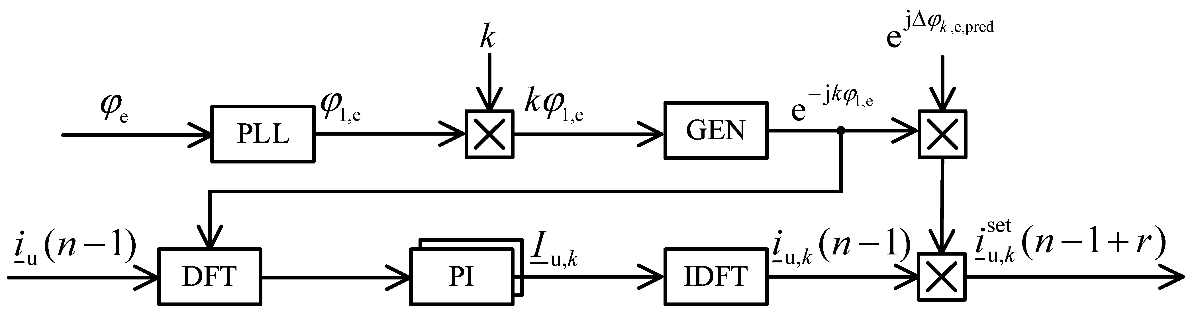
The outer control loop of the upstream current is predictive and determines the APF reference current in a selective manner. It was set to allow compensating harmonic currents whose orders are equal to ±(6k ± 1), up to the 50th harmonic. The particular reference harmonic current calculation, which is shown as a block diagram in Figure 3, includes the discrete Fourier transform (DFT), PI control, inverse discrete Fourier transform (IDFT) and prediction. The outer PI controllers, which are independent for each of the compensated current harmonics, control the complex amplitudes of these current harmonics to be equal to zero (separately, their orthogonal real and imaginary components), which are constant for the quasi-steady state of the compensated non-linear loads. Therefore, the task of these outer PI controllers is to completely eliminate the compensated current harmonics from the upstream current thanks to the action of its integral parts. The dynamics of these outer loop PI current controllers determine only the APF response time for changes in the power of compensated loads. They substantially improve the APF current compensation effectiveness in quasi-steady states, regardless of the dynamics of the inner current controller. Particular symbols appearing in the figure, not mentioned before, indicate: φe,1—the instantaneous phase angle of the supply voltage fundamental harmonic, k—the order of harmonic current to be compensated, r—prediction horizon, n—sample number.
The resultant reference current is a superposition of the currents of individual harmonics determined in accordance with the diagram shown in Figure 3. The applied prediction horizon is equal to 3 on account of the fact that LCL is a third-order circuit. It means that zero error of the set current is possible to achieve in a discrete control system in three control steps, which corresponds to three sampling periods Ts.
2.3. Sample Waveforms
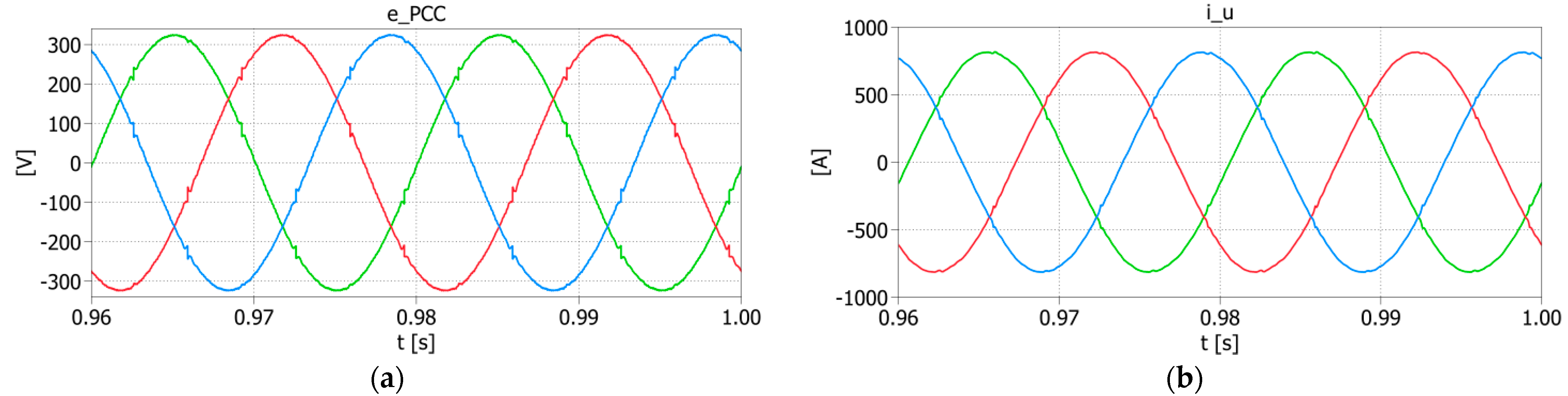
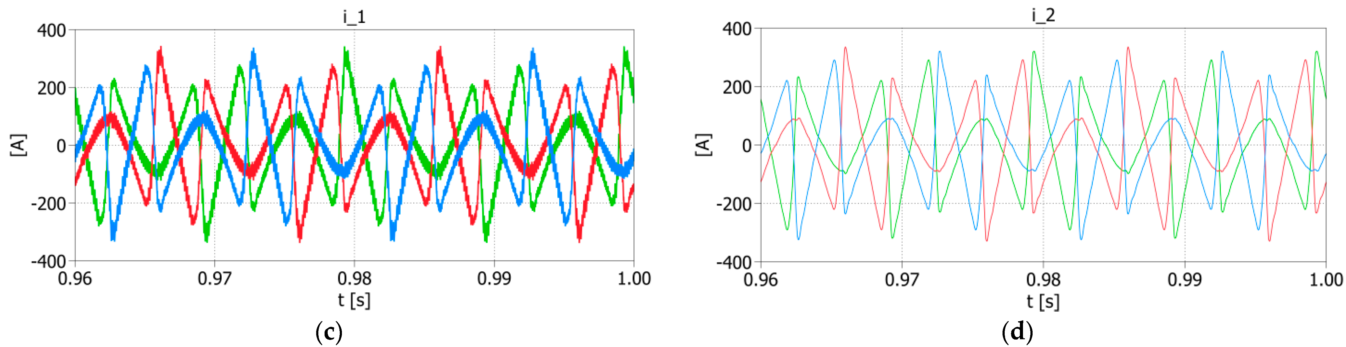
The discussed system, whose structure is presented in Figure 1, was examined in the simulation tests conducted in the PLECS software. The control system, shown in Figure 2, and the diagram for the outer control loop of the upstream current, determining the APF’s reference current, which is depicted in Figure 3, were implemented as an algorithm written in the C programming language. The simulation tests were conducted taking into consideration the feedback path from the upstream current, delays between the feedback and the control and the non-linearities resulting from the impulse operation of the converter. The presented results, which are depicted in Figure 4 and Figure 5, were achieved for the system’s parameters given in Table 1. Figure 4 shows waveforms in the PCC when there is no harmonic compensation in the system, whilst Figure 5 presents the transients when the APF is enabled.
The above results prove that the proposed control strategy provided a high level of harmonic current limitation, which resulted, consequently, in voltage harmonics mitigation. THDi decreased about twenty-seven times, whereas THDu decreased almost four and a half times. Moreover, waveforms depicted in Figure 5c,d reflect the effect of the influence of the LCL circuit on the system. The ripples contained in the APF current observed in Figure 5c and related to pulse modulation were reduced almost completely, which can be noticed in Figure 5d.
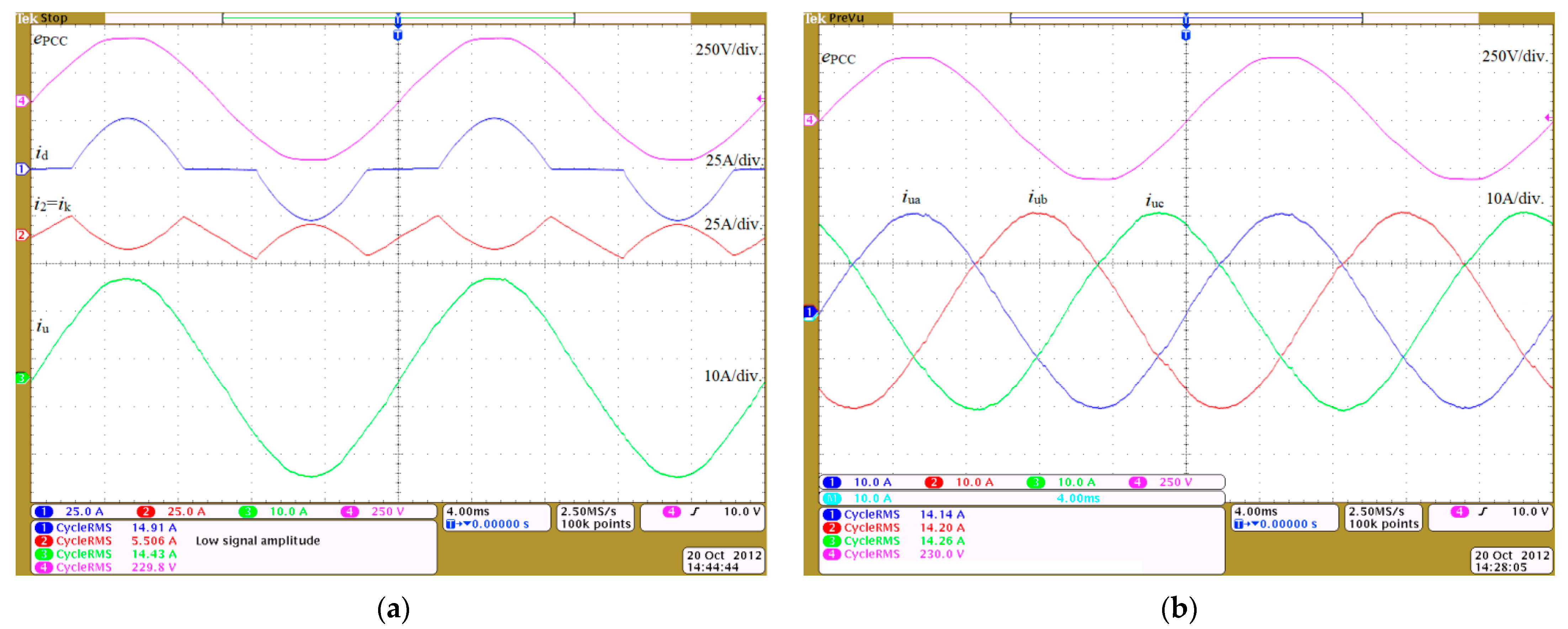
Figure 6 shows examples of waveforms obtained for the laboratory model. They illustrate the effectiveness of the predictive controller along with the current and voltage prediction algorithms. The presented laboratory system is a three-phase low-voltage power network (400 V, 50 Hz) and a non-linear load of apparent power equal to 10.3 kVA, in the form of a diode rectifier with an RC load on the DC side. A shunt active power filter with rated power equal to 10 kVA was connected between the supply network and the load via an LCL circuit with the following parameters: L1 = 2.0 mH, L2 = 1.4 mH, C = 10 µF.
The value of the THDi coefficient of the upstream current was equal to 44% with disabled compensation in the system. The results achieved when the APF was enabled show that the upstream current distortion was compensated to THDi = 2.5%, whilst the value of the THDu coefficient was compensated to 1.69%.
3. Stability Analysis
The subject of the stability analysis is the control system with the outer closed-loop current reference control, inner model-based predictive current controller and an object in the form of an LCL coupling circuit, an ideal grid voltage source and a current source-based load. The current controller requires both the information about state variables of the LCL circuit and the reference current signal for proper operation. Such a system is prone to the loss of stability in case of operating with an improper control sampling frequency and poor identification of the LCL circuit parameters required by the MPC controller. The presence of the outer control loop results in additional roots of the characteristic equation of the system. As the proposed control system is not designed to be adaptive, its important quality factor is the robustness. Due to the relatively high complexity of the system, certain simplifications were adopted for the need to perform this analysis. Performing the stability analysis demanded defining particular transfer functions of the system first and then determining their generalization. These operations as well as the stability analysis were performed with the utilization of MATLAB software with the following toolboxes: System Identification Toolbox, Control System Toolbox and Symbolic Math Toolbox.
3.1. Assumptions
The stability analysis was conducted with the presumption that the grid is ideally stiff, and thus operation under conditions of a weak grid is not considered in this paper. The discussed system is based on the discrete-continuous model, in which the applied predictive current controller is the discrete part, and the continuous parts are the voltage inverter and the LCL circuit. Therefore, the stability analysis of the entire system is possible only when it is reduced to either a continuous or a discrete form. However, reducing it to the discrete form allows the stability analysis as a function of the sampling frequency, which constitutes an essential parameter of the system as it affects the stability of the control system. On account of that, continuous parts were discretized and the whole system was examined in the z-domain. Furthermore, the model of the inverter was linearized and simplified. Assuming an unlimited uDC voltage and neglecting the inverter’s non-linearities, there is an opportunity to adopt a linear model of the inverter as a zero-order hold (ZOH).
3.2. Overall and Partial Transfer Functions
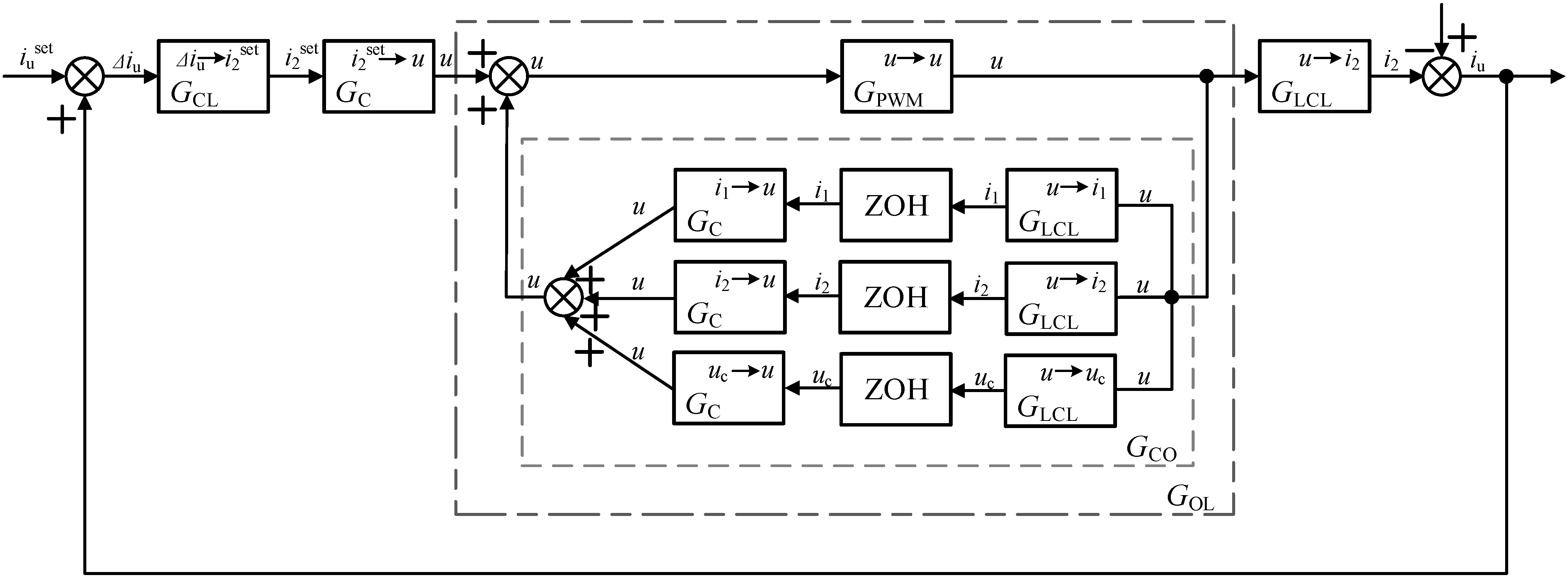
Figure 7 presents the z-domain block diagram of the proposed system with compensation for a particular harmonic current. This scheme contains all considered partial transfer functions, whilst equivalent block diagrams with generalized transfer functions are depicted in Figure 8. All symbols utilized both in diagrams and transfer functions are consistent with those used in the previous figures, tables and text.
The discrete transfer function matrix of the predictive model-based current controller derives from difference equations described in detail in [8] and is as follows:
where Ts denotes the sampling period.
The discrete transfer function matrix of the LCL circuit (analog part of the system) results from the cascade connection of the ZOH, which reflects the pulse operation of the APF inverter, and the LCL continuous transfer function matrix derived from differential equations of the LCL coupling circuit outlined in [8]. Therefore, the GLCL(z) matrix is described by the following equation:
where ωr is the LCL resonant angular frequency:
while the resonant frequency is expressed by
which in the discussed system is equal to fr = 2.25 kHz.
GCL(z) is the set current transfer function. Determining the reference current in the presented circuit requires transforming the signal into the frequency domain with the usage of the DFT. From a mathematical point of view, this operation is identical to the Park transform, where the angle of rotation is the product of the order of a given harmonic and the instantaneous angle of the grid voltage obtained from the phase-locked loop (PLL), followed by low-pass filtering. The next steps consist of PI control, prediction and the IDFT, which is the same as the inverse Park transform. Bearing this in mind, the GCL(z) matrix derives from the following equation:
where φ and k denote the instantaneous phase angle of the supply voltage fundamental harmonic and the order of the compensated harmonic current, respectively.
In the case where the matrices between the Park transforms are diagonal with the same coefficients on the main diagonal, the Park transform matrices do not affect the value of the resultant matrix. This is because the product of Park transform matrices is the identity matrix:
Therefore, the final transfer function can be expressed by
and is represented as follows:
where a is the coefficient of the low-pass filter, while Kp and Ki denote proportional and integral coefficients of the PI controller.
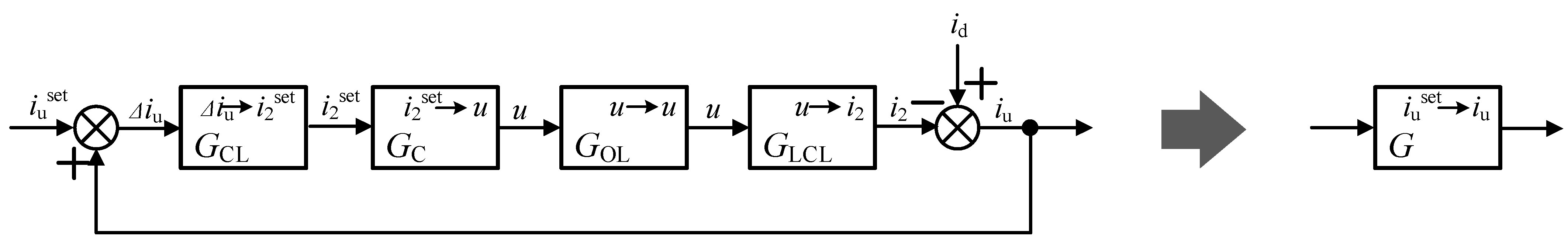
The whole system is reduced to the single-input, single-output (SISO) form, as it is shown in Figure 8. On account of that, the overall transfer function is represented as
with GOL(z) expressed by the following equation:
where the minus in the denominator results from taking into account the negative feedbacks in the transfer function of the current controller.
4. Results
The stability of the considered control system results from the root locations of the characteristic equation of the G(z) transfer function on the z-plane. In the discussed APF circuit, it is conditioned by the value of the sampling period, the Kp and Ki coefficients and the identification accuracy of the LCL coupling circuit parameters. The latter aspect is especially significant when the applied current controller is predictive. To examine the impact of this factor on stability, the exact parameters L1, L2 and C in the predictive controller transfer function GC(z) were replaced with the identified (measured or estimated) values L1c, L2c and Cc, respectively. This results from the fact that parameters of the LCL circuit implemented in the control algorithm (L1c, L2c, Cc) constitute the parameters of the current controller. Changes in their values, which determine the percentage accuracy of their compliance with the parameters of the LCL circuit, as well as the range of values of changes in the Ts, Kp and Ki parameters, define the area of stable operation of the system.
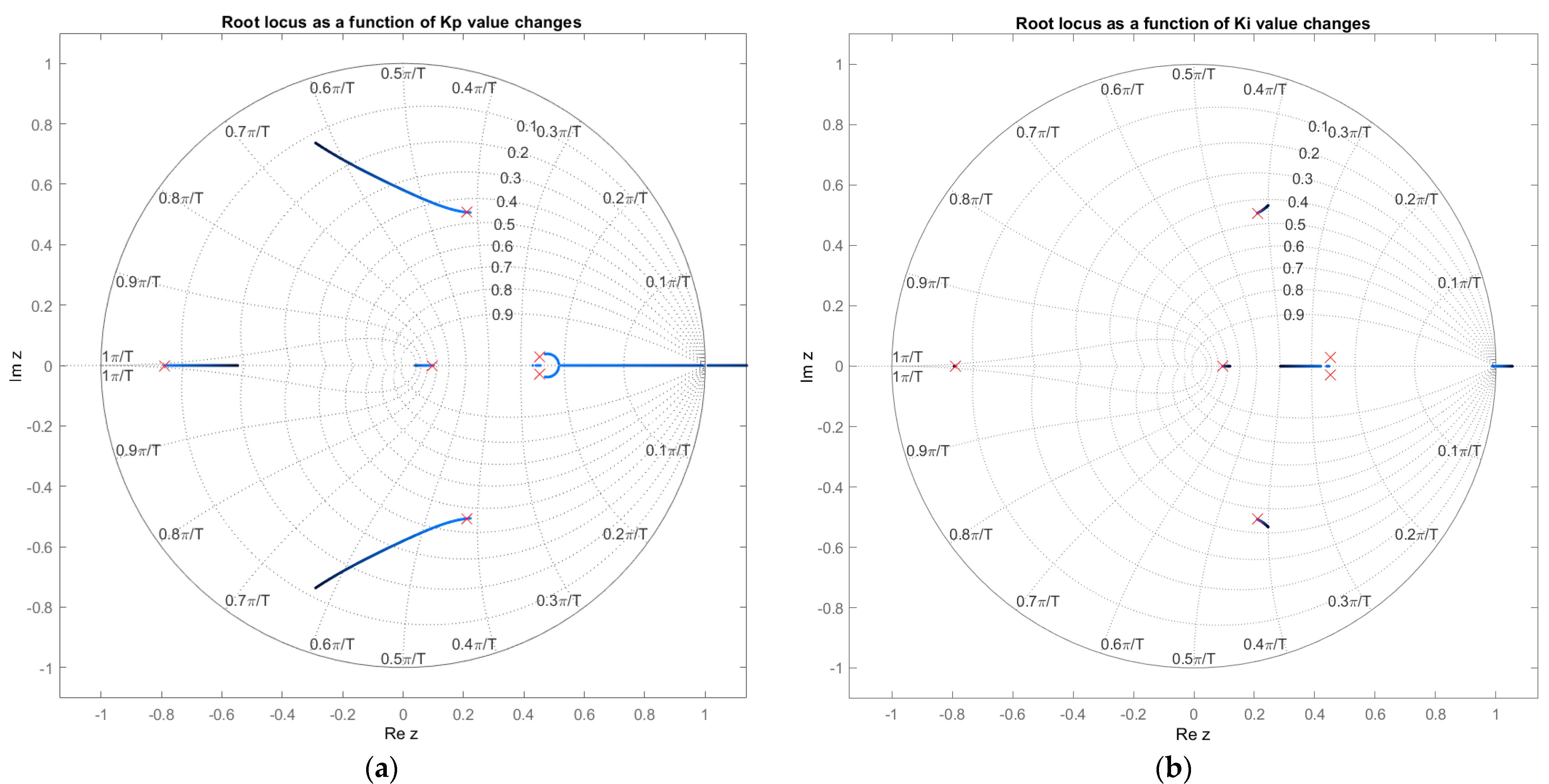
Root locus analyses of the APF feedback control system as a function of the above-mentioned parameters are presented in Figure 9. Red crosses in each figure indicate the pole locations of the discussed system for the following parameters: L1c = L1 = 150 µH, L2c = L2 = 75 µH, Cc = C = 100 µF, Ts = 6.25⸱10−5 s, Kp = 0.02, Ki = 10.0. The presented results were obtained from tests conducted in MATLAB software.
The spans of the permissible changes in the Kp and Ki coefficients in the area of system stability are below 1.08 and above 120, respectively, when the other parameter remains unchanged. This control system was not tested under the conditions of changes in both coefficients simultaneously.
The control system is stable in terms of the sampling period value being below 7.38⸱10−5 s and in the range from 1.35⸱10−4 s to 1.5⸱10−4 s. These values correspond to the sampling frequency between 6.67 and 7.46 kHz and above 13.55 kHz. The relation between the sampling frequency fs and the modulation frequency fPWM in the proposed system is as follows:
and thus the system remains stable when the modulator pulsation frequency is in the range from 3.33 to 3.73 kHz and above 6.77 kHz. This means that the minimum sampling frequency within the stable area is approximately 1.5 times the LCL circuit resonant frequency: fPWM = 1.5 fr. However, a relatively large margin of stability can be obtained when fPWM > 3 fr.
As far as the changes in the identification accuracy of the LCL coupling circuit parameters are concerned, the feedback control system remains stable for the given inductance value L1c in the range from 88% to 136% of the exact value (L1), for the inductance L2c above 64% of the exact value (L2) and for the capacitance Cc in the range from 74% to 290% of the exact value (C). Not only do these ranges far exceed the practical tolerances of the choke and capacitor parameters but they are also beyond the achievable accuracy of measurements of these quantities.
Simulation tests were conducted in PLECS to define the values of the considered parameters, for which the loss of stability is observed in the control system. The simulated control system is stable when the value of the L1c parameter is within the range from 89% to 136% of the exact value (L1), the value of L2c is above 64% of the exact value (L2) and the value of Cc is between 74% and 325% of the exact value (C). The loss of stability occurs when the sampling period is above 1.49⸱10−4 s and in the range from 1.29·10−4 to 7.38⸱10−5 s. The obtained values are almost completely consistent with the values achieved in the stability analysis conducted in MATLAB, which makes the results reliable.
Further tests performed for the determinants of the experimental system provided results which show that the stability regions for the examined parameters are wider than those obtained in the stability analysis. This is due to limits of the control signals which result from the value of the uDC voltage (and, consequently, the range of the inverter AC voltage) as well as the value of the APF’s maximum current. However, a relatively high consistency is obtained for the Ts parameter. It is an important issue on account of the fact that this parameter determines the value of the inverter modulation frequency fPWM, and in consequence, due to switching losses, the maximum rated power of the single-inverter-based APF. Although the system remains stable in a wide range of the mentioned parameter value changes, the compensation effectiveness beyond the stability region is noticeably lower, which is shown further in the paper. The comparison of the results obtained on the basis of the simulation tests, the stability analysis and tests performed for the determinants of the experimental system is presented in Table 2.
Presented results prove that the stability margins obtained by the analytical method ensure the stability in actual systems.
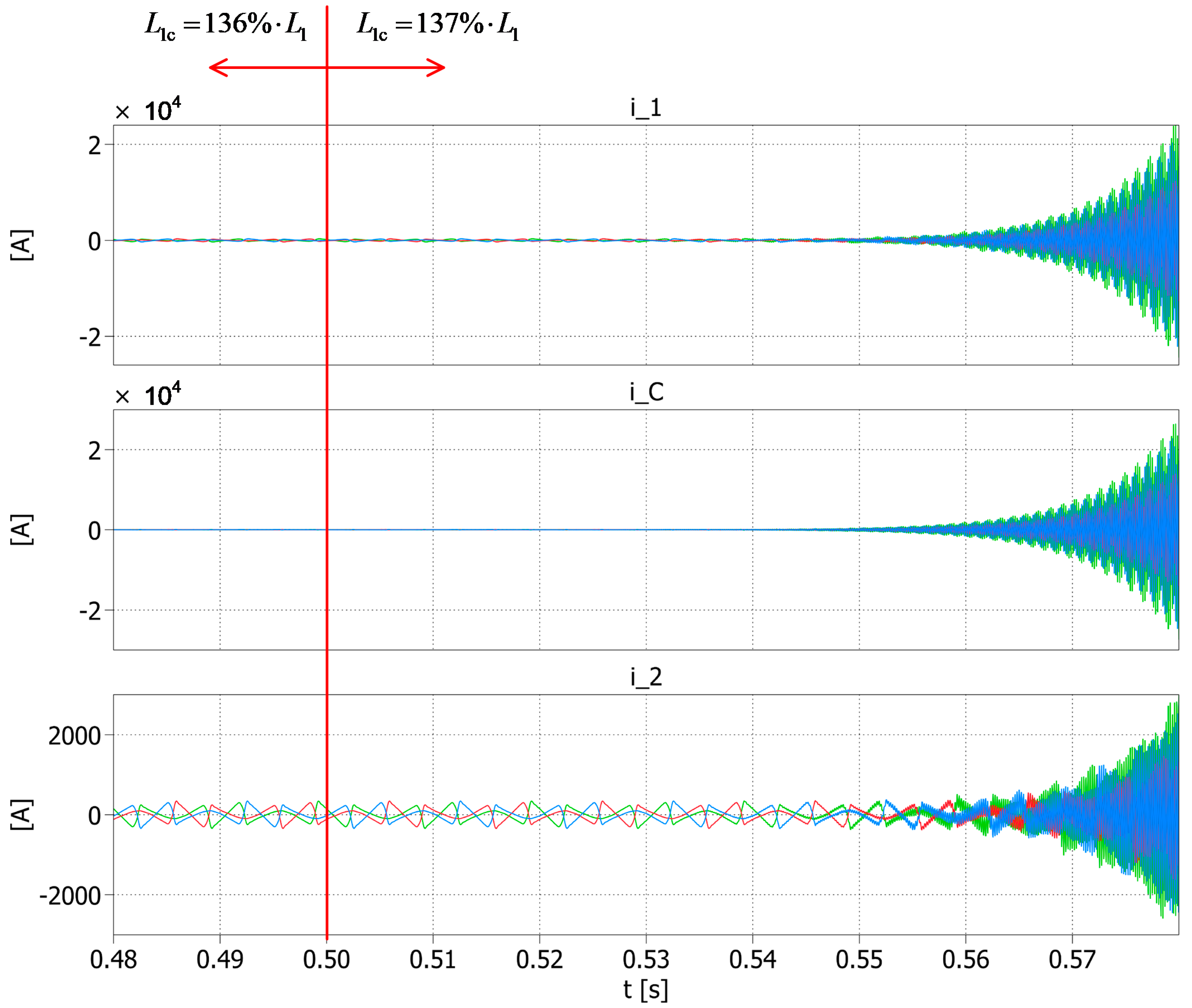
Sample waveforms of the APF current, measured on L1 and L2 inductances, illustrating the loss of stability are shown in Figure 10. The values of parameters L2c and Cc are equal to parameters L2 and C, respectively, given in Table 1. The value of parameter L1c is changed in the time equal to 0.5 s from the value L1c = 136% of L1 to the value L1c = 137% of L1, which is the same as exceeding the stability limit shown in Table 2. The waveforms up to time t = 0.5 s present stable operation of the system, whilst the waveforms in the time ranges from 0.5 to 0.6 s depict the system’s operation in case of loss of stability. The choice of the L1c parameter to represent the system stability loss results from the fact that the value of this parameter has the greatest impact on the system stability, which will be presented later in the paper.
The obtained results show that the greatest effects of the loss of stability in the control system are visible on the waveforms of currents i1 and iC as they reached very high values. The value of the current i2 is smaller due to the secondary influence of the resonance formed in the circuit L1-C.
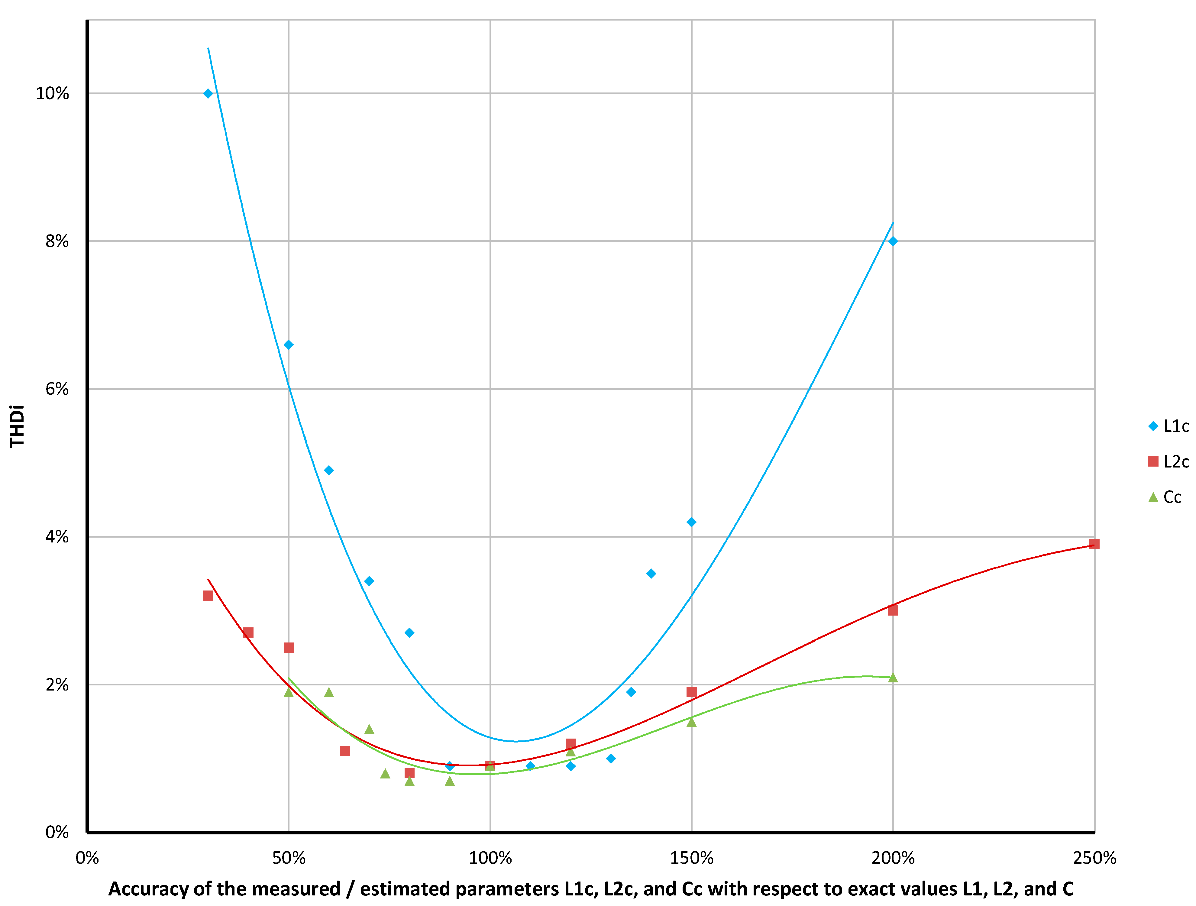
Figure 11 presents values of THDi in the PCC as a function of the LCL circuit parameter identification. It completes previous results and shows the effectiveness of compensation performed by the APF in case of introducing LCL parameters inaccurately in the control system. The presented characteristics are an approximation of the points obtained on the basis of a series of simulations, assuming that only one of the parameters is changed while the others are identified correctly and remain unchanged. The discussed parameters were tested within the following identification accuracy ranges: L1c: 30% ÷ 200% of L1, L2c: 30% ÷ 250% of L2, Cc: 50% ÷ 200% of C.
The obtained results show that the optimal values of the current controller parameters (L1c, L2c, Cc), from the point of view of the compensation effectiveness determined on the basis of the THD coefficient, are the exact values of the LCL circuit. It is also noticeable from the characteristics that the correctness of determining the value of inductance L1 has the greatest impact on the quality of compensation.
5. Conclusions
The obtained simulation results confirm a great level of grid harmonic currents compensation of an LCL-based shunt APF with predictive closed-loop control. Along with the high effective filtering performance, a simultaneous high reduction in filter current ripples associated with the pulse width modulation (PWM) modulation was achieved.
The presented stability analysis included the determination of overall and partial transfer functions of the discussed control system and defining the boundaries of particular parameter changes for which the control system remains stable. The APF stability region, obtained by the analytical method, is determined by the values of the parameters L1c, L2c, Cc, Kp, Ki and Ts in the following ranges: L1c = 88% ÷ 136% of L1, L2c > 64% of L2, Cc = 74% ÷ 290% of C, Kp < 1.08, Ki > 120, Ts < 7.38⸱10−5 s and Ts =1.35⸱10−4 ÷ 1.5⸱10−4 s, which correspond to the sampling frequency fs = 6.67 ÷ 7.46 kHz and fs > 13.55 kHz. The achieved results show that there is a wide range of the LCL circuit parameter identification accuracy for which the system is stable. This is very important in control systems with predictive current controllers. The stability range for the LCL circuit parameter value changes achieved by tests conducted for the determinants of the experimental system is even wider. From a practical point of view, this means that introducing the values of the parameters L1, L2 and C to the system on the basis of their rating plates, which are given with certain tolerances, ensures the system’s robustness to a sufficient degree. Furthermore, the obtained range of the switching frequency proves the possibility of the application of this APF in a system which requires a low switching frequency of the power transistors. Results acquired in the stability analysis performed in MATLAB were confirmed by simulation tests conducted in PLECS. Parameter values for which the control system lost its stability, obtained in both the stability analysis and simulation examinations, were consistent. Further analysis showed that the value of inductance L1 implemented in the control system (L1c) was the most influential regarding the effectiveness of compensation expressed by the value of the THDi coefficient. It was also noticed that the accuracy of LCL parameter identification affects the compensation quality realized by the APF. The greatest level of harmonic currents compensation was obtained for the values implemented in the current controller equal to the actual values of the coupling circuit.
Further research will focus on considering other factors influencing the stability of the system, such as the value of the grid impedance, as well as the type of load and its voltage susceptibility.
Author Contributions
Conceptualization, A.B. and D.W.; methodology, A.B. and D.W.; software, A.B. and D.W.; validation, A.B. and D.W.; formal analysis, A.B. and D.W.; investigation, A.B.; resources, A.B. and D.W.; data curation, A.B. and D.W.; writing—original draft preparation, A.B.; writing—review and editing, A.B and D.W.; visualization, A.B.; supervision, D.W. All authors have read and agreed to the published version of the manuscript.
Funding
This research received no external funding.
Institutional Review Board Statement
Not applicable.
Informed Consent Statement
Not applicable.
Data Availability Statement
The data presented in this study are available from the corresponding author on reasonable request.
Conflicts of Interest
The authors declare no conflict of interest.
References
- Sleszynski, W.; Cichowski, A.; Mysiak, P. Suppression of Supply Current Harmonics of 18-Pulse Diode Rectifier by Series Active Power Filter with LC Coupling. Energies 2020, 13, 6060. [Google Scholar] [CrossRef]
- Rao, M.U.M.; Rosalina, K.M. Transient stability improvement of Microgrid using Series Active Power Filters. In Proceedings of the 2019 Fifth International Conference on Electrical Energy Systems (ICEES), Chennai, India, 21–22 February 2019; pp. 1–4. [Google Scholar] [CrossRef]
- Sun, B.; Xie, Y.; Ma, H. An enhanced repetitive control strategy for shunt active power filter with LCL output filter. In Proceedings of the IECON 2015 41st Annual Conference of the IEEE Industrial Electronics Society, Yokohama, Japan, 9–12 November 2015; pp. 001351–001356. [Google Scholar] [CrossRef]
- Geng, H.; Zheng, Z.; Zou, T.; Chu, B.; Chandra, A. Fast Repetitive Control with Harmonic Correction Loops for Shunt Active Power Filter Applied in Weak Grid. IEEE Trans. Ind. Appl. 2019, 55, 3198–3206. [Google Scholar] [CrossRef]
- Mattavelli, P.; Marafao, F.P. Repetitive-based control for selective harmonic compensation in active power filters. IEEE Trans. Ind. Electron. 2004, 51, 1018–1024. [Google Scholar] [CrossRef]
- Chen, H.; Liu, H.; Xing, Y.; Hu, H.; Sun, K. Analysis and design of enhanced DFT-based controller for selective harmonic compensation in active power filters. In Proceedings of the 2018 IEEE Applied Power Electronics Conference and Exposition (APEC), San Antonio, TX, USA, 4–8 March 2018; pp. 1305–1309. [Google Scholar] [CrossRef]
- Chen, X.; Dai, K.; Xu, C.; Lin, X. Harmonic suppression and resonance damping for shunt APF with selective closed-loop regulation of PCC voltage. In Proceedings of the 2015 IEEE Energy Conversion Congress and Exposition (ECCE), Montreal, QC, USA, 20–24 September 2015; pp. 6439–6443. [Google Scholar] [CrossRef]
- Wojciechowski, D. Unified LCL circuit for modular active power filter. COMPEL Int. J. Comput. Math. Electr. Electron. Eng. 2012, 31, 1985–1997. [Google Scholar] [CrossRef]
- Tumbelaka, H.H.; Borle, L.J.; Nayar, C.V.; Lee, S.R. A grid current-controlling shunt active power filter. In Proceedings of the 2007 7th Internatonal Conference on Power Electronics, Daegu, South Korea, 22–26 October 2007; pp. 956–961. [Google Scholar] [CrossRef]
- Lascu, C.; Asiminoaei, L.; Boldea, I.; Blaabjerg, F. High Performance Current Controller for Selective Harmonic Compensation in Active Power Filters. IEEE Trans. Power Electron. 2007, 22, 1826–1835. [Google Scholar] [CrossRef]
- Mariethoz, S.; Rufer, A.C. Open loop and closed loop spectral frequency active filtering. IEEE Trans. Power Electron. 2002, 17, 564–573. [Google Scholar] [CrossRef]
- Mattavelli, P. A closed-loop selective harmonic compensation for active filters. IEEE Trans. Ind. Appl. 2001, 37, 81–89. [Google Scholar] [CrossRef] [Green Version]
- Chen, W.; Zhang, D.; Zhang, H.; Wang, Z.; Sun, M. The Research on Composite Control Strategy of Active Power Filter. In Proceedings of the 2019 34rd Youth Academic Annual Conference of Chinese Association of Automation (YAC), Jinzhou, China, 6–8 June 2019; pp. 431–436. [Google Scholar] [CrossRef]
- Gautam, S.; Aeidapu, M. Sine Cosine Algorithm Based Shunt Active Power Filter For Harmonic Compensation. In Proceedings of the 2019 3rd International Conference on Electronics, Communication and Aerospace Technology (ICECA), Coimbatore, India, 12–14 June 2019; pp. 1051–1056. [Google Scholar] [CrossRef]
- Ouchen, S.; Steinhart, H.; Blaabjerg, F.; Benbouzid, M.; Betka, A.; Gaubert, J.P. Performance Analysis of Direct Power Control with Space Vector Modulation for Shunt Active Power Filter. In Proceedings of the IECON 2019 45th Annual Conference of the IEEE Industrial Electronics Society, Lisbon, Portugal, 14–17 October 2019; pp. 467–472. [Google Scholar] [CrossRef]
- Yang, L.; Yang, J. Robust Current Control Method for LCL-Type Shunt Active Power Filters with Inverter-Side Current Feedback Active Damping. In Proceedings of the 2018 IEEE Energy Conversion Congress and Exposition (ECCE), Portland, OR, USA, 23–27 September 2018; pp. 5706–5712. [Google Scholar] [CrossRef]
- Cao, X.; Dong, K.; Wei, X. An Improved Control Method Based on Source Current Sampled for Shunt Active Power Filters. Energies 2020, 13, 1405. [Google Scholar] [CrossRef] [Green Version]
- Wang, S.; Pei, Y.; Yi, H.; Zhang, J.L. A New High Control Precision Active Power Filter. In Proceedings of the 2019 IEEE 10th International Symposium on Power Electronics for Distributed Generation Systems (PEDG), Xian, China, 3–6 June 2019; pp. 1109–1112. [Google Scholar] [CrossRef]
- Mysak, T.V.; Shapoval, I.A. A simple control strategy for a three-phase shunt active power filter based on second-order sliding mode. In Proceedings of the 2020 IEEE 4th International Conference on Intelligent Energy and Power Systems (IEPS), Istanbul, Turkey, 7–11 September 2020; pp. 27–32. [Google Scholar] [CrossRef]
- Iturra, R.G.; Cruse, M.; Mütze, K.; Dresel, C.; Soleimani, I.; Thiemann, P. Model Predictive Control for Shunt Active Power Filter with Harmonic Power Recycling Capability. In Proceedings of the 2018 International Conference on Smart Energy Systems and Technologies (SEST), Sevilla, Spain, 10–12 September 2018; pp. 1–6. [Google Scholar] [CrossRef]
- Yi, H.; Zhuo, F.; Wang, X.; Liu, J. Study of closed-loop control scheme for source current detection type Active Power Filter. In Proceedings of the 2010 IEEE Energy Conversion Congress and Exposition, Atlanta, GA, USA, 12–16 September 2010; pp. 145–150. [Google Scholar] [CrossRef]
- Briz, F.; Díaz-Reigosa, D.; Degner, M.W.; García, P.; Guerrero, J.M. Dynamic behavior of current controllers for selective harmonic compensation in three-phase active power filters. In Proceedings of the 2011 IEEE Energy Conversion Congress and Exposition, Phoenix, AZ, USA, 17–22 September 2011; pp. 2892–2899. [Google Scholar] [CrossRef] [Green Version]
- Yang, L.; Yang, J.; Gao, M.; Watson, A.; Wheeler, P. Current Control of LCL-Type Shunt APFs: Damping Characteristics, Stability Analysis, and Robust Design Against Grid Impedance Variation. IEEE J. Emerg. Sel. Top. Power Electron. 2020. [Google Scholar] [CrossRef]
- Zhang, Y.; Dai, K.; Chen, X.; Kang, Y.; Dai, Z. Stability Analysis of SAPF by Viewing DFT as Cluster of BPF for Selective Harmonic Suppression and Resonance Damping. IEEE Trans. Ind. Appl. 2019, 55, 1598–1607. [Google Scholar] [CrossRef]
- Hoon, Y.; Mohd Radzi, M.A.; Hassan, M.K.; Mailah, N.F. DC-Link Capacitor Voltage Regulation for Three-Phase Three-Level Inverter-Based Shunt Active Power Filter with Inverted Error Deviation Control. Energies 2016, 9, 533. [Google Scholar] [CrossRef] [Green Version]
- Bing, Y.; Jiang, D.; Liang, Y.; Jiang, C.; He, T.; Yang, L.; Hu, P. Modified Modeling and System Stabilization of Shunt Active Power Filter Compensating Loads with μF Capacitance. Energies 2019, 12, 2084. [Google Scholar] [CrossRef] [Green Version]
- Popescu, M.; Bitoleanu, A.; Suru, C.V.; Linca, M.; Subtirelu, G.E. Adaptive Control of DC Voltage in Three-Phase Three-Wire Shunt Active Power Filters Systems. Energies 2020, 13, 3147. [Google Scholar] [CrossRef]
- Grugel, P. Stability analysis of Parallel Active Power Filter operating on the basis of network voltage distortion. In Proceedings of the 2016 10th International Conference on Compatibility, Power Electronics and Power Engineering (CPE-POWERENG), Bydgoszcz, Poland, 29 June–1 July 2016; pp. 240–243. [Google Scholar] [CrossRef]
- Guzman Iturra, R.; Thiemann, P. Asymmetrical Three-Level Inverter SiC-Based Topology for High Performance Shunt Active Power Filter. Energies 2020, 13, 141. [Google Scholar] [CrossRef] [Green Version]
- Imam, A.A.; Sreerama Kumar, R.; Al-Turki, Y.A. Modeling and Simulation of a PI Controlled Shunt Active Power Filter for Power Quality Enhancement Based on P-Q Theory. Electronics 2020, 9, 637. [Google Scholar] [CrossRef]
- Wang, L.; Lam, C.; Wong, M. The Analysis of DC-link Voltage, Compensation Range, Cost, Reliability and Power Loss for Shunt (Hybrid) Active Power Filters. In Proceedings of the 2018 IEEE PES Asia-Pacific Power and Energy Engineering Conference (APPEEC), Kota Kinabalu, MA, USA, 7–10 October 2018; pp. 640–645. [Google Scholar] [CrossRef]
- Torabi Jafrodi, S.; Ghanbari, M.; Mahmoudian, M.; Najafi, A.M.G.; Rodrigues, E.; Pouresmaeil, E. A Novel Control Strategy to Active Power Filter with Load Voltage Support Considering Current Harmonic Compensation. Appl. Sci. 2020, 10, 1664. [Google Scholar] [CrossRef] [Green Version]
- Gao, N.; Lin, X.; Wu, W.; Blaabjerg, F. Grid Current Feedback Active Damping Control Based on Disturbance Observer for Battery Energy Storage Power Conversion System with LCL Filter. Energies 2021, 14, 1482. [Google Scholar] [CrossRef]
Figure 1.
Main circuit structure.
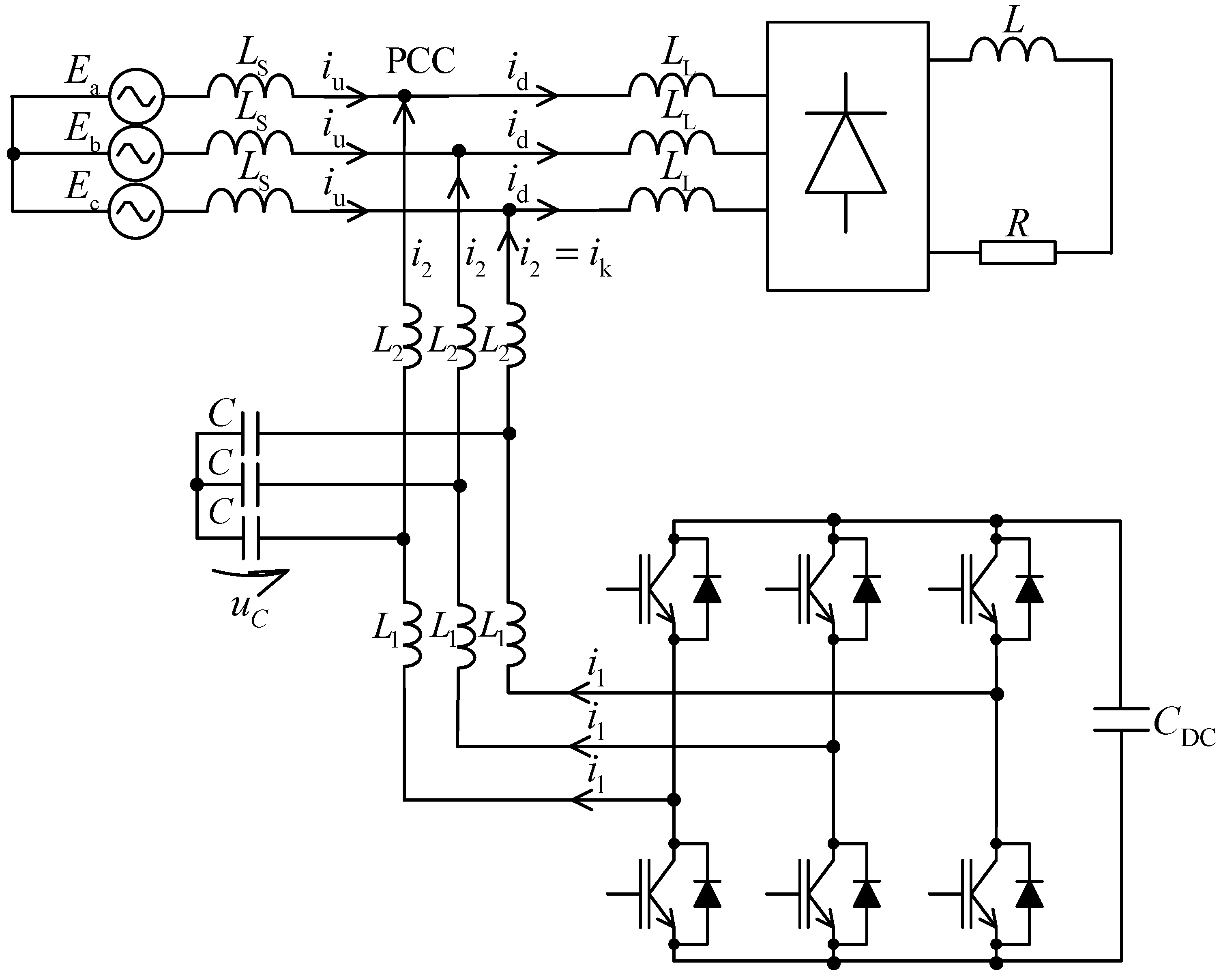
Figure 2.
Block diagram of the control system.
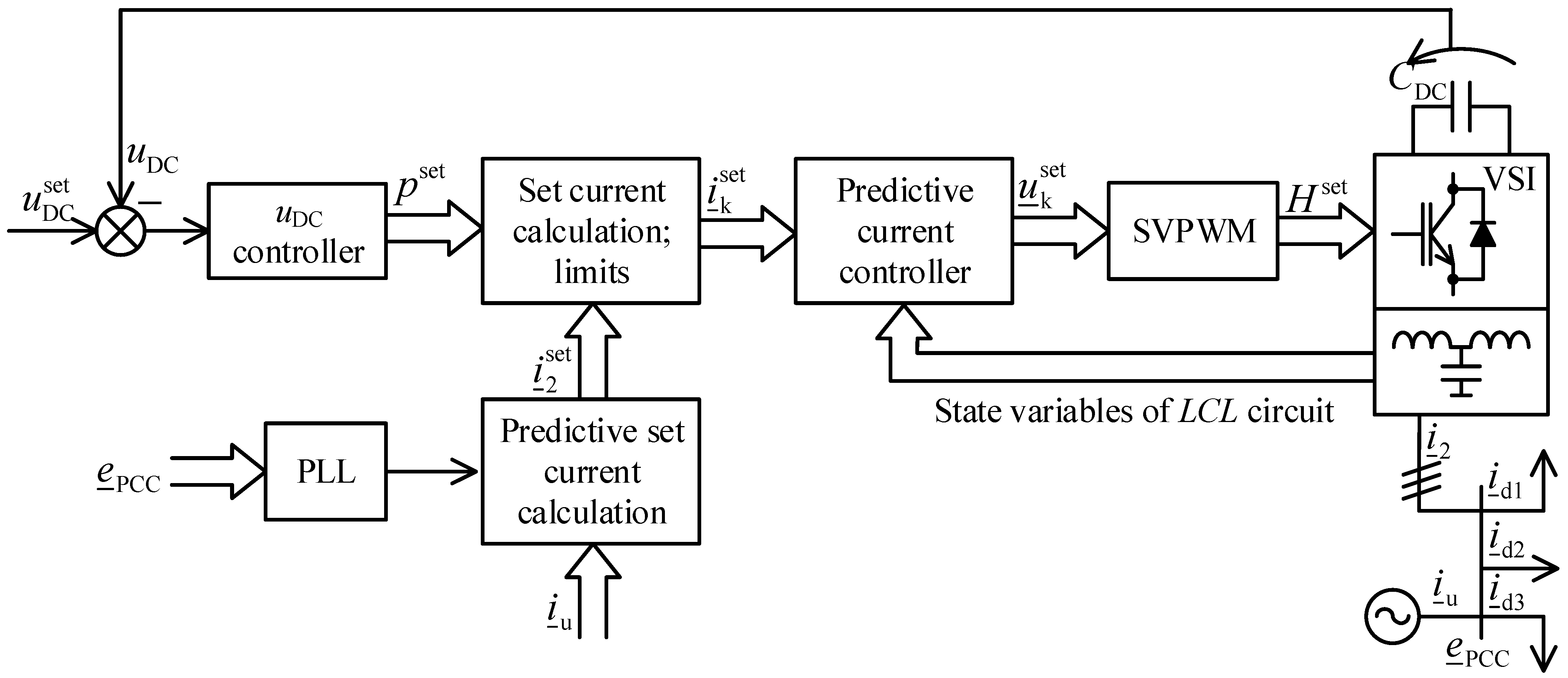
Figure 3.
Block diagram of the determination of the particular current harmonic to be compensated.

Figure 4.
Harmonic compensation disabled: (a) voltage waveform in the PCC; THDu = 5.11%; (b) upstream current waveform in the PCC; THDi = 23.42%.
Figure 4.
Harmonic compensation disabled: (a) voltage waveform in the PCC; THDu = 5.11%; (b) upstream current waveform in the PCC; THDi = 23.42%.
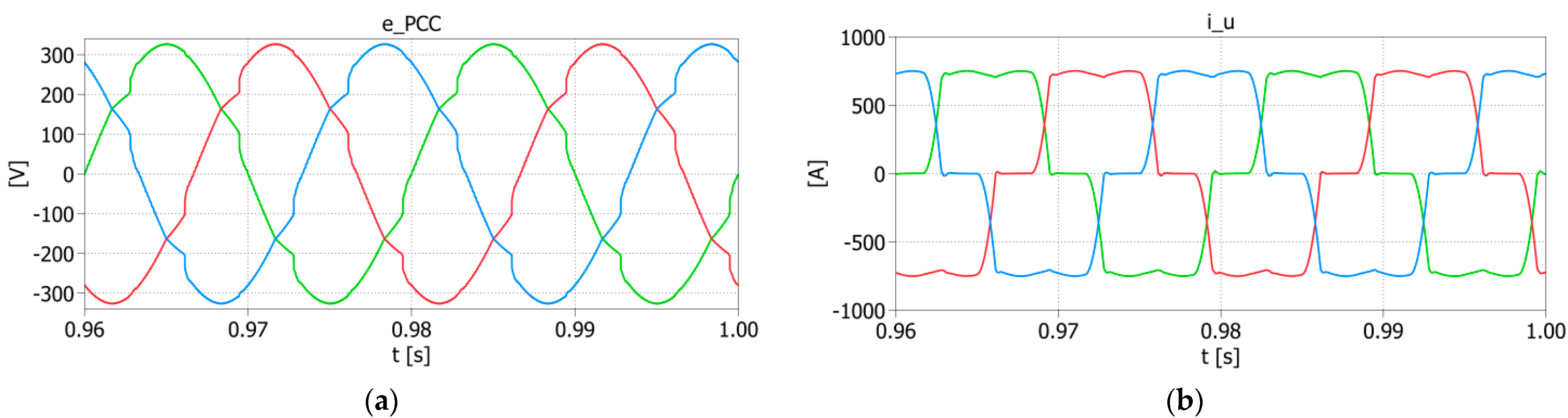
Figure 5.
Harmonic compensation enabled: (a) voltage waveform in the PCC; THDu = 1.17%; (b) upstream current waveform in the PCC; THDi = 0.87%; (c) L1 current waveform (i1); (d) L2 current waveform (i2 = ik).
Figure 5.
Harmonic compensation enabled: (a) voltage waveform in the PCC; THDu = 1.17%; (b) upstream current waveform in the PCC; THDi = 0.87%; (c) L1 current waveform (i1); (d) L2 current waveform (i2 = ik).


Figure 6.
Oscillograms of the following waveforms: (a) from the top: voltage in the PCC, downstream current, APF current, upstream current in the PCC; (b) from the top: voltage in the PCC, three phases of the upstream current in the PCC.
Figure 6.
Oscillograms of the following waveforms: (a) from the top: voltage in the PCC, downstream current, APF current, upstream current in the PCC; (b) from the top: voltage in the PCC, three phases of the upstream current in the PCC.

Figure 7.
Z-domain control block diagram.

Figure 8.
Z-domain equivalent control block diagrams.

Figure 9.
Results of the APF closed-loop control system stability analysis. Root locus as a function of the following parameter value changes: Kp (a), Ki (b), Ts (c), L1c (d), L2c (e), Cc (f).
Figure 9.
Results of the APF closed-loop control system stability analysis. Root locus as a function of the following parameter value changes: Kp (a), Ki (b), Ts (c), L1c (d), L2c (e), Cc (f).

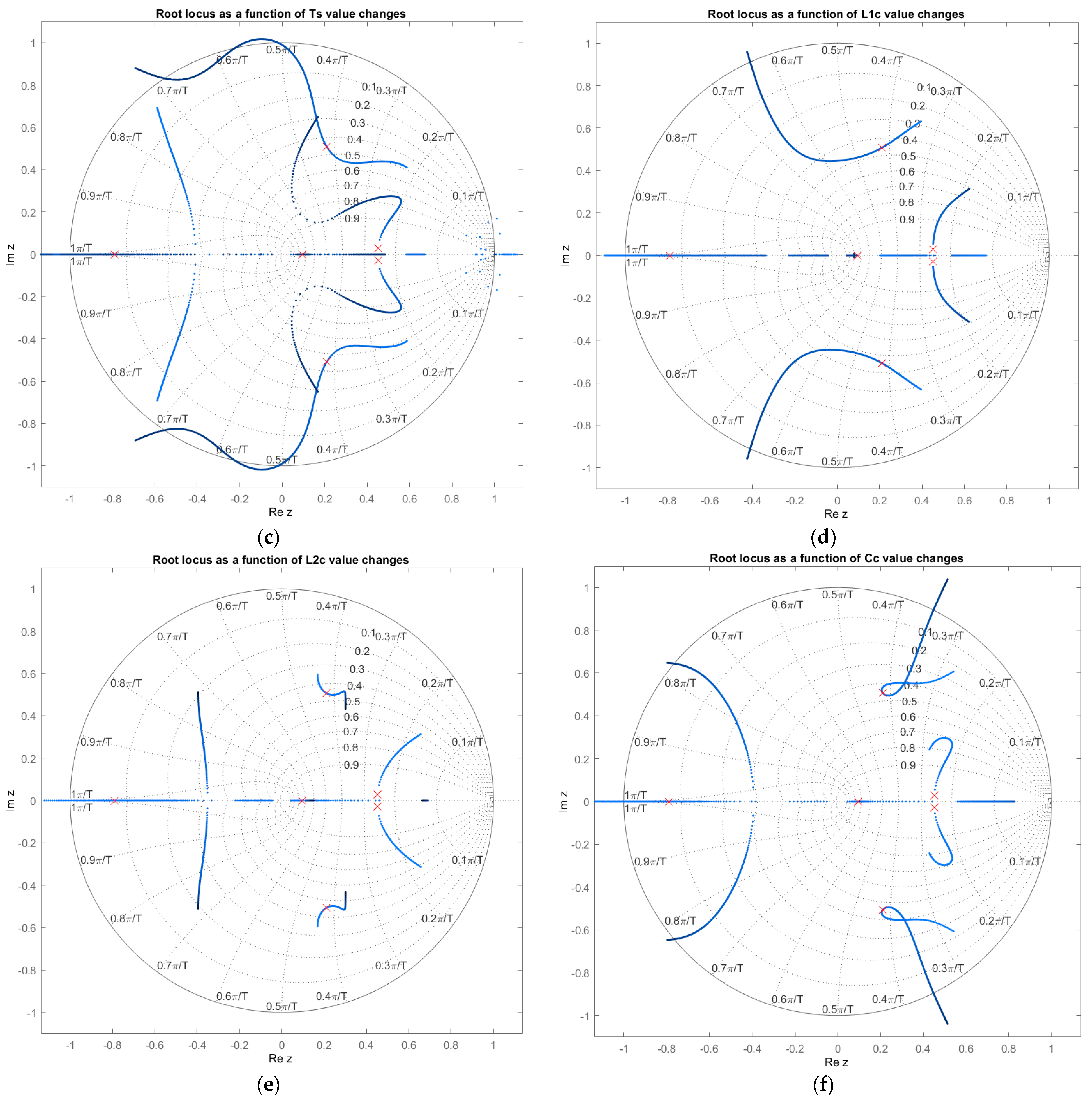
Figure 10.
Loss of stability in the control system after changing the value of L1c parameter when t = 0.5 s. From the top: L1 current waveform (i1), C current waveform (iC), L2 current waveform (i2 = ik).
Figure 10.
Loss of stability in the control system after changing the value of L1c parameter when t = 0.5 s. From the top: L1 current waveform (i1), C current waveform (iC), L2 current waveform (i2 = ik).

Figure 11.
THDi value changes as a function of the accuracy of LCL circuit parameter identification.
Figure 11.
THDi value changes as a function of the accuracy of LCL circuit parameter identification.


Table 1.
Parameters of proposed system.
| Parameter | Value |
|---|---|
| Line to line grid voltage | 3 × 400 V |
| Grid frequency | f = 50 Hz |
| Grid inductance | LS = 40 µH |
| Non-linear load | 6-pulse diode bridge with RL load (R = 0.7 Ω, L = 1.0 mH) |
| Non-linear load inductor | LL = 40 µH |
| LCL circuit | L1 = 150 µH, L2 = 75 µH, C = 100 µF |
| APF rated power | 120 kVA |
| Deadtime (uncompensated) | 3.0 µs |
| IGBT voltage drop (uncompensated) | 1.5 V |
| Diode voltage drop (uncompensated) | 1.0 V |
| PWM carrier frequency | fPWM = 8 kHz |
| Sampling frequency | fs = 16 kHz |
Table 2.
Comparison of analytical and simulation stability limits of the system.
| L1c Parameter | L2c Parameter | Cc Parameter | Ts Parameter | |
|---|---|---|---|---|
| Stability analysis performed in MATLAB | 88% ÷ 136% of L1 | >64% of L2 | 74% ÷ 290% of C | 150 ÷ 135 µs and <73.8 µs |
| Simulation tests conducted in PLECS | 89% ÷ 136% of L1 | >64% of L2 | 74% ÷ 325% of C | 149 ÷ 130 µs and <73.8 µs |
| Tests performed for the determinants of the experimental system | 13% ÷ 214% of L1 | >16% of L2 | 24% ÷ 315% of C | <150 µs |
Publisher’s Note: MDPI stays neutral with regard to jurisdictional claims in published maps and institutional affiliations. |
© 2021 by the authors. Licensee MDPI, Basel, Switzerland. This article is an open access article distributed under the terms and conditions of the Creative Commons Attribution (CC BY) license (https://creativecommons.org/licenses/by/4.0/).
Share and Cite
MDPI and ACS Style
Bielecka, A.; Wojciechowski, D. Stability Analysis of Shunt Active Power Filter with Predictive Closed-Loop Control of Supply Current. Energies 2021, 14, 2208. https://doi.org/10.3390/en14082208
AMA Style
Bielecka A, Wojciechowski D. Stability Analysis of Shunt Active Power Filter with Predictive Closed-Loop Control of Supply Current. Energies. 2021; 14(8):2208. https://doi.org/10.3390/en14082208
Chicago/Turabian StyleBielecka, Agata, and Daniel Wojciechowski. 2021. "Stability Analysis of Shunt Active Power Filter with Predictive Closed-Loop Control of Supply Current" Energies 14, no. 8: 2208. https://doi.org/10.3390/en14082208
Note that from the first issue of 2016, this journal uses article numbers instead of page numbers. See further details here.