1. Introduction
The development of AC drive systems has led to an increase in application of high-power equipment. A multiphase motor drive system has lower torque ripple and higher fault tolerance for open circuit short circuit or other faults, making it suitable for high-precision and high-reliability scenarios [
1,
2,
3]. Research on multiphase motors aims at improving the reliability, fault diagnosis, and fault-tolerant operation of specific targets. Keeping these applications in mind, several recent works have focused on the development of high-performance, fault-tolerant control schemes for induction machines (IMs) and permanent magnet synchronous machines (PMSMs) [
4,
5,
6,
7]. The diagnoses focus on rapidity and accuracy [
8,
9], and adoption of effective isolation measures, such that a corresponding fault-tolerant control scheme can be adopted. The important goal of a fault-tolerant control strategy is to be able to maintain the normal index operation effectively and stably after fault isolation. This could help minimize the fault-tolerant torque ripple and interference of fault-tolerant switching on the system.
Based on the principle of constant magnetomotive force (MMF), the hysteresis loop method is used to realize single-phase fault tolerance with the optimization objective of minimum copper loss (MCL) and maximum torque output (MTO) [
10]. Based on reconfiguring maximum round MMF, an open-circuit fault-tolerant control method for FPMSM is proposed in [
11]. In papers [
12,
13], the transformation matrix of the normal five-phase permanent magnet synchronous motor is reduced to achieve a single-phase fault-tolerant algorithm. In [
14], the single-phase open dimension-reduction mathematical model is established. In order to solve the problem of space decoupling during failure, an additional transformation matrix is added to transform it into a stationary equation, which includes disturbance. At the same time, feed forward control is used to compensate for the disturbance, and single-phase open current fault tolerance is achieved. Besides, model prediction and current prediction are also applied in dimension reduction single-phase fault tolerance control in [
15]. This is because dimensional reduction transformation of the transformation matrix is required to achieve dimensional reduction fault-tolerance control, and different mathematical models and different order transformation matrix need to be established for single-phase, adjacent two-phases, and non-adjacent two-phase open-fault. Therefore, the diversity of transformation matrix and mathematical model result in a great increase of the complexity of fault tolerance. In [
16], the fault-tolerant control of normal decoupling transformation is applied in a fault-tolerant state, and theoretical analysis proves that this strategy can guarantee that the magnetomotive force remains unchanged before and after fault tolerance, and it is verified on a seven-phase induction motor. In [
17,
18], fault tolerant control of normal decoupling is realized on a 15-phase induction motor and double-three-phase permanent magnet synchronous motor. The latter further analyzes the influence of three-harmonic magnetomotive force on the torque ripple of the double-three-phase permanent magnet synchronous motor, but does not provide a compensation scheme for the torque ripple. In order to optimize the torque ripple of fault tolerance, the papers [
19,
20] adopt the method of harmonic current injection to effectively suppress the torque ripple of fault-tolerant motors and improve fault-tolerant performance.
Voltage, torque, and magnetic chain are not affected when the original decoupling matrix remains unchanged under open-fault. This paper proposes a unified fault-tolerant control strategy with torque ripple compensation. Compared with other existed fault-tolerant algorithms, the proposed control strategy avoids different transformation matrices of different open-faults. It is easier to switch between each fault-tolerant and normal operation. This strategy is also applicable to various open-phase faults, and the method of unified torque compensation (TC) can effectively suppress torque ripple under all open-phase fault-tolerant conditions. As with other methods, the proposed unified TC method relies on accurate motor parameters. In this paper, the fault-tolerant current relationship in single-phase, adjacent, and non-adjacent two-phase open-circuit models are analyzed. Under one-phase open fault, the strategy realizes two kinds of fault operation modes using the principle of single-phase maximum torque output (MTO) and minimum copper loss (MCL) of stator by only changing the harmonic spatial reference current. By analyzing the torque ripple of the unified fault-tolerant control strategy in the normal decoupling space, a unified torque compensation method is proposed to suppress the torque ripple in all open-phase conditions. The decoupling relationship of fault-tolerant current was verified by Simulink. The torque ripple of fault-tolerant and effect of torque compensation (TC) under various fault-tolerant states are simulated by finite element simulation. Finally, the fault-tolerant experiments under various fault-tolerant states, including single-phase, adjacent two-phase, and non-adjacent two-phase verify the correctness of the unified fault-tolerant method and the stability of switching between normal operation modes and various fault-tolerant operation modes. Finally, the correctness of the proposed torque compensation (TC) method is verified in an AC open-fault experiment.
2. Mathematical Model of Sinusoidal FPMSM
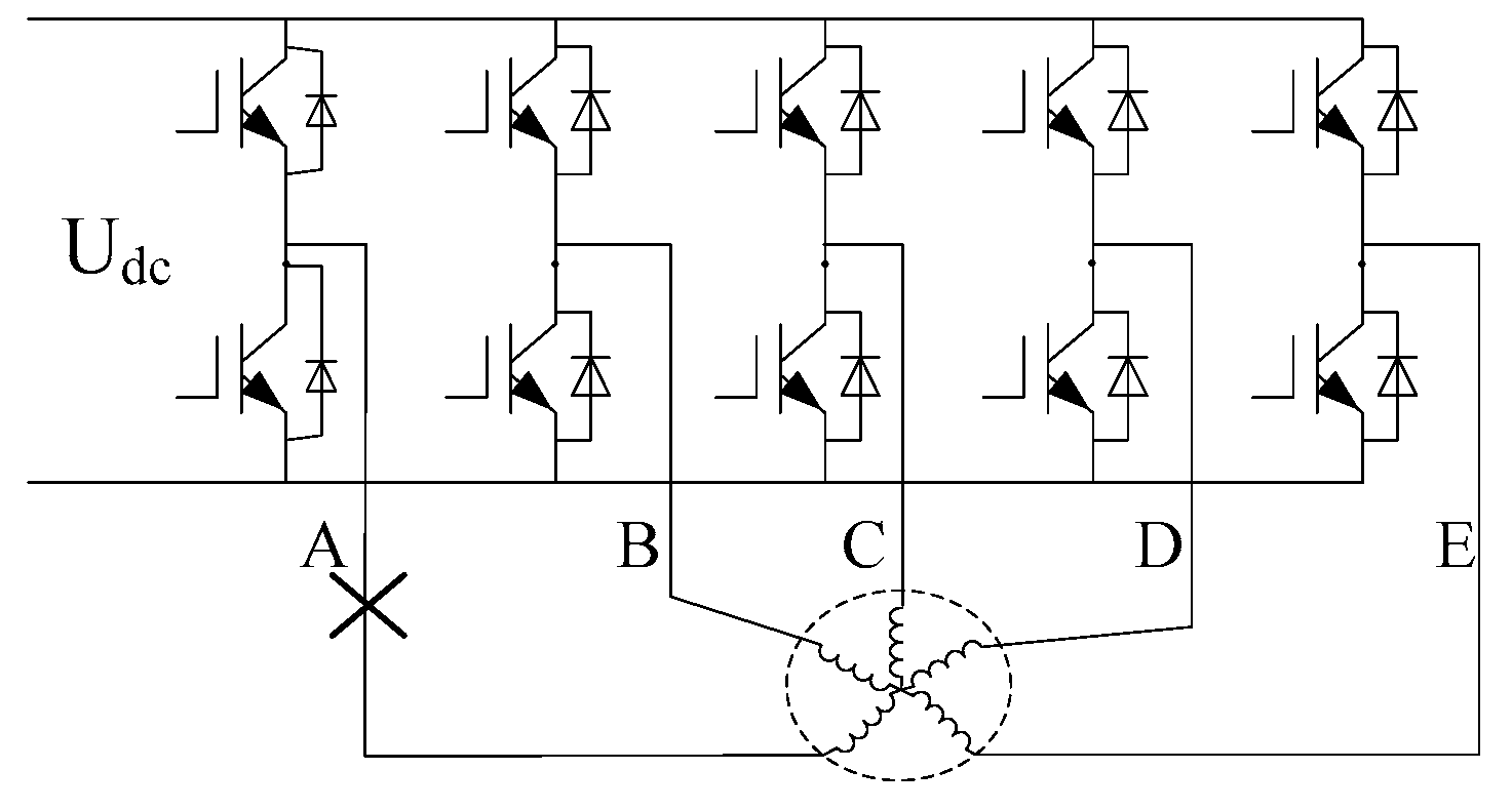
The topology of the main circuit of the FPMSM drive system, powered by a normal five-phase voltage source inverter, is shown in
Figure 1.
Figure 1 shows the block diagram of the drive system of the five-phase permanent magnet synchronous motor. In the sinusoidal five-phase permanent magnet synchronous motor, the effects of core magnetic saturation, hysteresis, eddy current, and motor leakage inductance are ignored. The decoupling algorithm based on field-oriented control (FOC) can map the variables of a five-phase motor to two orthogonal spatial planes. The fundamental wavelet sub-plane is involved in the electromechanical energy conversion, while the harmonic subspace is not. The normally decoupled Clark transformation matrix is:
In the equation, X represents voltage (
U), current (
I), flux (
) and other variables.
The research object in this paper is sinusoidal five-phase PMSM, in which the third-harmonic subspace does not participate in the electromechanical energy conversion. Therefore, in order to facilitate fault tolerance research, rotation coordinate Park transform is only done for the fundamental sub-plane. The transformation matrix is:
The voltage equation of the five phase permanent magnet synchronous motor is:
The flux linkage equation is:
where
p is the differential coefficient;
RS,
LS are stator resistance and inductance matrix.
The torque equation of FPMSM is [
21]:
where
are the amplitude of first and third magnet flux;
Ld,
Ld3 are the first and third inductance of d axis;
Lq,
Lq3 are the first and third inductance of q axis.
L13 is the cross mutual inductance of two subspaces; and P
n is the polar logarithm.
The back electromotive force of sinusoidal FPMSM is close to a sinusoid and no energy conversion in third harmonic subspace. The torque equation is [
22]:
3. Single-Phase Fault-tolerant Algorithm Based on Normal Decoupling
In the case of the open-circuit fault tolerance of five-phase star connected sinusoidal PMSM, the current of the fault phase is zero—the other normal phase satisfies the constraint that the sum of the current is zero. The five-phase PMSM with a single-phase open is shown in
Figure 2.
Assume that the five-phase PMSM has an open A phase, the windings are not damaged, and not affected by other physics factors. Under the condition that the decoupling transform matrix is not changed, it is important to ensure that except for the current, the voltage, flux and torque equations of the motor are not affected. Due to the lack of A phase current degree of freedom (
iA = 0), the first column of the second row and the fourth row of the normal decoupled transformation matrix (2) are all zero. It can be seen that
iβ and
iβ3 are not correlated to the A phase current, so they are not affected by the A phase open circuit. The other
iα,
iα3 and
iz are affected by the open circuit, and satisfy the constraint formula:
According to Equation (8), under the A phase open circuit condition, there is always a constraint Equation (9) through normal decoupling transformation:
There is a linear relationship between the harmonic plane α axis and the fundamental wave plane α axis; and the fundamental wave plane and harmonic plane current is no longer decoupled. If the harmonic current is forced to be set to zero under normal decoupling conditions, the current component of the fundamental wave plane will be affected, and torque ripple will inevitably be generated. The fundamental current component participates in the electromechanical energy conversion, which completes the fault-tolerant operation of the motor under the principle of keeping the fundamental magnetic potential unchanged. It can be seen that the fault-tolerant operation target under a normal decoupling condition is consistent with that under a normal condition, that is, to keep the fundamental current unchanged. The harmonic current component depends on the fault-tolerance optimal target. In order to ensure the control degrees of freedom of the fundamental wave (torque output) plane without DC bias, the harmonic plane current can be set in the form of Equation (10):
For single-phase fault-tolerance, this paper optimizes the total copper loss of the motor ontology and the output capacity of the inverter. The optimization targets are minimum copper loss and maximum torque output, respectively.
3.1. Principle of Minimum Copper Loss(MCL)
The principle of minimum copper loss is to reduce the total copper loss of current as much as possible under the condition of constant torque output, which can improve the thermal environment of the motor and realize the maximum torque current ratio control under fault tolerance. The total copper loss of the normally decoupled motor is as follow:
Because the current variables in the stationary coordinate system are sinusoidal components, it is necessary to transform (8), (9) and the first two lines of (3) into the d-q coordinate system, and bring in Equation (11), while making
id = 0. The expression of copper loss is as follows:
In order to guarantee torque stability in open-phase condition,
iq will produce a fixed copper loss under the
id = 0 control strategy. Therefore, the minimum copper loss factor is the harmonic subspace β axis current. When
iβ3 = 0, the minimum copper loss is achieved. The control law of minimum copper loss is:
As shown in Equation (14), the current in (13) is transformed from the inverse transformation of the normal coordinate system to the natural coordinate system of the five phases. In the formula, Im is the current amplitude of the five phase PMSM in normal operation.
3.2. Principle of Maximum Torque Output(MTO)
It can be seen from Equation (14) that the current amplitude of non-fault phase obtained under the principle of minimum copper loss is unequal. Although the minimum copper loss can be guaranteed, because the amplitude of B and C phase currents is larger, it is easy to be limited by the bus voltage of the inverter, so the maximum output torque of the inverter cannot be achieved. Therefore, the maximum output capacity of the inverter can be guaranteed under the constraint of equal amplitude of four-phase non-fault current. This principle is also known as the principle of amplitude equivalence. Then, transform (10) and
id,
iq by inverse transformation of normal decoupling. The parameter obtained is shown in (15):
Therefore, the control law of maximum torque output is:
When the parameter is substituted into the four-phase current amplitude formula, the five-phase fault-tolerant current in a natural coordinate system should satisfy Equation (17).
4. Double Phase Fault-tolerant Algorithm Based on Normal Decoupling
As shown in
Figure 3, the two-phase open circuit conditions of the five-phase PMSM can be considered as two cases. One is adjacent two-phase fault (AB), the other is the non-adjacent two-phases fault (AC). When
iq is constant in the normal decoupled state, in both cases, the two-phase fault-tolerant control can be accomplished under the premise that the magnetic potential is consistent with the normal state. Thus, a relatively stable running state can be guaranteed.
The constraint condition of two-phase open circuit conditions in the current of two phases is zero, by which the current control law of harmonic wave subspace can be solved directly.
4.1. Adjacent Two-phase (AB) Fault-tolerant Control
Consistent with the solution of single-phase fault, the five-phase current can be obtained by inverse transformation of the stationary coordinates in the case of two-phase fault. According to
iA = 0,
iB = 0, (18) is obtained:
Substitute Equation (9) into Equation (17), and (18) can be obtained according to the equality of the corresponding coefficient:
The fault-tolerant control law is:
By substituting (19) into the expression of five-phase current, the fault-tolerant five-phase current can be written as:
4.2. Nonadjacent Two-phase (AC) Fault-tolerant Control
The five-phase current can be obtained by inverse transformation of the stationary coordinates. According to
iA = 0,
iC = 0, (22) is obtained.
Substitute Equation (10) into Equation (22), thus obtaining (23):
The fault-tolerant control law is:
By substituting (24) into the expression of five-phase current, the fault-tolerant five-phase current can be written as:
To sum up, in open-circuit fault, the fundamental current control of motor is the same as the normal state. The open-circuit fault only causes the current in the harmonic subspace to be uncoupled. Under the absolute constraint of zero phase current, the harmonic α current automatically follows the fundamental α current in the single-phase fault-tolerant control law, and the real control variable is id, iq, iβ3. Due to more absolute constraints in two-phase fault, the harmonic current can follow the fundamental current automatically, so it is easier to realize the fault-tolerant control with the total magnetic potential invariant in the normal decoupling condition.
5. Torque Ripple Analysis and Torque Compensation (TC)
The air-gap magnetic field of the sinusoidal five-phase PMSM is sinusoidal only in ideal conditions. However, there are three harmonic magnetomotive forces in practice, as the sinusoidal property of the air gap magnetic field is affected by machining error of the permanent magnet, assembly deviation, and incomplete magnetization. Under normal operation conditions, the fundamental wave and third harmonic space of the motor are decoupled; thus, the torque ripple will not occur even if the third harmonic magnetic flux exists. However, the fundamental and three harmonics are no longer decoupled in the phase open circuit condition. After normal decoupling transformation, the third harmonic of d and q axis current is not DC. Therefore, the third harmonic magnetic momentum will inevitably bring about a torque ripple. Although the thrice flux of the sinusoidal five-phase PMSM is small (only 2.47% of the primary flux), it will still inevitably cause torque ripple. Considering the linkage of the three harmonic flux, the torque formula is shown in (6). Because the inductance level is millisecond and the mutual inductance between d and q axis is small, the reluctance torque caused by inductance and mutual inductance can be neglected. Under the fault-tolerant control of the fundamental sub-plane
id = 0, the electromagnetic torque formula is given as follows:
Open-phase unified control law is as follows:
Plug (27) into torque Equation (26) by rotating coordinate transformation to obtain the open-phase unified torque Equation (28):
It can be seen from (28) that the fundamental torque can still guarantee normal output under the condition of fault tolerance, but the harmonic current of the q and d axis will be generated under the influence of the third harmonic magnetic potential due to the open-phase factor. The first term of the torque formula is the output torque of the fundamental current. The second term is the torque ripple caused by the harmonic axis current. The third and fourth term are the torque ripples generated by harmonic currents of k1 and k2 respectively. The second and fourth torque ripples will be introduced under the condition of fault tolerance.
By plugging a single open-phase minimum copper loss control factor into open-phase unified torque Equation (28), the torque equation can be obtained as shown in (29):
By plugging a single open-phase maximum torque output control factor into (28), the torque equation can be obtained, as shown in (30):
By plugging adjacent two-phases (AB) fault-tolerant control law into (28), the torque equation can be obtained, as shown in (31):
By plugging non-adjacent two-phase (AC) fault-tolerant control law into (28), the torque equation can be obtained, as shown in (32):
From the above four expressions, it can be seen that in the non-full-phase states, the harmonic subspace and fundamental subspace cannot be completely decoupled, so the current in the harmonic subspace cannot be controlled to zero and results in indifferent torque ripples. From Equations (29)–(32), it can be seen that the two open-phase torque ripple ratio is a larger single open-phase torque ripple.
A fault-tolerant method with torque ripple compensation can be obtained from the unified fault-tolerant torque ripple formula, the control law, which should satisfy Equation (33):
In the following experiment, the finite element software is used to simulate the torque ripple and AC two-phase torque compensation effect of the sinusoidal five-phase PMSM model under the fault-tolerant condition, by which the correctness and effectiveness of the compensation method is verified.
6. Simulation and Experiment
6.1. Simulation of On-line Fault-tolerant Current Generation
In this paper, fault-tolerant currents under different current control laws are obtained by analyzing the dual-space current relationship under normal decoupling conditions. In order to verify the current relationship in this paper, the fault-tolerant current is calculated by the normal transformation matrix according to the given control law, and the correctness of the control law is verified.
The simulation model in
Figure 4 was built by Simulink to generate current in single and two open-phase control strategies.
Figure 5a shows the fault-tolerant current generated by minimum copper loss (MCL) control law (13).
Figure 5b is the fault-tolerant current generated by maximum torque output (MTO) control law (15). It can be seen that the simulation results of single open-phase is consistent with the single-phase fault-tolerant current in Equations (14) and (17).
Similarly,
Figure 6 shows the simulation results of two open-phase currents: (
a) shows the current generated by adjacent two-phase (AB) fault-tolerant control law (20); (
b) shows the current generated by non-adjacent two-phase (AC) fault-tolerant control law (24). The fault-tolerant current in
Figure 5 and
Figure 6 is consistent with the corresponding fault-tolerant current formula. It can be seen that normal decoupling fault-tolerant control can also be reasonably achieved through a control current relationship. The simulation verifies the correctness of fault-tolerant current control law under normal decoupling.
6.2. Torque Ripple and Torque Ripple Compensation Simulation
Finite element simulation software was used to build the sinusoidal five-phase PMSM model, and simulate the output torque ripple under normal current of five-phase winding condition and four kinds of fault-tolerant conditions. The speed of the motor is set at 150 r/min, and the fault-tolerant current excitation of
IM = 1 A is applied to the stator windings. The parameters of the motor are shown in
Table 1. The structure of the sinusoidal PMSM is shown in
Figure 7.
First, the current and torque of the normal full-phase state are simulated; the simulation results are shown in
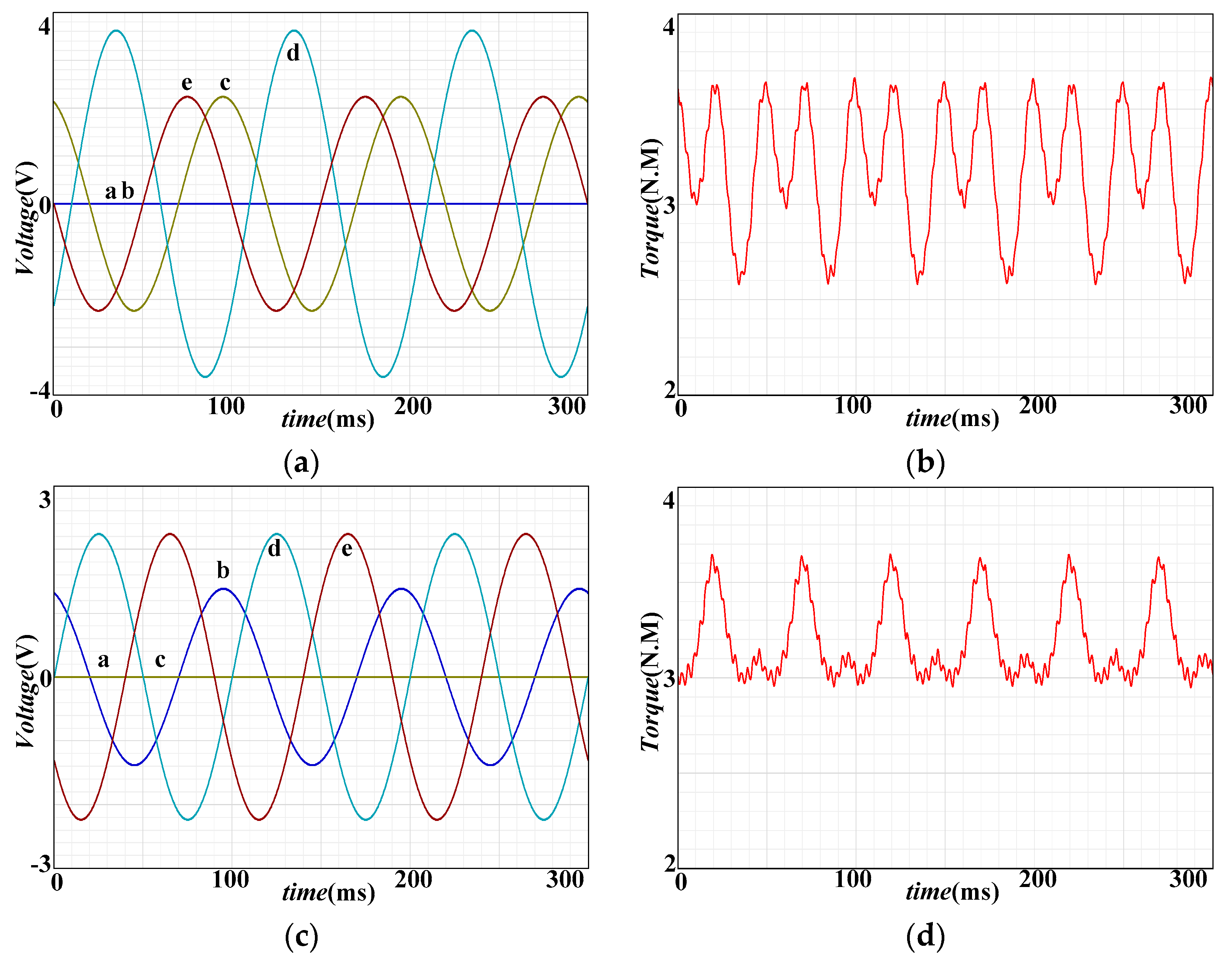
Figure 8. Single open-phase simulation results are shown in
Figure 9: (
a) and (
b) are the fault-tolerant current and torque with MCL; (
c) and (
d) are the fault-tolerant current and torque with MTO. The simulation results of two open-phase simulation results are shown in
Figure 10: (
a) and (
b) are the fault-tolerant current and torque of adjacent two-phases (AB); (
c) and (
d) are the fault-tolerant current and torque of non-adjacent two-phase AC.
Among the current waveforms, red is phase A, dark blue is phase B, yellow-green is phase C, light blue is phase D, and brown is phase E. The simulation results show that when compared with a normal operation state, the second and fourth torque ripple of two kinds of single open-phase fault-tolerant currents increase. The torque ripple of MCL and MTO fault-tolerant current is basically equal in value—about 0.4N.M. The torque of MTO control is only slightly larger at the wave peak than that of MCL control. The waveform of two-phase fault-tolerant current show that compared with that of single-phase fault-tolerant, the torque ripple of two-phase fault-tolerant is larger. Besides, the torque ripple of the adjacent two-phase fault-tolerant is larger than that of the non-adjacent two-phase fault-tolerant. The torque ripple of the adjacent two-phase fault-tolerant control is about 1N.M. and that of the non-adjacent two-phase control is about 0.6N.M. It can be seen that the non-adjacent two-phase fault-tolerant performance is better, so the transformation of the adjacent two open-phase to non-adjacent two open-phase is a performance improvement method. All the current waveforms in the diagram are consistent with the simulation and all kinds of fault-tolerant currents. The results of finite element simulation are in good agreement with Equations (29)–(32), which verifies the correctness of the analysis of torque ripple.
To verify the correctness and validity of the torque ripple compensation method, the two-phase fault-tolerant AC scheme, which has larger torque ripple, is compensated. The current laws satisfies Equation (33), where
k1 = 1.1756 and
k2 = –0.61. The current and torque waveform simulated by the finite element method in
Figure 11 shows the current and torque waveform of the torque ripple compensation method based on the normal decoupled AC open-phase fault-tolerant algorithm, in which the current fault-tolerant control law satisfies Equation (33). (
a) shows that the fault-tolerant current is no longer a pure sinusoidal current. (
b) shows that the torque compensation strategy can completely and effectively suppress the torque ripple caused by the third harmonic magnetic potential. The simulation verifies the correctness and effectiveness of the fault-tolerant torque compensation.
6.3. Experiments
Based on the analysis and simulation of the current relationship under normal decoupled single-phase and two-phase fault-tolerant states, the correctness of the fault-tolerant operation strategy and stability of speed switching are verified. As shown in
Figure A1, a five-phase PMSM experimental platform based on Infineon 32-bit MCU TC1767 is built. The motor parameters are shown in
Table 1. Bus voltage is 100 V, and moment of inertia is
J = 0.006 kg·m
2.
Experiment 1: Single-phase fault-tolerant experiment. Because the normal decoupling fault-tolerant control does not need a new reduced order transformation matrix, it can achieve arbitrary switching between normal operation and various fault-tolerant operations just by using different fault-tolerant current controls. Given a speed of 100 rpm, load of about 3N.M, and under speed closed-loop operation condition, the experiment switches from normal operation to phase A open circuit, then to minimum copper loss fault-tolerance, and finally to maximum torque output fault-tolerance. The correctness of the fault tolerance algorithm is verified by the current waveform, and the fault tolerance effect is determined by the speed waveform.
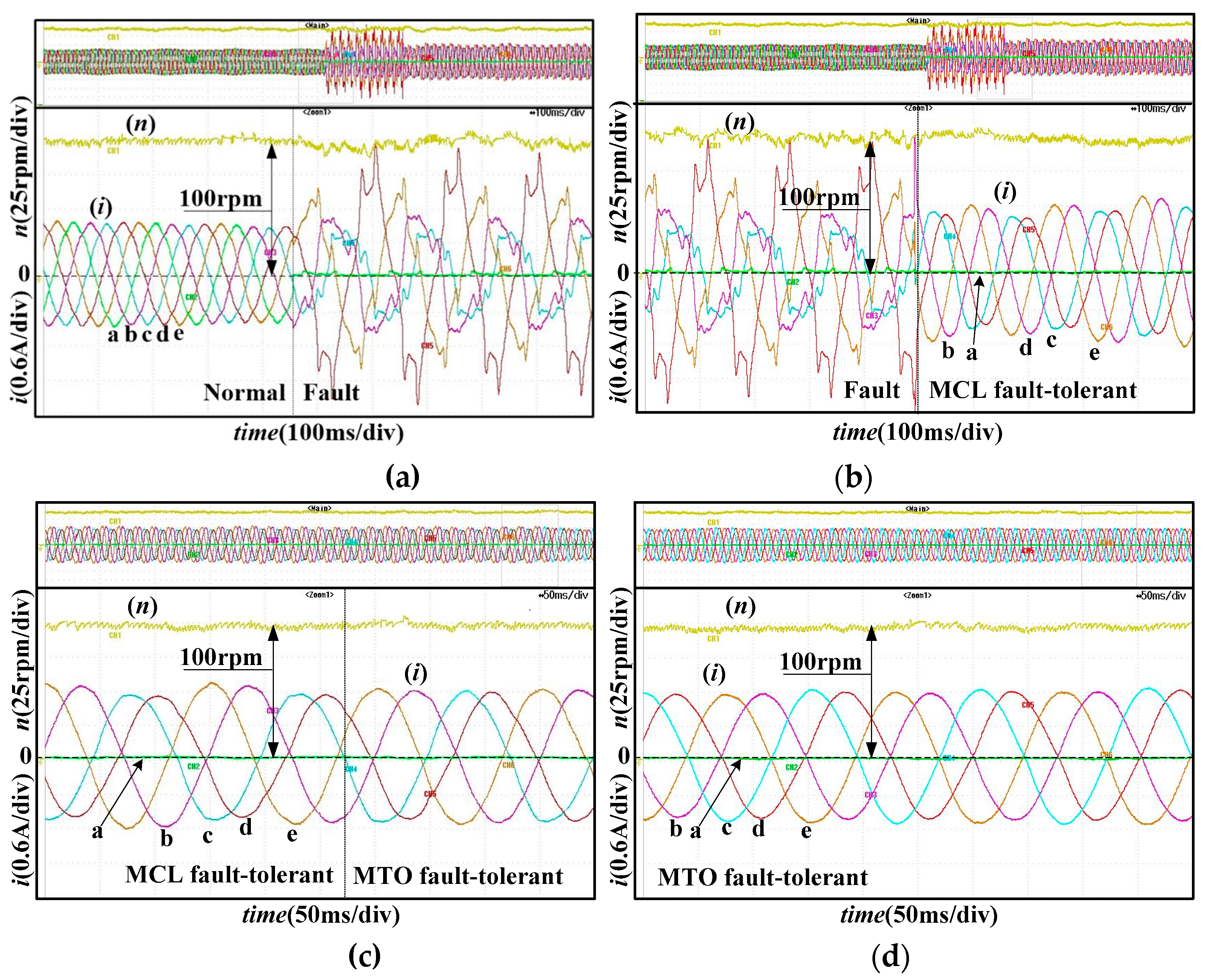
Figure 12 shows the current and velocity waveforms during the experiment.
Figure 12a shows the current and rotational speed waveforms when running from full-phase state to single open-phase state. It can be seen that without a fault-tolerant algorithm, the current is disordered and the rotating speed appears to be large waveforms, due to the influence of the control loop.
Figure 12b shows the current and speed waveform when switching to the minimum copper loss fault tolerance control after failure occurs. The experimental current waveform is consistent with the theory, and the rotating speed is stable.
Figure 12c gives the dynamic switching process of the two fault-tolerant algorithms. The current waveform shows the correctness of the fault-tolerant switching. The speed waveform verifies the free switching of the normal decoupling fault-tolerant algorithm.
Figure 12d gives steady-state current and speed waveforms of the maximum torque output (constant amplitude) fault-tolerant control. From the overall single-phase fault-tolerant speed waveform, it can be seen that the second and fourth harmonics of single-phase fault-tolerant torque ripple are not an obvious reaction to the speed.
Experiment 2: Becausetwo open-phase faults lead to a locked rotor under the current load, for safety reasons, when connecting or disconnecting phase C or B, the motor directly enters the corresponding normal or fault-tolerant state. The experimental results of two open-phase fault-tolerant(AC and AB) are shown in
Figure 13.
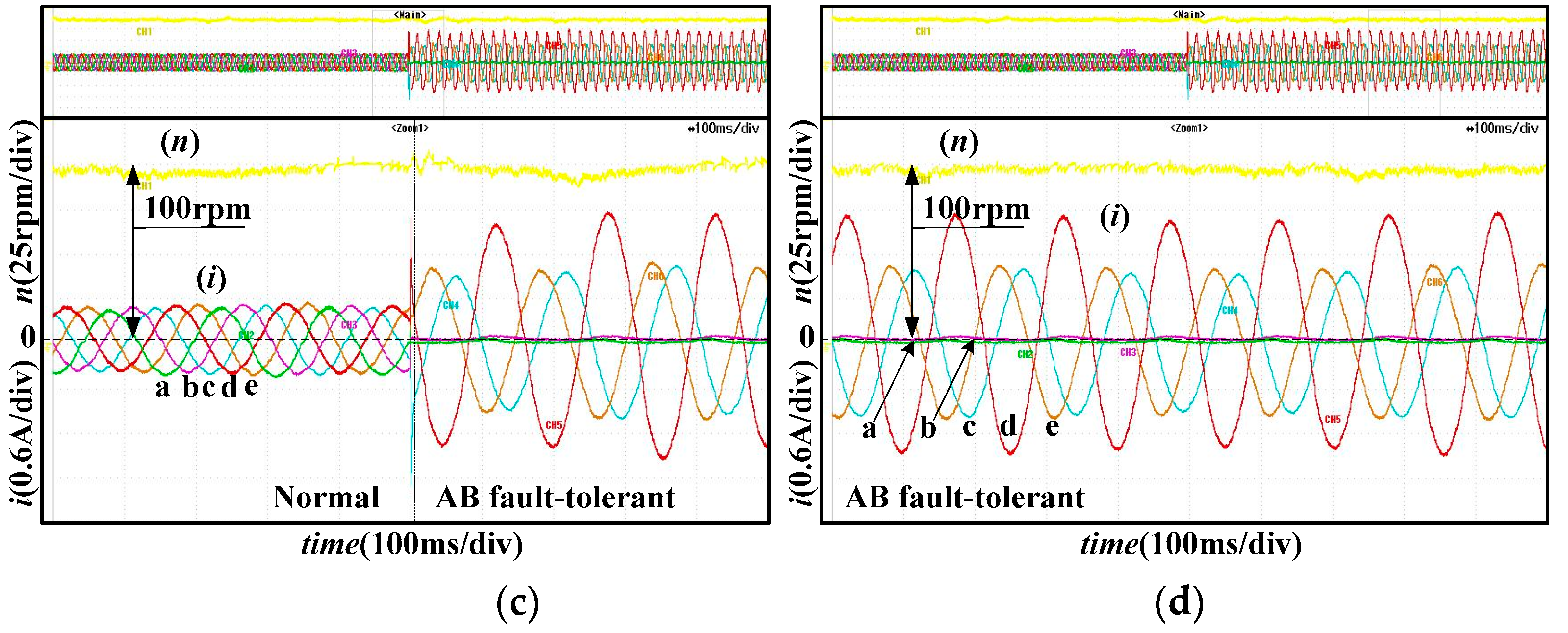
Figure 13 shows the current and speed waveforms of two open-phase fault-tolerant controls: (
a) shows the fault-tolerant current after switching from single open-phase to two open-phase fault-tolerant; (
b) is the waveforms after switching from the AC phase fault-tolerance to the A phase fault-tolerance, which shows that the speed transition is stable in the switching process; (
c) shows the switching process from normal state to AB fault-tolerant by directly disconnecting A and B phases under normal operation. The two adjacent open-phase condition has the worst performance that the maximum load will have. In
Figure 13, there were current spikes during the switching process, but no major speed fluctuations were observed, which shows the correctness of the two open-phases fault-tolerant strategy.
Figure 14 shows the transformation process of the current control law during the experiment, and all current outputs are DA waveforms. The experimental results verify the correctness of the unified fault-tolerant control law.
Figure 14 shows the transformation process of the current control law during the experiment, and all current outputs are DA. The experimental results verify the correctness of the unified fault-tolerant control law.
Experiment 4: AC fault-tolerant torque ripple compensation experiment. Under the condition of AC open-phase fault, it switches from the state of AC fault-tolerant to a state with torque ripple compensation.
Figure 15a shows the waveforms after switching from the AC phase fault-tolerance to the AC phase fault-tolerance with torque compensation(AC TC), which shows that speed transition is much more stable after switching.
Figure 15b shows the speed and phase current under the AC TC fault-tolerant method.
7. Conclusions
This paper takes sinusoidal a five-phase PMSM as the research object. Because voltage, torque, and flux linkage are not affected when the original decoupling matrix remains unchanged in an open-circuit fault, a normal decoupling unified fault-tolerant control strategy with low torque ripple is proposed. This strategy can be applicable to a variety of open-phase faults and can achieve smooth switching between normal and multiple open-phase fault-tolerant states. The torque ripple of unified fault-tolerant control is further analyzed. Based on the formula of torque ripple, a unified open-phase fault-tolerant control method with torque compensation is proposed to suppress the torque ripple. Then, the relationship between fault-tolerant current and all kinds of open-phase control laws is verified by simulation. Moreover, the torque ripple under normal decoupling state and the effect of TC are simulated by finite element simulation, which verifies the validity and correctness of compensation methods. Finally, the experiments on the condition of single-phase, adjacent two-phase, and non-adjacent two-phase open circuit verifies the correctness and stability of the proposed control strategy.
(1) A unified fault-tolerant control method based on normal decoupling is proposed, which is suitable for many kinds of open-phase faults. Because reduction of the dimension or change in the transformation matrix is not required, the complexity of fault-tolerant algorithm is greatly reduced, and smooth switching of normal and open-phase fault-tolerant states can be conveniently realized. The correctness of the fault-tolerant algorithm is verified by experiments, and the stable switching of various fault tolerant algorithms is realized.
(2) The torque of five-phase PMSM in normal decoupling model under open-phase fault-tolerant states is analyzed, and the unified open-phase fault-tolerant torque ripple formula is given. The correctness of the formula is verified by finite element simulation.
(3) Based on the formula of torque ripple, a unified open-phase fault-tolerant control method with torque compensation is proposed to suppress the torque ripple. The results of the finite element simulation and experiment can confirm the correctness and effectiveness of this method.


