Research on Switching Interconnection Modes and Game Control of Interconnected Air Suspension


School of Automotive and Traffic Engineering, Jiangsu University, Zhenjiang 212013, China
*
Author to whom correspondence should be addressed.
Energies 2019, 12(17), 3218; https://doi.org/10.3390/en12173218
Submission received: 16 July 2019
/
Revised: 19 August 2019
/
Accepted: 19 August 2019
/
Published: 21 August 2019
(This article belongs to the Special Issue Electronic Systems and Energy Harvesting Methods for Automation, Mechatronics and Automotive)
Abstract
:To solve the contradiction between handling stability and ride comfort of vehicles with interconnected air suspension system (IASS) and reduce the energy consumption of air suspension with adjustable spring stiffness, a coordinated control for dynamic performance was designed based on the logic of switching interconnection modes and game control for the damper. The control system consists of a switching controller for air suspension interconnection modes and a distribution controller for the damping force. The switching controller determines the optimal air suspension interconnection mode by calculating the vehicle dynamic performance index in real-time. The distribution controller achieves a distribution for optimal damping force based on an infinite time differential game. veDYNA software that is a vehicle dynamics analysis software based on MATLAB/Simulink was used to verify the algorithm, and the accuracy was verified by a bench test. Finally, the results show this coordinated system can significantly improve the ride comfort and restrain the pitching motion. Compared with traditional suspension, the vertical acceleration decreases by 18.32% and the dynamic stroke decreases by more than 10% under the straight condition; the vertical acceleration decreases by 12.24% and the roll angle decreases by 1.26% under the steering condition.
1. Introduction
With the increasing demand for vehicle ride comfort, more and more automobiles are equipped with an air suspension system [1]. The improvement in ride comfort often leads to the decline of handling stability. Air suspension can adjust its stiffness by filling and releasing an air spring, which can realize the control of body attitude and improve handling stability [2]. But this method needs an air compressor, gas tank and so on, and the complex structure needs a significant quantity of energy. The interconnected air suspension system (IASS) with coordinated control designed in this paper can change the stiffness of the air spring and greatly reduce the energy consumption by controlling the opening and closing of four solenoid valves. Compared with active suspension, there is no need for an actuator to consume significant energy. It only needs a differential game to control the damping force, which can achieve good results and reduce the cost.
The IASS not only has excellent performance in vibration isolation but can also adjust the roll and pitch stiffness by switching the interconnected modes of the air springs to maximize the performance of the air suspension. It has attracted significant attention from scholars [3,4,5,6,7]. The IASS is mainly used in sports utility vehicles based on its advantages, such as the third generation of Range Rover L322 [8]. Because of the gas exchange between air springs, the coupling relationship between system variables is complex. The corresponding control theory is not perfect, so it is seldom used in other vehicles. The realization of the control method for this suspension structure is the focus of this paper. Switching to the optimal interconnection mode according to the information of the vehicle can alleviate the contradiction between ride comfort and handling stability to a certain degree. If the optimal interconnection mode is combined with reasonable output of the damping force, the dynamic performance of the vehicle will be further improved. The suspension can improve the handling stability by controlling the output damping force of the damper under the steering condition. However, if the damping force is too large, the body can quickly restore balance, but drivers will feel uncomfortable. If the damping force is too small, the body will roll over [9]. At this time, there is a contradiction between ride comfort and handling stability. Therefore, a damping force distribution controller is designed based on a differential game method. By adjusting the optimum damping force, the balance of the vehicle body is slowly restored to ensure its comfort, and the vehicle is in a safe state without rollover. By constantly adjusting the damping force according to vehicle information, the vehicle will transition smoothly from a steering condition to a straight condition. Coordinating the dynamic performance of vehicles is an important basis to ensure good operation of the IASS. In this paper, the coordination of vehicle dynamic performance was realized by switching four different interconnection modes of the IASS and controlling the damping force of the adjustable damper.
Researchers found that the requirements of suspension in vehicle ride comfort and handling stability is contradictory, which affects the dynamic performance of vehicles. They began to design the coordinated optimal control of vehicle ride comfort and handling stability to resolve the conflict [10,11,12,13]. On the one hand, some scholars chose an appropriate evaluation index to optimize control systems. Using vertical acceleration and roll angle as the optimization index of ride comfort and handling stability, Zhao [14] established a control strategy for adaptive stiffness of air suspension, which improves the vehicle handling stability very well. In addition, Zeng [15] put forward the comprehensive performance index of the vehicle system by combining the pavement vibration stability index with traditional indices and achieved coordinated control by controlling the suspension force. Although the indicators they selected and designed have improved the dynamic performance of the vehicle to some extent, the indicators are not comprehensive enough. In this paper, the ride comfort indices (vertical acceleration, dynamic stroke, dynamic load) and the handling stability indices (body pitch angle, body roll angle, and yaw rate) are taken into account, and the designed comprehensive index is more specific. On the other hand, scholars mainly use the genetic algorithm [16], linear quadratic regulator (LQR) algorithm [17], fuzzy proportional integral derivative (PID) algorithm [18], and other control methods [19] to design a suspension controller for achieving coordinated control of ride comfort and handling stability, but few use game theory as a control. Ride comfort and handling stability are two contradictory sides, as one falls and the other rises. The coordinated control of vehicle ride comfort and handling stability is essentially a game. Both ride comfort and handling stability try to maximize their own state by changing suspension characteristics, which is very suitable for using game theory as a control.
Game theory is a mathematical method for calculating the benefits of various possible decisions for conflict problems. It has been well applied in many fields, such as power system dispatch [20], wireless networks [21], vehicle control systems [22,23]. Based on game theory, the contradiction between ride comfort and handling stability can be expressed in the form of function. Solving this problem from the angle of mathematical analysis can effectively coordinate the dynamic performance of vehicles. A vehicle suspension system with interconnected air spring and the adjustable damper is studied in this paper, which is a continuous-time system. Differential game is a dynamic game method to solve the problem of a continuous-time system [24]. Therefore, the coordination game model of ride comfort and handling stability is established by differential game theory in this paper. Considering the suspension stops working at random during vehicle running and the game under deterministic factors, the game is an infinite-time differential game.
In this paper, a coordinated control system for dynamic performance of the IASS is designed. First, the composition and principle of the IASS are introduced. The whole vehicle simulation model, including interconnected air spring and interconnected pipelines, is established. After making the simulation analysis of IASS under different interconnected modes, the change rule of comprehensive evaluation indices is obtained. Then the interconnected modes switching controller is designed, and the damping force distribution controller based on the differential game is designed. The coordinated controller composed of these two controllers can well coordinate the contradiction between ride comfort and handling stability by analyzing the simulation results. Finally, the effectiveness of this coordinated control is further confirmed by the establishment of a test bench of IASS.
2. The Structure and Working Principle of IASS
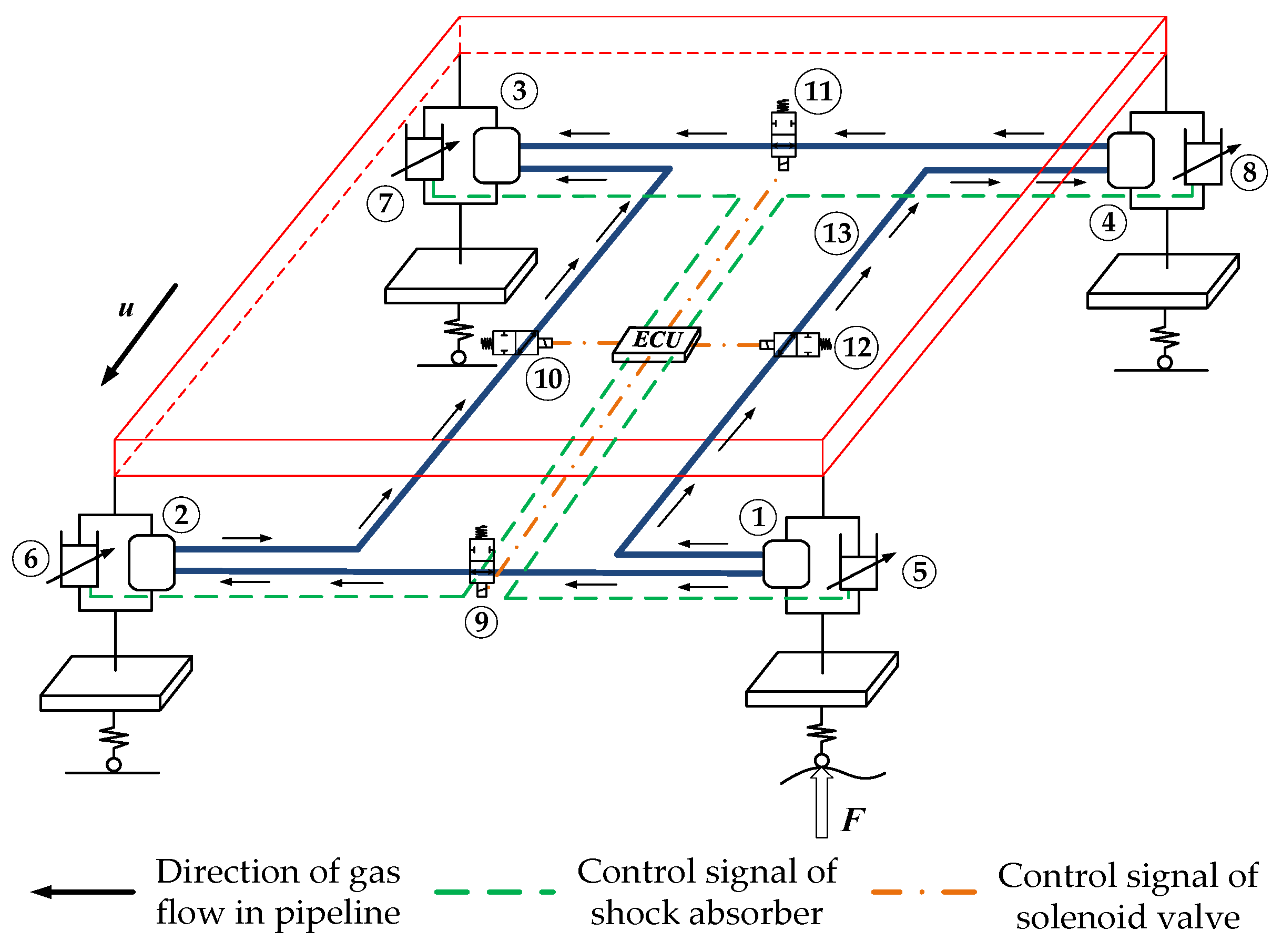
The IASS, as shown in Figure 1, is mainly composed of four air springs (①,②,③,④), four adjustable dampers (⑤,⑥,⑦,⑧), four solenoid valves (⑨,⑩,⑪,⑫), interconnected pipelines (⑬) and an Electronic Control Unit (ECU). Based on the traditional air suspension system, the adjacent air spring is connected by pipelines [25]. ECU changes the interconnection mode of the IASS by opening and closing the solenoid valves in the pipeline. When all solenoid valves are opened, air suspension is a four-corner interconnection; when all solenoid valves are closed, air suspension is non-interconnected; when solenoid valve ⑩ and ⑫ are opened and solenoid valve ⑨ and ⑪ are closed, air suspension is a longitudinal interconnection; when solenoid valve ⑨ and ⑪ are opened and solenoid valve ⑩ and ⑫ are closed, air suspension is a lateral interconnection. In addition, the damping force of damper can be adjusted according to the running condition of the vehicle. The aim is to further improve the performance of IASS.
When the front left wheel meets a bump on the road, the front left part of the vehicle is raised. At the same time, the air spring at the front left suspension is compressed, and the gas in the chamber flows to the rear left air spring and the front right air spring due to the air pressure difference, as shown by the arrow in Figure 1. Due to the inflow of gas, the air pressure in the rear left air spring and the front right air spring increases. Part of the gas will flow into the rear right air spring, which converts the increase in the height of a single wheel into the increase in the overall height of the body. Because of the connecting of the pipelines, the gas pressure in the four air springs can remain the same for a short time under different excitations. As a result, the vehicle body can always maintain a uniform level. The vertical motion of the body is weakened, and the ride comfort of the vehicle is greatly improved.
3. Vehicle Dynamics Model of the IASS
3.1. Vehicle Dynamics Model
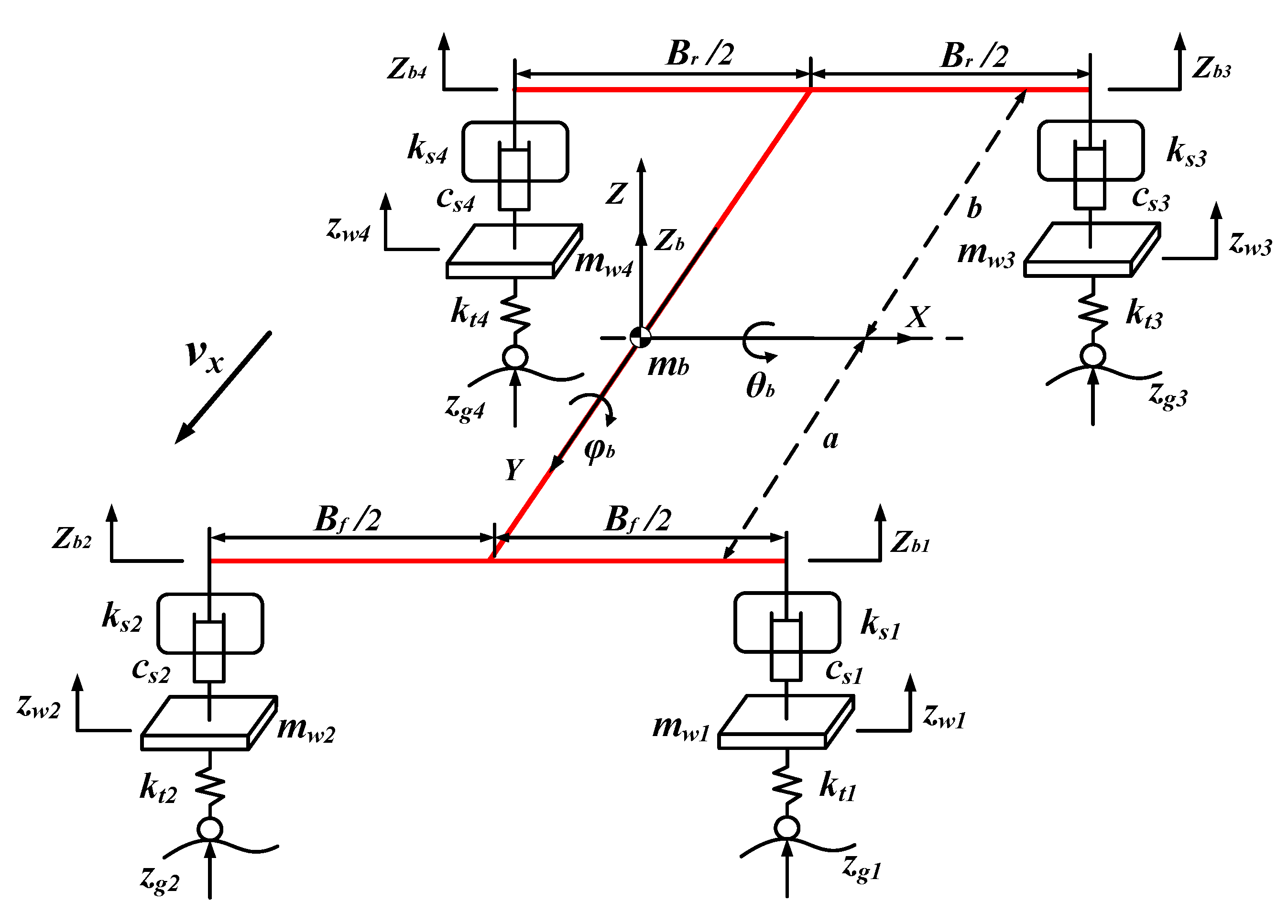
To better describe the ride comfort and handling stability of the vehicle with IASS, the vehicle body is regarded as a rigid body. The vibration caused by the frame is not considered, and the non-linear factors of the tire are neglected. Moreover, the effects of feedback from seats and vehicle power assembly are removed, and the vehicle model is simplified appropriately. In this paper, the 7 degrees of freedom model of the vehicle, which includes vertical motion, roll motion, and pitch motion of sprung mass and vertical motion of four unsprung mass, was adopted. As shown in Figure 2.
Based on Newton’s law of motion, a set of dynamic Equations is established according to the defined coordinate system.
When the pitch angle and roll angle are small, the vertical displacement at the four corners of the body has the following relationship:
where i = 1,2,3,4, and they represent the front left, the front right, the rear left, and the rear right, respectively. zb is the vertical displacement of body centroid, zbi is the vertical displacement of the four corners of the vehicle body, a is the distance from the body centroid to the front axle, b is the distance from the body centroid to the rear axle, θb is the pitch angle, ϕb is the roll angle, Bf is the front wheel tread, Br is the rear wheel tread.
The vertical motion Equation of body centroid:
The pitching motion Equation of vehicle body:
The rolling motion Equation of vehicle body:
The vertical motion Equation of unsprung mass:
where mb is body quality, mw is unsprung mass, Jϕ is the roll moment of inertia, Jθ is the pitch moment of inertia, kti is the tire stiffness, kts is the stiffness of the air spring, csi is the damping coefficient of the shock absorber, zwi is the vertical displacement of the wheel, zgi is the vertical excitation of the pavement.
According to Equations (1)–(5), the differential Equation of the 7 degrees of freedom model can be sorted out as the following matrix:
The system state variable x is:
The control input is: , Fi is the damping force.
The disturbance variable is: ,
where
3.2. Interconnected Air Spring and Pipeline Model
The air spring has less heat transfer with the outside during its working process, so the process can be regarded as an adiabatic process approximately. Therefore, the gas in the air spring can be taken as an open adiabatic system with fixed mass [26].
According to the first law of thermodynamics, the air pressure state Equation of each air spring is deduced as follows:
where Pi is the fluid pressure in the air springs, Pi0 is the initial pressure, Vi is the volume of each air spring, Vi0 is the initial volume in the chamber, mi is the gas mass in the air springs, mi0 is the initial gas mass.
The spring force of the air spring is as follows:
Among, , where F is the spring force produced by the air spring, A1 is the effective area of the air spring, P0 is the atmospheric pressure, d is the height variation of the air spring, dVi/dh is the volume height change rate of the air spring.
The air spring in the IASS is connected through the pipeline. Throttle effect and viscous effect occur in the gas exchange [27].
When the throttling effect of the pipeline is considered as a throttle orifice, the mass flow of gas flow through the throttle orifice is expressed as follows:
Among, , where A is the effective flow area, Se is the flow coefficient, 0.62, Pup is the upstream gas pressure, Pdown is the downstream gas pressure, Tup is the upstream gas temperature, D is the inside diameter of the interconnected pipeline, R is the ideal gas constant, 287 N·m/(kg·K).
Taking into account the pressure loss and time delay in the operation of air suspension, the function of gas mass flow at different locations of the pipeline with time is obtained as follows:
where L is the length of connecting pipelines, Tdown is the downstream gas temperature, Vc is the sound velocity, 340 m/s, Rt is the friction factor of gas on the inner wall of the pipeline.
4. Design of Coordinated Vehicle Dynamic Performance Control System
4.1. General Design
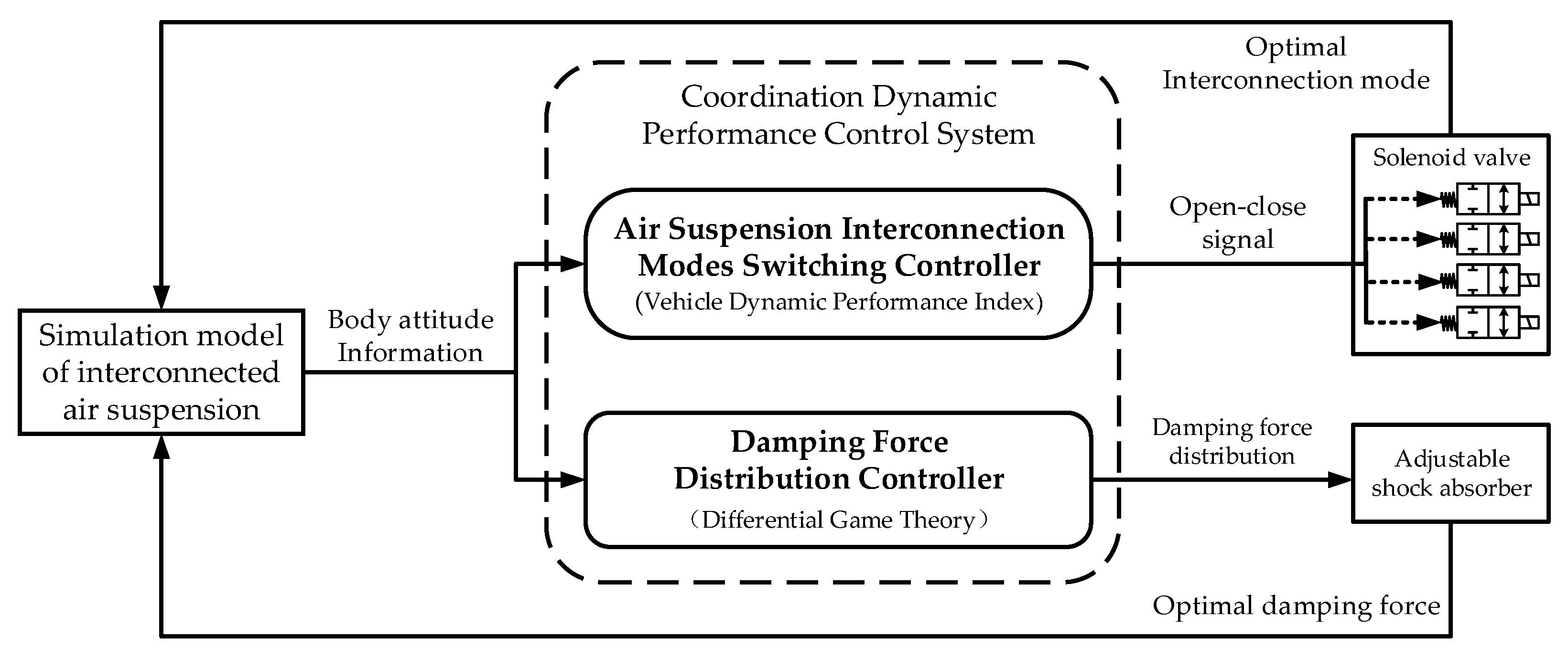
The coordinated dynamic performance control system of IASS is composed of a switching controller for air suspension interconnection modes and a distribution controller for the damping force. The switching controller chooses the corresponding optimal air suspension interconnection mode by calculating the comprehensive evaluation indices of vehicle ride comfort and handling stability in real-time. This controller not only ensures the ride comfort but also restrains the drastic change of body attitude. At the same time, the damping force distribution controller decides the distribution for optimal damping force to balance vehicle ride comfort and handling stability. Figure 3 is the control system of IASS for coordinating dynamic characteristics. This control system can improve the dynamic performance of the vehicle significantly and solve the contradiction between ride comfort and handling stability effectively.
4.2. Design of Air Suspension Interconnection Modes Switching Controller
The IASS realizes the switching of interconnected mode by controlling the opening and closing of solenoid valves in interconnected pipelines. When the vehicle is under a steering condition or an accelerate–decelerate condition, it can be seen that IASS will deteriorate handling stability. For example, under an accelerate–decelerate condition, the longitudinal interconnection of IASS will increase the pitch attitude of vehicles; under a steering condition, the roll attitude of vehicles is deteriorated when the interconnection mode of IASS is a lateral interconnection; under complex conditions (mixing the steering condition and the accelerate–decelerate condition), the four-corner interconnection leads to the increase of the pitch attitude and roll attitude. To solve this problem, it is necessary to switch to the optimal interconnection mode by controlling the solenoid valves under different working conditions.
4.2.1. Establishment of Comprehensive Indicators
To achieve the coordinated control of vehicle ride comfort and handling stability, it is necessary to design appropriate comprehensive evaluation indices according to vehicle drive cycle and body attitude. The comprehensive evaluation index for ride comfort mainly takes into account the acknowledged ride comfort index, such as vertical acceleration, dynamic stroke, and dynamic load. The sub-indices of the comprehensive evaluation index for handling stability mainly are pitch angle, roll angle, and yaw rate. However, because of the physical meaning, the dimensions and the functions trend to the comprehensive index of each sub-index are different, the dimensionless method must be used to deal with the problem to calculate the comprehensive evaluation index. The dimensionless method is a mathematical method to eliminate the influence of different dimensions of the original variables, which can unify different physical quantities [28]. Normalization method is chosen for dimensionless processing because it is the most widely used and effective method.
The normalization Equation is as follows:
where , .
The comprehensive evaluation index Ja for ride comfort and the comprehensive evaluation index Jb for handling stability are established respectively, as follows:
where fdi is the dynamic stroke, Fdi is the dynamic load, is the yaw rate.
4.2.2. Analysis of Comprehensive Indicators under Different Interconnection Modes
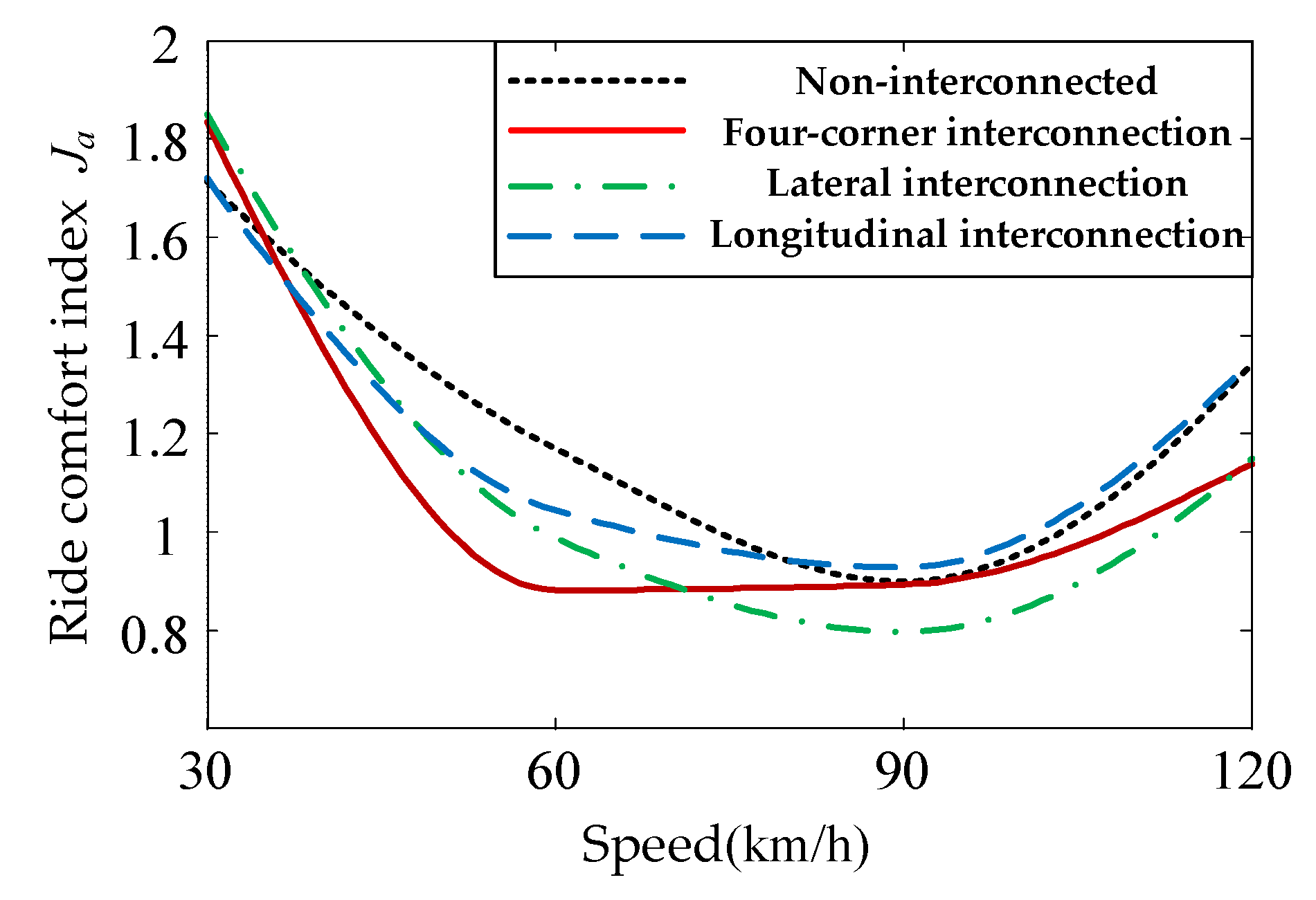
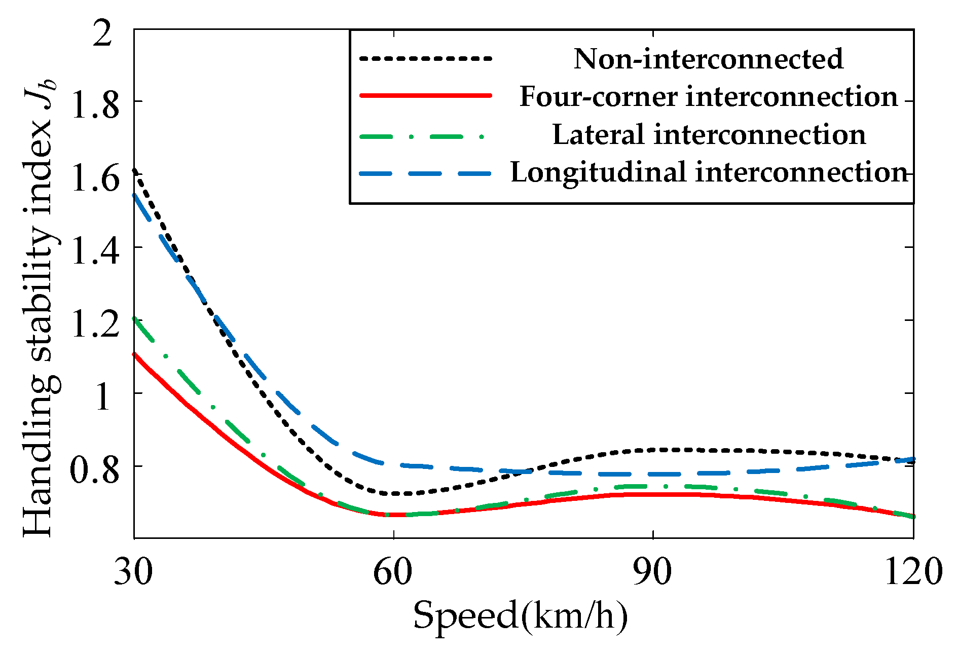
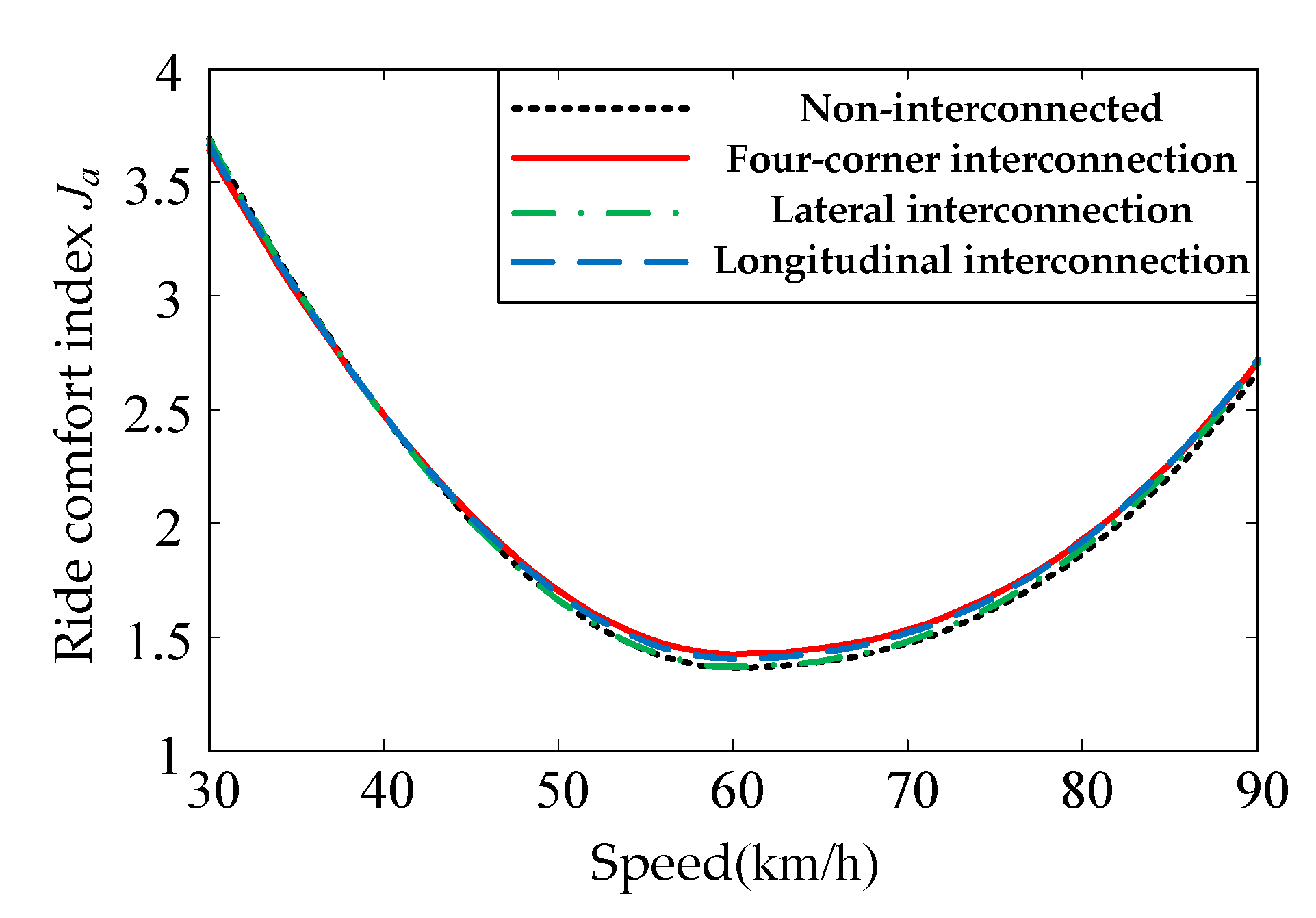
The vehicle dynamics simulation model of uncontrolled IASS was combined with veDYNA (R3.10.6) to analyze the change of comprehensive index under different interconnected modes. If the performance change of vehicles under standard-A/C road excitation was used as the evaluation index, it will lead to the threshold too large or too small, which will affect the function of switching suspension interconnection modes. There are many working conditions in vehicle running, so two typical working conditions, the straight condition, and the steering condition, were selected. Ja (30, 60, 90, 120 km/h) and Jb (30, 40, 50, 60, 70, 80, 90 km/h) at different speeds and are simulated, respectively. Figure 4, Figure 5, Figure 6 and Figure 7 are obtained by linear fitting. The lower the Ja, the better the ride comfort, and the higher the Ja, the worse the ride comfort. The lower the Jb, the better the handling stability, and the higher the Jb, the worse the handling stability.
When the steering angle |δ| < 10°, it is considered as a straight condition. When |δ| ≥ 10°, it is in steering running. The average value of each evaluation index under each working condition is selected as the switching threshold. As shown in Figure 4 and Figure 5, the change rules of the comprehensive indices Ja and Jb under the straight condition of standard-B road excitation are given. The switching thresholds of the ride comfort index Ja and the handling stability index Jb under the straight condition were 1.23 and 0.89, respectively. Figure 6 and Figure 7 provide the change rules of comprehensive indices Ja and Jb under the steering condition of standard-B road excitation. The switching thresholds of ride comfort index Ja and stability index Jb under the steering condition were 2.59 and 1.37, respectively
4.2.3. Logic of Interconnection Modes Switching
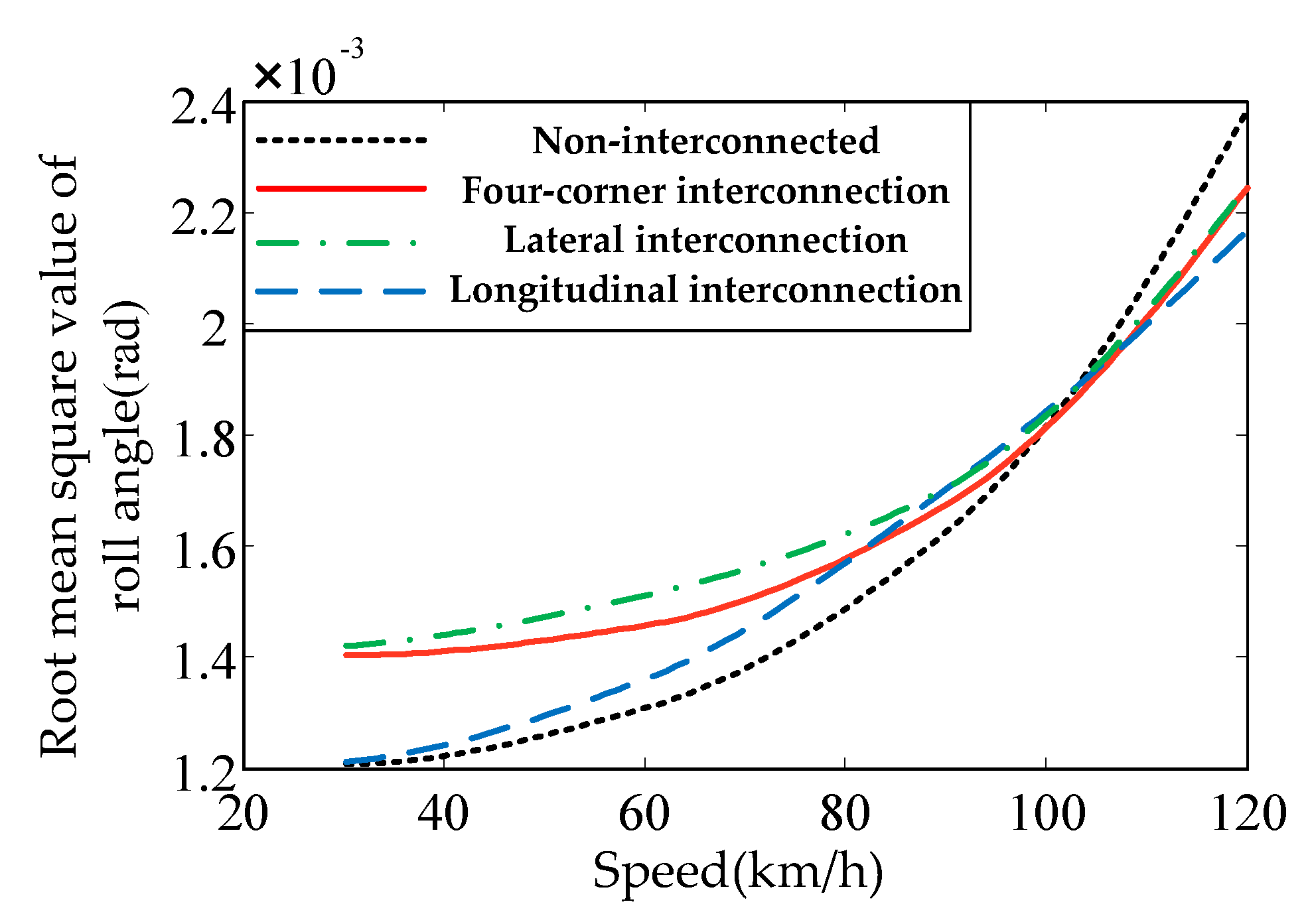
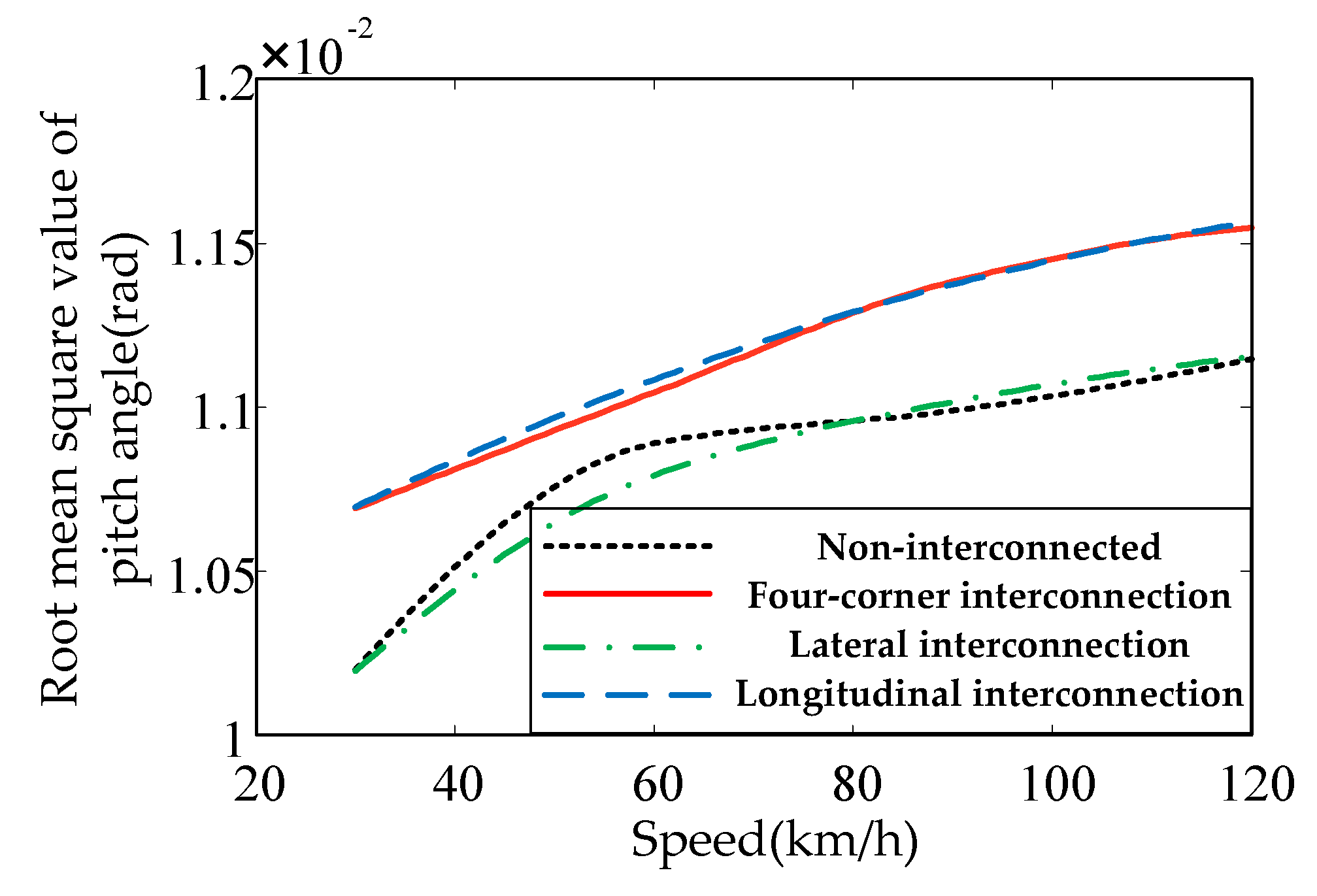
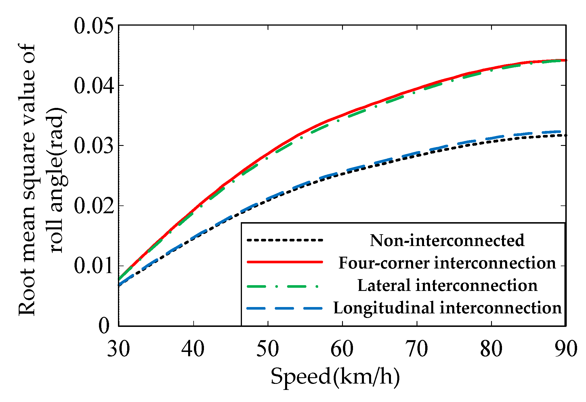
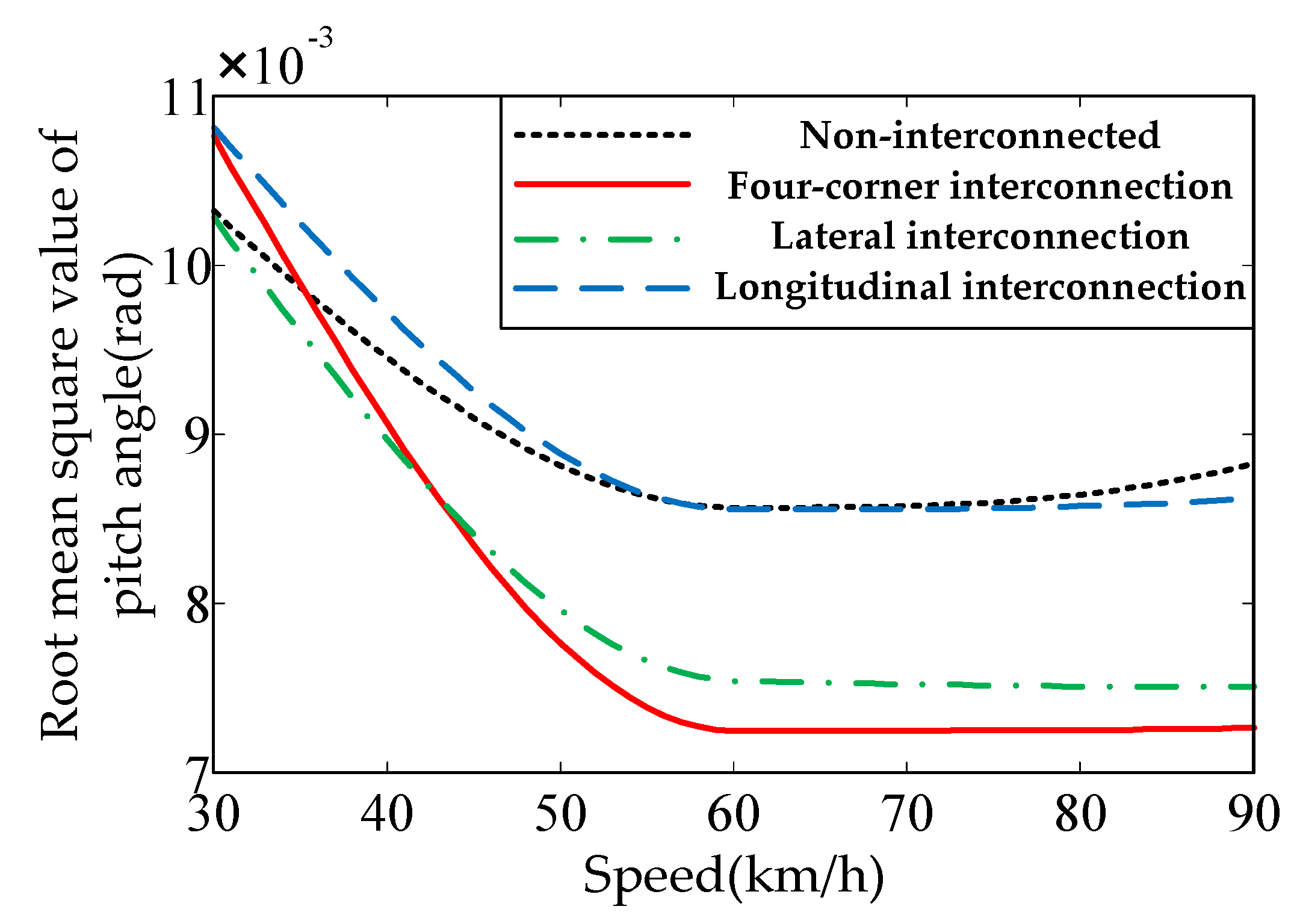
The average value of each evaluation index under each working condition is selected as the switching threshold to obtain the optimal switching threshold. As two contradictory parties, ride comfort and handling stability are interdependent and interrelated and can be transformed under certain circumstances. Therefore, by calculating Ja and Jb in real-time and comparing them with their respective thresholds, the main contradictions to be optimized are determined to obtain the optimal interconnection switching mode. When optimizing ride comfort performance is the main contradiction, the optimal suspension interconnection mode is selected according to the change of ride comfort comprehensive index. When the optimal control stability is the main contradiction, the roll angle θb and pitch angle ϕb are considered as its main aspects, which is to ensure the safety of vehicle body attitude. Similarly, the average value of the changes of roll angle and pitch angle are used as the switching threshold to determine the principal aspect and secondary aspect of the contradiction. Figure 8 and Figure 9 provide a change rule of pitch angle and roll angle under the straight condition in standard-B road excitation. It can be calculated that the switching thresholds of ride comfort index θb and handling stability index ϕb under the straight condition are 1.12 × 10⁻² and 2 × 10⁻³, respectively. Figure 10 and Figure 11 show the change rules of pitch angle and roll angle under the steady-state steering condition in standard-B road excitation. The switching thresholds of ride comfort index θb and handling stability index ϕb under the steady-state steering condition were 9.3 × 10⁻³ and 1.65 × 10⁻², respectively. The control strategy of switching air suspension interconnection modes is shown in Table 1.
4.3. Design of Damping Force Distribution Controller Based on Differential Game
The model was established by using differential game theory to describe the contradiction between ride comfort and handling stability. The output of the game model is the damping force. By solving the game model, the distribution of damping force, which can achieve the goal of coordinating the contradiction, is obtained. To show the contradiction between ride comfort and handling stability in the form of function, an infinite-time differential game model was established to coordinate the ride comfort and handling stability. J is the objective function of vehicle performance optimization. Its essence is the comprehensive performance of the vehicle’s optimal ride comfort and handling stability, and it is the payoff function of the game model. Considering the evaluation indices of vehicle ride comfort and handling stability, the objective function J of vehicle performance controller can be expressed as follows:
Equation (13) is a standard quadratic form, so a differential game model Γs for the coordination of ride comfort and handling stability can be expressed as:
where, , , .
There are three solutions for the Nash equilibrium in the infinite-time differential game model: open-loop Nash equilibrium, closed-loop Nash equilibrium, and feedback Nash equilibrium [29]. The complexity of feedback Nash equilibrium is moderate among the three solutions, and this solution does not need to consider the consistency of time, so it is very practical [30]. When the optimal damping force is obtained by using the feedback Nash equilibrium method, the optimal damping force depends only on the current moment and is not affected by the previous game situation.
The optimal index function of ride comfort and handling stability is used as the payoff function of the game, and the state Equation of the suspension system is used as the constraint. The distribution for optimal damping force is obtained by solving the Nash equilibrium solution of the established game model. η(τ) = {x(t), t0 ≤ t ≤ τ} is used to represent the state space of 7 degrees of freedom model of vehicle. Because its information structure belongs to CLPS (Closed Loop Perfect State) and the game model of suspension ride comfort and handling stability is an infinite-time game model with seven players, a set of 7-tuple strategies {ui*(τ) = ϕi*[x(τ)] ⊂ Ui, ∀ I∈Γs} was constructed as a feedback Nash equilibrium and the output is the optimal damping force of four adjustable dampers. If there exists a function J(t, x) defined in [0, ∞] × Rm, the feedback Nash equilibrium must satisfy the following conditions:
Assuming the existence of n × n order real symmetric matrix Pi and n × n order real symmetric matrix Yi, the following conditions for Riccati Equation are satisfied.
where , .
A quadratic linear soft suppression Nash equilibrium is solved as follows:
Furthermore, the distribution for optimal damping force of the adjustable damper in the coordination game between ride comfort and handling stability can be obtained as follows:
5. Simulation Analysis
The simulation experiment was carried out based on veDYNA to verify the effectiveness of the control system. The IASS model established in MATLAB/Simulink (R2016a) was used to replace the self-contained suspension model in veDYNA. To ensure the high fidelity of the dynamic performance of the vehicle model, other modules in veDYNA were not modified. The vehicle parameters are shown in Table 2, which are consistent with those of the bench test.
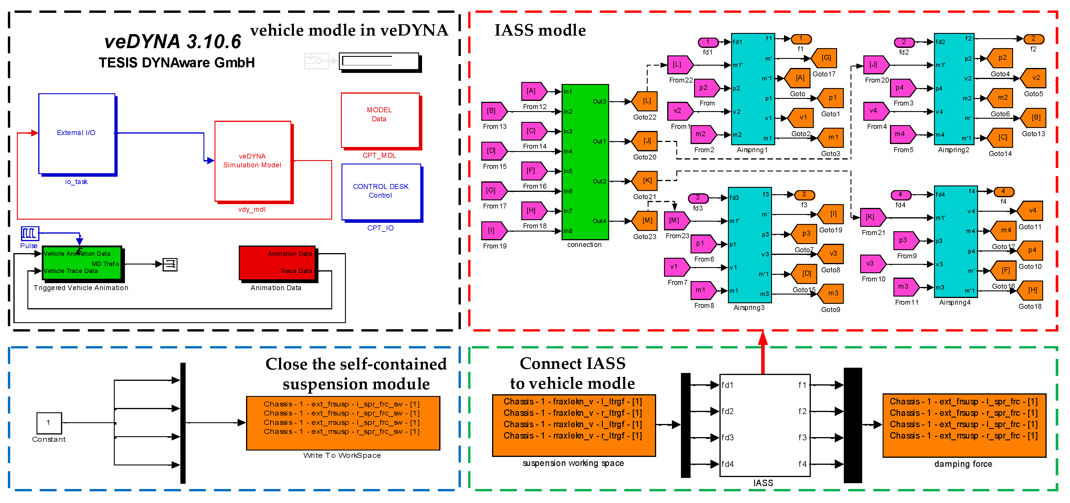
In veDYNA, ‘1’ was the application of an external suspension system, ‘0’ was the application of self-contained suspension system. In the Simulink software, the matrix command value [1, 1, 1, 1] of four suspensions using external power input were written, which can cut off the transmission of suspension force of the original vehicle and connect the established suspension model with the vehicle model. Vehicle model with IASS in veDYNA, as shown in Figure 12.
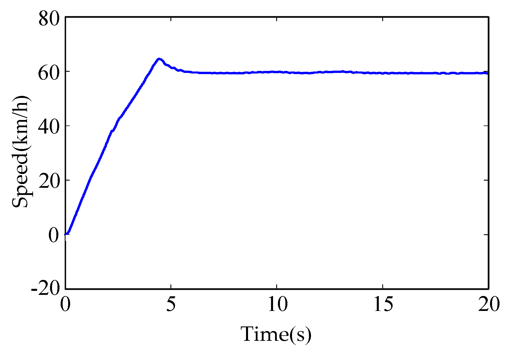
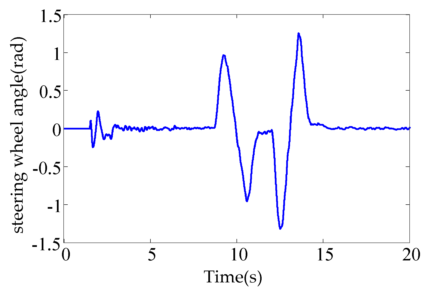
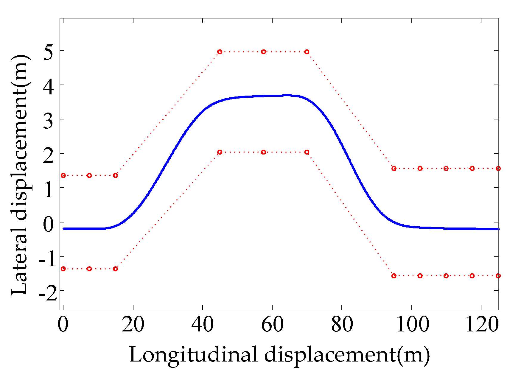
To simulate the actual driving conditions of the vehicle and verify the effectiveness of the control system accurately, the simulation was carried out under complex conditions (mixing the steering condition and the accelerate-decelerate condition). The simulation conditions were as follows: the road excitation is standard-B, and the adhesion coefficient of pavement is 0.8. The speed change is shown in Figure 13, the steering wheel angle change is shown in Figure 14, and the vehicle driving path is shown in Figure 15.
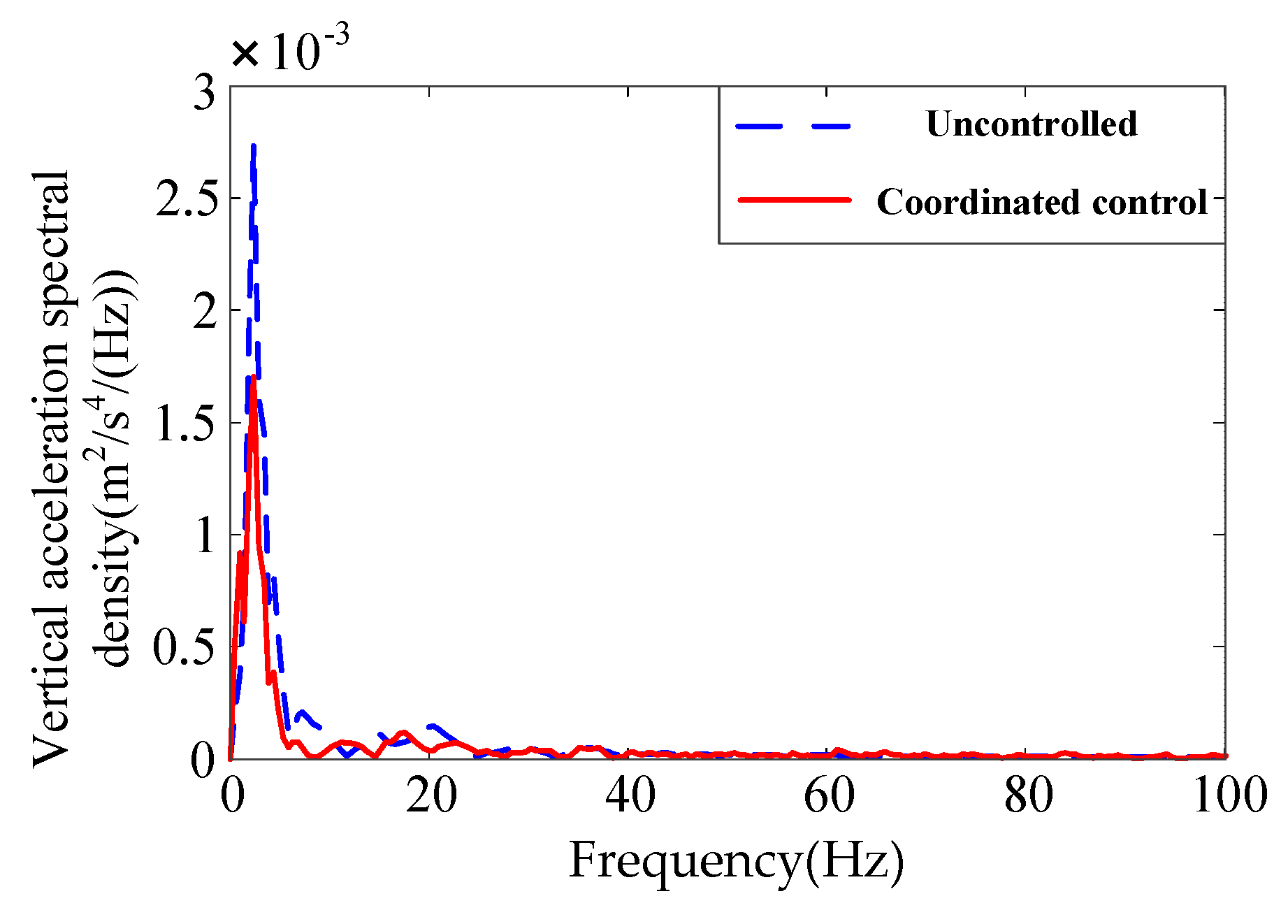
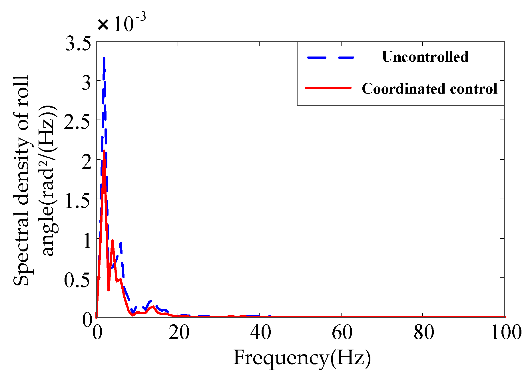
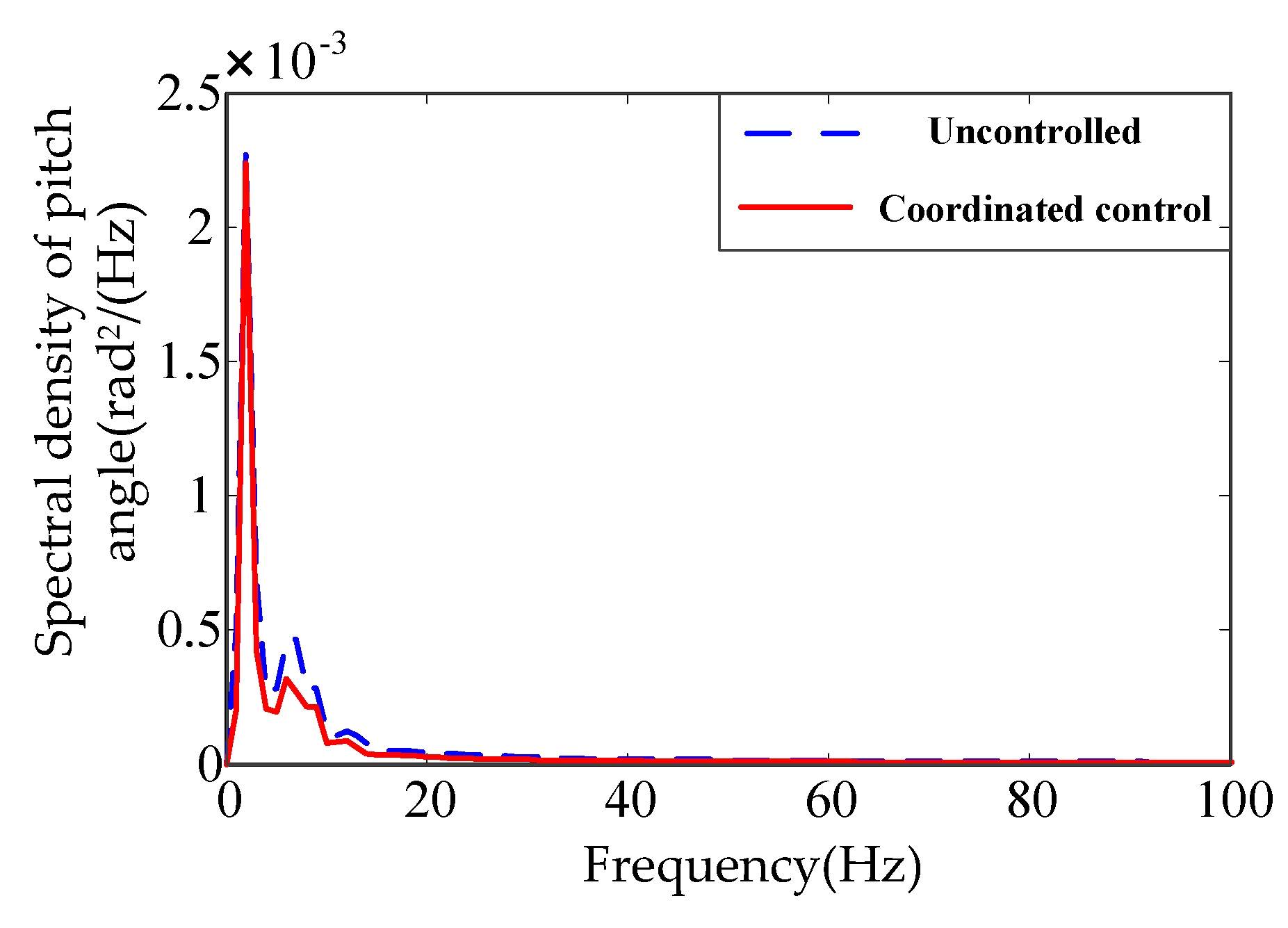
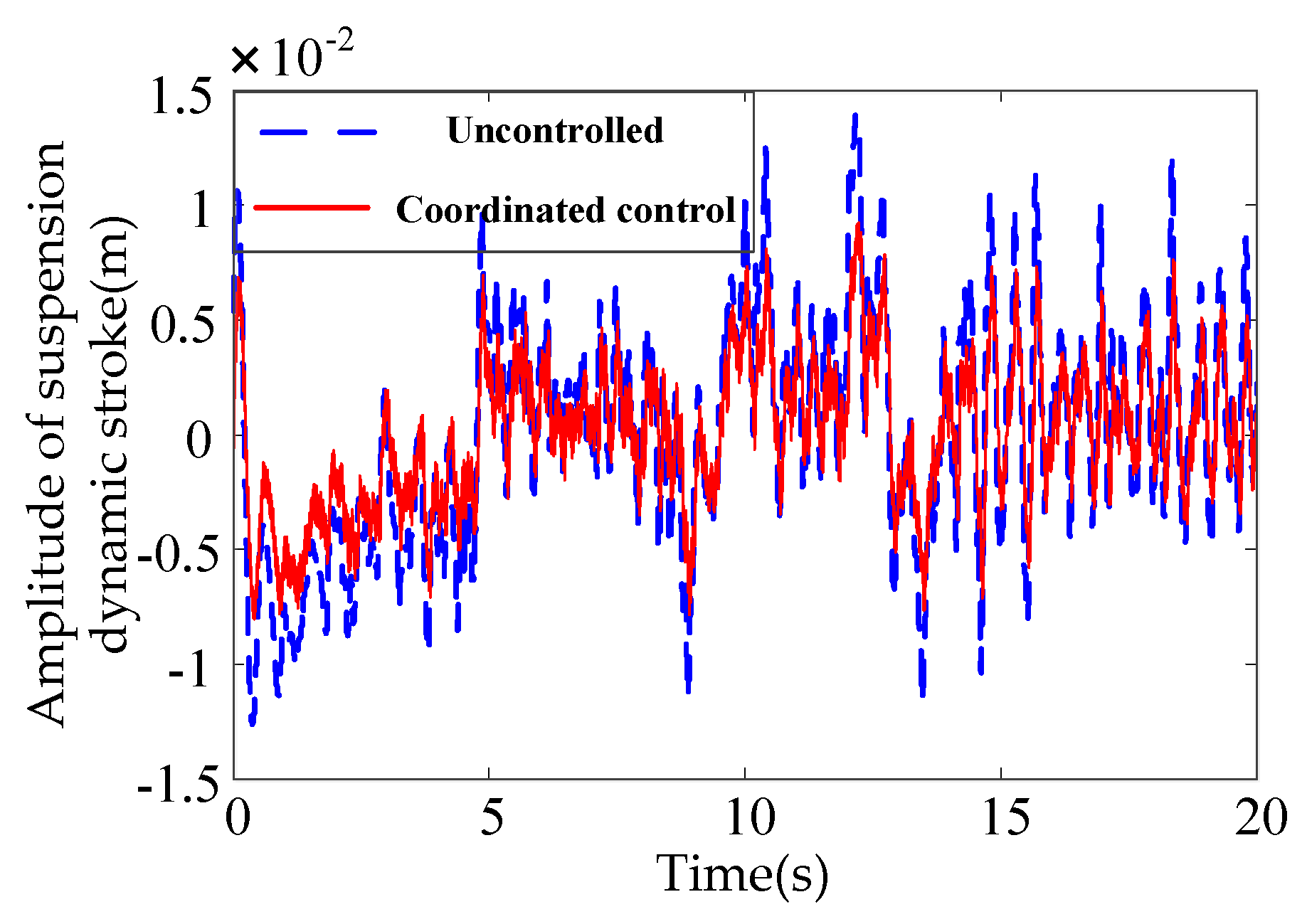
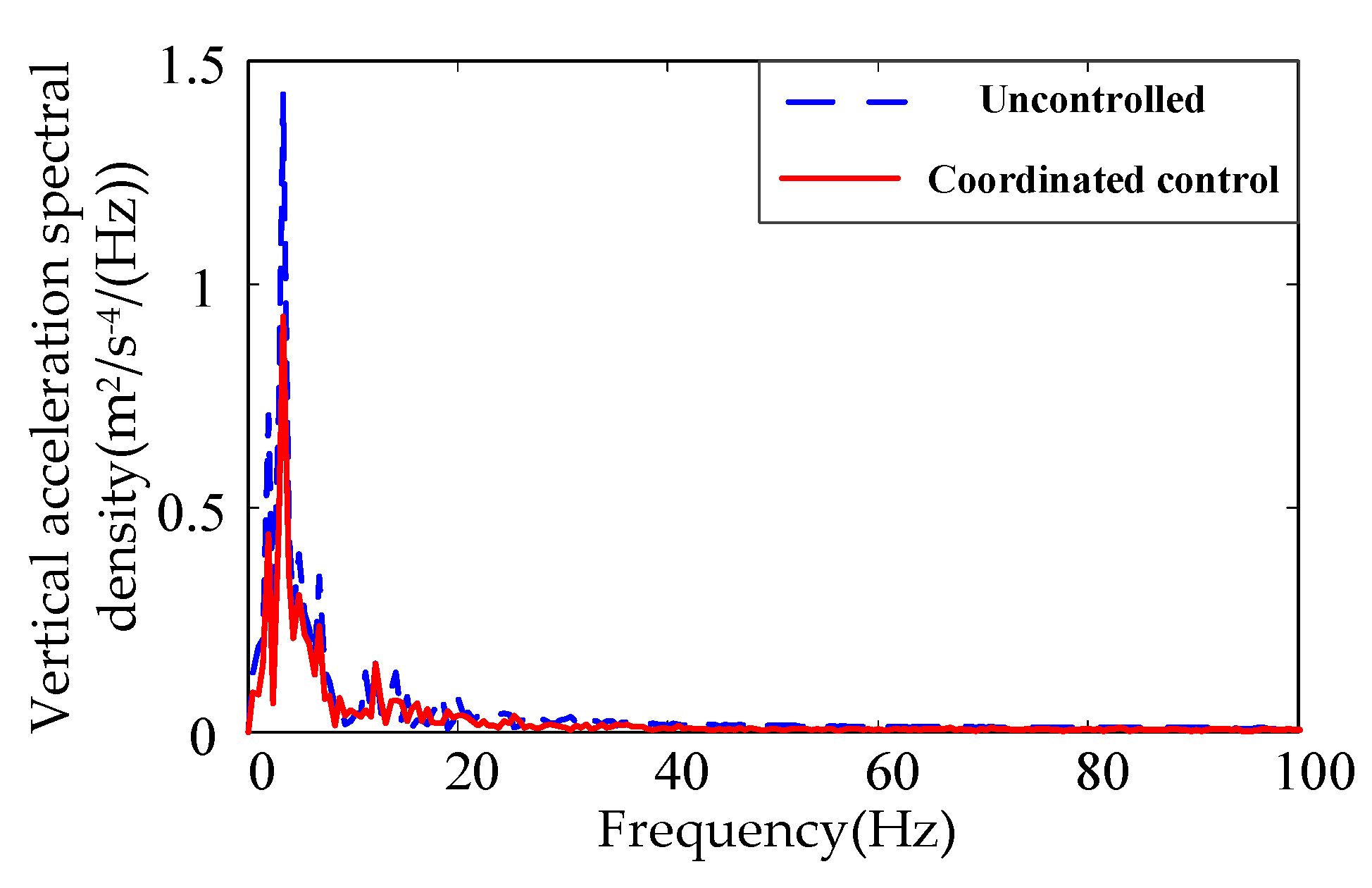
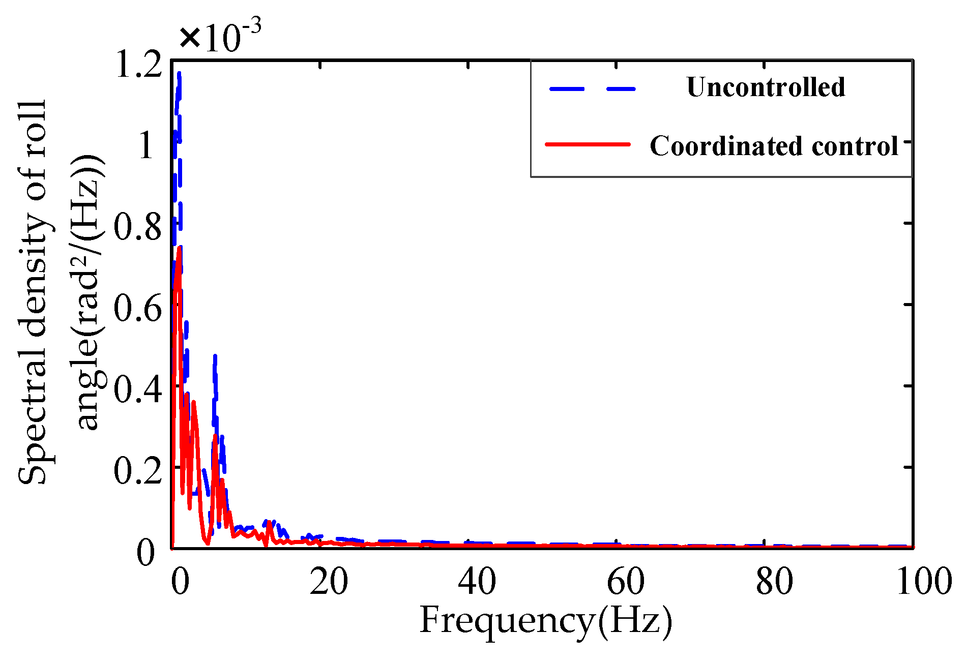
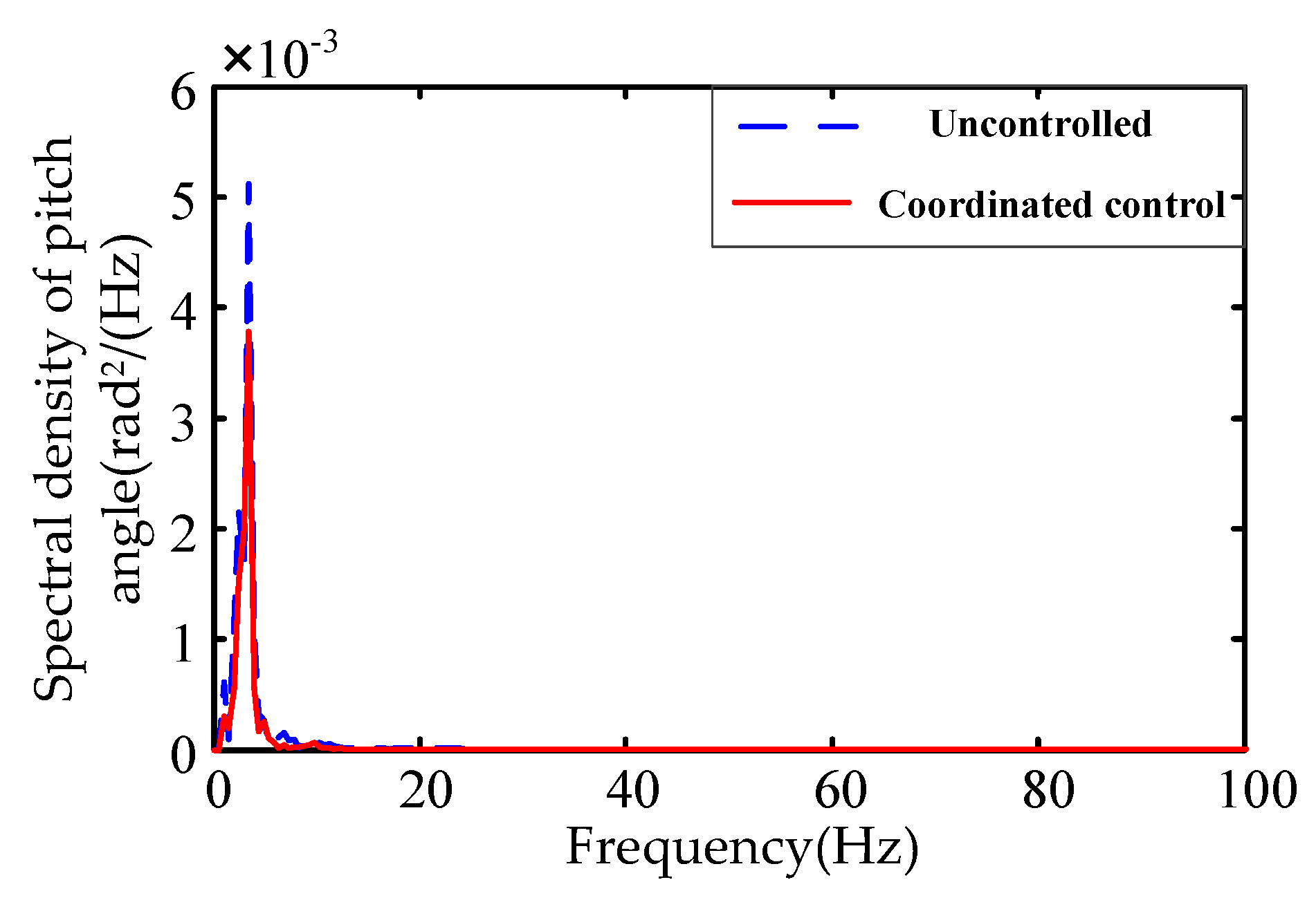
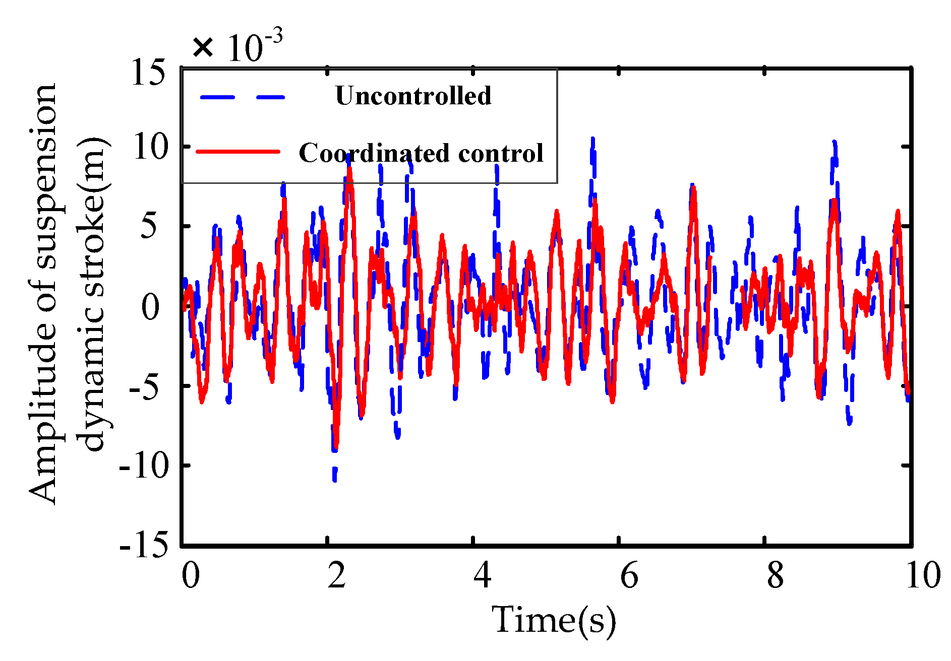
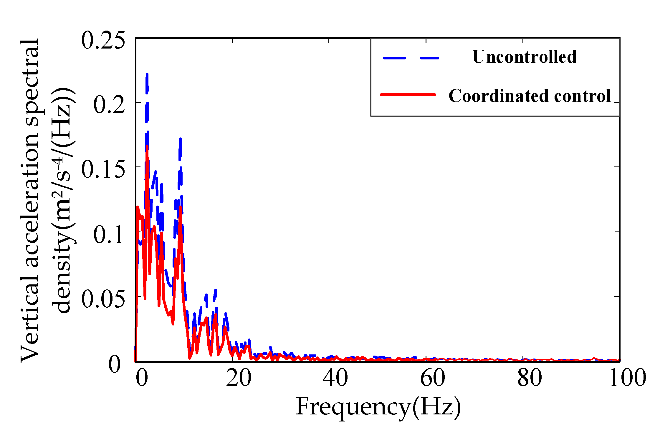
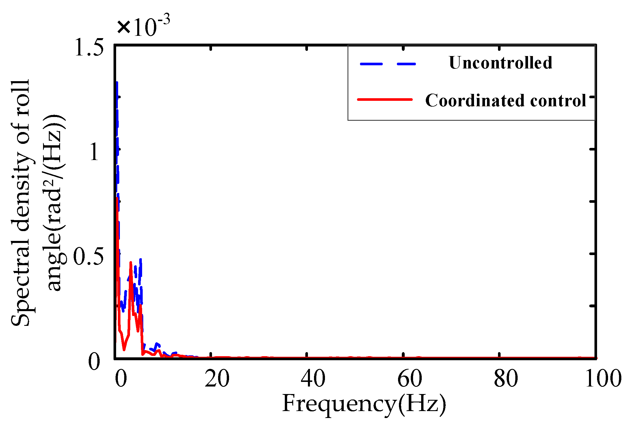
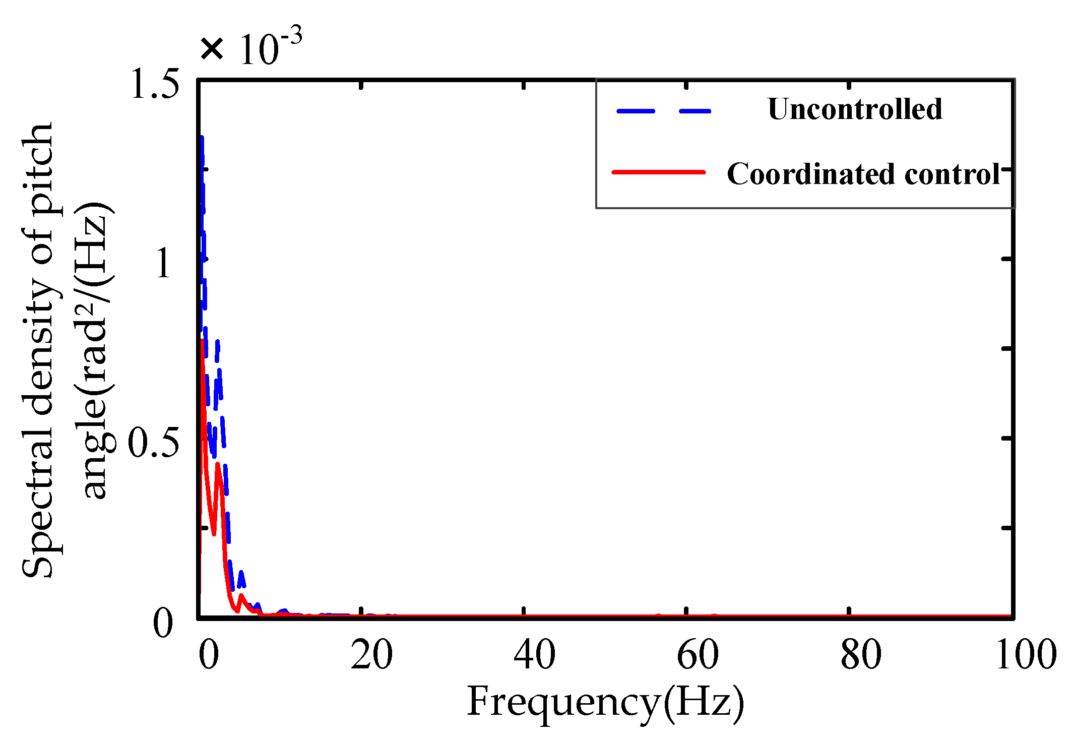
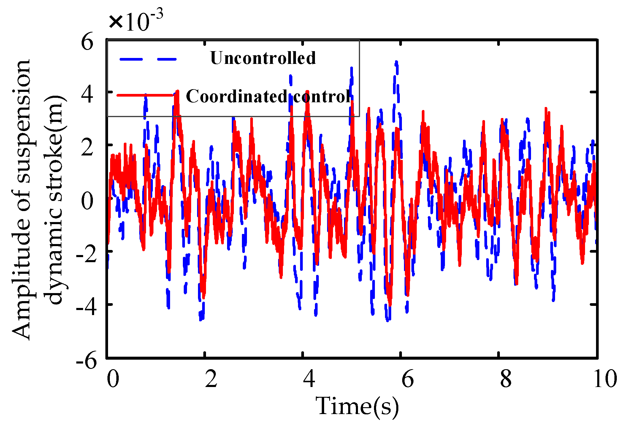
Compared with the uncontrolled traditional air suspension, the spectral density of vertical acceleration and the spectral density of body roll angle decreased significantly in resonance frequency at low frequency, which can indicate that a great improvement in the comfort of the vehicle, as shown in Figure 16 and Figure 17. Figure 18 shows the peak power spectral density of pitch angle was almost unchanged because the acceleration time of vehicle was short and the time that the coordinated controller takes pitch angle as the main optimization objective was short. From Figure 19, it can be seen that the suspension dynamic stroke decreased obviously, which means that the probability of suspension hitting the limit block is reduced, the service life of suspension is extended, and the ride comfort of the vehicle is improved.
6. Verification of Bench Test
In view of the safety uncertainty and the limitation of the research conditions of the real vehicle test, the test was realized by setting up a test bench. There is no indirect transformation between the straight condition and the steering condition in a bench test, so the complex conditions were divided into a straight condition and a steady-state steering condition under standard-B road excitation. If the results of the tests under these two conditions are improved, the correctness of the simulation test can be indirectly proved. In this experiment, MTS320-035 four-post test rig was used to simulate the road input in the course of vehicle driving. Figure 20 is the structure of the test bench.
6.1. Experiments under the Straight Condition of Standard-B Road Excitations
The experimental conditions were as follows: the amplitude of sinusoidal input was 10 mm, and the frequency range was 0.5 to 8 Hz. Excitation signal of stone pavement provided by the controller of MTS four-post test rig was used on a random road. The phase angle between front wheels and rear wheels was 180°, and the speed was set to 60 km/h. The sprung mass of test bench was 1050 kg under the no-load condition, and the sprung mass with a dummy model became 1290 kg.
Figure 21, Figure 22, Figure 23 and Figure 24 show the comparison of vehicle vertical acceleration, the pitch angle, the roll angle, and suspension dynamic stroke. After adopting the IASS with coordinated control, the root mean square (RMS) value of vertical acceleration, the RMS value of roll angle and the RMS value of the pitch angle were reduced. The improvement rate of vertical acceleration was 22.15%, and the improvement rate of roll angle was 8.34%. Meanwhile, the RMS of dynamic stroke was reduced, which shows that the control system can significantly improve the ride comfort of the vehicle body and restrain the pitching motion better. This coordinated system controls the dynamic stroke in a small range effectively and reduces the probability of the number of collisions between suspensions and limit blocks. Table 3 shows the simulation results of the RMS value of each index under a straight condition of standard-B road excitation.
6.2. Experiments under the Steady-State Steering Condition of Standard-B Road Excitations
The steady-state steering condition under standard-B road excitation was adopted, and the speed was 40 km/h. The phase angle between front wheels and rear wheels was 180°. The steering function cannot be achieved due to MTS320-035 four-post test rig can only provide vertical incentives. Thus, the sand bags were unevenly placed on the bench, and the roll moment generated by the sprung mass was used to replace the roll moment in the actual steady-state steering process. The dynamic performance of IASS with coordinated control was compared with uncontrolled IASS.
Test results analysis: vehicle vertical acceleration, the pitch angle, the roll angle, and suspension dynamic stroke, as shown in Figure 25, Figure 26, Figure 27 and Figure 28, respectively. Under the same structural parameters and road excitation, the RMS of vertical acceleration, the RMS of roll angle, and the RMS of pitch angle all decreased after adopting the coordinated dynamic performance control system of the IASS. The RMS improvement rate of vertical acceleration reached 12.24% and significantly decreased the RMS of acceleration of the dynamic stroke was observed in IASS with coordinated control compared with uncontrolled IASS. The above experiments showed that the control method can significantly improve the ride comfort of the vehicle body and restrain the pitching motion better under the steady-state steering conditions. Table 4 shows the RMS value of each index under the steady-state steering condition.
7. Conclusions
A new type of interconnected air suspension system with switchable interconnection modes and adjustable damping force was proposed in this paper, which combined an interconnected modes switching controller and dampers controlled by the differential game. Based on the comprehensive evaluation index value calculated in real-time during the simulation process, an interconnected modes switching controller was designed to keep the vehicle in the optimal interconnected mode under different working conditions. This innovation can provide a new idea for the research in the control method for interconnected modes of the IASS. Based on the optimal interconnection mode, the optimal distribution of the damping force of the adjustable damper was realized by establishing a differential game model of vehicle performance, which significantly improved the integrated dynamic performance of the IASS. The simulation results showed that the designed controller reduced the vertical acceleration by 19.64% and the roll angle by 33.92% in complex conditions, which effectively improved the ride comfort and handling stability. Based on the modified bench with IASS, the control performance of the system was verified. The vertical acceleration decreased by 18.32% and the dynamic stroke decreased by more than 10% under the straight condition; the vertical acceleration decreased by 12.24% and the roll angle decreased by 1.26% under the steering condition. The designed coordinated control can achieve the coordination of vehicle ride comfort and handling stability, which significantly improves the comprehensive dynamic performance of IASS, and lays a theoretical foundation for the further promotion of the interconnected air suspension system.
Author Contributions
L.S. and Y.L. conceived of and designed the method. G.G. and Y.L. performed the software simulation and analysis. Z.L. and H.J. performed the experiments and analyzed the experimental data. Y.L. wrote the paper with the help of L.S., G.G., Z.L., and H.J.
Funding
This work is financially supported by The National Natural Science Fund (No. 51575241, No. 51775245 and No. 51605197) and Natural Science Fund Project of Colleges in Jiangsu Province (No. BK20131255).
Conflicts of Interest
The authors declare no conflict of interest.
References
- Kim, H.; Lee, H. Height and Leveling Control of Automotive Air Suspension System Using Sliding Mode Approach. IEEE Trans. Veh. Technol. 2011, 60, 2027–2041. [Google Scholar]
- Eskandary, K.P.; Khajepour, A.; Wong, A. Analysis and optimization of air suspension system with independent height and stiffness tuning. Int. J. Automot. Technol. 2016, 17, 807–816. [Google Scholar] [CrossRef]
- Davis, L. Altering heavy vehicle air suspension dynamic forces by modifying air lines. Int. J. Heavy Veh. Syst. 2011, 18, 1–17. [Google Scholar] [CrossRef]
- Li, Z.X.; Cui, Z.; Xu, X. Experimental Study on the Dynamic Performance of Pneumatically Interlinked Air Suspension. Sci. Tech. Eng. 2014, 14, 82–86. [Google Scholar]
- Jiang, H.; Yang, Y.F.; Wang, Y.J. Experimental study on height control and energy consumption characteristics of closed-loop air circuit interconnected air suspension system. J. Cent. South Univ. 2017, 48, 270–276. [Google Scholar]
- Chen, Y.K.; Huang, S.; Davis, L. Optimization of Geometric Parameters of Longitudinal-Connected Air Suspension Based on a Double-Loop Multi-Objective Particle Swarm Optimization Algorithm. Appl. Sci. 2018, 8, 1454. [Google Scholar] [CrossRef]
- Eskandary, P.K. Interconnected Air Suspensions with Independent Height and Stiffness Tuning. Master’s Thesis, University of Waterloo, Waterloo, ON, Canada, 2014. [Google Scholar]
- Range Rover. Purchasing a Range Rover Mark III/L322: Details and Assistance for Purchasing a Third Generation Range Rover [EB/OL]. Available online: http://www.rangerovers.net/researchl322.html (accessed on 7 April 2013).
- Jiang, H.B.; Ye, S.C.; Du, Y. Study on basic features of gas-liquid mechanical coupling suspension strut. Int. J. Veh. Des. 2016, 72, 88–105. [Google Scholar] [CrossRef]
- Zulkarnain, N.; Imaduddin, F.; Zamzuri, H. Application of an Active Anti-roll bar system for enhancing vehicle ride and handling. In Proceedings of the IEEE Colloquium on Humanities, Science and Engineering Research (CHUSER), Kota Kinabalu, Malaysia, 3–4 December 2012. [Google Scholar]
- Wang, D.Z.; Zhao, D.X.; Gong, M.D. Research on Robust Model Predictive Control for Electro-hydraulic Servo Active Suspension Systems. IEEE Access 2017, 6, 3231–3240. [Google Scholar] [CrossRef]
- Ahmadian, M. Magneto-rheological suspensions for improving ground vehicle’s ride comfort, stability, and handling. Veh. Syst. Dyn. 2017, 55, 1618–1642. [Google Scholar] [CrossRef]
- Wang, R.C.; Yu, F.; Shao, K. Design and Performance Analysis of Electromagnetic Suspension Based on In-wheel Motor Car. Trans. Chin. Soc. Agric. Mach. 2018, 49, 382–389. [Google Scholar]
- Zhao, Y.; Wang, L.; Yang, X. Study on the ride performance of a semi-active air suspension vehicle under complex models based on co-simulation. SAE Tech. Pap. 2015, 1, 615–624. [Google Scholar]
- Zeng, L.M. Coordinated Control of Vehicle Ride Comfort and Handing Stability Based on Active Suspension. Master’s Thesis, Hunan University, Changsha, China, 2017. [Google Scholar]
- Chiang, H.H.; Lee, L.W. Optimized Virtual Model Reference Control for Ride and Handling Performance Oriented Semiactive Suspension Systems. IEEE Trans. Veh. Technol. 2015, 68, 1679–1690. [Google Scholar]
- Chen, S.; Zong, C.F.; Liu, L.G. Co-simulation on the Coordinated Control of Ride Comfort and Handling Stability of Vehicles with Active Suspension. Automot. Eng. 2012, 34, 791–797. [Google Scholar]
- Bharali, J.; Buragohain, M. Design and performance analysis of Fuzzy LQR, Fuzzy PID and LQR controller for active suspension system using 3 Degree of Freedom quarter car model. In Proceedings of the 1st IEEE International Conference on Power Electronics, Intelligent Control, and Energy Systems (ICPEICES), Delhi, India, 4–6 July 2016. [Google Scholar]
- Chen, W.W.; Zhu, H. Coordinated Control of Vehicle Ride Comfort and Handling Stability Based on modes Identification. CJME 2011, 47, 121–129. [Google Scholar]
- Mohsenian-Rad, A.; Wong, V.W.S.; Jatskevich, J. Autonomous Demand-Side Management Based on Game-Theoretic Energy Consumption Scheduling for the Future Smart Grid. IEEE Trans. Smart Grid 2010, 1, 320–331. [Google Scholar]
- Juan, P.; Santiago, Z. Wireless Networks under a Backoff Attack: A Game Theoretical Perspective. Sensors 2018, 18, 404–422. [Google Scholar]
- Na, X.; Cole, D.J. Linear quadratic game and non-cooperative predictive methods for potential application to modelling driver-AFS interactive steering control. Veh. Syst. Dyn. 2013, 51, 165–198. [Google Scholar] [CrossRef]
- Segal, A.; Miloh, T. A new 3-D pursuit-evasion differential game between two bank-to-turn airborne vehicles. Optim. Control Appl. Meth. 2015, 20, 223–234. [Google Scholar]
- Wang, H.W.; Yu, X.C.; Song, H.B. A Global Optimal Path Planning and Controller Design Algorithm for Intelligent Vehicles. Mob. Netw. Appl. 2016, 23, 1165–1178. [Google Scholar] [CrossRef]
- Wolf-Monheim, M.; Schumacher, M.; Frantzen, F. Interconnected air suspension systems: The influence on ride comfort in testing and simulation. Atzautotechnology 2009, 9, 58–61. [Google Scholar]
- Li, F.; Fu, M.H.; Huang, Y.H. Analysis of Dynamic Characteristic Parameter of Air Spring. J. Southwest Jiaotong Univ. 2003, 38, 276–281. [Google Scholar]
- Li, Z.X.; Li, M.; Guo, J.W. Novel Test Platform and Performance Test Study on Air Spring with Auxiliary Chamber. CJME 2012, 48, 98–102. [Google Scholar]
- Li, L.Y. The Numerical Simulation Researches of Comprehensive Evaluation Methods’ Performances. Master’s Thesis, Northeastern University, Shenyang, China, 2010. [Google Scholar]
- Engwerda, J.C.; Salmah. Feedback Nash Equilibria for Linear Quadratic Descriptor Differential Games. Automatica 2012, 48, 625–631. [Google Scholar]
- Reddy, P.; Zaccour, G. Feedback Nash Equilibria in Linear-Quadratic Difference Games with Constraints. IEEE Trans. Autom. Control 2017, 62, 590–604. [Google Scholar]
Figure 1.
The structure and working principle of the interconnected air suspension system (IASS).

Figure 2.
7 degrees of freedom model of vehicle.

Figure 3.
Control system of the IASS for coordinating dynamic characteristics.

Figure 4.
Ride comfort index Ja under the straight condition.

Figure 5.
Handling stability index Jb under the straight condition.

Figure 6.
Ride comfort index Ja under the steering condition.

Figure 7.
Handling stability index Jb under the steering condition.

Figure 8.
Root mean square (RMS) value of roll angle under the straight condition.

Figure 9.
RMS value of pitch angle under the straight condition.

Figure 10.
RMS value of roll angle under the steering condition.

Figure 11.
RMS value of pitch angle under the steering condition.

Figure 12.
Vehicle model with IASS in veDYNA.

Figure 13.
Vehicle speed.

Figure 14.
Vehicle steering wheel angle.

Figure 15.
Vehicle driving path.

Figure 16.
Response of vehicle vertical acceleration.

Figure 17.
Response of vehicle roll angle.

Figure 18.
Response of vehicle pitch angle.

Figure 19.
Response of dynamic stroke for front left suspension.

Figure 20.
Structure of the test bench.

Figure 21.
Vehicle vertical acceleration under the straight condition.

Figure 22.
Vehicle roll angle under the straight condition.

Figure 23.
Vehicle pitch angle under the straight condition.

Figure 24.
Dynamic stroke for front left suspension under the straight condition.

Figure 25.
Vehicle vertical acceleration under the steering condition.

Figure 26.
Vehicle roll angle under the steering condition.

Figure 27.
Vehicle pitch angle under the steering condition.

Figure 28.
Dynamic stroke for front left suspension under the steering condition.


Table 1.
Control strategy of air suspension interconnection modes.
| Vehicle Driving Mod | Major Contradictory Judgment | Secondary Contradictory Judgment | Interconnection Mode |
|---|---|---|---|
| Straight condition (|δ| < 10°) | Ja < 1.23, Jb ≥ 0.89 | θb ≥ 1.12 × 10⁻², ϕb ≥ 2 × 10⁻³ | Non-interconnected |
| θb ≥ 1.12 × 10⁻², ϕb < 2 × 10⁻³ | Lateral interconnection | ||
| θb < 1.12 × 10⁻², ϕb ≥ 2 × 10⁻³ | Longitudinal interconnection | ||
| θb < 1.12 × 10⁻², ϕb < 2 × 10⁻³ | Four-corner interconnection | ||
| Other | Ja | Four-corner interconnection | |
| Steering running (|δ| ≥ 10°) | Ja ≥ 2.59, Jb ≥ 1.37 | θb < 9.3 × 10⁻³, ϕb < 1.65 × 10⁻² | Longitudinal interconnection |
| Ja ≥ 2.59, Jb < 1.37 | Ja | Longitudinal interconnection | |
| Ja < 2.59, Jb ≥ 1.37 | θb < 9.3 × 10⁻³, ϕb < 1.65 × 10⁻² | Longitudinal interconnection | |
| Ja < 2.59, Jb < 1.37 | θb < 9.3 × 10⁻³, ϕb < 1.65 × 10⁻² | Longitudinal interconnection | |
| Other | θb, ϕb | Non-interconnected |
Table 2.
Vehicle model parameters.
| Parameter | Value | Unit |
|---|---|---|
| Body quality | 2140 | kg |
| Unsprung mass | 200 | kg |
| Roll moment of inertia | 589 | kg∙m2 |
| Pitch moment of inertia | 3784 | kg∙m2 |
| Front wheel tread | 1.51 | m |
| Rear wheel tread | 1.51 | m |
| Distance from body centroid to front axle | 1.42 | m |
| Distance from body centroid to rear axle | 1.32 | m |
| Torsional stiffness of front lateral stabilizer | 2400 | N∙m |
| Torsional stiffness of rear lateral stabilizer | 1600 | N∙m |
| Damping coefficient of front shock absorber | 2800 | N∙s/m |
| Damping coefficient of rear shock absorber | 2800 | N∙s/m |
| Inside diameter of interconnected pipeline | 10 | mm |
| Length of lateral connecting pipelines | 1.7 | m |
| Length of longitudinal connecting pipelines | 2.57 | m |
| Tire stiffness | 250 | kN/m |
Table 3.
Test results of the root mean square (RMS) value of each index under the straight condition.
Table 3.
Test results of the root mean square (RMS) value of each index under the straight condition.
| RMS of Indicators | Uncontrolled Traditional Suspension | IASS with Coordinated Control | Improvement Rate |
|---|---|---|---|
| RMS of vertical acceleration (m/s2) | 1.2198 | 0.9963 | 18.32% |
| RMS of roll angle (rad) | 0.0013 | 0.0012 | 8.34% |
| RMS of pitch angle (rad) | 0.0109 | 0.0107 | 1.83% |
| Front left dynamic stroke (m) | 0.0490 | 0.0439 | 10.40% |
| Front right dynamic stroke (m) | 0.0494 | 0.0435 | 11.94% |
| Rear left dynamic stroke (m) | 0.0503 | 0.0446 | 11.33% |
| Rear right dynamic stroke (m) | 0.0507 | 0.0443 | 12.62% |
Table 4.
RMS value under the steady steering condition.
| RMS of Indicators | Non-Interconnected Suspension | IASS with Coordinated Control | Improvement Rate |
|---|---|---|---|
| RMS of vertical acceleration (m/s2) | 0.3839 | 0.3369 | 12.24% |
| RMS of roll angle (rad) | 0.0158 | 0.0156 | 1.26% |
| RMS of pitch angle (rad) | 0.0099 | 0.0096 | 3.03% |
| Left front dynamic stroke (m) | 0.0427 | 0.0412 | 3.51% |
| Right front dynamic stroke (m) | 0.0551 | 0.0548 | 5.44% |
| Left rear dynamic stroke (m) | 0.0469 | 0.0451 | 3.83% |
| Right rear dynamic stroke (m) | 0.0541 | 0.0528 | 2.41% |
© 2019 by the authors. Licensee MDPI, Basel, Switzerland. This article is an open access article distributed under the terms and conditions of the Creative Commons Attribution (CC BY) license (http://creativecommons.org/licenses/by/4.0/).
Share and Cite
MDPI and ACS Style
Sun, L.; Lin, Y.; Geng, G.; Li, Z.; Jiang, H. Research on Switching Interconnection Modes and Game Control of Interconnected Air Suspension. Energies 2019, 12, 3218. https://doi.org/10.3390/en12173218
AMA Style
Sun L, Lin Y, Geng G, Li Z, Jiang H. Research on Switching Interconnection Modes and Game Control of Interconnected Air Suspension. Energies. 2019; 12(17):3218. https://doi.org/10.3390/en12173218
Chicago/Turabian StyleSun, Liqin, Yong Lin, Guoqing Geng, Zhongxing Li, and Haobin Jiang. 2019. "Research on Switching Interconnection Modes and Game Control of Interconnected Air Suspension" Energies 12, no. 17: 3218. https://doi.org/10.3390/en12173218
Note that from the first issue of 2016, this journal uses article numbers instead of page numbers. See further details here.