Design and Potential Power Recovery of Two Types of Energy Harvesting Shock Absorbers


Industrial Engineering and Automotive, Nebrija University, Campus de la Dehesa de la Villa, Calle Pirineos, 55, 28040 Madrid, Spain
*
Author to whom correspondence should be addressed.
Energies 2019, 12(24), 4710; https://doi.org/10.3390/en12244710
Submission received: 14 November 2019
/
Revised: 3 December 2019
/
Accepted: 5 December 2019
/
Published: 10 December 2019
(This article belongs to the Special Issue Electronic Systems and Energy Harvesting Methods for Automation, Mechatronics and Automotive)
Abstract
:Numerous authors have studied Energy Harvesting Shock Absorbers (EHSA) over the last decade, proposing different designs with diverse geometries, parameters, and components. This article analyzes the energy recovery potential of two types of rotational EHSA, those that use ball-screw and those based on cable transmission. This paper presents the design, manufacturing and mathematical modeling of both options as well as the estimation of the potential power recovery with both technologies. Two types of vehicles are used as references, each one with the characteristic curves of their shock absorbers. Results are presented for different vehicle speeds and road types. Finally, some qualitative characteristics of both EHSAs are detailed to be taken into consideration for their possible use in vehicle suspension.
1. Introduction
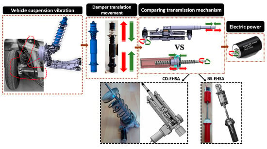
The recovery of energy from different areas of the vehicle is a topic that has attracted the attention of many researchers in recent years, resulting in a large number of publications. A considerable number of references propose harvesting energy from: the heat given off by the exhaust pipes [1,2,3,4,5], the absorption of the kinetic energy in the brakes [6,7,8,9], the deformation of the tires [10,11], the vibrations of the engine [12,13], the seats [14], and also the suspension system of the vehicle [15].
The energy recovery in the suspension system, more specifically in the shock absorber, is carried out with Energy Harvesting Shock Absorbers (EHSA). Abdelkareem et al. [16] and Zhang et al. [17] made a review of all the EHSA technology that have been presented up to the present time. These systems usually work generating a magnetic field variation around a winding, resulting in a current and an electrical voltage. This variation of magnetic field can be generated in two ways—linearly and/or rotationally. Tang et al. [18] and Singh et al. [19] have proposed linear electromagnetic dampers. In the first reference, the authors obtain a power of 26–33 W at an excitation speed (piston velocity of the damper) of 0.25 m/s, while for the second the power is 160 W at a speed of 0.1 m/s. On the other hand, Zhang et al. [20] presented a system in which they duplicate the relative speed between the magnetic field and the conductor, multipliying the generated power by four.
There are several types of rotational electromagnetic dampers. As the movement in the vehicle suspensions is translational, the generation of a rotationally variable magnetic field requires a mechanism that converts translation into a rotation. These are well-known systems: rack-pinion [21,22,23], hydraulic [24,25,26,27,28,29], ball-screw [30,31,32,33], and some more exotic such as the “Linkage mechanism” [34], “Two-Leg motion” [35], or using flywheel drive [36]. All these systems have their own equivalent inertias, backlashes, and frictions affecting the dynamic behavior of the shock absorber and, therefore, the vehicle.
One of the main difficulties when analyzing the EHSAs found in the literature is the lack of a common strategy to compare the different systems. Most authors present original designs but focus their attention on achieving different objectives: generate the maximum amount of power, have a certain damping coefficient, have a damping force or obtain the maximum efficiency in the system, etc.
In this article, two types of rotational EHSA are compared under a common framework. The EHSAs that use the ball-screw transmission system, known as the Ball-Screw Energy Harvesting Shock Absorber (BS-EHSA), and the EHSAs that use the cable transmission system, also known as the Cable-Dynamic Energy Harvesting Shock Absorber (CD-EHSA). The main objective of this work is to compare quantitatively and qualitatively an innovative EHSA design (CD-EHSA) with one found in the literature (BS-EHSA). In addition, to provide reliable data of the potential that both systems have in the recovery of energy from the suspension of vehicles.
The main contributions of this work concentrate on four aspects:
- The design, manufacture, and mathematical modeling of the systems: BS-EHSA and CD-EHSA.
- The results, experimental and simulation of the electrical power that is generated with both technologies for different conditions. Taking as reference the characteristic curves of the damper of a Renault Twizy and Ford Focus.
- The results shown in this work, both for the BS-EHSA and for the CD-EHSA, make it possible to compare each other because they share the same initial conditions.
- Qualitative analysis of both technologies for their future application in vehicle suspension systems.
This article is divided into seven sections. The first being the introduction, the second section describes under which common framework the prototypes have been manufactured. The third section shows the design, the prototype, and mathematical model of the BS-EHSA, while the fourth section does the same for the CD-EHSA. The fifth section details the conditions that have been established to evaluate the potential of both the BS-EHSA and CD-EHSA in energy recovery in the vehicle’s damping. In the sixth section the results are presented, together with a qualitative analysis of the characteristics of both systems. In the last section, some conclusions of the work are presented.
2. Framework to Analyze the Performance of the BS-EHSA and CD-EHSA
The rotational EHSAs contain a characteristic design parameter: feed rate per revolution (FRR), normally given in mm/rev. This parameter varies in the literature [21,33,37] between 4–6 mm/rev. In the prototypes presented below, it has been decided to choose the value of 5 mm/rev. Therefore, both systems, the BS-EHSA and CD-EHSA, are designed with the same feed value.
The same generator is installed in both prototypes (Maxon 218010), which is also the one used by Li et al. [37]. Table 1 shows the specifications of this generator.
This way with the same generator and the same translation into a rotation parameter, the difference that will exist between the BS-EHSA and the CD-EHSA will only be the translation into a rotation transmission system, which implies differences in equivalent inertia, backlash, and internal friction. This applies to Section 3 and Section 4, where both EHSAs share the same design parameters. However, in Section 5 and Section 6, the design parameters are changed at this time with the intention to match the characteristic curves of the dampers of a Renault Twizy and a Ford Focus.
For the mathematical modeling of both systems, the equivalent mechanical model presented in Figure 1 will be used. This consists of deriving from the equations of the dynamics of each system a coefficient of: equivalent mass , also known as inerter [38], an equivalent damping coefficient , and an equivalent stiffness coefficient , as proposed by Bowen et al. [15], as in Equation (1).
3. Ball-Screw Energy Harvesting Shock Absorber (BS-EHSA)
3.1. Design Principle and Prototype
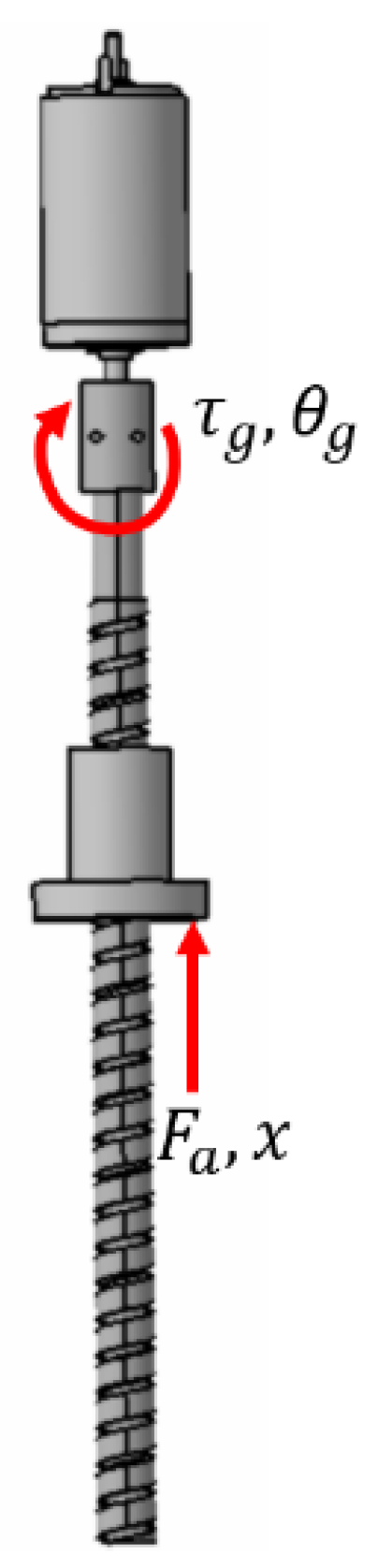
The Ball-Screw Energy Harvesting Shock Absorbers (BS-EHSA) as the name implies, uses a ball-screw transmission system to go from translation into rotation. Figure 2 shows an example of this type of shock absorber, which is composed of a nut, a screw, and a coupled generator. Table 2 specifies the design parameters of this type of damper.
3.2. Mathematical Model
For the derivation of the equivalent mechanical model, the equations of the dynamics of the system of Figure 3 are used:
Equation (2) represents the ball-screw energy balance of the generator, where is the ball screw efficiency, is the damping force, x is the linear displacement, is the torque over the screw, and represent the rotation of the screw and the generator:
Equation (3) represents the dynamic behavior of the generator, where is the rotational inertia, is the rotational damping, and represents the rotational stiffness of the generator:
Equation (4) accounts for the relationships among rotational and linear displacements.
These equations were previously derived by Li et al. [37]. Operating with the equations, their equivalent mechanical model coefficients (1) are:
3.3. Comparison of Simulations and Experiments
To simulate the dynamics of the BS-EHSA, the Simscape/Mathworks® program and the above are used. Armstrong et al. [39] introduced a friction model for all the moving parts and it was used here.
Figure 4 shows some of the simulations and experimental results, which show that the computational model is able to reproduce the force and the voltage results obtained in the experimental setup.
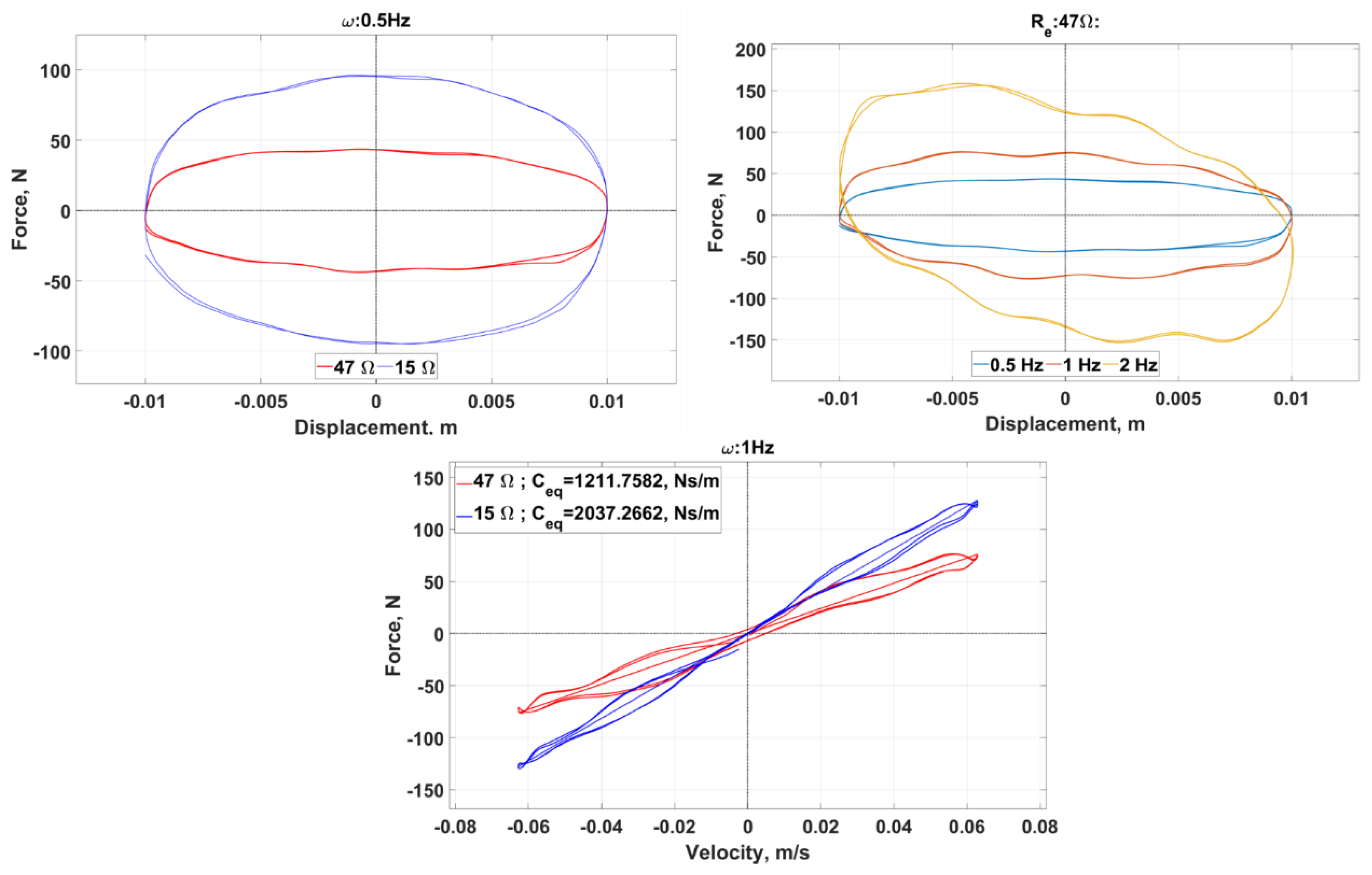
Figure 5 shows the test bench used for the BS-EHSA prototype (an MTS 835 machine). The tests were run between 0.5–3 Hz using different load electrical resistances (15, 47, 62, 94, and 109 Ω). The acquisition system is composed of a CompactRio NI cDaq-9178 module and a NI-9234 module. The results of the experimental tests can be seen in Figure 6. The graphs show that, as indicated by the equations, when the excitation frequency increases or when the external load decreases, the energy recovered by the BS-EHSA increases. Additionally, it can be seen that the damping coefficient will depend on the resistance that is connected to the generator.
4. Cable-Dynamics Energy Harvesting Shock Absorber (CD-EHSA)
4.1. Design Principle and Prototype
The Cable-Dynamic Energy Harvesting Shock Absorbers (CD-EHSAs) use a steel cable and a pair of pulleys as the main element for the translational into rotational conversion. Figure 7 shows an example of such a shock absorber. The translation movement of the suspension is transferred through a piston (1) to a sliding part running on linear guides (2). The sliding part has two preloaded cables (3) that displace it. The cable is connected in one end to a driven pulley (4) and to the other end to a generator pulley (5), which is connected to another larger pulley (6). This one is connected through a band to a smaller pulley (7) that doubles the rotational speed. The smaller pulley is rigidly assembled to a multiplier (8) connected to an electric generator (9). Table 3 specifies the design parameters of this type of shock absorber.
4.2. Mathematical Model
For the derivation of the equivalent mechanical model, the equations of the system dynamics of Figure 8 are used as follows:
Relationship between input force and tensors:
Balance of energy in generator pulley:
Balance of forces in each of the two tensors:
Preload in the cable:
Balance of moments in the driven pulley:
Relationships between the angular velocity of the pulleys and the displacements:
Balance of energy in transmission pulley 1 and 2:
Balance of energy in the multiplier:
Relationships between the angular displacements, velocities, and radiuses of the pulleys:
Dynamic behavior of the generator:
Equations (8)–(15) refer to the transmission of the movement from the cable to the pulleys, and the rest relate to the dynamic behavior of the transmission pulleys, the multiplier, and the generator. Operating with the equations, the equivalent mechanical model coefficients (1) are obtained:
4.3. Comparison of Simulations and Experiments
The Simscape/Mathworks® program is also used to simulate the dynamics of the CD-EHSA using the above equations and the same friction model that is in the BS-EHSA case. Experimental results fitting computational ones are shown in Figure 9.
Experimental tests were also run in the MTS 835 machine (Figure 10). The results are presented in Figure 10. The same excitation frequencies and loads as in the BS-ESHA case were used. The tests were carried out for the same excitation frequencies and resistance load as in the case of the BS-EHSA. Obtained for each were the damping force values and the generator voltage. Figure 11 shows, as for the BS-EHSA, that the behavior of the CD-EHSA is affected by changing both the excitation frequency and the external load that is connected to the generator.
5. Numerical Simulation using BS-EHSA and CD-EHSA
In Section 3 and Section 4, both EHSAs share the same feed rate per revolution (FRR) parameter and generator. However, in the simulation presented in this section and in Section 6, both parameters are changed (FRR and generator) in order to match the characteristic curves of the dampers of a Renault Twizy and a Ford Focus.
5.1. Vehicle Parameters and Modelling
This section details the boundary conditions that have been established to analyze the potential of both the BS-ESHA and the CD-EHSA for energy recovery in the vehicle suspension. For this, a model of a complete car with 7 degrees of freedom has been implemented, as shown in Figure 12 (right), the equations of both EHSAs are used to represent the dampers. The data are taken from two types of vehicles: a single-seater (Renault Twizy 45) and a 5-passenger car (Ford Focus), the table in Figure 12 (left) summarizes the main parameters.
5.2. Input Signals Generation
As an input signal for this model (), standardized road profiles according to ISO 8608 are used. For the two front wheels, a unit noise power signal (using the Simulink® program) is generated passing through a low-pass filter:
where is the roughness coefficient of the road in ; is a reference for the spatial frequency that is equal to 0.1. ; is the initial cut-off frequency that has a value of 0.0628 Hz and is the speed of the vehicle in . These data were obtained from the work of Abdelkareem et al. [40].
For the generation of the signal of the rear wheels, the method proposed by Ren et al. [41] is used. It allows a delay of the signal of the front wheels depending on the speed and length of the vehicle. This method consists of multiplying the signal of the front wheels by the transfer function:
where , is the distance between the front and rear wheel. In Figure 13 you can see the logarithmic graph of the PSD of the three types of road, both for the right and left wheels. The graphs show that the signals generated as input to the complete car system have the same theoretical slope as stipulated by ISO 8608. In the same figure, an example of a road profile is shown, driving at 100 km/h in a class C profile (Table 4).
5.3. EHSA Design
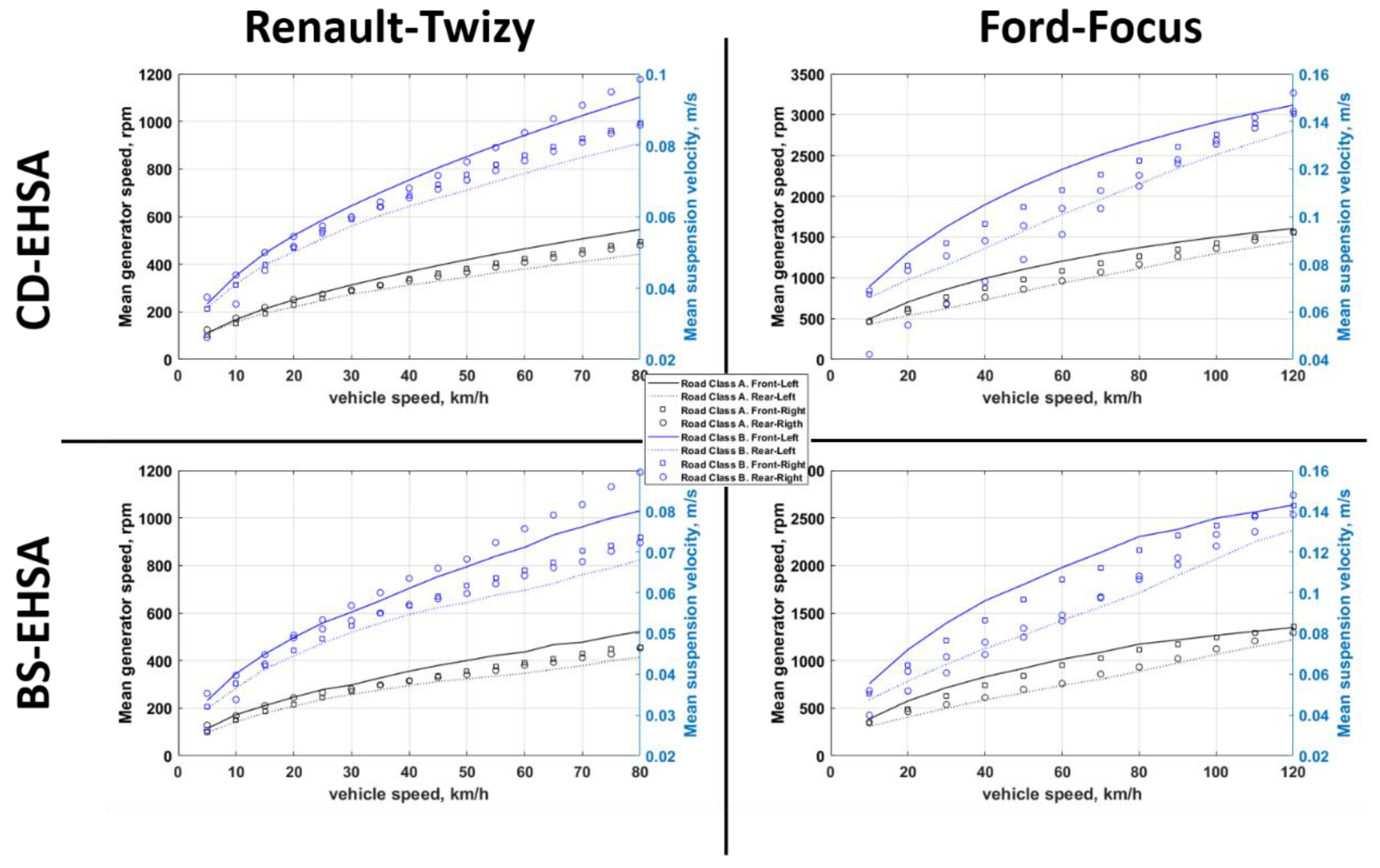
For the design of both EHSA, the force-speed curves of the dampers of a Renault Twizy and a Ford Focus are used, as can be seen in Figure 14. Both EHSAs have been designed so that they have the same damping value at low speeds. In the case of the Ford-Focus, it is 0.15 m/s and in the case of the Renault Twizy it is m/s. Figure 15 shows the average speeds we will have between the ends of the suspension driving on road types A and B (Table 4). Their values are within the range established as low speeds.
In order to obtain a different damping in compression and extension movements in the EHSA, the diode system proposed by Zhongjie et al. [37] is used, in this way different values of electrical resistance can be used depending on the direction of rotation of the generator.
The three most important parameters in the design of the rotational EHSA are: the feed rate per revolution (FRR) (mm/rev), the electromagnetic constant of the generator (rpm/V), and the electrical resistance connected to the generator (Ω). Both EHSAs require the same damping characteristics as the dampers already installed in both vehicles, therefore the design parameters presented in Table 5 have been chosen. The tables illustrate that for the Renault Twizy the Maxon 218,010 (Table 1) is used and for the Ford Focus, the Maxon 136,210 is used (Table 6). The limitations of the generators are in their maximum allowed speed and in their maximum current. From Figure 15, it can be seen that none of the generators, either using the BS-EHSA and/or the CD-EHSA in the four dampers, exceeds the permitted speed limit (12,000 rpm). The same applies to the induced current (Figure 16). The average current circulating inside the generator is kept below its maximum values all the time.
6. Results and Discussion
With the conditions described in the previous section, Figure 17 and Figure 18 show an estimation of the average power that can be generated with both EHSAs in the Renault Twizy and/or the Ford Focus. From the graphs, it can be seen that the power level increases with the speed of the vehicle and the roughness of the pavement.
Using the same approach as Múčka et al. [42], it can be deduced that the power that would be generated circulating at 120 km/h with the Ford Focus in the case of German roads () would be between 350–500 W, for Chinese roads () it would increase to 400–700 W, and for roads in Eastern Europe () it would be between 700–1200 W. Keep in mind that in all these results, the vehicle is driving in a straight line at a constant speed. Neither the curves, nor the cant on the roads, nor the accelerations or decelerations of the vehicle are taken into account, all these conditions would only increase the power generated by the EHSA.
With respect to the difference in power generation, 80–110% more can be generated using the CD-EHSA system compared to the BS-EHSA. One of the main causes explaining why the CD-EHSA system allows a greater power generation compared to the BS-EHSA is that internal inertia is much lower. The electrical power obtained from a generator is proportional to the square of the current flowing through its coils. If we look at Figure 16, we can see that the average current flowing through the CD-EHSA is higher than the BS-EHSA. This is because there is a greater force for the electromagnetic torque of the generator when the inertial force is lower.
Below (Table 7) are some advantages and disadvantages in the use of the CD-EHSA or the BS-EHSA as a damping system in the vehicle.
7. Conclusions
This article addresses two types of rotational EHSA. The EHSAs that use the ball-screw transmission (BS-EHSA) and the EHSAs that use the cable transmission (CD-EHSA). For both systems, their mathematical model has been presented as well as a prototype with their respective experimental tests.
Once the simulation results are compared with the experimental tests, simulations were carried out to obtain the energy recovery potential that both technologies generate under different boundary conditions. The characteristic curves of the shock absorbers of a Renault Twizy and a Ford Focus were used. As an example, an estimate of power generation between 500–1000 W is obtained on an old pavement road (class C road) with a 5-passenger car at a speed of 120 km/h. The results also show that the CD-EHSA system can generate between 80–110% more power than with the BS-EHSA.
The EHSAs are technologies whose final aim is replacing conventional shock absorbers that are at present used on most, if not all, vehicles. For this reason, they must be able to provide the same dynamic behavior than conventional shock absorbers, but also have the same durability and provide the same comfort to the passengers. This paper gives some qualitative data on the BS-EHSA and CD-EHSA technologies that can be used in the development of energy recovery technologies in the suspension. Much has to be done still on the durability aspects that are directly related to the design and the selection of components, which has a direct implication on cost.
The results shown in this article are only theoretical. However, the frictions that may exist in the BS-EHSA and the CD-EHSA have been taken into account in the computational models. In addition, the power estimations summarized in this paper consider that the vehicle is traveling on a straight road at different speeds and road surface quality, and not taking into account other events in the vehicle suspension that exist that can increase the amount of harvested energy, such as the passage through curves, accelerations, and braking, etc.
Future works will include the development of functional prototypes to be installed in real vehicles and the validations of the concepts in real road conditions.
As a final general comment, the energy recovered in EHSAs has the clear advantage of being able to harvest energy that would otherwise be lost in the form of heat. The introduction of these systems in real vehicles must still overcome some technical difficulties, such as their reduction in weight and price. At the same time, a dynamic behavior similar to that of the shock absorbers they replace, including the comfort perceived by the passengers, must be ensured. Therefore, further research is necessary to make EHSA technically and economically viable.
Author Contributions
Resources and writing: L.B.; supervision: J.V.; review and editing: J.V. and J.L.O.
Funding
This research was funded by Comunidad de Madrid, grant number SEGVAUTO 4.0-CM-P2018EEMT-4362 and by the Agencia Estatal de Investigación RETOS 2018-RTI2018-095923-B-C22.
Acknowledgments
The authors wish to thank the support of “Cátedra de Recuperación de energía en el transporte de superficie” by Banco Santander.
Conflicts of Interest
The authors declare no conflict of interest.
References
- Orr, B.; Akbarzadeh, A.; Mochizuki, M.; Singh, R. A review of car waste heat recovery systems utilising thermoelectric generators and heat pipes. Appl. Therm. Eng. 2016, 101, 490–495. [Google Scholar] [CrossRef]
- Liu, X.; Li, C.; Deng, Y.D.; Su, C.Q. An energy-harvesting system using thermoelectric power generation for automotive application. Int. J. Electr. Power Energy Syst. 2015, 67, 510–516. [Google Scholar] [CrossRef]
- Kim, T.Y.; Negash, A.a.; Cho, G. Waste heat recovery of a diesel engine using a thermoelectric generator equipped with customized thermoelectric modules. Energy Convers. Manag. 2016, 124, 280–286. [Google Scholar] [CrossRef]
- Rahman, A.; Razzak, F.; Afroz, R.; Mohiuddin, A.K.M.; Hawlader, M.N.A. Power generation from waste of IC engines. Renew. Sustain. Energy Rev. 2015, 51, 382–395. [Google Scholar] [CrossRef]
- Saidur, R.; Rezaei, M.; Muzammil, W.K.; Hassan, M.H.; Paria, S.; Hasanuzzaman, M. Technologies to recover exhaust heat from internal combustion engines. Renew. Sustain. Energy Rev. 2012, 16, 5649–5659. [Google Scholar] [CrossRef]
- Lv, C.; Zhang, J.; Li, Y.; Yuan, Y. Mechanism analysis and evaluation methodology of regenerative braking contribution to energy efficiency improvement of electrified vehicles. Energy Convers. Manag. 2015, 92, 469–482. [Google Scholar] [CrossRef]
- Qiu, C.; Wang, G. New evaluation methodology of regenerative braking contribution to energy efficiency improvement of electric vehicles. Energy Convers. Manag. 2016, 119, 389–398. [Google Scholar] [CrossRef]
- Jin, L.; Chen, P.; Liu, Y. An Analysis of Regenerative Braking and Energy Saving for Electric Vehicle with In-Wheel Motors. Int. J. Control. Autom. 2014, 7, 219–230. [Google Scholar] [CrossRef]
- Clegg, S.J. A Review of Regenerative Braking Systems; University of Leeds: Leeds, UK, 1996; p. 24. [Google Scholar]
- Lee, J.; Choi, B. Development of a piezoelectric energy harvesting system for implementing wireless sensors on the tires. Energy Convers. Manag. 2014, 78, 32–38. [Google Scholar] [CrossRef]
- Zhu, B.; Han, J.; Zhao, J.; Deng, W. Practical design of an energy harvester considering wheel rotation for powering intelligent tire systems. J. Electron. Mater. 2017, 46, 2483–2493. [Google Scholar] [CrossRef]
- Decoupler, P.Z.T. Vibration energy harvesting from a hydraulic engine mount via PZT decoupler. In Proceedings of the ASME 2010 International Mechanical Engineering Congress & Exposition IMECE2010, Vancouver, BC, Canada , 12–18 November 2010. [Google Scholar]
- Mohareri, O.; Arzanpour, S. Energy harvesting from vibration of a hydraulic engine mount using a turbine. In Proceedings of the 2011 IEEE International Conference on Mechatronics, Istanbul, Turkey, 13–15 April 2011; pp. 1–6. [Google Scholar]
- Ning, D.; Sun, S.; Du, H.; Li, W.; Zhang, N. Vibration control of an energy regenerative seat suspension with variable external resistance. Mech. Syst. Signal Process. 2017, 106, 94–113. [Google Scholar] [CrossRef] [Green Version]
- Bowen, L.; Vinolas, J.; Olazagoitia, J.L. Methodology for comparing the functional performance of energy harvesting shock absorbers. Int. J. Appl. Electromagn. Mech. 2017, 55, 545–564. [Google Scholar] [CrossRef]
- Abdelkareem, M.A.A.; Xu, L.; Ali, M.K.A.; Elagouz, A.; Mi, J.; Guo, S.; Liu, Y.; Zuo, L. Vibration energy harvesting in automotive suspension system: A detailed review. Appl. Energy 2018, 229, 672–699. [Google Scholar] [CrossRef]
- Zhang, R.; Wang, X.; John, S. A comprehensive review of the techniques on regenerative shock absorber systems. Energies 2018, 11, 1167. [Google Scholar] [CrossRef] [Green Version]
- Tang, X.; Lin, T.; Zuo, L. Design and optimization of a tubular linear electromagnetic vibration energy harvester. IEEE/ASME Trans. Mechatron. 2014, 19, 615–622. [Google Scholar] [CrossRef]
- Singh, S.; Satpute, N.V. Design and analysis of energy-harvesting shock absorber with electromagnetic and fluid damping. J. Mech. Sci. Technol. 2015, 29, 1591–1605. [Google Scholar] [CrossRef]
- Zhang, R.; Wang, X.; Liu, Z. A novel regenerative shock absorber with a speed doubling mechanism and its Monte Carlo simulation. J. Sound Vib. 2018, 417, 260–276. [Google Scholar] [CrossRef]
- Zhang, Z.; Zhang, X.; Chen, W.; Rasim, Y.; Salman, W.; Pan, H.; Yuan, Y.; Wang, C. A high-efficiency energy regenerative shock absorber using supercapacitors for renewable energy applications in range extended electric vehicle. Appl. Energy 2016, 178, 177–188. [Google Scholar] [CrossRef]
- Zhang, X.; Pan, H.; Qi, L.; Zhang, Z.; Yuan, Y.; Liu, Y. A renewable energy harvesting system using a mechanical vibration rectifier (MVR) for railroads”. Appl. Energy 2017, 204, 1535–1543. [Google Scholar]
- Li, P.; Zuo, L. Influences of the electromagnetic regenerative dampers on the vehicle suspension performance. J. Automob. Eng. 2017, 231, 383–394. [Google Scholar] [CrossRef]
- Galluzzi, R.; Xu, Y.; Amati, N.; Tonoli, A. Optimized design and characterization of motor-pump unit for energy-regenerative shock absorbers. Appl. Energy 2017, 210, 16–27. [Google Scholar] [CrossRef]
- Zhang, Y.; Chen, H.; Guo, K.; Zhang, X.; Li, S.E. Electro-hydraulic damper for energy harvesting suspension: Modeling, prototyping and experimental validation. Appl. Energy 2017, 199, 1–12. [Google Scholar] [CrossRef]
- Guo, S.; Lin, X.; Liu, Y.; Zuo, L. Modeling and experiments of a hydraulic electromagnetic energy harvesting shock absorber. IEEE/ASME Trans. Mechatron. 2017, 22, 11. [Google Scholar] [CrossRef]
- Zou, J.; Guo, X.; Xu, L.; Tan, G.; Zhang, C.; Zhang, J. Design, modeling, and analysis of a novel hydraulic energy-regenerative shock absorber for vehicle suspension. Shock Vib. 2017, 2017, 1–12. [Google Scholar] [CrossRef]
- Peng, M.; Guo, X.; Zou, J.; Zhang, C.M. Simulation Study on Vehicle Road Performance with Hydraulic Electromagnetic Energy-Regenerative Shock Absorber Hydraulic Electromagnetic Energy-Regenerative; SAE International: Warrendale, PA, USA, 2016; p. 10. [Google Scholar]
- Wang, R.; Gu, F.; Cattley, R.; Ball, A.D. Modelling, testing and analysis of a regenerative hydraulic shock absorber system. Energies 2016, 9, 386. [Google Scholar] [CrossRef] [Green Version]
- Xie, L.; Li, J.; Li, X.; Huang, L.; Cai, S. Damping-tunable energy-harvesting vehicle damper with multiple controlled generators: Design, modeling and experiments. Mech. Syst. Signal Process. 2017, 99, 859–872. [Google Scholar] [CrossRef]
- Bowen, L.; Vinolas, J.; Olazagoitia, J.L. Banco de ensayo para validar el modelo computacional de un cuarto de coche con amortiguador recuperador de energía. Dyna 2017, 93, 82–95. [Google Scholar] [CrossRef]
- Xie, L.; Li, J.; Cai, S.; Li, X. Electromagnetic energy-harvesting damper with multiple independently controlled transducers: On-demand damping and optimal energy regeneration. IEEE/ASME Trans. Mechatron. 2017, 22, 2705–2713. [Google Scholar] [CrossRef]
- Liu, Y.; Xu, L.; Zuo, L. Design, Modeling, Lab and Field Tests of a Mechanical-motion-rectifier-based Energy harvester using a ball-screw mechanism. IEEE/ASME Trans. Mechatron. 2017, 22, 1933–1943. [Google Scholar] [CrossRef]
- Sabzehgar, R.; Maravandi, A.; Moallem, M. Energy regenerative suspension using an algebraic screw linkage mechanism. IEEE/ASME Trans. Mechatron. 2013, 19, 1251–1259. [Google Scholar] [CrossRef]
- Maravandi, A.; Moallem, M. Regenerative shock absorber using a two-leg motion conversion mechanism. IEEE/ASME Trans. Mechatron. 2015, 20, 2853–2861. [Google Scholar] [CrossRef]
- Zhang, R.; Wang, X.; al Shami, E.; John, S.; Zuo, L.; Wang, C.H. A novel indirect-drive regenerative shock absorber for energy harvesting and comparison with a conventional direct-drive regenerative shock absorber. Appl. Energy 2018, 229, 111–127. [Google Scholar] [CrossRef]
- Li, Z.; Zuo, L.; Luhrs, G.; Lin, L.; Qin, Y. Electromagnetic energy-harvesting shock absorbers: Design, modeling, and road tests. IEEE Trans. Veh. Technol. 2012, 62, 1065–1074. [Google Scholar] [CrossRef]
- Smith, M.C. Synthesis of mechanical networks: The inerter. IEEE Trans. Automat. Contr. 2002, 47, 1648–1662. [Google Scholar] [CrossRef] [Green Version]
- Armstrong, B.; de Wit, C.C. Friction modeling and compensation. In the Control Handbook; CRC Press: Boca Raton, FL, USA, 1995. [Google Scholar]
- Abdelkareem, M.A.A.; Xu, L.; Guo, X.; Ali, M.K.A.; Elagouz, A.; Hassan, M.A.; Essa, F.A.; Zou, J. Energy harvesting sensitivity analysis and assessment of the potential power and full car dynamics for different road modes. Mech. Syst. Signal Process. 2018, 110, 307–332. [Google Scholar] [CrossRef]
- Ren, H.; Chen, S.; Wu, Z. Model of excitation of random road profile in time domain for a vehicle with four wheels. In Proceedings of the 2011 International Conference on Mechatronic Science, Electric Engineering and Computer (MEC), Jilin, China, 19–22 August 2011; pp. 2332–2335. [Google Scholar]
- Múčka, P. Simulated road profiles according to ISO 8608 in vibration analysis. J. Test. Eval. 2017, 46, 405–418. [Google Scholar] [CrossRef]
Figure 1.
Equivalent mechanical system configuration for the Energy Harvesting Shock Absorbers (EHSA).
Figure 1.
Equivalent mechanical system configuration for the Energy Harvesting Shock Absorbers (EHSA).

Figure 2.
Left: Photo of the (Ball Screw) BS-EHSA prototype. Right: CAD model of the BS-EHSA.

Figure 3.
The dynamic model of the Ball-Screw Energy Harvesting Shock Absorber.

Figure 4.
Comparison of experimental and simulation results for the BS-EHSA. Top: Damping force. Bottom: Voltage at the generator.
Figure 4.
Comparison of experimental and simulation results for the BS-EHSA. Top: Damping force. Bottom: Voltage at the generator.

Figure 5.
Bench test setup for the BS-EHSA.

Figure 6.
Top-Left: Force-displacement loop at different electrical loads. Top-Right: Force-displacement loop at different excitation frequencies. Bottom: Force-velocity graph at 1.0 Hz and 10 mm amplitude for 15 and 47 ohms.
Figure 6.
Top-Left: Force-displacement loop at different electrical loads. Top-Right: Force-displacement loop at different excitation frequencies. Bottom: Force-velocity graph at 1.0 Hz and 10 mm amplitude for 15 and 47 ohms.

Figure 7.
Left: Photo of the (Cable Dynamics) CD-EHSA prototype. Right: Cad model of the CD-EHSA.

Figure 8.
The dynamic model of the Cable-Dynamic Energy Harvesting Shock Absorber.

Figure 9.
Comparison of experimental and simulation results for CD-EHSA. Top: Damping force. Bottom: Voltage at the generator.
Figure 9.
Comparison of experimental and simulation results for CD-EHSA. Top: Damping force. Bottom: Voltage at the generator.

Figure 10.
CD-EHSA bench setup.

Figure 11.
Top-Left: Force-displacement loop at different electrical loads. Top-Right: Force-displacement loop at different excitation frequencies. Bottom: Force-velocity graph at 0.5 Hz and 10 mm amplitude for 15 and 47 ohms.
Figure 11.
Top-Left: Force-displacement loop at different electrical loads. Top-Right: Force-displacement loop at different excitation frequencies. Bottom: Force-velocity graph at 0.5 Hz and 10 mm amplitude for 15 and 47 ohms.

Figure 12.
Left: Geometric, mass, and inertia properties of both vehicles (Renault Twizy and Ford Focus). Right: Full vehicle model of a 7 DOF having EHSAs instead of the damper systems.
Figure 12.
Left: Geometric, mass, and inertia properties of both vehicles (Renault Twizy and Ford Focus). Right: Full vehicle model of a 7 DOF having EHSAs instead of the damper systems.

Figure 13.
Roll mode input at a vehicle driving speed of 100 km/h. Top: Logarithmic PSD of the road profiles for the right and left wheels. Bottom: Vehicle front and rear wheel inputs.
Figure 13.
Roll mode input at a vehicle driving speed of 100 km/h. Top: Logarithmic PSD of the road profiles for the right and left wheels. Bottom: Vehicle front and rear wheel inputs.

Figure 14.
Force-velocity curve from the CD-EHSA, BS-EHSA, and the vehicle’s damper. Top: Ford Focus. Bottom: Renault Twizy.
Figure 14.
Force-velocity curve from the CD-EHSA, BS-EHSA, and the vehicle’s damper. Top: Ford Focus. Bottom: Renault Twizy.

Figure 15.
Generator speed from the CD-EHSA and BS-EHSA and the relative velocity in the four suspension system of the Renault Twizy and Ford Focus.
Figure 15.
Generator speed from the CD-EHSA and BS-EHSA and the relative velocity in the four suspension system of the Renault Twizy and Ford Focus.

Figure 16.
Generator current from the CD-EHSA and BS-EHSA in the four suspension system of the Renault Twizy and the Ford Focus. The red line indicates the maximum current of the generator.
Figure 16.
Generator current from the CD-EHSA and BS-EHSA in the four suspension system of the Renault Twizy and the Ford Focus. The red line indicates the maximum current of the generator.

Figure 17.
Mean power generated from the BS-EHSA and CD-EHSA on a Renault Twizy at different driving speeds and road roughness. The results take into account the four EHSAs.
Figure 17.
Mean power generated from the BS-EHSA and CD-EHSA on a Renault Twizy at different driving speeds and road roughness. The results take into account the four EHSAs.

Figure 18.
Mean power generated from the BS-EHSA and CD-EHSA on a Ford Focus at different driving speeds and road roughness. The results take into account the four EHSAs.
Figure 18.
Mean power generated from the BS-EHSA and CD-EHSA on a Ford Focus at different driving speeds and road roughness. The results take into account the four EHSAs.


Table 1.
Parameters of the Maxon Motor 218,010 used in the prototype.
| Rated Voltage | Rated Speed | Max Permissible Speed | Rated/Max Current | Internal Resistor Ri | Internal Inductance Li | Torque Constant Kt | Voltage Constant 1/Kre |
|---|---|---|---|---|---|---|---|
| 48 V | 2700 r/min | 12,000 rpm | 1.38 A | 6.6 Ω | 1.7 mH | 0.137 nm/A | 69.7 rpm/V |
Table 2.
Main characteristics of the Ball-Screw Energy Harvesting Shock Absorber.
| Parameters | Value | Units | |
|---|---|---|---|
| Inertia of motor | Jm | 121 | gcm2 |
| Inertia of screw | Js | 180 | gcm2 |
| Ball center-to-center diameter | ds | 16 | mm |
| Screw lead | τ | 5 | mm/rev |
Table 3.
Main characteristics of the Cable-Dynamic Energy Harvesting Shock Absorber.
| Parameters | Value | Units | |
|---|---|---|---|
| Inertia of motor | Jm | 121 | gcm2 |
| Inertia of the multiplier | Jmu | 100 | gcm2 |
| Inertia of the 1st pulley | Jpt1 | 233 | gcm2 |
| Inertia of the 2nd pulley | Jpt2 | 81 | gcm2 |
| Multiplier ratio | kmu | 5 | |
| Generator pulley radius | Rpg | 8 | mm |
| Cable stiffness coefficient | kc | 1104 | kN/m |
| Cable damping coefficient | cc | 100 | N/(m/s) |
Table 4.
Classification standard of 6 road roughness levels.
| Road Level | Gq(n0)(x10−6)m3 n0 = 0.1 m−1 | ||
|---|---|---|---|
| Lower Limit | Average | Upper Limit | |
| A | 8 | 16 | 32 |
| B | 32 | 62 | 128 |
| C | 128 | 256 | 512 |
| D | 512 | 1024 | 2048 |
| E | 2048 | 4096 | 8492 |
| F | 8192 | 16,384 | 32,768 |
Table 5.
Design parameters of the BS-EHSA and CD-EHSA in order to use them in the Ford Focus and the Renault Twizy suspensions.
Table 5.
Design parameters of the BS-EHSA and CD-EHSA in order to use them in the Ford Focus and the Renault Twizy suspensions.
| BS-EHSA | CD-EHSA | |||||||
|---|---|---|---|---|---|---|---|---|
| Transmission Factor (mm/rev) | External Load Re (Ω) | Generator Model | Transmission Factor (mm/rev) | External Load Re (Ω) | Generator Model | |||
| Compression | Extension | Compression | Extension | |||||
| Ford-Focus | 3.5 | 0.6 | 1000 | Maxon 136210 | 3 | 3 | 0.7 | Maxon 136210 |
| Renault-Twizy | 6 | 3 | 1300 | Maxon 218010 | 6 | 2 | 40 | Maxon 218010 |
Table 6.
Parameters of the Maxon Motor 136,210 used in the simulation.
| Rated Voltage | Rated Speed | Max Permissible Speed | Rated/Max Current | Internal Resistor Ri | Internal Inductance Li | Torque Constant kt | Voltage Constant 1/kre |
|---|---|---|---|---|---|---|---|
| 24 V | 7970 r/min | 12,000 r/min | 12.5 A | 0.143 Ω | 0.056 mH | 0.0263 nm/A | 364 rpm/V |
Table 7.
Advantages and disadvantages of he BS-EHSA and CD-EHSA designs.
| CD-EHSA | BS-EHSA | ||
|---|---|---|---|
| Advantages | Disadvantages | Advantages | Disadvantages |
| ● The backlashes decrease in the change of direction when using a cable transmission. | ● Its damping coefficient has a greater dependence on the excitation frequency compared to other EHSA technology. | ● Its design and manufacturing is simpler. | ● The speed of rotation is limited by the wear of the inner balls in the nut. |
| ● Inertial values can be reduced by using a cable and a pulley as the main element. | ● There are not many works in EHSA literature using cable transmission. It is a solution still in the maturation phase. | ● It allows a more compact design. | ● Its durability in the use of suspensions is affected by the impacts that may exist internally between the nut and the screw in the change of direction. |
© 2019 by the authors. Licensee MDPI, Basel, Switzerland. This article is an open access article distributed under the terms and conditions of the Creative Commons Attribution (CC BY) license (http://creativecommons.org/licenses/by/4.0/).
Share and Cite
MDPI and ACS Style
Bowen, L.; Vinolas, J.; Olazagoitia, J.L. Design and Potential Power Recovery of Two Types of Energy Harvesting Shock Absorbers. Energies 2019, 12, 4710. https://doi.org/10.3390/en12244710
AMA Style
Bowen L, Vinolas J, Olazagoitia JL. Design and Potential Power Recovery of Two Types of Energy Harvesting Shock Absorbers. Energies. 2019; 12(24):4710. https://doi.org/10.3390/en12244710
Chicago/Turabian StyleBowen, Lincoln, Jordi Vinolas, and José Luis Olazagoitia. 2019. "Design and Potential Power Recovery of Two Types of Energy Harvesting Shock Absorbers" Energies 12, no. 24: 4710. https://doi.org/10.3390/en12244710
Note that from the first issue of 2016, this journal uses article numbers instead of page numbers. See further details here.