Article

Control and Restrictions of a Hybrid Renewable Energy System Connected to the Grid: A Battery and Supercapacitor Storage Case

by
Jura Arkhangelski
1,
Pedro Roncero-Sánchez
2,
Mahamadou Abdou-Tankari
1,
Javier Vázquez
2,* and
Gilles Lefebvre
1
1
Centre for Studies and Thermal, Environment and Systems Research, University Research Institute of Créteil-Vitry, University Paris-Est, 61, General de Gaulle Avenue, 94000 Créteil, France
2
Institute of Energy Research and Industrial Applications, University of Castilla-La Mancha, Campus Universitario S/N, 13071 Ciudad Real, Spain
*
Author to whom correspondence should be addressed.
Energies 2019, 12(14), 2776; https://doi.org/10.3390/en12142776
Submission received: 21 May 2019 / Revised: 28 June 2019 / Accepted: 17 July 2019 / Published: 19 July 2019
(This article belongs to the Special Issue Energy Storage Applications for Hybrid DC/AC Microgrids)

Abstract

:
This paper studies a Hybrid Renewable Energy System (HRES) as a reliable source of the power supply in the case of the connection to the grid. The grid connection imposes restrictions to the power delivered and harmonic content on the HRES. This causes the HRES to use multiple control systems and subsystems, as the normalization of the measurements, the current control, active harmonic compensation, synchronization, etc., described in this paper. Particular attention was paid to interactions in the storage system of the HRES. The durability of the HRES can be increased by the combination of the supercapacitors and batteries. This requires a power management solution for controlling the energy storage system. The aim of the supercapacitors is to absorb/inject the high-frequency fluctuations of the power and to smooth out the power of the batteries system of the HRES. This can be possible owing to the use of a low-pass second order filter, explained in this paper, which separates the high-frequency component of the storage system reference for the supercapacitor from the low-frequency component for the batteries system. This solution greatly increases the reliability and durability of the HRES.

Graphical Abstract

1. Introduction

In the last years, the increase of greenhouse gases, the depletion of fossil fuels, the rise in energy demand and prices have driven the society to utilize renewable resources more effectively [1]. The emergence of microgrids has allowed the integration of these renewable resources into the distribution grid [2,3]. However, owing to the intermittent nature of renewable energy, its penetration index is still reduced. Nowadays, renewable energy systems (RESs), combined with energy storage systems (ESSs), are among the most optimal solutions to increase the penetration of RESs and reach, therefore, a sustainable energy supply [4]. They consist of a system composed of renewable generation (e.g. photovoltaic (PV) and/or wind), an energy storage system, e.g. batteries and/or supercapacitors, and a suitable control system, which result in a hybrid renewable energy system (HRES) that includes both generation and storage. The ESS helps to avoid the problems that may arise due to irregular production of the RES, as well as increase the self-consumption ratio of the system [5]. The main aim of the HRES is to supply the power required by the consumer by maximizing the use of renewable energy while ensuring the integration of nearly zero-energy consumers in a best-case scenario [6]. This energy can be provided instantaneously by the renewable source or can be obtained from the energy stored by the HRES.
There are many ESS solutions besides supercapacitors and batteries, such as flywheels, pumped-storage hydropower, compressed air energy storage or superconducting magnetic energy storage, among others [7]. Nevertheless, the use of batteries in combination with supercacitors provides the necessary flexibility and capacity for a successful grid integration of PV systems [8,9], since batteries are devices which have a high energy density but a low power density and their dynamics is slow, whereas supercapacitors have a high power density with faster dynamics, but suffer from a reduced energy density [10]. This paper is mainly focused on the interaction between the batteries and supercapacitors in an ESS, considering their impact on the stability and durability of the HRES, where the considered RES is a PV system.
With regard to the topology of the power-electronic converters employed in the integration of a HRES, there are multiple solutions which have already been developed to connect and manage the operation of batteries and supercapacitors in power distribution systems. In [11] a battery and a supercapacitor are connected to the DC bus using a switch with a diode in parallel. A fully active and semi-active topology for the battery and supercapacitor connections and their control is presented in [11,12], while a hybrid-diode based solution is described in [13]. This work relies on the most common parallel topology of the battery and supercapacitor connection, with a bidirectional DC-DC converter for each energy storage device, since this converter topology offers a better flexibility compared with other configurations and allows a full control action on each converter individually [14,15] with an implementation of a storage system filter in the control system of the ESS.
There are several control strategies for the management of the energy in an ESS recently proposed in the literature: a hierarchical energy management for railway transport system is studied in [16], where the ESS and the energy management are used in order to reduce the railway system energy costs and increase the energy efficiency. In [17] a model predictive control system for a hybrid battery-supercapacitor is proposed in an attempt to increase the battery lifetime. Nevertheless, the inclusion of modelling errors is not considered in the paper. An improved version of the model predictive control can be found in [8], where an additional control layer helps to achieve a stable power flow between the HRES and the grid. Yet another hierarchical control scheme is proposed in [18], where the control system is tailored to relieve the battery system from stress by using the PV system and the supercapacitor to supply the high frequency components of the energy. Reference [19] employs a control scheme with a two-stage rate limit in order to reduce the rate current extracted from the battery and increase, therefore, its lifetime. In [20] an energy management scheme is proposed, which achieves a fast control of the DC-link voltage when fast changes in the energy generation occurs. Moreover, the scheme also includes ancillary services, such as current harmonic mitigation, reactive power support, and power factor improvement.
The storage system filter described in this paper was designed to allow the supercapacitor to absorb most of the high frequency oscillations of the HRES power and prevent, therefore, the fastest oscillations from reaching the battery. This is a simple and a very effective solution to extend the battery storage lifetime and increase the durability of the HRES system.
This paper presents the general structure of an HRES, its components and the proposed control system. Section 2 is devoted to outline the configuration of the HRES and the model of the DC-bus distribution to which all the power converters are connected. Section 3 explains the structure of the control system applied to the HRES, the solution of the normalization and synchronization of the measured signal, the current control, the active harmonic compensation, the inverter loss reduction and the energy management strategy. Section 4 focuses on the power balance system and the applied energy management strategies. Section 5 and Section 6 show the simulation and the experimental results obtained with the control scheme and the management method proposed for the HRES, respectively: The influence on the response of the HRES’s storage filter order with different damping ratio coefficients of the filter is studied by simulation, where two different probability amplitude profiles (PAP) for the PV production are considered. Furthermore, the practical tests have validated both the importance and efficiency of the proposed storage system filter, as well as the reliability and durability of the HRES. Finally, Section 7 shows the main conclusions of this paper.

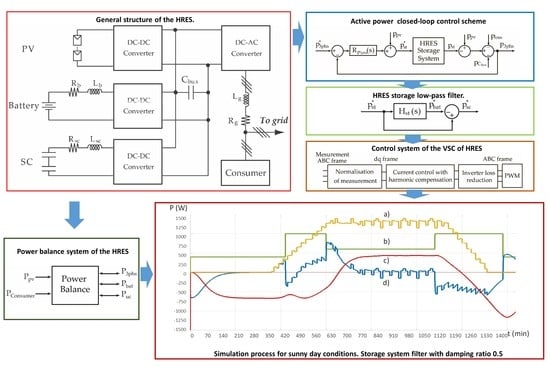
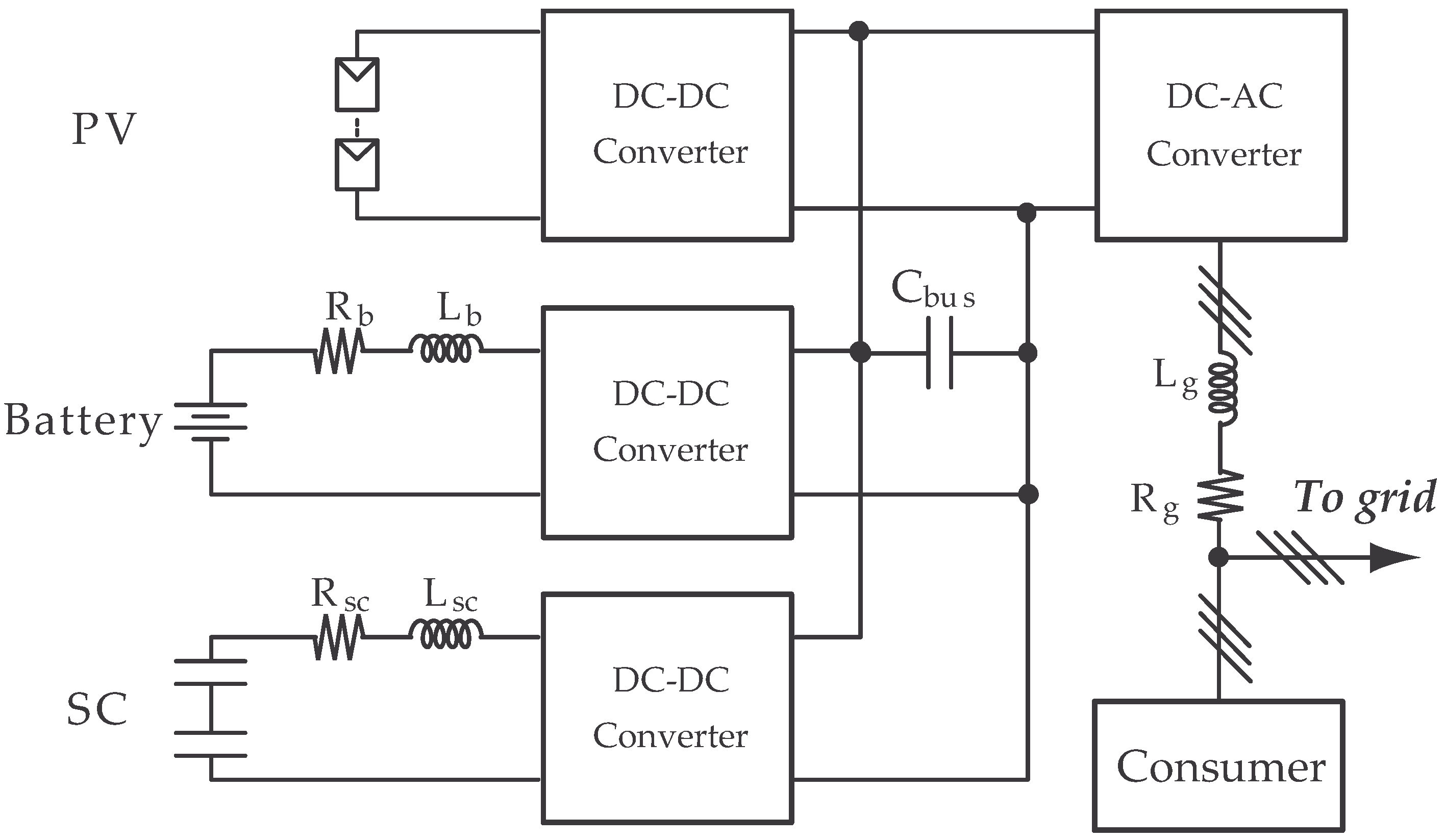
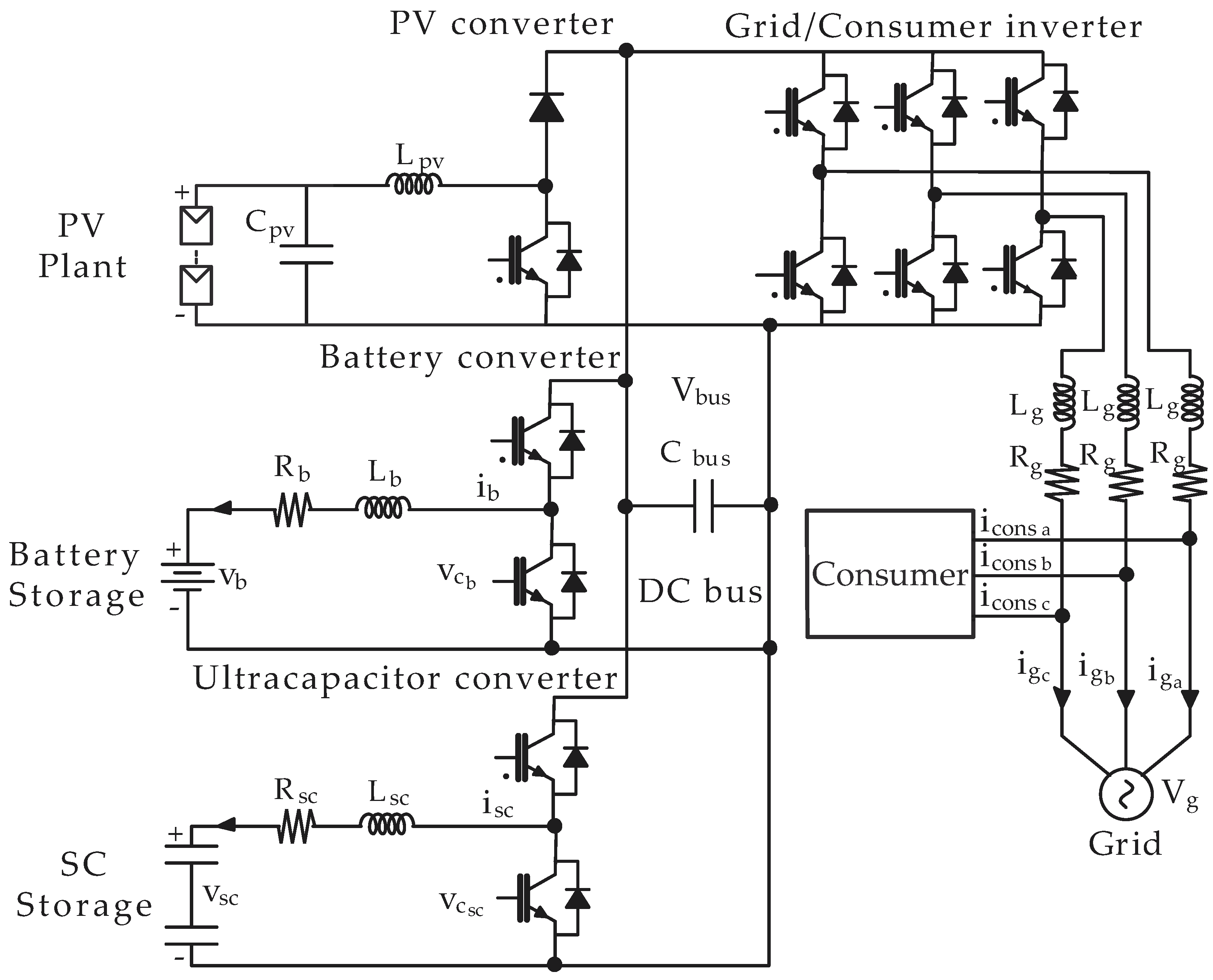
2. Configuration of the HRES

2.1. HRES Model

The HRES considered in this paper contains three parts: a renewable energy generation system, an energy storage system (ESS) and a grid-connection system. The part of renewable production consists of n PV panels connected to a boost DC/DC converter. The output of this DC/DC converter is connected to a common DC bus. Furthermore, this DC/DC converter includes the maximum power point tracking (MPPT) algorithm. The energy storage consists of a bank of batteries and a bank of supercapacitors. Each bank is controlled by a bidirectional DC-DC converter which is connected to the same previously mentioned common DC bus. The HRES is connected to the grid by means of a three-phase inverter plus an inductive filter. The DC side of the three-phase inverter is also connected to the common DC bus. Moreover, three-phase consumers are also connected to the distribution grid, as shown in Figure 1, in which all the HRES elements are depicted.
For the HRES, the simplest way to coordinate all the energy flows is to connect in parallel the DC sides of all the power converters in order to create a main DC bus. This way is known as “Fully Active Topology” [12] of the HRES, which offers better power management than other alternatives. However, in this case, the interaction between different modules of the HRES system may increase the complexity of its parameterization and decrease the stability of the entire system [21].
Figure 2 shows the configuration of the HRES in detail. It comprises the PV plant with the PV converter, the batteries with an associated DC/DC bidirectional converter, the supercapacitors with another DC/DC bidirectional converter, the three-phase bidirectional grid inverter and the capacitor of a DC bus, Cbus. The voltage of the DC bus is maintained at a level necessary for the correct operation of the entire system.
The PV converter, which includes a Maximum Power Point Tracking (MPPT) algorithm, is a unidirectional boost converter. It maximizes the generated power of the PV plant by modifying the operation point.
Two bidirectional half-bridges are used in order to exchange energy from the batteries and the supercapacitors with the DC bus. Consequently, they allow the exchange of energy with the remaining elements of the HRES, i.e., the PV production, the consumer and the grid. The current can flow in both directions, which means that the batteries and the supercapacitors can either store or provide energy.
Moreover, inductive filters are used to connect the batteries and the supercapacitors to their respective converters, being Lb and Rb the inductance and the resistance, respectively, of the connection filter associated to the batteries, and Lsc and Rsc the inductance and the resistance, respectively, of the connection filter of the supercapacitors.
The three-phase section of the HRES consists of the consumer and the grid connection part. A two-level voltage source converter (VSC) is used to connect the DC section of the HRES with the three-phase section. The aim of the VSC is to inject or extract the active power into/from the DC side of the HRES. In addition, it is used to provide the consumer with the necessary power, as well as inject or extract the power into/from the grid connected to the HRES. The VSC is connected to the three-phase section by a first-order inductive filter with inductance Lg and resistance Rg. According to [22], this filter simplifies the process, although there are other alternatives which are more complex and which offer better attenuation of the harmonics associated to the switching frequency of the VSC, such as the use of LCL filters [22]. In this paper, it is considered that the HRES will be connected to a strong grid, and the off-grid operation will happen in an exceptional case. Therefore, the inductive filter can be considered sufficient to filter out the high-frequency harmonics due to the PWM process of the three-phase VSC. According to [23], it was observed that this VSC can be considered as a linear amplifier owing to the high switching frequency employed.

2.2. Model of the DC-bus

The power balance of the HRES indicates an equilibrium between the produced, stored, consumed and exchanged energy, provided that the voltage of the DC bus is constant. As explained in [15], the power generated from the PV plant, ppv, is equal to:
p p v = p C b u s + p 3 p h s + p b a t + p s c p s t + p l o s s
where p 3 p h s is the power injected/extracted into/from the grid and supplied to the consumer, p b a t is the power exchanged with the batteries, p s c is the power exchanged with the supercapacitors, p C b u s is the power exchanged with the capacitor of the DC bus, and p l o s s is the power of the losses due to the filters, the nonideal semiconductors, etc.
The positive sign indicates that the power is injected into the various systems of the HRES, i.e., the storage system, the three-phase section, etc., while a negative sign means that the power is extracted from the system. The instantaneous power of the DC bus capacitor is:
p C b u s = i C b u s v C b u s = C b u s d v C b u s d t v C b u s = C b u s 2 d ( v C b u s ) 2 d t
where i C b u s is the current injected/extracted into/from the capacitor, and v C b u s is the voltage across the capacitor. Equation (2) shows that a constant value of v C b u s indicates that the totality of the power generated by the PV plant is injected into the three-phase section and into the system of the ESS of the HRES.

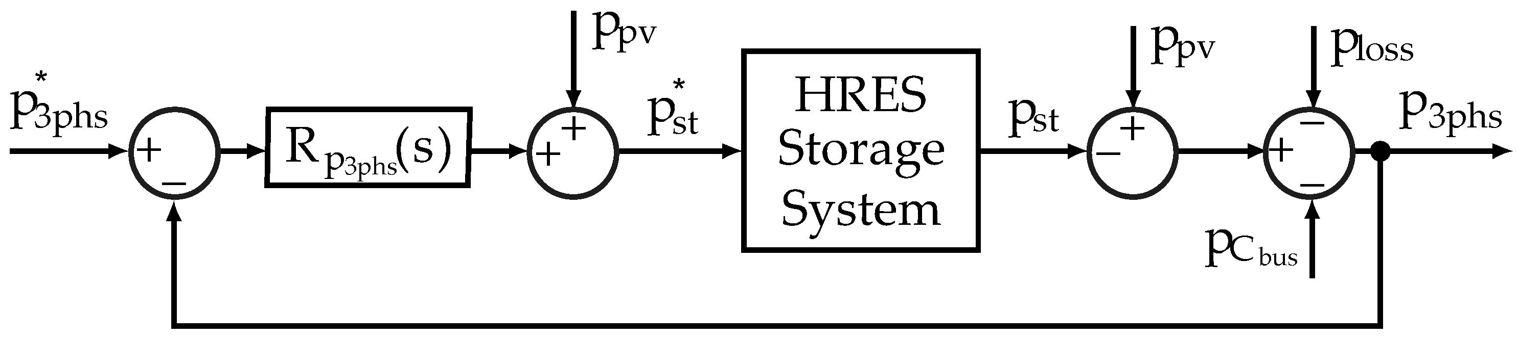
3. Structure of the Control Systems of the HRES

The aim of the HRES’s energy management is to provide the energy demanded by the consumer at any given instant in time. The preferred alternative is that the energy must be provided by the PV plant and the ESS, otherwise by the grid. The energy from the grid can be used in case of insufficiency of the PV plant production and capacity of the storage, in case of accident, or during night time in the absence of renewable production. All depends on the chosen HRES energy management strategies.
There are numerous methods to control the active power injected/extracted into/from the grid or the consumer. One of the simplest solution is to calculate the reference of the storage power p s t * without taking into account the losses due to the connection filters with a structure based on an open-loop scheme [24,25]. Nevertheless, according to [15], a better possible solution is to use a closed loop scheme for controlling the active power, as shown in Figure 3.
This closed-loop system uses an integral regulator R p 3 p h s ( s ) , which allows to remove the steady-state error for step changes in the set point. The transfer function of the integral regulator is:
R p 3 p h s ( s ) = k p 3 p h s s
The calculation of the k p 3 p h s in Equation (3) is carried out assuming that the dynamics of p 3 p h s is much slower than the dynamics of the HRES storage system, which implies that the latter dynamics can be neglected compared with the former. Furthermore, as shown in Figure 3, for compensating the effect of the disturbance in the power production of the PV plant p p v , a feed-forward action of p p v can be added. The power of the three-phase section can therefore be written as:
p 3 p h s = R p 3 p h s ( s ) p 3 p h s * ( s ) 1 p 3 p h s * ( s ) p l o s s ( s ) 1 R p 3 p h s ( s ) p C b u s 1 R p 3 p h s ( s ) = k p 3 p h s s k p 3 p h s p 3 p h s * ( s ) s s k p 3 p h s p l o s s ( s ) s s k p 3 p h s p C b u s
The first-order closed-loop system (4) does not depend on the perturbation p p v and is stable for any negative value of k p 3 p h s . Equation (4) also shows that the output is equal to the reference in steady-state, i.e., s = 0 .

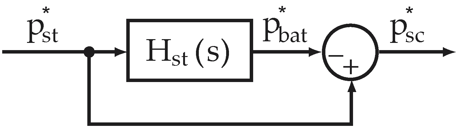
3.1. Control System of the HRES Storage System

The reference of the HRES storage system p s t * is composed of the reference for the battery storage system p * b a t and the reference for the supercapacitor storage system p s t * . According to [24], the profile of the PV plant production can be intermittent and contains high and low frequency oscillations. The aim of the storage system control of the HRES is to use the battery storage only with low-frequency power components, whereas the supercapacitor storage is employed for damping the high-frequency power oscillations and, therefore, smoothing out the power profile [26]. The combination of the battery and the supercapacitor systems in the HRES gives an opportunity to improve the stability and flexibility of the complete system, and significantly extend the lifetime of the battery storage system [27]. This objective is very important, since nowadays a batteries storage system is rather expensive, and its lifetime can be less than five years. It should also be considered that its lifetime can decrease with poor operating conditions.
This problem can be reduced by including a low-pass filter in the control loop of the ESS as that proposed in [15], which splits the high-frequency part of the reference for the supercapacitor and the low-frequency part for the battery storage system, as shown in Figure 4.
As a filter, a low-pass second-order filter Hst was chosen. As indicated in reference [24], a first-order filter might not be sufficient for limiting the value of the battery reference when the value of the power of the storage system is very high. As a proposed solution, the second-order filter allows a longer delay in the response of the battery power, if compared with the response obtained with a first-order filter, and, therefore, the supercapacitors provide a higher peak of power. The filter is defined by Equation (5):
H s t ( s ) = ω n 2 s 2 + 2 ζ ω n s + ω n 2
where ω n is the natural frequency, ζ is the damping ratio and s is the Laplace operator.
As shown in [15], the control schemes of the batteries and the supercapacitors converters employ a current-control loop with PI regulators to guarantee zero-tracking error in steady-state for constant references [28]. The measured current from the battery or the supercapacitor is compared with the reference from the ESS, and the difference goes to the closed loop of the PI regulation.

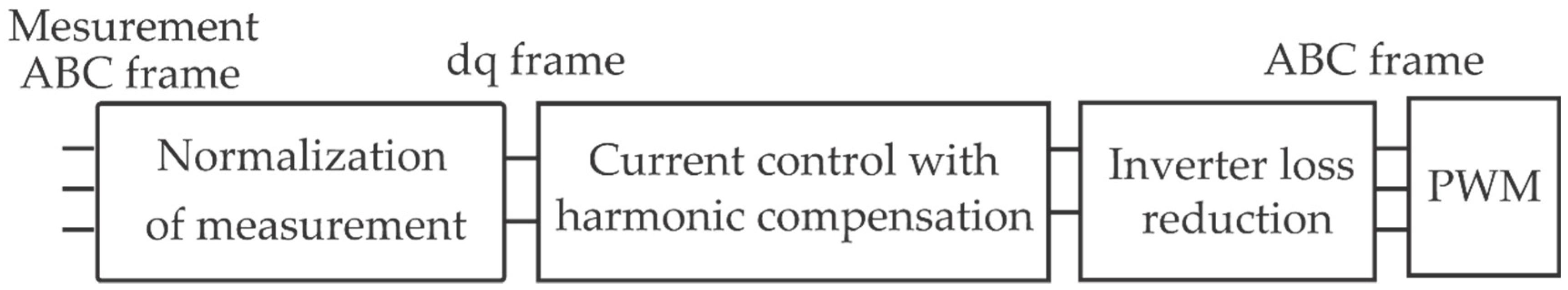
3.2. Control System of the DC bus and the VSC of the HRES

The control objective of the DC bus system of the HRES is to maintain the required DC voltage level for the correct HRES operation. Due to the irregular PV plant production, the storage system power interactions, etc., the constant DC level target becomes quite important. Moreover, the three-phase voltage source converter (VSC) needs to allow the bidirectional interchange between the internal DC part and the external three-phase part of the HRES. In the three-phase section of the HRES the consumer can only absorb the power from the HRES and the grid. As shown in Figure 1, the grid is used for the absorption of the extra power produced by the PV plant or delivered by the HRES and not consumed by the consumer. Alternatively, the grid provides energy to the consumer and the systems of the HRES in case of insufficient production of the PV plant and the storage capacity, or absence thereof. In case of the grid connection, the grid keeps the voltage level in the three-phase section, and the HRES injects the required current for the consumer. In case of remaining extra PV production, the HRES injects the extra power into the grid (grid injection case).
Furthermore, the VSC needs to comply with the grid codes and the consumer restrictions about quality of the power. It must comply with the harmonic limits established by several standards, e.g., IEEE 929, IEEE 1547 and IEC 61727, which suggest limits for the current total harmonic distortion (THDi) and the magnitude of each harmonic. In order to fulfill these restrictions and minimize the harmonic content, multiple control subsystems for the VSC control are required [29]. For this goal, three subsystems are developed in this paper, namely, a normalization scheme, a control subsystem and an inverter loss reduction. Figure 5 shows the detailed schema of the VSC control subsystems with indication of the signal reference frames.
The first subsystem is “Normalization of measurement”. It is used to normalize the current signal measurements from the three-phase section of the HRES in order to eliminate the measurement noise, common harmonic perturbations, unbalances between phases and other disturbances. In addition, it synchronizes the current measurement reference with the frequency of the grid voltage. It is implemented by applying the rotated reference frame (RRF) ( d q frame). The output of this subsystem also represents the measurement signals in the RRF.
The second subsystem is the “Current control with harmonic compensation”, which is used to control the active and reactive powers exchanged with the grid. This subsystem uses PI controllers for the current flow control in the d q frame. According to [30], the 6th and 12th harmonics are present and have a big impact in the RRF for balanced three phase systems. For this purpose, the active proportional resonant (PR) controller compensation of the 6th and 12th harmonics was used.
In three-phase inverters, the "voltage loss" can be reduced without decreasing the quality of the output voltage and the input currents. Therefore, the subsystem “Inverter loss reduction” uses the method of the third-harmonic injection to improve the efficiency of the three-phase inverter. Firstly, it changes the rotated reference frame to the stationary reference frame to generate the voltage reference. Before entering in the pulse-width modulation (PWM) algorithm, the voltage reference is modified by the addition of a third harmonic component. Finally, the PWM generates the firing signal for the switches of the VSC. Each subsystem is explained in the subsections below.

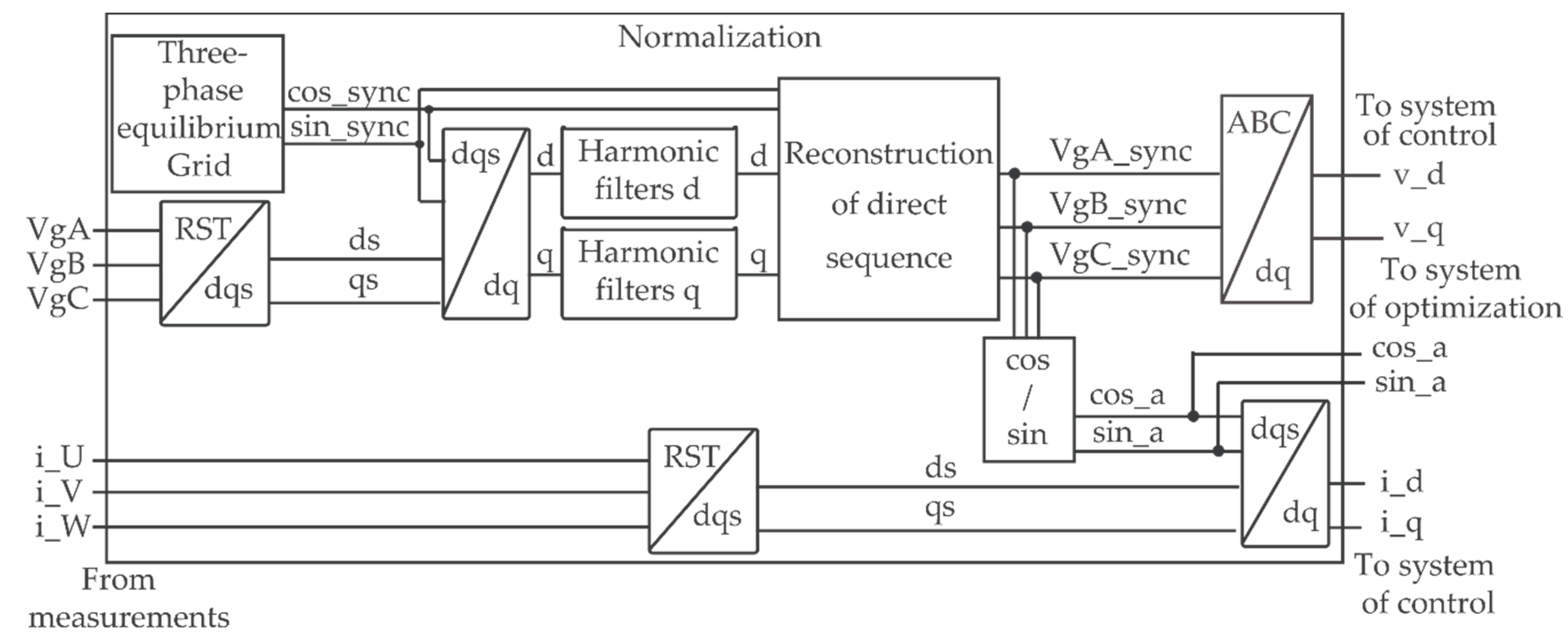
3.2.1. The Subsystem “Normalization of the Measurement”

The three-phase section of the HRES is connected to the consumer and the grid. This implies that the frequency, amplitude and phase of the fundamental sequence components of the grid voltage must be estimated [31], since an estimate is necessary to fulfil the grid codes and achieve a high-performance response from the control system in the case of the grid connection.
Many solutions have been proposed over the past few years for the synchronization with the grid. These solutions can be classified into two main groups. The first group methods use the RRF to implement a phase-locked loop (PLL) and a disturbance filtering. The alternatives of the second group are based on the fixed reference frame (FRF) and employ frequency-locked loops with frequency-adaptive filters. Furthermore, reference [32] implements an alternative method based on an open-loop scheme with predictive filters, which is able to estimate the fundamental sequence of the grid voltage within a ±2 Hz deviation interval with regard to the rated frequency.
As the synchronization method must be fast and robust, one of the best solution is the alternative proposed in [31]. This method uses a filtering stage implemented in a rotating reference frame (RRF). The filters chosen are notch filters [33] because of their simplicity, computation burden and the possibility to reject possible harmonic components in a wide range of frequency.
The “Normalization” subsystem of measurements is depicted in Figure 6.
The first step of the “Normalization” process is to transform the measurements of the grid voltage into two orthogonal components, i.e., d q components, using an RRF. The rotated reference frame with a virtual balanced grid with nominal frequency of 50 Hz is applied in order to reject the most common disturbances due to the imbalances of the grid voltage.
The next step is to use the filters in the RRF to eliminate possible harmonics from d and q components. In balanced three-phase systems the most important harmonics are the 1st, 5th, 7th, 11th, 13th, 17th, 19th, etc. [34]. The 5th and 7th harmonics are transformed into a 6th harmonic into the RRF, the 11th and 13th harmonics are transformed into a 12th harmonic, and the 17th and 19th harmonics are transformed into a 18th harmonic etc. [35]. Nevertheless, in the case of an unbalanced three-phase system, these harmonics will be transformed into the 4th, 6th, 8th, 10th, 12th, 14th, 16th, 18th, 20th, etc. According to [31] and [36], in order to reject a harmonic component in a wider frequency interval, the second-order notch filters will be used. The filter transfer function is defined by Equation (6):
H h ( z ) = k h ( 1 2 cos ( ω h T s ) z 1 + z 2 ) , k h > 0
where T s is the sampling period, ω h is the frequency to remove the harmonic of order h , and the parameter k h is adjusted to obtain a certain gain at a particular frequency (e.g., unity static gain).
The frequency response of H h ( z ) is equal to zero at frequency ω h . These harmonic filters will be connected in series and will be tuned at even components of frequencies ω h = h ω 1 , with h=0, 2, 4, 6, …, 26.
As shown in Figure 6, after the filtering step the signal goes through the RRF to FRF transformation. After that, the measured voltage signal was used in the current normalization process and current control subsystem.
The measured current signal goes through the direct-quadrature-zero transformation (DQZ). The obtained d s and q s components are used in the inverse D Q Z d q transformation with sin _ a and cos _ a from the voltage normalization process as the reference of the RRF. Further, the obtained d q components of current measurement signals goes as the input to the current control subsystem.

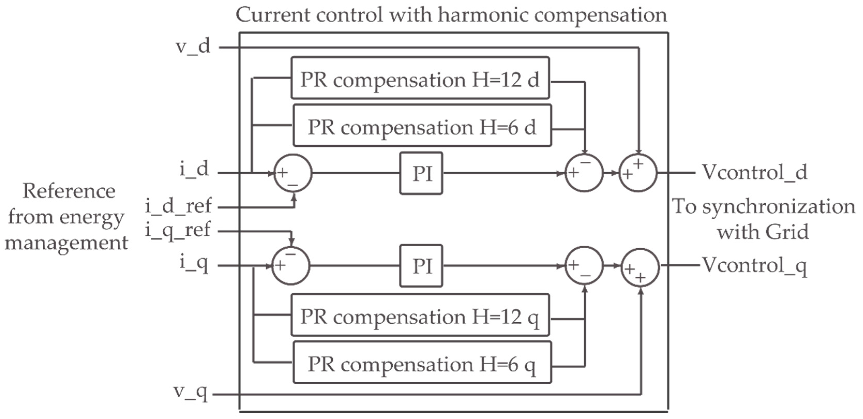
3.2.2. The Subsystem “Current Control and Harmonic Compensation”

From combination of Equations (1) and (2) we obtain another equation of the voltage in the DC bus as:
d ( v C b u s ) 2 d t = 2 C b u s ( p p v p 3 p h s p s t p l o s s ) = 2 C b u s ( p p v v 3 p h s i 3 p h s p s t p l o s s )
It follows from (7) that the voltage of the DC bus of the HRES v C b u s depends on the voltage v 3 p h s and current i 3 p h s that comes from/to the three-phase section of the HRES or by the power of the HRES storage system p s t . As discussed in this paper, when the HRES is constantly connected to the grid, the v 3 p h s is constant. Only the current i 3 p h s of the three- phase section remains, whose d and q components represent the active i 3 p h s d and reactive current i 3 p h s q components respectively [37]. The control of the DC bus voltage needs an implementation of a closed control loop system of these components. One of the most common method of current control in the RRF is the use of PI regulators [38].
According to [15], the PI controllers transfer function for the d and q current component control are represented in Equation (8) and Equation (9) respectively:
W d ( s ) = K i 3 p h s I 3 p h s d * ( s ) I 3 p h s d ( s ) s K p 3 p h s I 3 p h s d ( s )
W q ( s ) = K i 3 p h s I 3 p h s q * ( s ) I 3 p h s q ( s ) s K p 3 p h s I 3 p h s q ( s )
The terms I 3 p h s * and I 3 p h s are the reference and the actual value of current for d and q current component, whereas the K p 3 p h s and K i 3 p h s are the proportional and the integral gains of PI controllers, respectively. PI controllers will provide zero static regulation error for the d and q current component control.
Figure 7 shows the scheme of the current control system and can be applied to the system of active harmonic compensation, which will be described below.
The difference between the reference of the current from the energy management system of the HRES and the measured current from “Normalization” subsystem is driven to the PI controller, as described above. Although the use of PI controllers is a very easy and robust solution for the current control, a PI is not able to follow a sinusoidal reference with zero steady-state error due to the dynamics of the integral term [39]. In the case of a balanced grid, the d and q components are constant in the RRF. However, in the case of an unbalanced grid, harmonics in the d and q components of the grid voltage will be present. Consequently, these harmonics will induce harmonic components into the grid current. These current harmonics cannot be removed by the PI controller and, for that reason, a system of active compensation of harmonics will be used.
This system employs Proportional Resonant controllers (PR) [40], which introduce an infinite gain at a selected resonant frequency for eliminating the steady-state error at that frequency. According to [41], the flexibility of tuning the resonant frequency of PR controllers allows to use them for a selective compensation of low-order harmonic frequencies without requiring excessive computational resources [42].
One of the general equations of an ideal PR controller is the following:
G p r ( s ) = K p + K r ( s ) s s 2 + ω 0 2
In Equation (10) K p and K r are the proportional and resonant gain terms, respectively, and ω 0 is the resonant frequency. The ideal PR controller provides an infinite gain at the frequency ω 0 , and no phase shift at the other frequencies [39]. To avoid the instability due to the infinity gain in case of frequency deviations, the PR controller can be enhanced by the insertion of damping in an ideal PR controller. This allows to obtain a non-infinity gain at the frequency ω 0 , as shown in Equation (11):
G p r ( s ) = K p + K r ( s ) 2 ω c s s 2 + 2 ω c s + ω 0 2
where ω c is the bandwidth around the frequency ω 0 .
According to [43], all the harmonics that are multiples of three can be assumed to be blocked by Park’s transformation. As stated in Section 3.2.1, the most important harmonics in the RRF are the 6th and the 12th components. As Figure 7 shows, the d and q components of the current go to the two PR controllers placed in parallel. These controllers are non-ideal PR controllers tuned to h = 6 and h = 12 harmonics with the bandwidth around the resonant frequency of 2 Hz. Regulated impacts of PR controllers are deducted from the PI regulation impact. This allows to remove the 6th and the 12th harmonics from the d and q current components. The PWM algorithm uses the voltage signal as its reference. Thereafter, obtained regulatory impacts for current measurements is summed up with the d and q voltage components from the subsystem of normalization. This is done in order to control the current by the use of the voltage reference for PWM [44].

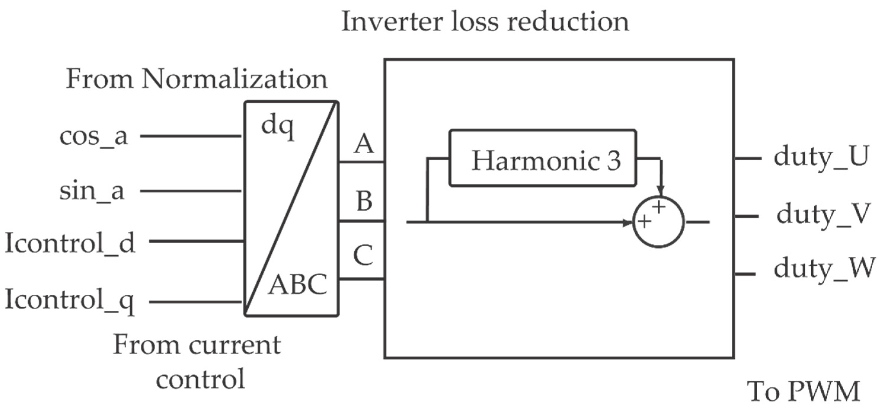
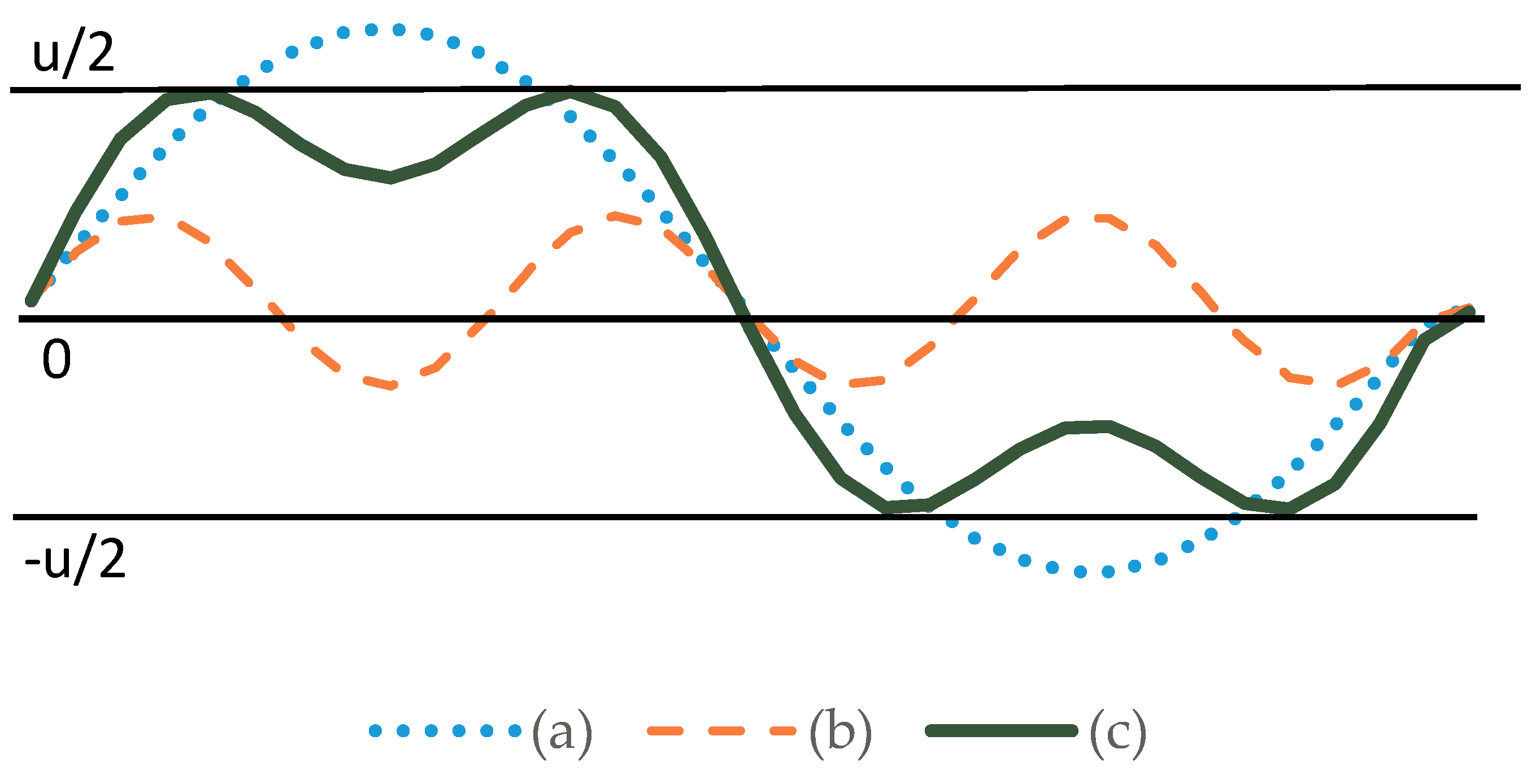
3.2.3. The Subsystem “Inverter Loss Reduction”

There are two main types of losses in three-phase inverters: the voltage and the switching losses. There are different methods to reduce them, e.g. reducing the switching losses by modification of the PWM algorithm [45]. Nevertheless, the easiest and most efficient method is the reduction of the voltage loss by injection of the third harmonic. This method works without decreasing the quality of the output voltage and input currents. Since the harmonics of rank 3 or multiple of 3 are eliminated from the output voltages, in order to optimize the reference wave, the third harmonic can be subtracted from the reference sinusoidal signal followed by PWM [46], as shown in Figure 8. This optimization is named suboptimal control.
Figure 9 shows the third-harmonic injection process. The optimized sinusoid (c) is the sum of a fundamental component (a) and a harmonic of order 3 (b). The theoretical maximum of the phase-to-neutral fundamental voltage changes from U / 2 , with sinusoidal control, to 1.155 U / 2 [46] with “Inverter loss reduction” subsystem, and is depicted in plot (a). As can be seen from Figure 9c, the optimized sinusoid does not exceed the U / 2 level. This helps to reduce the voltage loss by a factor larger than two.
Thereafter, the generated signals are driven to the PWM process in order to generate the firing signals for the switches of the VSC.

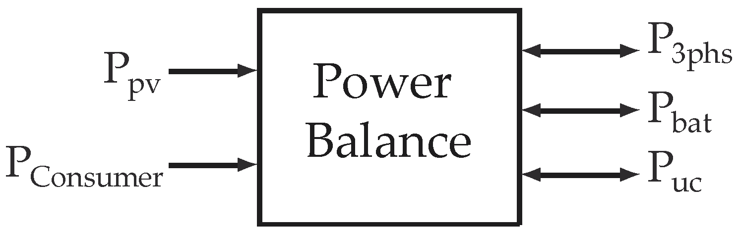
4. Power Balance and Energy Management Strategies

The power balance system of the HRES is one of the most important elements of the energy management. The aim of this system is to coordinate the energy flows generated by all the subsystems of the HRES. The power balance system controls the charge and discharge of the batteries and the supercapacitors, the energy injected/extracted into/from the three-phase system of the HRES and also the voltage of the DC-bus. Figure 10 shows this system with the variables involved in the process.
As it is shown in Equation (1), the power generated by the PV plant is equal to the power exchanged in the storage system, plus the power exchanged with the three-phase section and the power losses.
The energy management strategies of the power balance system of the HRES operate all flows of the energy of the HRES at every instant. The algorithms of the energy strategies branch into a number of options, containing dozens of work states depending on input and output parameters. There are, therefore, many strategies for the HRES operation. They depend on the place of use and the HRES functionality. Some common strategies for the majority of the HRES systems will be explained below:
1)
The priority is to provide the consumer with the energy generated by the PV plant.
2)
If the energy generated by the PV plant exceeds the energy requirements of the consumer, this excess of energy will be stored in the storage system of the HRES. If the energy storage system is fully charged, the energy will be injected into the grid.
3)
If the PV plant production is not sufficient to fulfill the energy requirements of the consumer, the energy storage system will compensate the deficit of energy between the energy generated by the PV plant and the energy demanded by the consumer. In the case that the energy demanded by the consumer is larger than the sum of the energies generated by the PV plant and provided by the storage system, the necessary energy will be provided by the grid (according to the Kirchhoff’s circuit laws [47]).
4)
In case of absence of the grid, and if the energy requirements of the consumer exceed the energy generated by the PV plant plus the energy provided by the storage system, the consumer must be disconnected because of the impossibility to fulfill the energy consumption requirements by the HRES.
The energy management strategies can take into account many aspects. One of them can be the prediction of the energy generation of the PV plant according to the weather forecast and the price of the electricity established by the energy market. Another factor is the hourly cost of the electricity provided by the grid. These factors can generate different possibilities, such as:
The injection of the power of the HRES into the grid when the price of the energy implies an economical benefit. The rest of the time, the extra renewable energy generated is stored in the storage system of the HRES.
To store the energy provided by the grid in the storage system of the HRES when the price is low, and then use it to provide the consumer with the energy stored when the electricity price is more expensive.
To store the energy provided by the grid in the ESS when the price of the electricity is low, and reinject this stored energy into the grid when the price is higher (network strengthening [48]), and many other options.

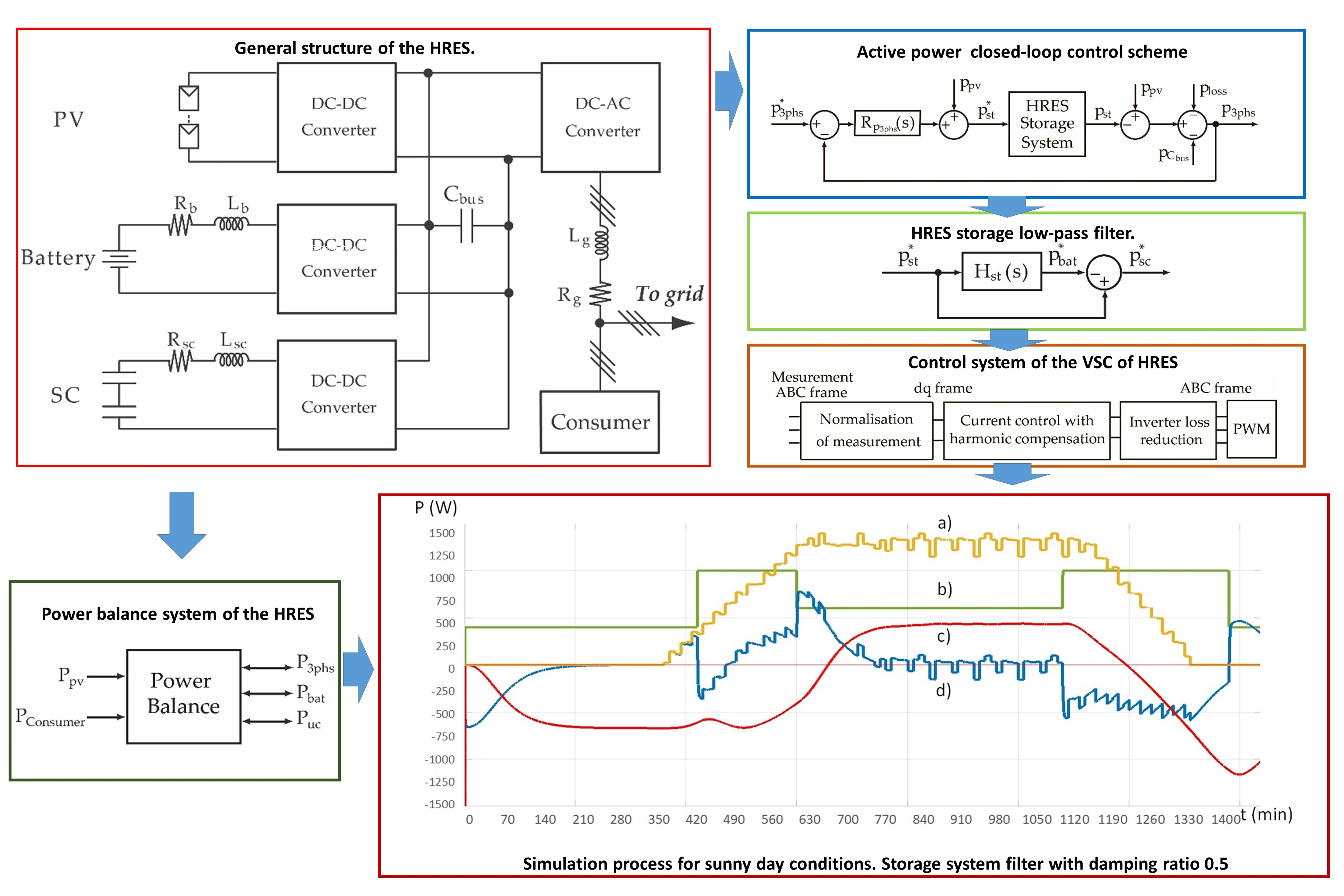
5. Simulation Results

5.1. Simulation Model

At first, the HRES previously studied will be simulated by using Matlab/SIMULINK (R2018a, Mathworks, Natick, MA, USA) software. The HRES depicted in Figure 1 was implemented by using an average model as it provides good results for large simulation time periods. The general scheme used for simulation is represented in Figure 2.
Table 1 lists the parameters for the battery storage system of the HRES.
Table 2 summarizes the parameters for the SC storage system of the HRES.
Table 3 shows the parameters for the DC and the three-phase part of the HRES. Mathematical models and transfer functions of the control system of the HRES and the HRES storage system were represented in [15] for Table 1 and Table 2, in Section 3, and in Section 3.1 for Table 3.
The values of the resistances, inductances and capacitances specified in Table 1, Table 2 and Table 3 are the same as those used in the experimental prototype (see Section 6.1 for more details). These parameters have been designed according to several design specifications that are not unique and depend largely on several technical and /or economic factors.
The experimental prototype was designed for a 3 kW HESS, and the worst possible operating conditions are assumed in order to calculate the parameters of the system, i.e. establishing that all the demanded energy is delivered by the HESS. Moreover, in order to completely define the parameters of the experimental prototype, the following variables were taken into account: (a) the maximum voltage of the DC link, (b) the switching frequency of the converters, (c) the operation voltages of the batteries and supercapacitors, and (d) the maximum ripple in the current of the output converters.
The proportional and integral gains of the various controllers have been obtained using the root-locus technique and the following design specifications:
  • The poles of the closed-loop transfer functions are real and located on the left-hand side of the complex plane in order to avoid the overshoot in the time responses. Nevertheless, other criteria can be used for placing the poles.
  • The pole of the control scheme used to control the active power exchanged with the three-phase section of the HRES is placed at s = −2.5 rad/s.
  • In accordance with [6], the current controllers of the DC–DC converters associated with the batteries and the ultracapacitors are tailored to locate the two poles of both closed-loop systems at s1 = s2 = −1000 rad/s. Furthermore, the PI controllers for the d and q components of the current injected into the grid are also designed to obtain closed-loop poles placed at s1 = s2 = −1000 rad/s.

5.2. Simulation Process
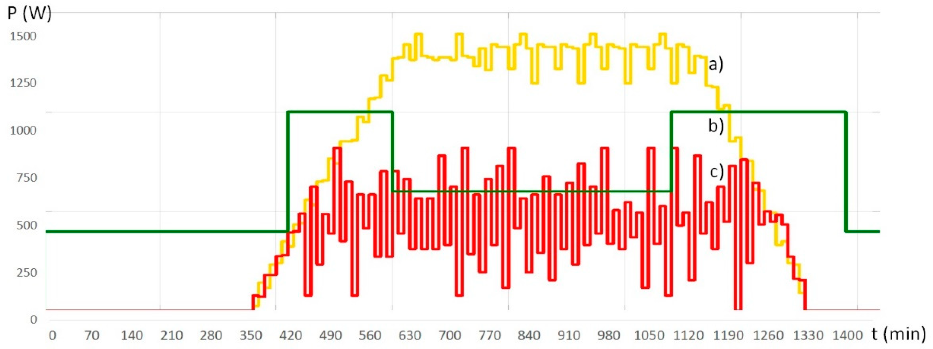
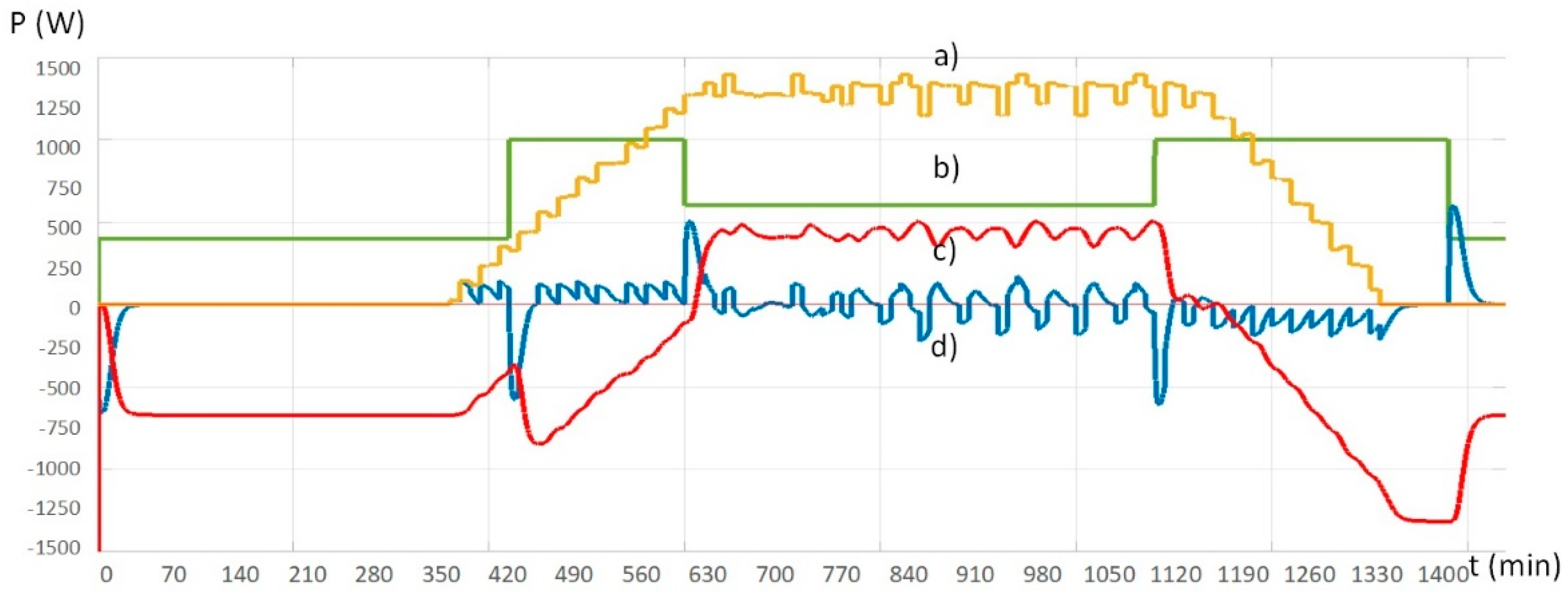
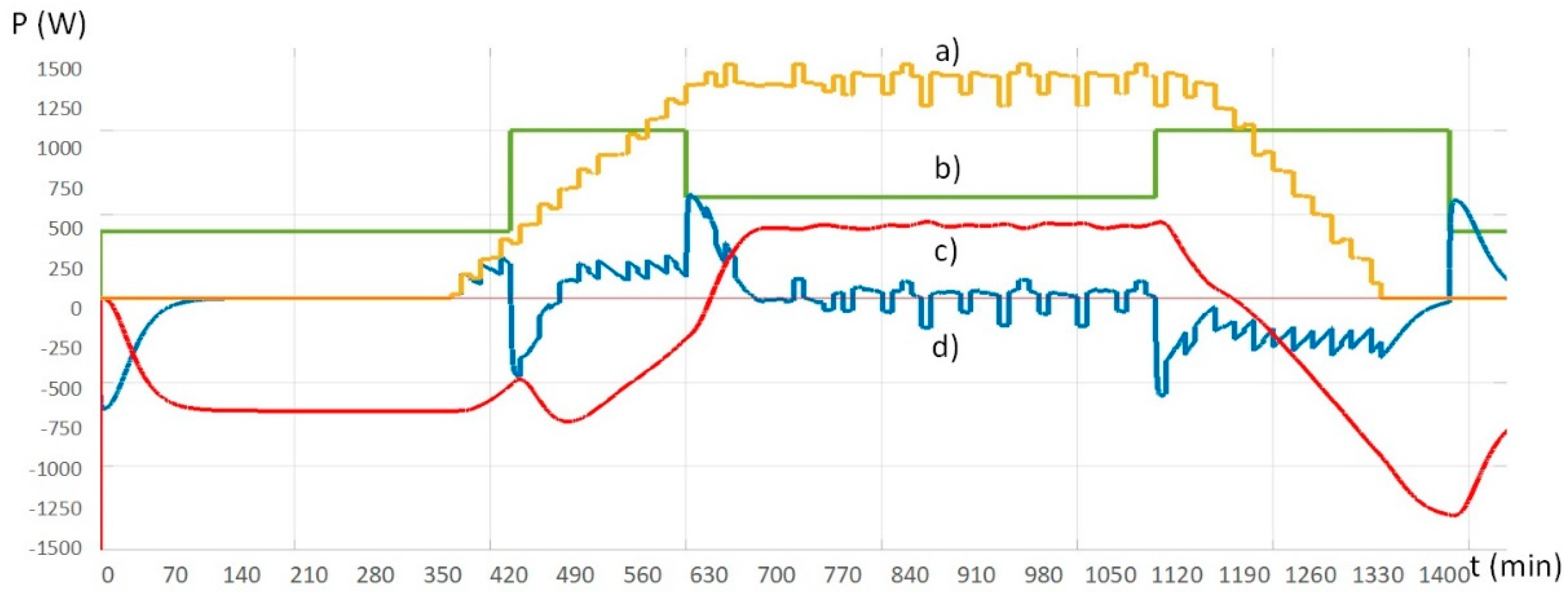
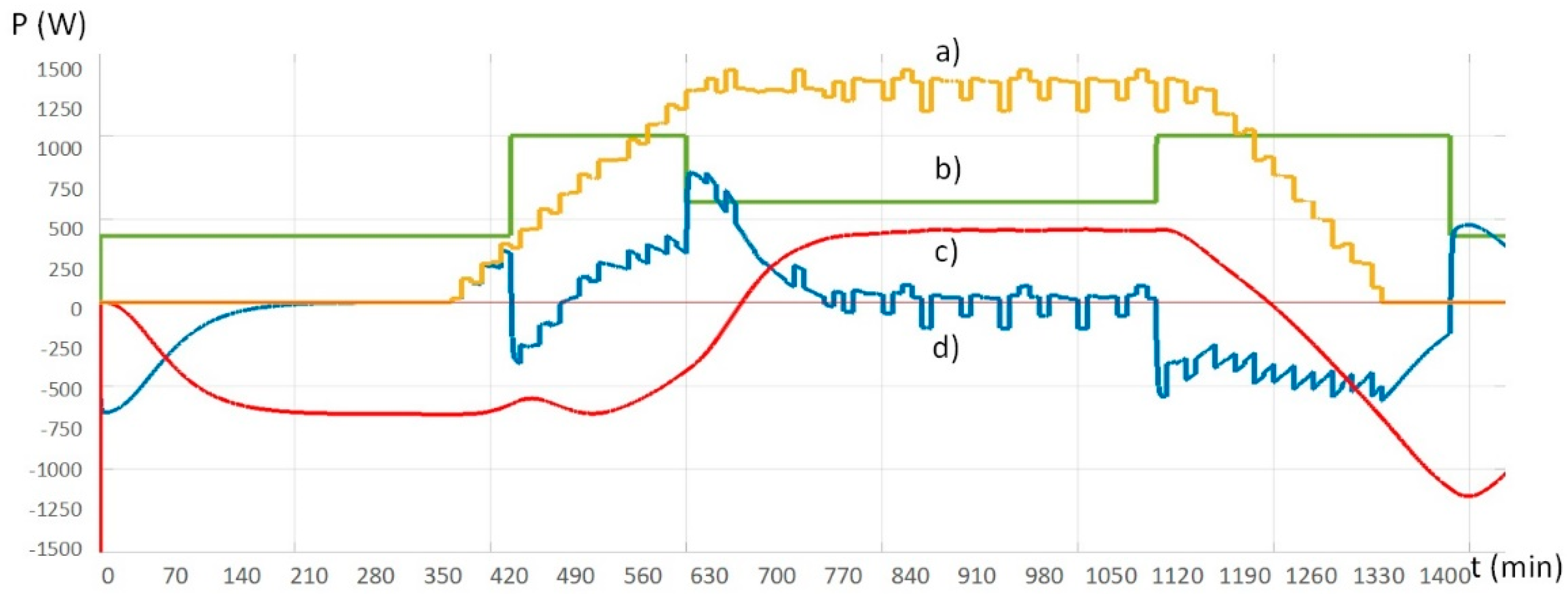
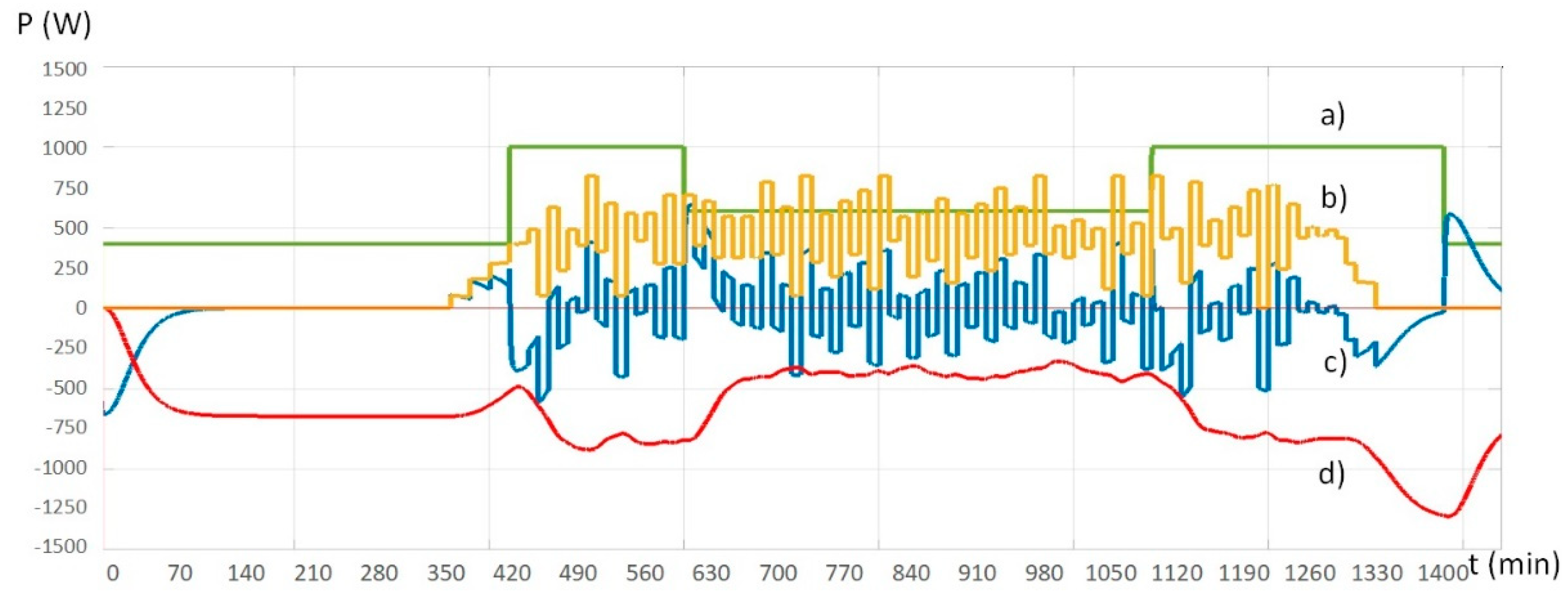
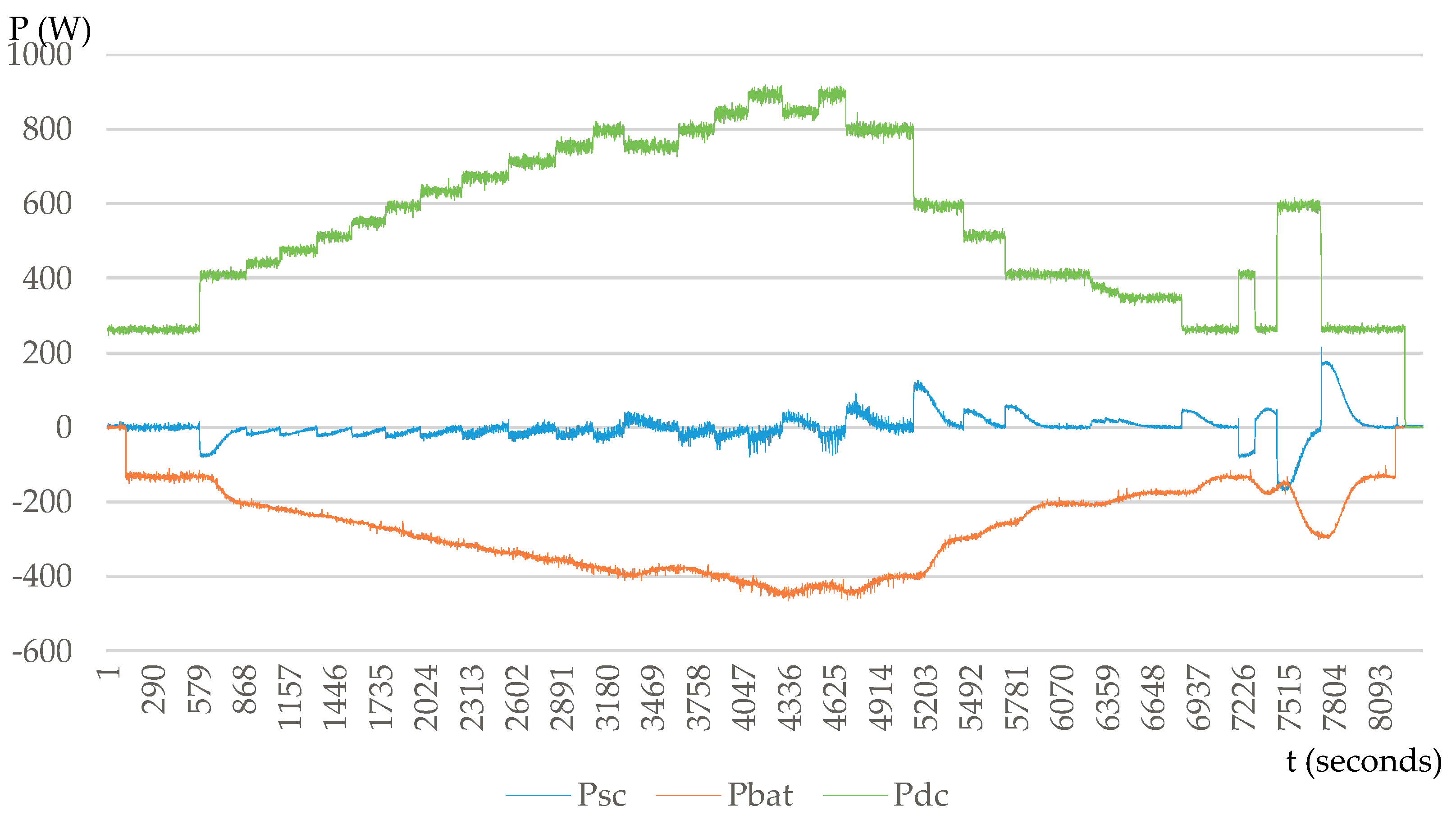
For the simulation scenario the 24 hours simulation of HRES system was chosen. According to [49,50] two of the most significant probability amplitude profiles (PAP) for the PV production were chosen. They represent a sunny and a cloudy day for the high and low daily solar insolation conditions respectively [51]. This will allow to observe the behavior of the simulated HRES system under different operation conditions. The input parameters for the HRES system simulation are the profiles of the PV production for a sunny and a cloudy day, and the required power by the consumer, as shown in Figure 11.
The PV plant production profile includes high and low frequency oscillations, as well as the increase and decrease in the generation in the morning and evening hours, respectively. The general requested power profile of the consumer includes the low energy demand during the night hours and afternoon, as well as the morning and evening pick demand hours [52].
The main aim of the energy management system in the simulated case is to provide all the consumer required energy by the HRES. The HRES will supply the consumer and store the excess in the storage system. In absence of the PV energy generation (night time), the energy storage system will supply the consumer by itself.
The main goal of the supercapacitors is to absorb the high frequency oscillations in the storage reference in order to increase the lifetime of the batteries, and to enhance the stability and quality of power in the HRES.
The objective of this simulation is to analyze the behavior of the HRES system, and particularly the ESS: the interaction of supercapacitor and battery storage system considers the influence of the damping ratio ζ on the implemented low-pass HRES storage system filter in the HRES operation and durability.

5.3. Results

Three cases of low-pass filters of the storage system of the HRES for two different weather conditions have been simulated. These are the second order filters described in the Section 3.1, with coefficients of the damping ratio ζ equal to 0.1, 0.25 and 0.5. For a sunny day the results are shown in Figure 12, Figure 13 and Figure 14, respectively.
The second weather scenario is a cloudy day. The results for the damping ratio ζ equal to 0.1, 0.25 and 0.5 are shown in Figure 15, Figure 16 and Figure 17, respectively.
Initially the supercapacitor absorbs the high frequency oscillations of the power in the HRES. In case of low frequency components, the battery storage reference also starts to absorb/inject energy, but more slowly due to the filter.
A higher value of the linear coefficient H 1 increases the time response of the second order low pass filter and, as a consequence, smooths the battery storage power profile. The higher value of the damping ratio ζ of the storage system filter allows to reduce the battery charge/discharge operation during high frequency oscillations due to intermittent PV plant production. This avoids the situation when the power required by the consumer and the PV plant production have comparable dimensions in some periods of time. Figure 12 and Figure 15 show how the low value of the damping ratio ζ of the storage system filter in some cases leads to a “microcycle“ operation [53] of the storage system, i.e., a frequent change of direction of the current of the storage system, particularly in the battery bank. The PV production has high and low frequency oscillations and the storage system absorbs them. Due to the insufficient damping ratio value, the storage system filter will pass some high frequency oscillations to the battery storage control system, and the battery will react. When the PV plant production has similar power level as the power required by the consumer, the battery storage power will oscillate around zero, which will be equal to the numerous charge/discharge storage system cycles, i.e. the “microcycle“ operation. When the supercapacitor storage system is created for this type of operation, this leads to rapid irreversible degradation of the batteries lifetime and performance [54].
It can be noted from Figure 13, Figure 14, Figure 16 and Figure 17 that the higher value of the damping ratio ζ of the storage system filter allows the storage profile to be smoother and avoid the appearance of the “microcycle“ operation. On the other hand, a very high ratio of the damping ratio ζ of the storage system filter increases the time response, which in turn in certain cases can lead to the depletion of supercapacitor storage system before the battery storage system starts to respond. This will lead to an imbalance in the power offer and demand and failure of the HRES.

6. Experimental Results

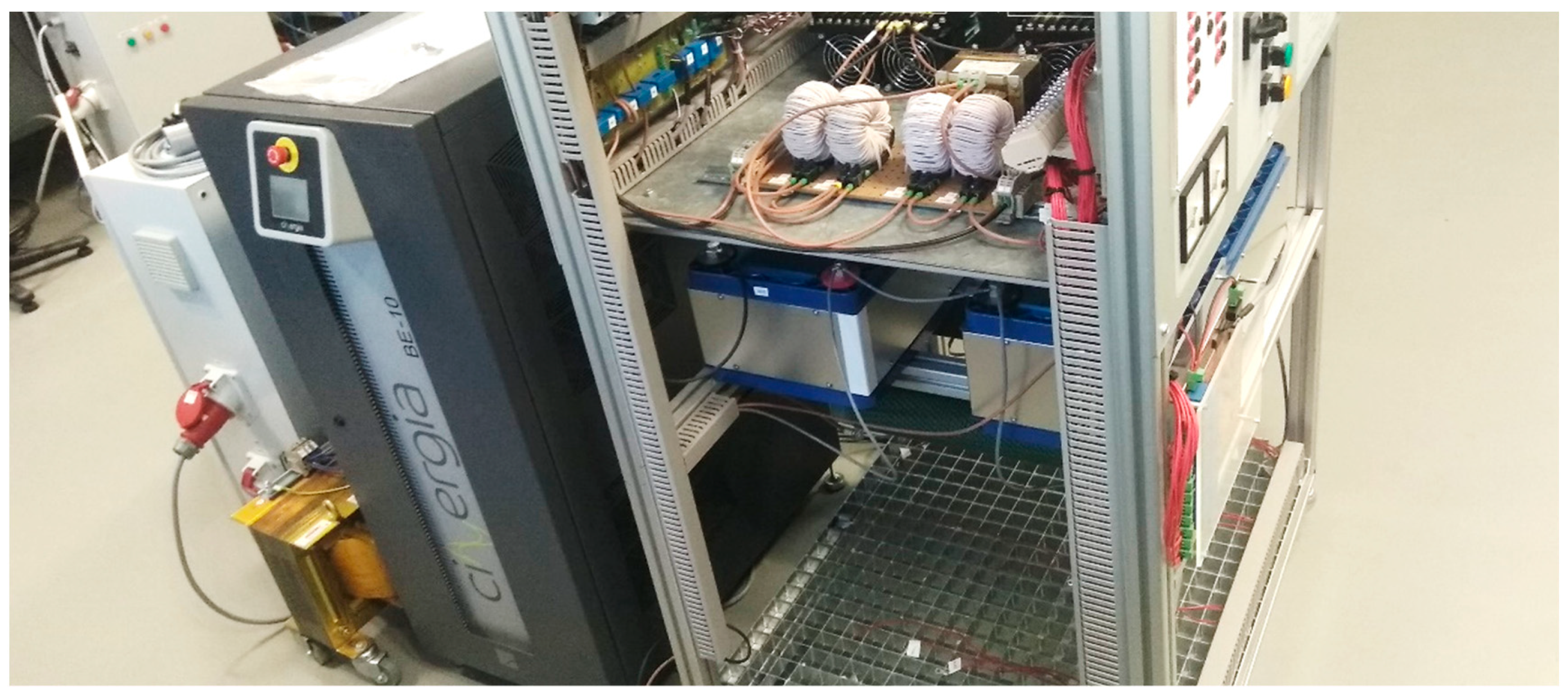
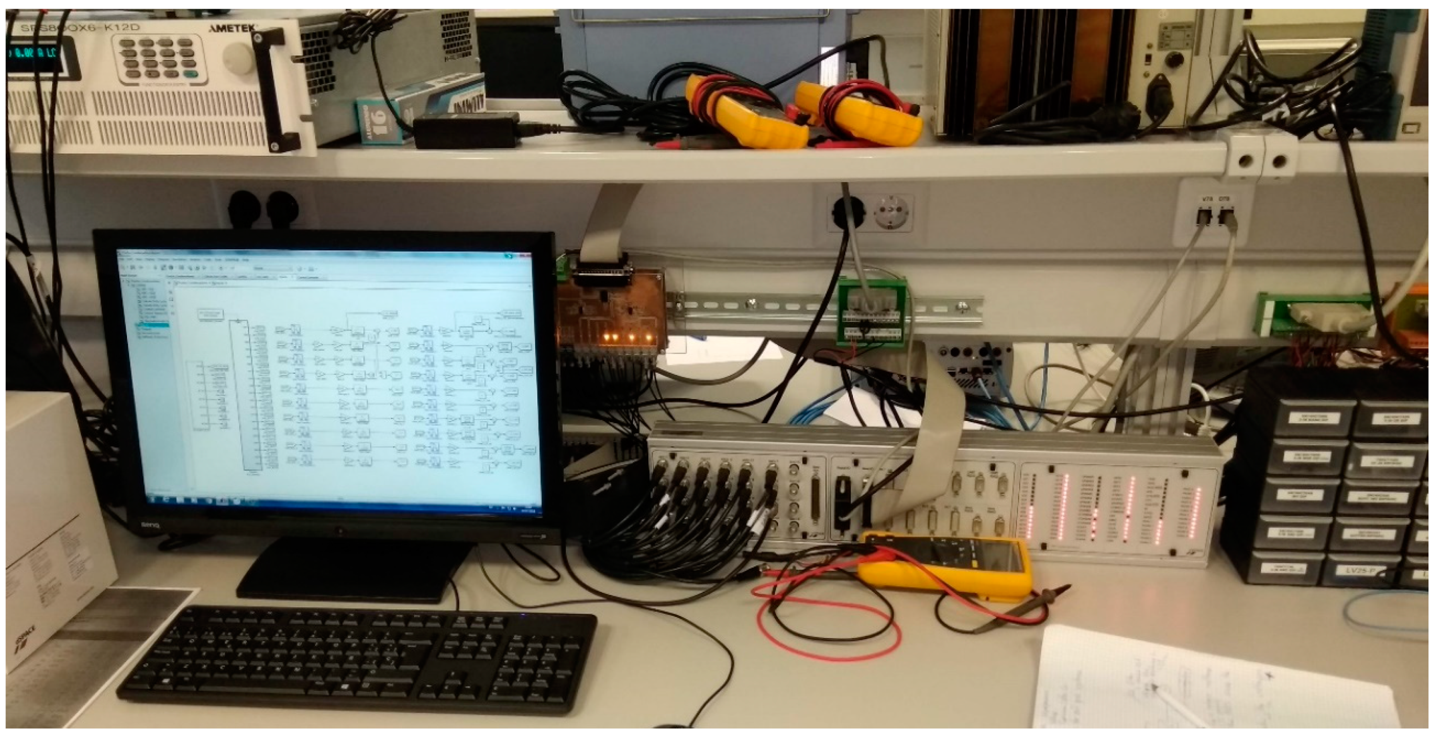
6.1. Experimental Model

The purpose of the practical test is to validate the damping ratio ζ influence on the storage system of the HRES. This paper puts an emphasis on the storage system filter, and as a consequence, the storage-system interaction with the DC bus will be studied. The experiment prototype consisted of the battery and supercapacitor storage systems, the consumer simulated by a passive load and the DC bus with PV plant production emulated by a DC power supply.
The DC/DC bidirectional converters of the batteries and supercapacitors are implemented using two commercial three-phase IGBT inverters SEMIKRON SKS 22F B6U + E1CIF + B6CI 13 V12 (Semikron Electronics S.L.U., Barcelona, Spain) (the rated current is 22 A, while the maximum voltage is 1200 V and the recommended maximum switching frequency is 6 kHz), which are represented in Figure 18.
In order to use the inverters as DC/DC bidirectional converters, only one leg per inverter is employed. The supercapacitors are two Maxwell BMOD0094 P075 B02 (Maxwell Technologies, Inc., San Diego, CA, USA) (the rated voltage is 75 V, the rated current is 100 A, the absolute maximum current is 1,900 A) connected in series, with common capacity of 47 F, which are shown in Figure 19.
The battery storage was emulated by a Battery Emulator from CINERGIA with the voltage of the simulated batteries equal to 50 V. This is a regenerative AC/DC converter designed to emulate a battery behavior (from 20 to 750 V). The passive load is represented by three resistances of 470 Ω connected in parallel with a common DC bus. The programmable DC power supply AMREL SPS800X6-K12D (AMETEK Programmable Power, San Diego, CA, USA) (maximum voltage rating is 800 V, maximum current rating is 6 A, maximum output power is 1200 W) is used to simulate the PV plant generation. All the systems are connected to the DC bus. The control scheme was created by using Matlab/SIMULINK software with the dSPACE1103 platform, as shown in Figure 20.

6.2. Experimental Process
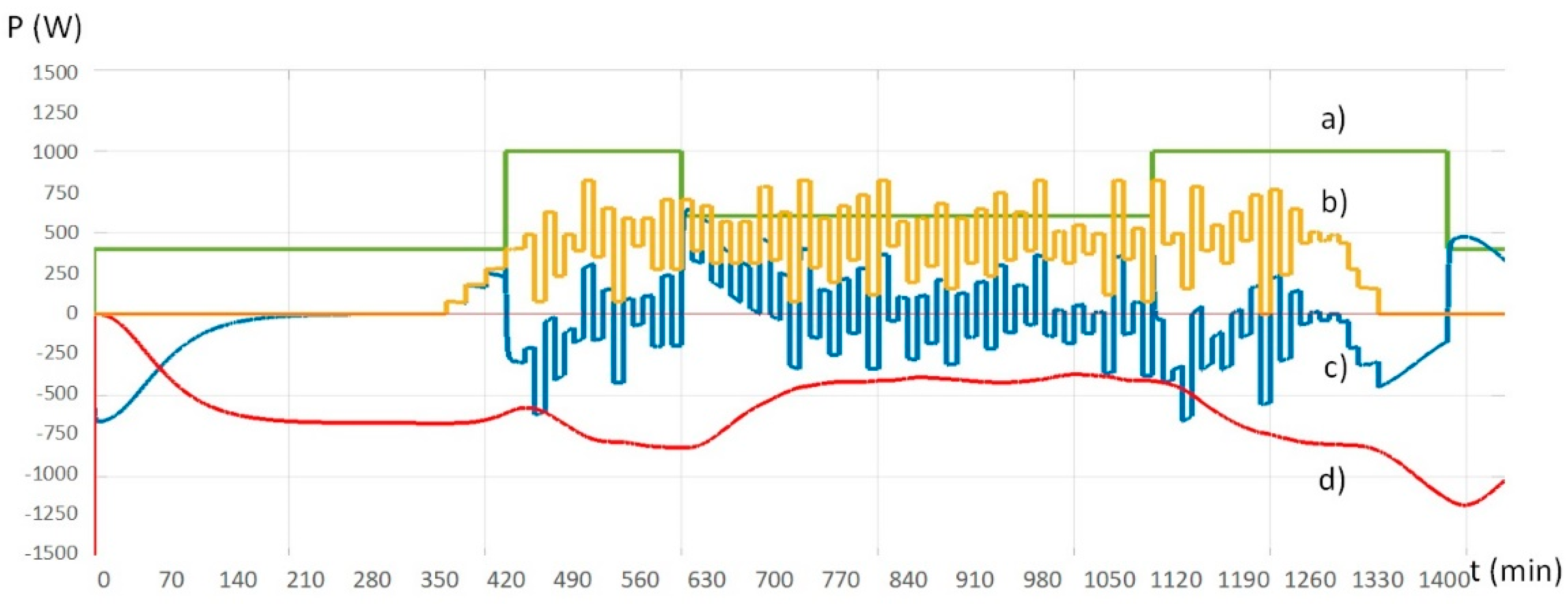
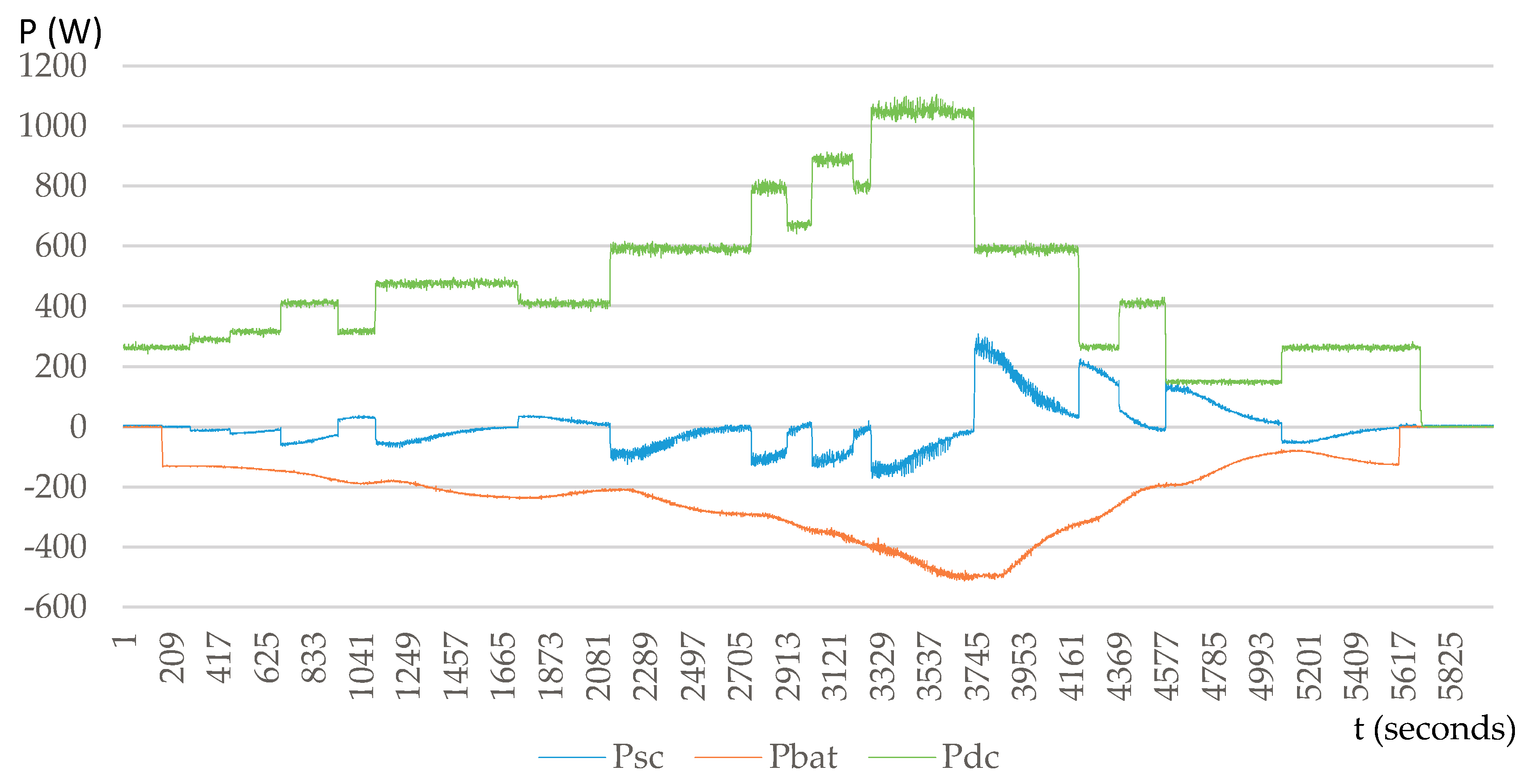
The main goal of these experiments is to study the interaction between the battery and the supercapacitor and validate the simulation results. The sequence of the experiment is the following: The programmable DC power supply modifies the voltage of the DC bus and, consequently, the power consumed by the passive load changes. The tested energy management strategy is configured so that half of the required power is provided by the ESS, and the rest of the power is provided by the programmable DC supply. The changes in the passive load consumption due to voltage variations change in turn the reference value for the ESS. These variations in the reference voltage of the programmable DC power supply allow to observe the interactions between the battery and the supercapacitor of the ESS, and the time responses of these systems. The influence of the low pass filter linear coefficient value will be confirmed.

6.3. Results

The two practical experiments consist in step variations of the consumed power and the reactions of the ESS. The combination of small and big increased and decreased steps helps to show the dynamics of the considered control scheme. In the first experiment, plotted in Figure 21, a damping ratio ζ of the storage system filter equal to 0.1 was used.
In the second experiment, plotted in Figure 22, the damping ratio ζ of the storage system filter was set to 0.25.
Higher values of the damping ratio ζ of the storage system filter increase its time response. This helps to absorb the power fluctuations by the supercapacitor, which is not sensitive to this, unlike the battery. As can be seen in Figure 21 and Figure 22, the filter with the highest value of the linear coefficient allows the supercapacitor to absorb almost the totality of the power fluctuations. Therefore, the profile of the power stored in the battery is smooth. This allows to smooth out the variation of the discharging current of the battery, reducing, therefore, the microcycle operation in the batteries.
Short-term power variations have negligible influences on the discharging profile of the battery. In addition, it can be observed that sudden changes of the required power show good work implementation and operation of the applied control of the ESS. Consequently, the operation of the HRES with the supercapacitor and with the second order storage filter increases the durability and robustness of the HRES.

7. Conclusions

At the present time, the HRES starts to be more and more common, but is still associated with high cost and limited durability time. The weakest part of the HRES is the battery storage system, as its lifetime does not exceed five years in good operation conditions. Unsatisfactory operation conditions, such as microcycle operations, cause the premature ageing of the battery system and its failure before its nominal lifespan. In order to avoid this problem, the combination of batteries and supercapacitors storage systems in the HRES was investigated in this paper.
The supercapacitors are suitable for the fast variations of charged/discharged power with a high number of cycles. They barely suffer from degradation processes and have a high-power density, unlike the batteries, with a low power density and a limited number of cycles of charge/discharge.
The structure of the HRES, the models of its components and the operation control have been studied in this paper. The process of the HRES control in the case of the grid connection was also described.
Batteries and supercapacitors have been analyzed in detail, particularly the use of a low-pass filter of the second order which splits the reference signal for the batteries and supercapacitors in the storage system. Simulation and experimental results shown the influence of the coefficient of this filter on the battery storage operation, demonstrating that the value of the damping ratio ζ of the storage system filter can help to smooth the reference power of the battery. A higher value of this coefficient helps to absorb more efficiently the power fluctuations by the supercapacitors, and consequently to reduce the microcycle operation of the batteries, thereby improving the lifetime of the batteries.

Author Contributions

Conceptualization, J.A. Data curation, J.A. and P.R.-S. Funding acquisition, P.R.-S., M.A.-T. and G.L. Investigation, J.A. and P.R.-S. Writing, original draft, J.A. and P.R.-S. Writing, review and editing, M.A.-T., J.V. and G.L.

Funding

This work has been partially supported by the Ministry of Economy and Competitiveness of Spain and by the European Regional Development Fund under the research project ENE2015-71417-R (MINECO/FEDER, UE) and University of Paris-Est Doctoral School SIE.

Conflicts of Interest

The authors declare no conflict of interest.

References

  1. Cucchiella, F.; D’Adamo, I.; Gastaldi, M. Photovoltaic energy systems with battery storage for residential areas: An economic analysis. J. Clean. Prod. 2016, 131, 460–474. [Google Scholar] [CrossRef]
  2. Guerrero, J.M.; Loh, P.C.; Lee, T.; Chandorkar, M. Advanced control architectures for intelligent—Part II: Power quality, energy storage, and ac/dc microgrids. IEEE Trans. Ind. Electron. 2013, 60, 1263–1270. [Google Scholar] [CrossRef]
  3. Wang, P.; Liu, X.; Jin, C.; Loh, P.; Choo, F. A hybrid AC/DC micro-grid architecture, operation and control. In Proceedings of the 2011 IEEE Power and Energy Society General Meeting, Detroit, MI, USA, 24–28 July 2011; pp. 1–8. [Google Scholar]
  4. Bocklisch, T. Hybrid Energy Storage Systems for Renewable Energy Applications. Energy Procedia 2015, 73, 103–111. [Google Scholar] [CrossRef] [Green Version]
  5. Klingler, A.-L. Self-consumption with PV + Battery systems: A market diffusion model considering individual consumer behaviour and preferences. Appl. Energy 2017, 205, 1560–1570. [Google Scholar] [CrossRef]
  6. Veríssimo, R.; Lopes, R.A.; Martins, J.F. Energy storage systems to prevent distribution transformers overload with high NZEB penetration. In Proceedings of the IECON 2018—44th Annual Conference of the IEEE Industrial Electronics Society, Washington, DC, USA, 21–23 October 2018; IEEE: Piscataway, NJ, USA; pp. 6071–6076. [Google Scholar]
  7. De La Cruz, C.; Baptista Lema, M.; Del Toro, G.; Roncero-Sánchez, P. Storage integration with renewable energies: The case of concentration photovoltaic systems. In Handbook of Environmental Chemistry; Springer International Publishing: New York, NY, USA, 2014; Volume 34. [Google Scholar]
  8. Masaki, M.S.; Zhang, L.; Xia, X. A hierarchical predictive control for supercapacitor-retrofitted grid-connected hybrid renewable systems. Appl. Energy 2019, 242, 393–402. [Google Scholar] [CrossRef]
  9. Ruiz-Cortés, M.; González-Romera, E.; Lopes, R.A.; Romero-Cadaval, E.; Martins, J.F.; Milanés-Montero, M.I.; Barreto-González, F. Improved forecasting-based battery energy management strategy for prosumer systems. In Proceedings of the IECON 2018—44th Annual Conference of the IEEE Industrial Electronics Society IEEE, Washington, DC, 21–23 October 2018; pp. 6077–6082. [Google Scholar]
  10. Dougal, R.A.; Liu, S.; White, R.E. Power and life extension of battery-ultracapacitor hybrids. IEEE Trans. Compon. Packag. Technol. 2002, 25, 120–131. [Google Scholar] [CrossRef] [Green Version]
  11. Momayyezan, M.; Abeywardana, D.B.W.; Hredzak, B.; Agelidis, V.G. Integrated Reconfigurable Configuration for Battery/Ultracapacitor Hybrid Energy Storage Systems. IEEE Trans. Energy Convers. 2016, 31, 1583–1590. [Google Scholar] [CrossRef]
  12. Xiong, R.; Chen, H.; Wang, C.; Sun, F. Towards a smarter hybrid energy storage system based on battery and ultracapacitor—A critical review on topology and energy management. J. Clean. Prod. 2018, 202, 1228–1240. [Google Scholar] [CrossRef]
  13. Cao, J.; Emadi, A. A New Battery/UltraCapacitor Hybrid Energy Storage System for Electric, Hybrid, and Plug-In Hybrid Electric Vehicles. IEEE Trans. Power Electron. 2012, 27, 122–132. [Google Scholar]
  14. Liu, Y.; Chen, M.; Lu, S.; Chen, Y.; Li, Q. Optimized Sizing and Scheduling of Hybrid Energy Storage Systems for High-Speed Railway Traction Substations. Energies 2018, 11, 2199. [Google Scholar] [CrossRef]
  15. Roncero-Sánchez, P.; Parreño Torres, A.; Vázquez, J. Control Scheme of a Concentration Photovoltaic Plant with a Hybrid Energy Storage System Connected to the Grid. Energies 2018, 11, 301. [Google Scholar] [CrossRef]
  16. Novak, H.; Vašak, M.; Lešić, V. Hierarchical energy management of multi-train railway transport system with energy storages. In Proceedings of the 2016 IEEE International Conference on Intelligent Rail Transportation (ICIRT), Birmingham, UK, 23–25 August 2016; pp. 130–138. [Google Scholar]
  17. Hredzak, B.; Agelidis, V.G.; Jang, M. A Model Predictive Control System for a Hybrid Battery-Ultracapacitor Power Source. IEEE Trans. Power Electron. 2014, 29, 1469–1479. [Google Scholar] [CrossRef]
  18. Masaki, M.S.; Zhang, L.; Xia, X. Hierarchical Power Flow Control of a Grid-tied Photovoltaic Plant Using a Battery-Supercapacitor Energy Storage System. Renew. Energy Integr. Mini Microgrid 2018, 145, 32–37. [Google Scholar] [CrossRef]
  19. Kollimalla, S.K.; Ukil, A.; Gooi, H.B.; Manandhar, U.; Tummuru, N.R. Optimization of Charge/Discharge Rates of a Battery Using a Two-Stage Rate-Limit Control. IEEE Trans. Sustain. Energy 2017, 8, 516–529. [Google Scholar] [CrossRef]
  20. Tummuru, N.R.; Mishra, M.K.; Srinivas, S. Dynamic Energy Management of Renewable Grid Integrated Hybrid Energy Storage System. IEEE Trans. Ind. Electron. 2015, 62, 7728–7737. [Google Scholar] [CrossRef]
  21. Hu, S.; Liang, Z.; He, X. Ultracapacitor-Battery Hybrid Energy Storage System Based on the Asymmetric Bidirectional Z -Source Topology for EV. IEEE Trans. Power Electron. 2016, 31, 7489–7498. [Google Scholar] [CrossRef]
  22. Pena-Alzola, R.; Liserre, M.; Blaabjerg, F.; Yang, Y. Robust design of LCL-filters for active damping in grid converters. In Proceedings of the IECON 2013—39th Annual Conference of the IEEE, Vienna, Austria, 10–13 November 2013; IEEE: Piscataway, NJ, USA; pp. 1248–1253. [Google Scholar]
  23. Li, Y.; Vilathgamuwa, D.M.; Loh, P.C. Design, Analysis, and Real-Time Testing of a Controller for Multibus Microgrid System. IEEE Trans. Power Electron. 2004, 19, 1195–1204. [Google Scholar] [CrossRef]
  24. Zhou, H.; Bhattacharya, T.; Tran, D.; Siew, T.S.T.; Khambadkone, A.M. Composite Energy Storage System Involving Battery and Ultracapacitor With Dynamic Energy Management in Microgrid Applications. IEEE Trans. Power Electron. 2011, 26, 923–930. [Google Scholar] [CrossRef]
  25. Del Toro García, X.; Roncero-Sánchez, P.; Parreño, A.; Feliu, V. Ultracapacitor-based storage: Modelling, power conversion and energy considerations. In Proceedings of the 2010 IEEE International Symposium on Industrial Electronics, Bari, Italy, 4–7 July 2010; pp. 2493–2498. [Google Scholar]
  26. Adhikari, S.; Lei, Z.; Peng, W.; Tang, Y. A battery/supercapacitor hybrid energy storage system for DC microgrids. In Proceedings of the 2016 IEEE 8th International Power Electronics and Motion Control Conference (IPEMC-ECCE Asia), Hefei, China, 22–26 May 2016; pp. 1747–1753. [Google Scholar]
  27. Guerrero, M.A.; Romero, E.; Barrero, F.; Milanés, M.I.; González, E. Supercapacitors: Alternative Energy Storage Systems. Przeglad Elektrotechniczny 2009, 85, 188–195. [Google Scholar]
  28. Siemaszko, D.; Rufer, A. Double-Frame Current Control with a Multivariable PI Controller and Power Compensation for Weak Unbalanced Networks. In Proceedings of the CAS—CERN Accelerator School: Power Converters, Baden, Switzerland, 7–14 May 2014. [Google Scholar]
  29. Kant, K.; Singh, B.; Kalla, U. Single voltage measurement based control algorithm for voltage source converter. In Proceedings of the 2016 IEEE 7th Power India International Conference (PIICON), Bikaner, India, 25–27 November 2016; pp. 1–4. [Google Scholar]
  30. Arkhangelski, J.; Abdou-Tankari, M.; Lefebvre, G.; Roncero-Sánchez, P.; Molina-Martínez, E.J. Grid Synchronization and Injection Control of HRES Power Generation. In Proceedings of the 7th International Conference on Renewable Energy Research and Applications (ICRERA), Paris, France, 14–17 October 2018; pp. 1276–1281. [Google Scholar]
  31. Roncero-Sanchez, P.; del Toro Garcia, X.; Torres, A.P.; Feliu, V. Fundamental Positive-and Negative-Sequence Estimator for Grid Synchronization Under Highly Disturbed Operating Conditions. IEEE Trans. Power Electron. 2013, 28, 3733–3746. [Google Scholar] [CrossRef]
  32. Freijedo, F.D.; Doval-Gandoy, J.; LÓpez, Ó.; Acha, E. A Generic Open-Loop Algorithm for Three-Phase Grid Voltage/Current Synchronization with Particular Reference to Phase, Frequency, and Amplitude Estimation. IEEE Trans. Power Electron. 2009, 24, 94–107. [Google Scholar] [CrossRef]
  33. Gilani, S.O.; Ilyas, Y.; Jamil, M. Power line noise removal from ECG signal using notch, band stop and adaptive filters. In Proceedings of the 2018 International Conference on Electronics, Information, and Communication (ICEIC), Honolulu, HI, USA, 24–27 January 2018; pp. 1–4. [Google Scholar]
  34. Apetrei, V.; Filote, C.; Graur, A. Comparative harmonic analysis of power-quality indices in three-phase power systems. In Proceedings of the 2014 International Conference on Optimization of Electrical and Electronic Equipment (OPTIM), Bran, Romania, 22–24 May 2014; IEEE: Piscataway, NJ, USA; pp. 136–143. [Google Scholar]
  35. Roncero-Sánchez, P.L.; Feliu-Batlle, V.; García-Cerrada, A.; García-González, P. Repetitive-control system for harmonic elimination in three-phase voltage-Source inverters. IFAC Proc. Vol. 2005, 38, 430–435. [Google Scholar] [CrossRef]
  36. Roncero-Sánchez, P.; del Toro Garcia, X.; Parreño-Torres, A.; Feliu, V. Robust Frequency-Estimation Method for Distorted and Imbalanced Three-Phase Systems Using Discrete Filters. IEEE Trans. Power Electron. 2011, 26, 1089–1101. [Google Scholar] [CrossRef]
  37. Roncero-Sànchez, P.; Acha, E. Design of a Control Scheme for Distribution Static Synchronous Compensators with Power-Quality Improvement Capability. Energies 2014, 7, 2476–2497. [Google Scholar] [CrossRef] [Green Version]
  38. Santiprapan, P.; Areerak, K.-L.; Areerak, K.-N. Mathematical Model and Control Strategy on DQ Frame for Shunt Active Power Filters. World Acad. Sci. Eng. Technol. 2011, 5, 9. [Google Scholar]
  39. Zammit, D.; Staines, C.S.; Apap, M. Comparison between PI and PR Current Controllers in Grid Connected PV Inverters. Int. J. Electr. Comput. Eng. 2014, 8, 6. [Google Scholar]
  40. Zhang, N.; Tang, H.; Yao, C. A Systematic Method for Designing a PR Controller and Active Damping of the LCL Filter for Single-Phase Grid-Connected PV Inverters. Energies 2014, 7, 3934–3954. [Google Scholar] [CrossRef]
  41. Teodorescu, R.; Blaabjerg, F.; Liserre, M.; Loh, P.C. Proportional-resonant controllers and filters for grid-connected voltage-source converters. IEE Proc. Electr. Power Appl. 2006, 153, 750. [Google Scholar] [CrossRef]
  42. Blahnik, V.; Peroutka, Z.; Talla, J.; Matuljak, I. Low ripple current source based on resonant controllers. In Proceedings of the IECON 2013—39th Annual Conference of the IEEE Industrial Electronics Society, Vienna, Austria, 10–13 November 2013; pp. 967–972. [Google Scholar]
  43. Rodriguez, P.; Luna, A.; Candela, I.; Mujal, R.; Teodorescu, R.; Blaabjerg, F. Multiresonant Frequency-Locked Loop for Grid Synchronization of Power Converters Under Distorted Grid Conditions. IEEE Trans. Ind. Electron. 2011, 58, 127–138. [Google Scholar] [CrossRef]
  44. Errouissi, R.; Al-Durra, A.; Muyeen, S.M. Design and Implementation of a Nonlinear PI Predictive Controller for a Grid-Tied Photovoltaic Inverter. IEEE Trans. Ind. Electron. 2017, 64, 1241–1250. [Google Scholar] [CrossRef]
  45. Bierhoff, M.; Brandenburg, H.; Fuchs, F.W. An Analysis on Switching Loss Optimized PWM Strategies for Three Phase PWM Voltage Source Converters. In Proceedings of the IECON 2007—33rd Annual Conference of the IEEE Industrial Electronics Society, Taipei, Taiwan, 5–8 November 2007; IEEE: Piscataway, NJ, USA, 2007; pp. 1512–1517. [Google Scholar]
  46. Séguier, G.; Labrique, F. Power Electronic Converters: DC-AC Conversion; Springer: Berlin, Germany, 1993; ISBN 978-3-642-50324-5. [Google Scholar]
  47. Bentley, J.H. A Programmed Review for Electrical Engineering; Springer Netherlands: Dordrecht, The Netherlands, 1985; ISBN 978-94-009-4860-0. [Google Scholar]
  48. De Beer, B.; Rix, A.J. Network strengthening using storage support: A case for increasing remote generation. In Proceedings of the 2017 IEEE AFRICON, Cape Town, South Africa, 18–20 September 2017; pp. 1173–1178. [Google Scholar]
  49. Zhang, Z.; Li, R.; Zhao, C.; Li, F. Cross-characterization of PV and Sunshine Profiles Based on Hierarchical Classification. Energy Procedia 2016, 103, 15–21. [Google Scholar] [CrossRef]
  50. Niimura, T.; Ozawa, K.; Yamashita, D.; Yoshimi, K.; Osawa, M. Profiling residential PV output based on weekly weather forecast for home energy management system. In Proceedings of the 2012 IEEE Power and Energy Society General Meeting, San Diego, CA, USA, 22–26 July 2012; IEEE: Piscataway, NJ, USA; pp. 1–5. [Google Scholar]
  51. Ting, T.O.; Man, K.L.; Guan, S.-U.; Seon, J.K.; Jeong, T.T.; Wong, P.W.H. Maximum Power Point Tracking (MPPT) via Weightless Swarm Algorithm (WSA) on cloudy days. In Proceedings of the 2012 IEEE Asia Pacific Conference on Circuits and Systems, Kaohsiung, Taiwan, 2–5 December 2012; IEEE: Piscataway, NJ, USA; pp. 336–339. [Google Scholar]
  52. Vasudevarao, B.V.M.; Stifter, M.; Zehetbauer, P. Methodology for creating composite standard load profiles based on real load profile analysis. In Proceedings of the 2016 IEEE PES Innovative Smart Grid Technologies Conference Europe (ISGT-Europe), Ljubljana, Slovenia, 9–12 October 2016; IEEE: Piscataway, NJ, USA; pp. 1–6. [Google Scholar]
  53. Ropeter, C.; Wenzl, H.; Beck, H. IEE: Impact of Microcycles on Batteries Microcycles and Batteries_publ-EVS18.DOC 1/12 The Impact of Microcycles on Batteries in Different Applications. In Proceedings of the 18th Electric Vehicle Symposium, Berlin, Germany, 20–24 October 2001. [Google Scholar]
  54. Ruetschi, P. Aging mechanisms and service life of lead–acid batteries. J. Power Sources 2004, 127, 33–44. [Google Scholar] [CrossRef]
Figure 1. General structure of the HRES.
Energies 12 02776 g001
Figure 2. Detailed scheme of the Hybrid Renewable Energy System (HRES) for the injection of photovoltaic energy into the grid.
Energies 12 02776 g002
Figure 3. Closed-loop scheme to control the active power exchanged with the three-phase section of the HRES.
Energies 12 02776 g003
Figure 4. Proposed control scheme of the HRES storage system with the inclusion of a low-pass filter.
Energies 12 02776 g004
Figure 5. Detailed view of the control system of the VSC of HRES.
Energies 12 02776 g005
Figure 6. Scheme of the “Normalization” subsystem.
Energies 12 02776 g006
Figure 7. Scheme of the “Current control with harmonic compensation” subsystem.
Energies 12 02776 g007
Figure 8. Scheme of the “Inverter loss reduction” subsystem.
Energies 12 02776 g008
Figure 9. The graph of optimization signals: (a) the fundamental sinusoid, (b) the third harmonic of fundamental sinusoid, (c) the optimized reference sinusoid.
Energies 12 02776 g009
Figure 10. Block diagram of the power balance system of the HRES.
Energies 12 02776 g010
Figure 11. The graph of simulation process input: (a) the PV plant production profile for a sunny day (yellow), (b) the consumer request profile (green), and (c) the PV plant production profile for a cloudy day (red).
Energies 12 02776 g011
Figure 12. Simulation process for sunny day conditions. Storage system filter with damping ratio ζ = 0.1 : (a) the PV plant production, (b) the power required by the consumer, (c) the battery storage power and (d) the supercapacitor power.
Energies 12 02776 g012
Figure 13. Simulation process for sunny day conditions. Storage system filter with damping ratio ζ = 0.25 : (a) the PV plant production, (b) the power required by the consumer, (c) the battery storage power and (d) the supercapacitor power.
Energies 12 02776 g013
Figure 14. Simulation process for sunny day conditions. Storage system filter with damping ratio ζ = 0.5 : (a) the PV plant production, (b) the power required by the consumer, (c) the battery storage power and (d) the supercapacitor power.
Energies 12 02776 g014
Figure 15. Simulation process for cloudy day conditions. Storage system filter with damping ratio ζ = 0.1: (a) the PV plant production, (b) the power required by the consumer, (c) the battery storage power and (d) the supercapacitor power.
Energies 12 02776 g015
Figure 16. Simulation process for cloudy day conditions. Storage system filter with damping ratio ζ = 0.25: (a) the PV plant production, (b) the power required by the consumer, (c) the battery storage power and (d) the supercapacitor power.
Energies 12 02776 g016
Figure 17. Simulation process for cloudy day conditions. Storage system filter with damping ratio ζ = 0.5: (a) the PV plant production, (b) the power required by the consumer, (c) the battery storage power and (d) the supercapacitor power.
Energies 12 02776 g017
Figure 18. Battery and supercapacitor storage system DC/DC converters.
Energies 12 02776 g018
Figure 19. Supercapacitors (centre) and CINERGIA Battery Emulator (left).
Energies 12 02776 g019
Figure 20. dSPACE1103 platform (centre) and programmable DC power supply AMREL (top left).
Energies 12 02776 g020
Figure 21. Graphics of the first experiment: damping ratio ζ = 0.1 .
Energies 12 02776 g021
Figure 22. Graphics of the second experiment: damping ratio ζ = 0.25 .
Energies 12 02776 g022
Table 1. Parameters of the battery storage system.
CoefficientValueDescription
R b s 2.4 × 10⁻² Ω Series resistance of the battery
R p s 3.6 × 10⁻³ ΩParallel resistance of the battery
C b p 10.5 FParallel capacitance of the battery
n b a t 12Number of batteries in series
R b a t 6.3 × 10⁻¹ ΩResistance of the inductive filter of the battery
L b a t 7.21 × 10⁻³ HInductance of the inductive filter of the battery
K i b a t 1802Integral gain of battery current control
K p b a t −7.83Proportional gain of battery current control
V b a t 100 VOpen-circuit voltage of the battery system
Table 2. Parameters of the SC storage system.
CoefficientValueDescription
C u c 47 FCapacitance of the supercapacitor
R u c 1.8 × 10⁻¹ ΩResistance of the inductive filter of the supercapacitor
L u c 1.1 × 10⁻³ HInductance of the inductive filter of the supercapacitor
K i u c 275Integral gain of supercapacitor current control
Table 3. Parameters of the DC and three-phase part of the HRES.
CoefficientValueDescription
C d c 1.36 × 10⁻³ FCapacitance of the DC capacitor
R g c f 6.96 × 10⁻¹ ΩResistance of the grid connected filter
L g c f 7.1 × 10⁻³ HInductance of the grid connected inductive filter
K i 3 p h s 7100Integral gain of HRES current control
K p 3 p h s −14.896Proportional gain of HRES current control
H s t ( s ) ω n 2 s 2 + 2 ζ ω n + ω n 2 Transfer function of low-pass storage system filter, where ω n = 4 , ζ = 0.1 , 0.25 , 0.5
V d c 700 VReference of the DC-link voltage

