Article

Investigation on the Frictional Performance of Surface Textured Ring-Deformed Liner Conjunction in Internal Combustion Engines

1
School of Mechanical and Precision Instrument Engineering, Xi’an University of Technology, Xi’an 710048, China
2
State Key Laboratory of Digital Manufacturing Equipment and Technology, Huazhong University of Science and Technology, Wuhan 430074, China
3
School of Printing, Packaging Engineering and Digital Media Technology, Xi’an University of Technology, Xi’an 710048, China
4
College of Engineering, Michigan State University, East Lansing, MI 48824, USA
*
Authors to whom correspondence should be addressed.
Energies 2019, 12(14), 2761; https://doi.org/10.3390/en12142761
Submission received: 9 June 2019 / Revised: 11 July 2019 / Accepted: 15 July 2019 / Published: 18 July 2019
(This article belongs to the Section F: Electrical Engineering)

Abstract

:
In internal combustion engines (ICEs), the frictional performance of ring-liner conjunction (RLC) has drawn special attention because it greatly affects the fuel efficiency of the engines. In recent years, surface texture (i.e., micro dimples or grooves) has emerged as a promising approach to improve the frictional performance of RLC. However, most current studies on surface textured RLC were conducted by assuming that the liner was ideally circular and the lubrication condition was either fully flooded or starved. In this study, to evaluate the frictional characteristics of an RLC with surface texture on the ring, a numerical model of lubrication is presented by considering the liner deformation, as well as the coexistence of the fully flooded and staved lubrication conditions in an engine cycle. On this basis, the frictional properties of a surface textured RLC are analyzed, and the impacts of the liner deformation and temperature on the friction-reducing effect of the surface texture are also evaluated. The results show that the surface texture on the ring can effectively reduce the power dissipation and friction dissipation of an RLC, and the reductions vary with the liner temperature and deformation. Large reductions in the power dissipation and friction dissipation of an RLC are obtained when the liner temperature is low or the liner deformation is small.

1. Introduction

In recent years, surface texture has been regarded as an effective approach to improve the frictional performance of the ring-liner conjunction (RLC) in internal combustion engines (ICEs) [1,2,3,4]. However, for the RLC in ICEs, actual working conditions are very complex and greatly affect frictional performance [5,6]. Therefore, to understand the friction-reducing mechanism of the surface texture on the ring/liner more deeply, the investigation into the frictional characteristics of surface textured RLC under complex working conditions has attracted more and more attention.
During the working process of an RLC, hydrodynamic and mixed regimes of lubrication usually coexist in an engine cycle [5,7]. Hence, the hydrodynamic and mixed regimes of lubrication in the engine cycle of an RLC must be considered. Etsion et al. [8,9] conducted some research works on the friction-reducing effect of the dimple textured ring. The partially dimple textured ring was observed to have excellent frictional properties under the hydrodynamic lubrication regime. Caciu et al. [10] assessed the frictional characteristics of the dimple/groove textured liner. Optimal frictional properties were observed when a suitable shape and distribution were chosen for the dimple/groove. Noutary et al. [11] analyzed the oil film pressure of an RLC with different groove shapes, depths, and densities by using a multigrid code method. Groove depth and density were observed to have great influence on load-carrying capacity. Ezhilmaran et al. [12] textured laser dimples on the ring by using YAG (yttrium aluminum garnet) system. The frictional properties and oil film distribution in a textured RLC were studied experimentally and theoretically. However, these works [8,9,10,11,12] were mainly focused on the frictional properties of the textured RLC under the hydrodynamic regime of lubrication. The frictional properties of the textured RLC under the mixed regime of lubrication need to be further understood.
Usman et al. [13] developed a 2D mathematical model to simulate the frictional characteristics of the textured RLC under the mixed regime of lubrication by considering the realistic rheology properties of lubricant. The influence of surface texture on the frictional behaviors of an RLC was studied under warm operation conditions. Morris et al. [14] presented a combined model to predict the frictional behaviors of a laser textured RLC at piston top dead center (the regime of lubrication was mixed). The friction reduction of the RLC after surface texturing was negligible when the depth of surface texture was small. Yin et al. [15] assessed the mixed lubrication behaviors of a textured RLC under different combustion modes. The combustion mode showed a significant effect on lubrication performance. Liu et al. [16] and Söderfjäll et al. [17] proposed a mass conservative lubrication model for a dimple textured liner with a consideration of asperity contact under the mixed regime of lubrication. Based on the model, the impact of dimple geometry on the friction and power dissipation of an RLC was studied. In these works [13,14,15,16,17], the lubrication condition of the RLC was assumed to be fully flooded, and an isothermal condition was also considered. By considering that the oil film thermal effect caused by friction and the prevalent starved lubrication condition in an RLC, Meng and his coworkers [18,19,20] studied the effects of surface texture on the frictional characteristics of an RLC. Their results showed that surface texture can reduce the friction of an RLC significantly, even if the lubrication condition was starved. In the works of Meng et al. [18,19,20], an ideal circular liner was considered to evaluate the frictional characteristics of a surface textured RLC.
It is clear that a liner is not ideally circular, and two different conditions of lubrication (i.e., fully flooded and starved) usually coexist in an RLC engine cycle [21,22,23]. This is because liner deformation at assembly and service stages is inevitable [24], and the lubricant supplied to the ring is time-varying and usually insufficient at some points of the engine cycle [25]. Therefore, this study provides a comprehensive mathematical model to analyze the frictional characteristics of a groove textured RLC by considering liner deformation and the coexistence of the two different lubrication conditions in an engine cycle. Based on the model, the frictional characteristics of a groove textured RLC were analyzed for different liner deformations. Furthermore, different liner temperatures were also considered to evaluate the friction-reducing effect of ring grooves because liner temperature has great influence on lubricant viscosity [26], and different values of lubricant viscosity will result in different frictional behaviors.

2. Mathematical Modeling

2.1. Geometrical Modeling

Micro grooves are considered to be textured at the both ends of a ring because of its significant friction-reducing effect [13]. Figure 1 and Table 1 show the schematic diagram and geometry parameters of an RLC with micro grooves. To describe the geometry and distribution of the grooves, three dimensionless parameters are defined and written as [13]:
χ   =   b t / b ,
s   =   r g / r c ,
ε   =   h g / r g ,
where χ is the area ratio of groove and χ = 0.6 is adopted in the analysis [13]. bt is width of textured zone in the axial direction, b is the width of ring, s is the area density of groove, and ε is the depth-to-width ratio of groove. According to previous research works [13,16], small values of the area density s (i.e., s = 0.25) and depth-to-width ε (i.e., ε = 0.1) were adopted in the current study to maximally improve the frictional characteristics. The corresponding dimensional width of groove rg, width between two adjacent grooves rc, and maximum depth of groove hg were 12.5, 50, and 1.25 μm respectively.
In this study, liner deformation was considered. To describe the radius variation of the deformed liner from its ideal circular shape ΔRcir, a Fourier series was used. The Fourier series can be written as follows [27,28]:
Δ R cir   =   n = 0 N [ A n cos ( n φ ) + B n sin ( n φ ) ] ,
To simplify the calculation, Equation (4) can be expressed as follows [28]:
Δ R cir   =   n = 0 N { Δ c n 2 cos [ n ( φ φ n ) ] } ,
with
Δ c n   =   2 A n 2 + B n 2 ,
φ n = 1 n arctan B n A n ,
where n is the order of liner deformation, N is the maximum order of liner deformation, φ is the angular position in the circumferential direction, φ n is the angle of maximum liner deformation in the circumferential direction for the order n, Δcn is the maximum liner deformation for the order n, and An and Bn are the Fourier coefficients for the order n.
Therefore, the variation of liner radius from its inscribed circle ΔR can be written as [21,28,29]:
Δ R =   Δ R cir Δ R min ,
where ΔRmin is the minimum variation in the liner radius.
In generally, ΔRcir can be modeled accurately by using a Fourier series with first few orders (i.e., n = 0, 1, 2, 3, 4 or N = 4) [27]. However, under working conditions, due to tension force and backpressure, the ring also elastically deforms to accommodate the radial radius variation of the liner when the liner is deformed, and the clearance between the ring and liner caused by the liner deformation after considering the elastic deformation of ring is mainly the outcome of the liner deformation with n = 4 [21]. Therefore, only n = 4 was considered in this and previous studies [21,25,28,29,30]. Figure 2 shows the deformed liner with n = 4.
It should be noted that the maximum liner deformation Δcn (or the values of the Fourier coefficients An and Bn) must be known in advance to model the liner deformation. Generally, the values of An and Bn can be obtained from a Fourier analysis on the measured profile of the deformed liner or on the simulated profile of the deformed liner (e.g., finite element simulation) [27]. However, the measurement and finite element simulation on the deformed liner profile is relatively complex and time consuming [27,28]. Furthermore, according to the work of Zhu et al. [31], for the liner deformation with n = 4, there is a small variation of the profile in the axial direction under some conditions. Therefore, in the simulation of liner deformation by using the Fourier series, it is usually assumed that the profile shape of the deformed liner remains the same in the axial direction for analysis convenience and time saving [22,25,29]. Hence, the profile of the deformed liner can be modeled by a Fourier series with a given value of Δcn [21,25,28,29,30]. In this study, according to the previous works [28,30], Δcn with a maximum value of 30 μm was considered for n = 4.
In general, ring elastic deformation reduces the clearance between the ring and liner caused by liner deformation. Therefore, a clearance in the RLC caused by a 4th order deformation of liner hliner can be expressed as [21,25,29]:
h liner =   Δ R | n = 4 Δ δ
where Δδ is the elastic deformation of the ring when the order n is 4, and it can be written as [25,29]:
Δ δ =   3 ( F t + F bp ) r 2 ( 2 r a r ) 2 225 E 1 ba r 3
where ar is the axial thickness of ring, Ft and Fbp are the tension force and back pressure of ring, E1 represents the Young’s modulus of ring, and r is the nominal liner radius.

2.2. Governing Equation

For the groove textured RLC, the average Reynolds equation and the JFO (Jacoboson–Floberg–Olsson) cavitation boundary condition are combined to analyze frictional behaviors. It is written as follows [32]:
x ( ϕ x ρ h 3 μ p x ) + y ( ϕ y ρ h 3 μ p y ) = 6 U ϕ c [ ( 1 ε ) ρ h ] x + 6 U σ [ ( 1 ε ) ρ ϕ s ] x + 12 ϕ c [ ( 1 ε ) ρ h ] t
with
{ p > p c   ε = 0 ε > 0   p = p c 0 ε 1
where ρ is the density of lubricant, μ is the lubricant viscosity, p is the lubricant pressure, t is the time, σ is the composite roughness of the RLC, U is the ring velocity, and h is the thickness of lubricant between the groove textured ring and liner. ε is the cavity fraction, and more discussion on the cavity fraction ε is provided in the work of Gu et al. [32]. pc is the cavity pressure, and it was assumed to be zero according to the reported works [2,20,23]. ϕ x and ϕ y are the pressure flow coefficients in the x and y directions, ϕ s and ϕ c are the coefficients of shear flow and contact flow; they can be calculated by using the classic P and C (Patir and Cheng) method [33,34] and W and Z (Wu and Zheng) method [35], respectively. These methods have been widely used in the simulation of RLCs with rough surfaces because they have the advantages of low cost in computation time and easy realization [20,36]. According to the P and C method and the W and Z method, the pressure flow, shear flow, and contact flow coefficients can be written as follows:
ϕ x = 1 0.9 e 0.56 λ   if   λ > 0.5
ϕ y = 1 0 . 9 e 0 . 56 λ   if   λ > 0 . 5
ϕ s = { 1.899 λ 0.98 ( σ 1 2 / σ 2 σ 2 2 / σ 2 ) e ( 0.92 λ + 0.05 λ 2 )   if   λ 5 1.126 ( σ 1 2 / σ 2 σ 2 2 / σ 2 ) e 0.25 λ   if   λ > 5
ϕ c = { e 0.6912 + 0.782 λ 0.304 λ 2 + 0.0401 λ 3   if   0 λ < 3 1   if   λ 3
with
σ = σ 1 2 + σ 2 2
λ = h / σ
where σ1 and σ2 are the surface roughness of ring and liner and λ is the ratio of lubricant thickness.
The thickness of lubricant between the groove textured ring and liner h can be written as follows:
h   =   h 0 + h groove + h liner + h ring
where h0 is the minimum clearance in the RLC, hgroove is the clearance caused by the groove, hring is the clearance related to the ring profile, and their expressions have been given in the reported works [3,16,25].

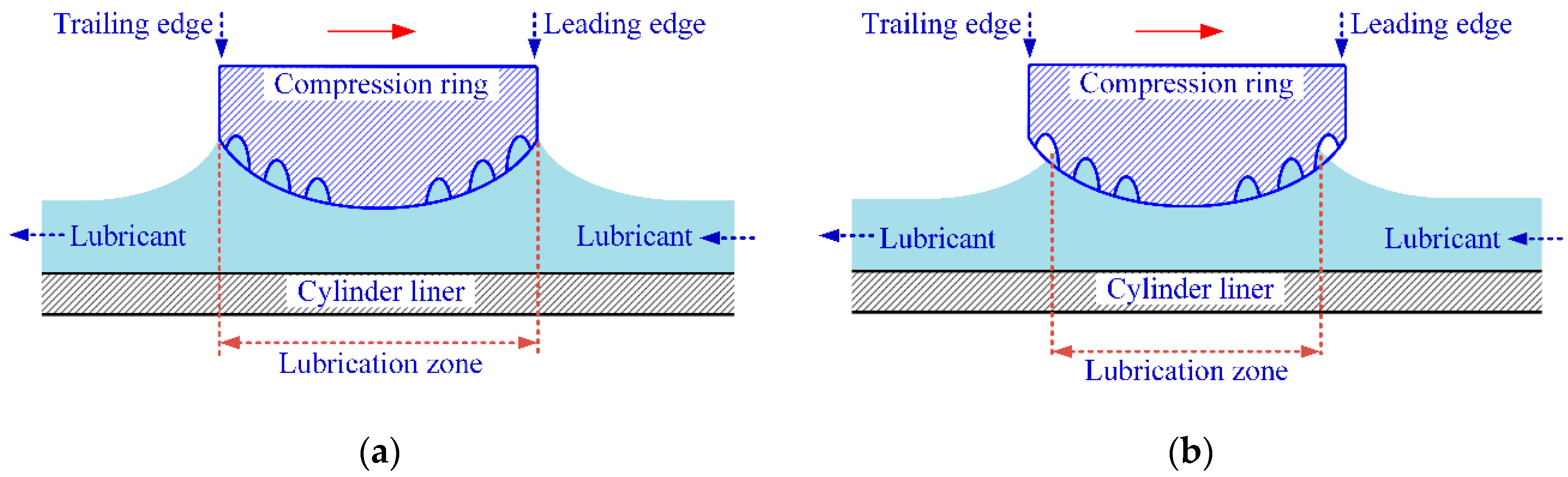
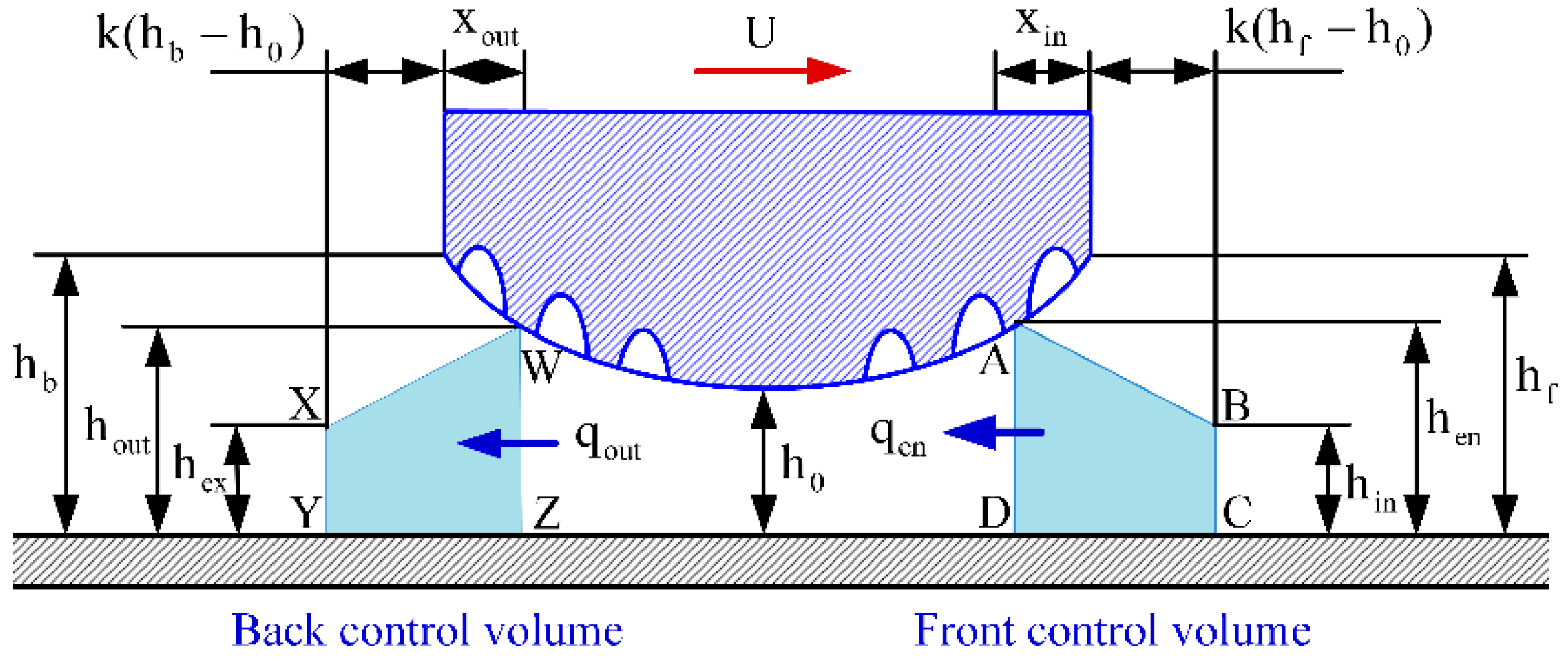
2.3. Lubrication Condition

Besides the fully flooded condition of lubrication, the starved condition of lubrication can be also observed at some crank angles in the engine cycle because the lubricant supplied to the RLC is usually insufficient [18,19]. Figure 3 shows the different conditions of the lubrication for the RLC. It should be noted that different lubrication conditions mean different boundary positions of the lubrication zone. Therefore, in order to solve the instant boundary positions (i.e., inlet position and outlet position) and then determine the instant lubrication condition, an oil transport model has been proposed, as shown in Figure 4. In Figure 4, two control volumes at the inlet and outlet of lubrication zone (i.e., front control volume and back control volume) are presented. For the front control volume, the average inflow rate of lubricant qin_ave and the average outflow rate of lubricant qen_ave within a time step Δt can be expressed as:
q in _ ave   =   Uh in + U 0 h in 0 2
q en _ ave   =   q en + q en 0 2
where hin is the lubricant entry height, superscript 0 represents the variables at the previous moment, and qen is the outflow rate of lubricant for the front control volume [18].
It should be noticed that the lubricant which flows into the front control volume is usually less than the lubricant which flows out of the front control volume [23]. Hence, the flow rate of lubricant in the front control volume changes within a time step Δt. The average variation of the lubricant flow rate in the front control volume qfront_ave can be written as [23]:
q front _ ave = ( V ABCD V A 0 B 0 C 0 D 0 ) Δ t
where VABCD is the area for the front control volume. It can be given by:
V ABCD = h in + h en 2 [ k ( h f h 0 ) + x in ]
where hen and xin are the inlet clearance and width, k is the aspect ratio, and hf represents the clearance at the leading edge of ring.
According to the principle of flow conservation, a flow balance equation should be satisfied for the front control volume [37]. The flow balance equation is given as:
q in _ ave   q en _ ave = q front _ ave
By submitting Equations (20)~(22) into Equation (24), the following expression can be obtained.
( Uh in + U 0 h in 0 ) ( q en + q en 0 ) 2 Δ t   = V ABCD V A 0 B 0 C 0 D 0
For the back control volume, a similar flow balance equation can be also written as follows:
q out _ ave   q ex _ ave = q back _ ave
where qout_ave and qex_ave are the average inflow rate and average outflow rate of lubricant for the back control volume, qback_ave is the average variation of lubricant flow rate in the back control volume, and their expressions can be written as follows:
q out _ ave   =   q out + q out 0 2
q ex _ ave   =   Uh ex + U 0 h ex 0 2
q back _ ave   =   V WXYZ V W 0 X 0 Y 0 Z 0 Δ t
where qout and hex are the inflow rate and exit height of lubricant for the back control volume. VWXYZ is the area of the back control volume, and its expression is written as [37]:
V WXYZ = { k ( h b h 0 ) ( h b + h ex 2 ) if   h ex h 0 k ( h out h ex ) ( h out + h ex 2 )   if   h 0 10 h ex < h 0 [ k ( h b h 0 ) + x out ] h ex + k 2 ( h out h 0 10 ) 2   if   h ex < h 0 10
where hout and xout are the outlet clearance and outlet width and hb represents the clearance at the trailing edge of ring.
By submitting Equations (27)~(29) into Equation (26), the following expression can be obtained.
( q out + q out 0 ) ( Uh ex + U 0 h ex 0 ) 2 Δ t   = V WXYZ V W 0 X 0 Y 0 Z 0
By solving Equations (25) and (31), the inlet width xin and outlet width xout can be obtained, and the instant lubrication condition can be determined. In details, the lubrication condition is fully flooded when xin and xout are zero. Otherwise, the lubrication condition is starved. Furthermore, the boundary condition of the governing equation (i.e., Equation (11)) can be also given as follows:
{ p | x = b 2 x i n = p in p | x = b 2 + x out = p out
where pin and pout are the pressures of lubricant at the boundary positions of the lubrication zone. On the intake stroke and power stroke, pin is the gas pressure under the ring and pout is the pressure in cylinder. However, on the compression stroke and exhaust stroke, pin is the pressure in cylinder and pout is the gas pressure under the ring.

2.4. Thermal Effect of Lubricant

During the working process of the RLC, the generated friction heat will raise the lubricant temperature. The temperature rise of the lubricant changes the density and viscosity, and it then greatly affects the frictional characteristics of the RLC. To determine the temperature rise of the lubricant, an analytical thermal model [38] was used in the current study. According to the model, the temperature of lubricant Toil can be written as follows:
T oil   =   R liner R oil T ring + R liner R ring T 0 + R ring R oil T liner + R liner R ring R oil Q R ring R oil + R liner R oil + R liner R ring
where Rliner is the thermal conductive flow barrier of the liner, Rring is the thermal conductive flow barrier of the ring, and Roil is the thermal conductive flow barrier of the lubricant. Tring and Tliner are the temperatures on the ring surface and liner surface. T0 is the lubricant temperature at the inlet of lubrication zone, Q is the flow rate of friction heat, and the expressions of T0 and Q can be written as [38]:
T 0   =   T liner U liner + T ring U U liner + U
Q   =   | f total U |
where Uliner is velocity of the liner and ftotal is the total friction force of the RLC.
After calculating the lubricant temperature Toil (Equation (33)) and pressure p (Equation (11)), the lubricant density ρ and viscosity μ can be evaluated by [38]:
μ = [ α 0 exp ( α 1 α 2 + T oil ) ] exp { ( ln [ α 0 exp ( α 1 α 2 + T oil ) ] + 9.67 ) [ 1 + ( 1 + 5.1 × 10 9 p ) 0.68 ] } ,
ρ = ρ 0 ( 1 + 0.6 × 10 9 p 1 + 1.7 × 10 9 p ) [ 1 6.5 × 10 4 ( T oil T ref ) ] ,
where Tref is reference temperature, α0, α1, and α2 are the correlation factors, and ρ 0 is the reference density of lubricant. The lubricant parameters are given in Table 2.

2.5. Frictional Characteristics

The total friction force in the RLC ftotal can be written as follows [25]:
f total =   f oil + f asp ,
with
f oil = Ω ( 1 ε ) { μ U h ( φ f + φ fs ) + h 2 p x φ fp } d Ω ,
f asp = τ 0 A c + α a F asp
where foil and fasp are the hydrodynamic and boundary friction forces; Ω represents the zone of lubrication; φ f , φ fs , and φ fp represent the coefficients related to the friction; τ0 and αa are the factors of asperity shear stress and boundary friction; and Ac and Fasp represent the apparent area and force of asperity contact. In the current study, the GT (Greenwood and Tripp) model was used to calculate the apparent contact area Ac and contact force Fasp. [16,19]:
A c = π 2 ( κ β σ ) 2 AF 2 ( λ ) ,
F asp = Ω 16 2 15 π ( κ β σ ) 2 E σ β F 2 . 5 ( λ ) d Ω ,
where A is the area of asperity contact, κ represents the density of asperities, β represents the mean radius of asperity curvature, and the values of κβσ and σ/β are 0.04 and 0.001, respectively. F 2 . 5 ( λ ) and F 2 ( λ ) are the distribution functions of the asperity heights, and their expressions can be referred to in the work of [19]. E’ is the equivalent elastic modulus, and it can be expressed by:
E = 1 1 τ 1 2 E 1 + 1 τ 2 2 E 2
where τ1 is the Poisson’s ratio of ring, E2 and τ2 are the Young’s modulus and Poisson’s ratio of liner, and their values are provided in Table 1.
Furthermore, the power dissipation Ploss and friction mean effective pressure (FMEP—adopted to predict the friction dissipation) were also evaluated, and their expressions are as follows [19]:
P loss = | f total U | ,
FMEP   =   f total dl s V d ,
where ls is length of stroke and Vd is the distance between the ring and top dead center of piston.

3. Numerical Procedure

In order to simulate the frictional performance of the RLC with grooves, a Matlab program was developed to solve the presented numerical model. Figure 5 shows the calculation flow chart for the numerical model of the RLC.
At any crank angle, the average Reynolds equation (i.e., Equation (11)) can be solved by the finite difference method (FDM) [39,40]. The central and backward difference schemes were used to discrete the left and right terms of the average Reynolds equation. More detailed discussions on the solving procedure of the average Reynolds equation with the JFO cavitation boundary condition can be seen in the works of Pu et al. [39] and Wang et al. [40]. In the simulation, the axial boundary positions of lubrication zone could be determined by the oil transport model (i.e., Equations (25) and (31)), and then the simulation domain in the axial direction could be expressed as x out b / 2 x b / 2 x in . In the circumferential direction, the entire length of ring was considered as the simulation domain. Furthermore, a mesh grid of 600 × 200 was adopted to simulate frictional performance. To illustrate the rationality of the mesh grid, the FMEP values of the RLC with grooves were calculated for two mesh grids (i.e., the mesh grid of 600 × 200 and the mesh grid of 800 × 300), and only about 1.0% difference in the FMEP values between the two mesh grids was observed. This indicates that the mesh grid of 600 × 200 could be used to simulate the frictional performance of the RLC with grooves.

4. Results and Discussion

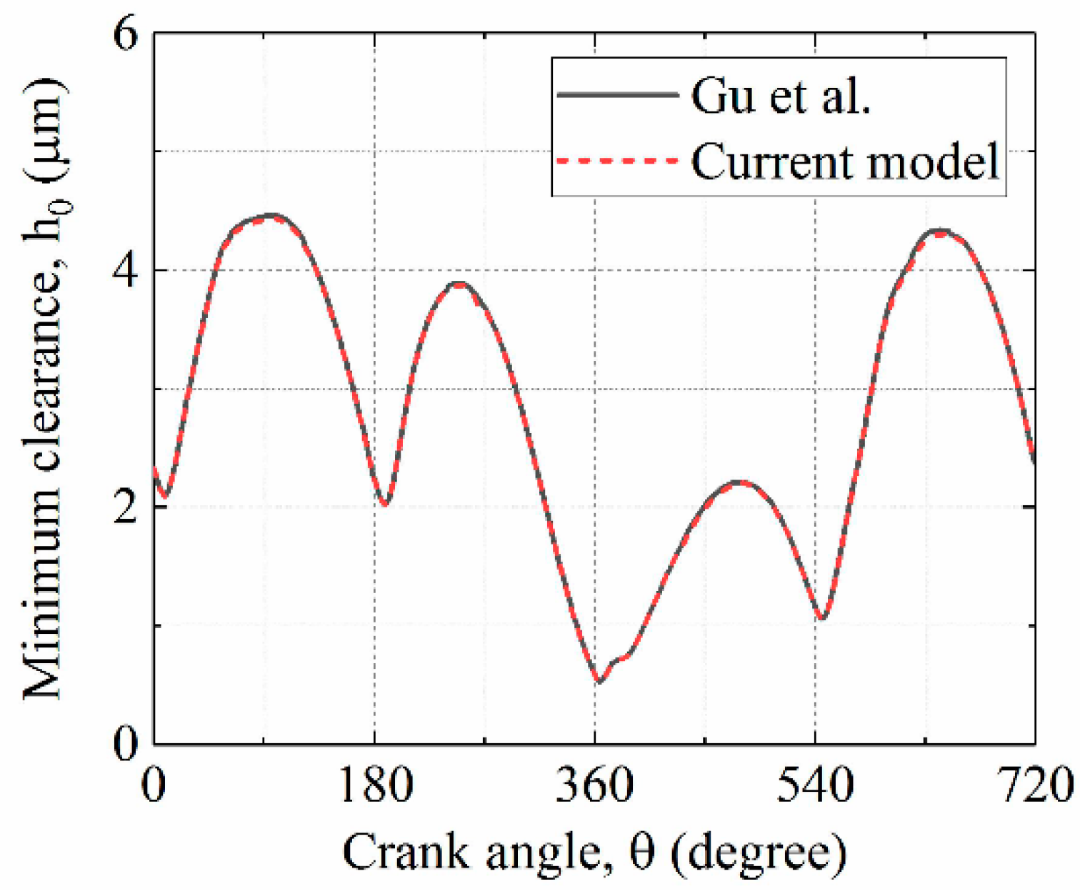
4.1. Validation of Model

To illustrate the reasonability of the presented numerical model, the minimum clearance in the RLC was calculated by the present model, and this was compared with the published result from Gu et al. [41], as shown in Figure 6. The parameters adopted in the calculation were consistent with the reference of [41]. In Figure 6, the minimum clearance calculated by the current model matches well with the result of Gu et al. [41], and the maximum difference in the minimum clearance was about 1.0%. This indicates that the presented model can be adopted to reasonably simulate the frictional behaviors of the RLC. Therefore, the frictional characteristics of the textured RLC were analyzed by using the presented model in the following sections. In the simulation, the pressure in cylinder and the sliding velocity of ring are given in Figure 7.

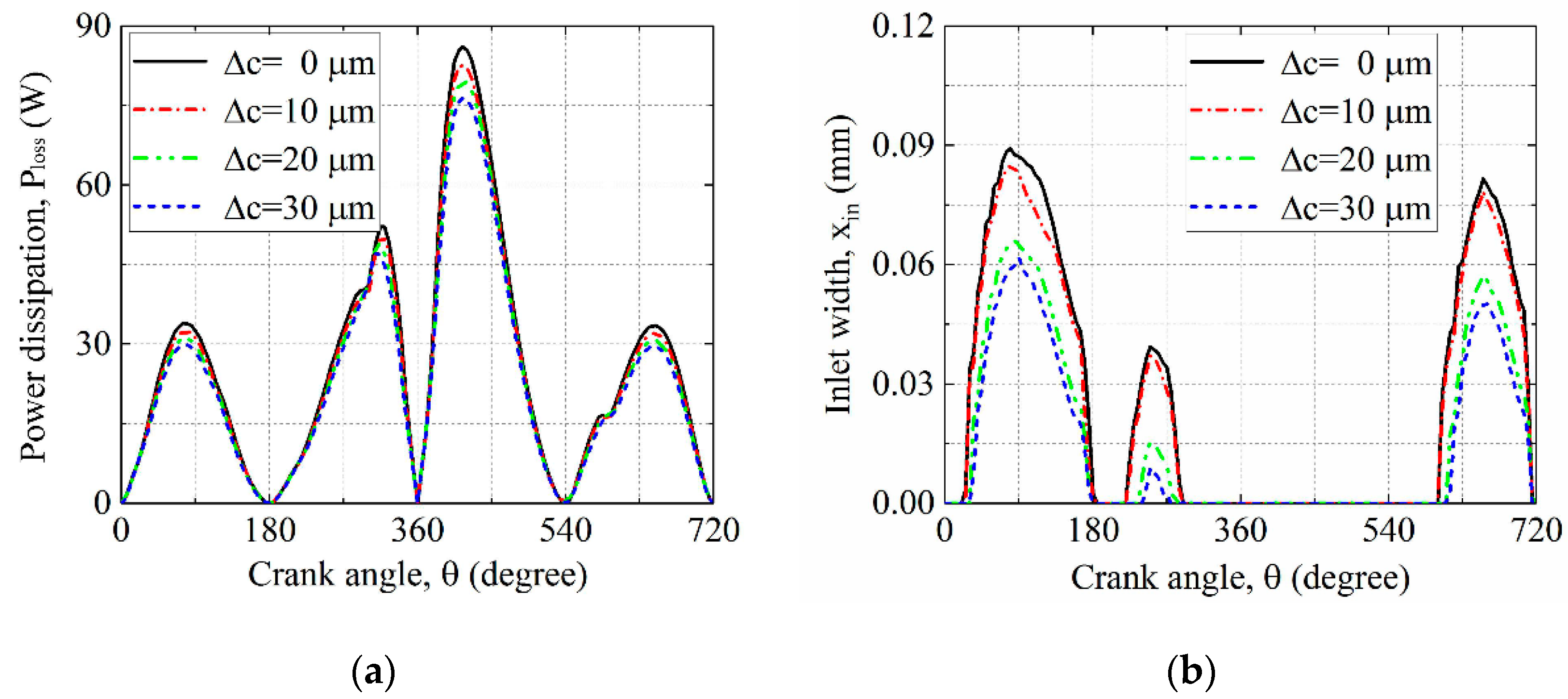
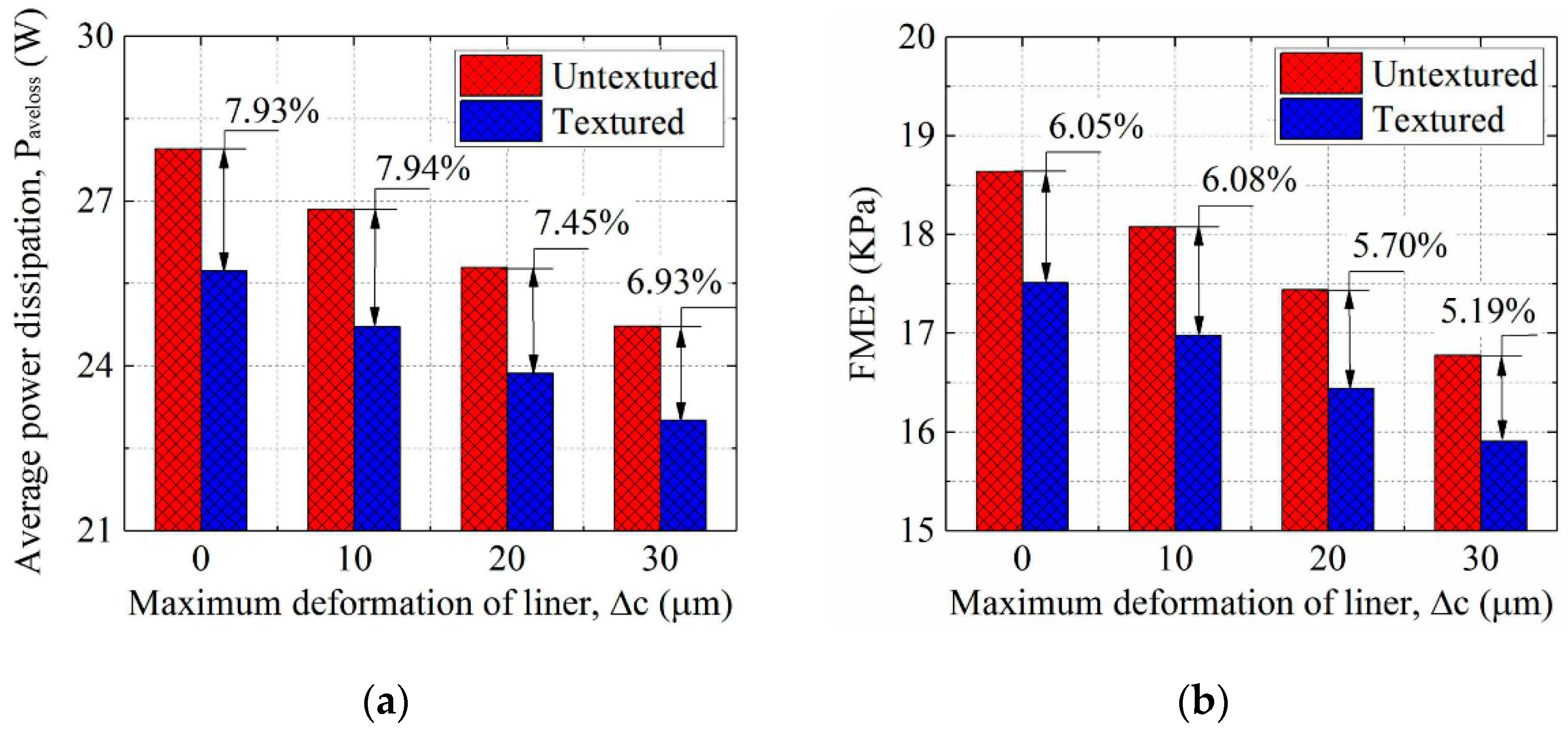
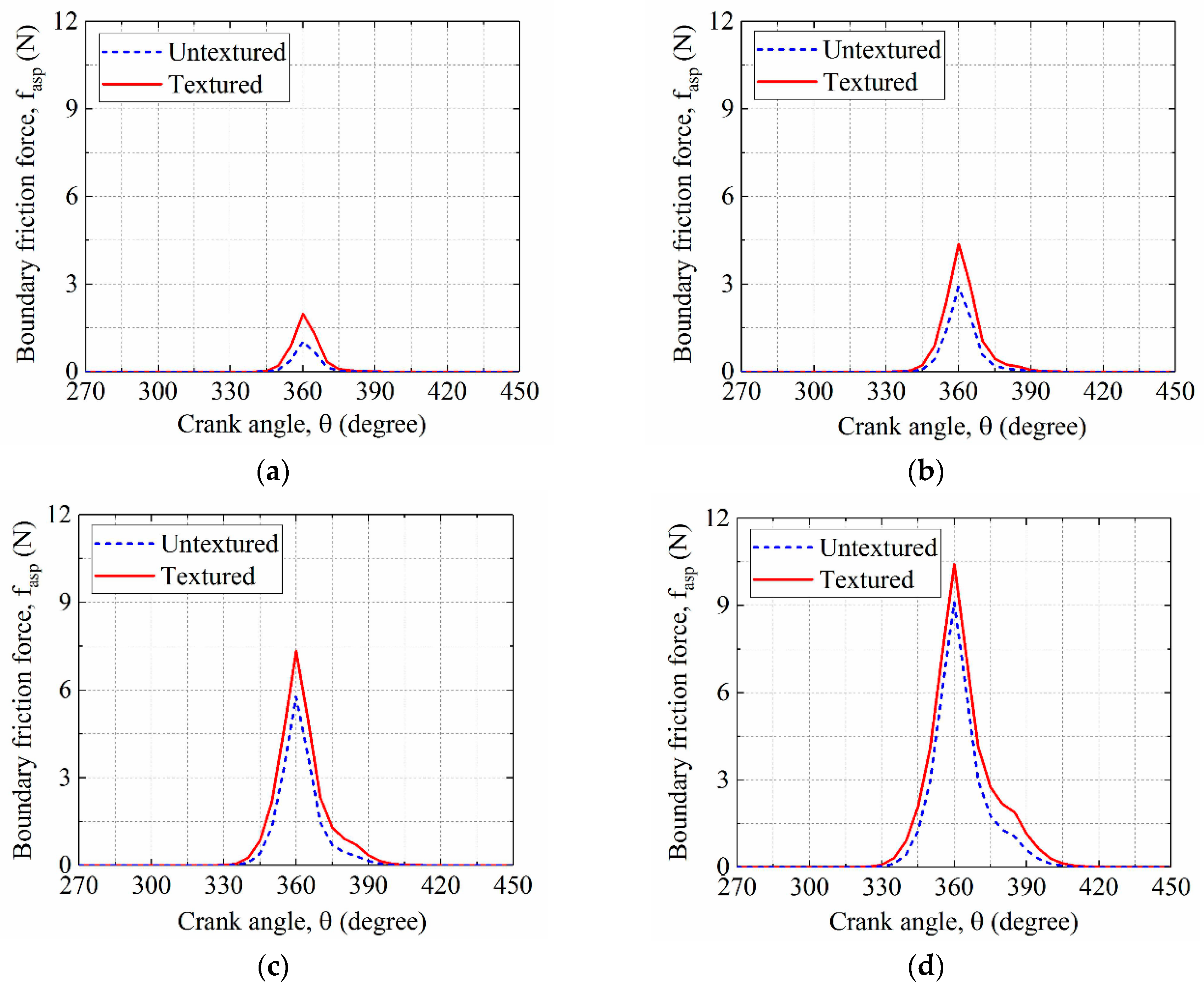
4.2. Effect of Liner Deformation

To study the effects of liner deformation on the frictional characteristics of the groove textured RLC, the friction force, power dissipation, and friction dissipation were calculated for different maximum liner deformations. Moreover, the inlet width of lubrication zone was also calculated to evaluate the inlet condition of the lubrication because it significantly affected the frictional characteristics of the RLC [18,19].
Figure 8 shows the hydrodynamic friction force and boundary friction force in the groove textured RLC for different maximum liner deformations. Compared with the groove textured RLC with ideal circular liner (i.e., the value of Δc is 0 μm), small hydrodynamic friction force and large boundary friction force were observed for the groove textured RLC with the deformed liner. Furthermore, the hydrodynamic friction force decreased and the boundary friction force increased with the increase of the maximum liner deformation. It is also observed from Figure 8 that the decrease of hydrodynamic friction force is obvious when the crank angles were 90, 270, 450, and 630º (i.e., at the middle of the strokes). The results in Figure 8 indicate that the hydrodynamic friction force and boundary fiction force in the groove textured RLC were greatly affected by the liner deformation.
Figure 9 shows the power dissipation and inlet width of lubrication zone. The result shows that the maximum liner deformation had a great influence on the power dissipation, especially at the middle of the strokes. Moreover, it can be also seen that the leading edge of ring was fully flooded (i.e., the inlet width xin was 0 mm) when the ring was near the dead centers or on the power stroke (i.e., the crank angle 360º ≤ θ ≤ 540º). However, when the ring operated near the middle of intake stroke (i.e., the crank angle θ = 90º), compression stroke (i.e., the crank angle θ = 270º), and exhaust stroke (i.e., the crank angle θ = 630º), the lubrication condition at the leading edge of the ring was starved, and the degree of starved lubrication was a decreasing function of the maximum liner deformation. This is because that the inlet width of the lubrication zone is a decreasing function of the maximum liner deformation.
The friction-reducing effect of the grooves on the ring was also evaluated for different maximum liner deformations. Figure 10 gives the hydrodynamic friction forces in the groove textured RLC and untextured RLC. The hydrodynamic friction force decreased significantly when the grooves were textured on the ring. Furthermore, a large reduction of hydrodynamic friction force was obtained at the middle of the strokes, and the reduction percentages are shown in Table 3. From Table 3, it is observed that the difference in the reduction percentage of the hydrodynamic friction force among different maximum liner deformations was small. Relatively, a large reduction percentage in the hydrodynamic friction force was observed when the maximum liner deformation was 10 μm or the ring operated on the power stroke. This means that the reduction of hydrodynamic friction force after texturing was less affected by the liner deformation. Figure 11 shows the boundary friction forces in the groove textured RLC and untextured RLC for different maximum liner deformations when the crank angle θ was 360º. Different from the results in Figure 10, the grooves on the ring were observed to increase the boundary friction force, and the increase percentages of peak boundary friction force were about 63.57%, 62.17%, 47.06%, and 45.83% when the maximum liner deformations were 0, 10, 20, and 30 μm.
Figure 12 shows the reductions of the average power dissipation and the FMEP value after texturing the grooves on the ring for various maximum liner deformations. It was observed that the ring grooves reduced the average power dissipation and FMEP value effectively. In detail, when the maximum liner deformations were 0, 10, 20, and 30 μm, the decreased percentages of the average power dissipation were about 7.93%, 7.94%, 7.45%, and 6.93%; the decreased percentages of the FMEP value were about 6.05%, 6.08%, 5.70%, and 5.19%. Furthermore, the decreased percentages of the average power dissipation and FMEP value were the decreasing functions of the maximum liner deformation when the liner deformation was considered (i.e., the value of Δc > 0 μm).
Figure 13 shows the average power dissipation caused by the hydrodynamic friction and the boundary friction for different maximum liner deformations. It was observed that the average power dissipation caused by the hydrodynamic friction was larger than that caused by the boundary friction. Furthermore, after texturing grooves on the ring, the average power dissipation caused by the hydrodynamic friction was reduced, and the average power dissipation caused by the boundary friction was increased. In details, when the maximum liner deformations were 0, 10, 20, and 30 μm, the decreased percentages of the average power dissipation caused by the hydrodynamic friction were about 8.07%, 8.10%, 7.70%, and 7.20%, and the increase percentages of the average power dissipation caused by the boundary friction were about 111.5%, 109.9%, 98.81%, and 99.82%.

4.3. Effect of Liner Temperature

The hydrodynamic and boundary friction forces in the groove textured RLC for different liner temperatures are shown in Figure 14. It was observed that the difference of hydrodynamic friction force among different liner temperatures was large, especially when the crank angles θ were 90, 270, 450, and 630°. Furthermore, when the crank angles θ were 360 and 540°, the boundary friction force appeared, and the boundary friction force was an increasing function of the liner temperature. The results demonstrate that the liner temperature has significant effect on friction.
To evaluate the friction-reducing effect of the grooves at different liner temperatures, the friction forces in the textured RLC and untextured RLC were calculated. Figure 15 shows the hydrodynamic friction forces when the liner temperatures were 60, 80, 100, and 120 °C. It can be seen that the grooves on the ring reduced the hydrodynamic friction force, and a large reduction was observed when the crank angles θ were 90, 270, 450, and 630°. Compared with the liner temperature of 60 °C, the differences of hydrodynamic friction force between the textured RLC and untextured RLC were relatively small when the liner temperature was greater than or equal to 80 °C. Furthermore, when the liner temperature was 120 °C, the reduction of hydrodynamic friction force after texturing grooves on the ring was mainly observed on the power stroke and the exhaust stroke. Figure 16 shows the boundary friction forces for various liner temperatures. The grooves on the ring were observed to increase the boundary friction force, and the increase percentages of peak boundary friction force were about 92.23%, 50.43%, 26.84%, and 14.30% when the liner temperatures were 60, 80, 100, and 120 °C.
Figure 17a shows the power dissipation of the groove textured RLC at different liner temperatures. A large difference in the power dissipation among various liner temperatures was observed, and the power dissipation decreased with the increase of the liner temperature. This is because that the hydrodynamic friction force increased with the decrease of liner temperature. This result indicates that the liner temperature significantly affected the power dissipation of the textured RLC. To evaluate the reduction of power dissipation after texturing grooves on the ring, the average power dissipation of the textured RLC and untextured RLC were compared, and the compared results are shown in Figure 17b. It can be observed that the average power dissipation of the textured RLC was lower than that of the untextured RLC. When the liner temperatures were 60, 80, 100, and 120 °C, the reductions of average power dissipation were 8.58%, 7.85%, 6.43%, and 3.93%. These results demonstrate that the grooves on the ring can greatly reduce the power dissipation of the RLC, and the reduction of average power dissipation was large when the liner temperature was low.
Figure 18 shows the average power dissipation caused by the hydrodynamic friction and boundary friction for different liner temperatures. It was observed that the grooves on the ring decreased the average power dissipation caused by the hydrodynamic friction, and the decrease percentage was a decreasing function of the liner temperature. However, the grooves on the ring also increased the average power dissipation caused by the boundary friction, and the increase percentage was also a decreasing function of the liner temperature.
Table 4 gives the FMEP values of the textured RLC and untextured RLC for various liner temperatures. In Table 4, the FMEP value decreases with the increase of the liner temperature. Moreover, the FMEP value was greatly reduced after texturing the grooves on the ring, and the reduced percentage of the FMEP value was a decreasing function of the liner temperature. This indicates that the grooves on the ring can significantly reduce the friction dissipation of the RLC, especially at low liner temperature.

5. Conclusions

A mathematical model was proposed to investigate the frictional characteristics of the groove textured RLC with a consideration of the liner deformation and the coexistence of different conditions of lubrication (i.e., fully flooded and starved). Based on the model, the effects of liner deformation and temperature on the frictional characteristics of the textured RLC were investigated. Furthermore, the friction-reducing effect of the ring grooves was also evaluated for different liner temperatures and deformations. According to the numerical results obtained in this study, the main conclusions can be made as follows:
  • Liner deformation and temperature affect the frictional characteristics of the groove textured RLC significantly. Compared with the groove textured RLC with ideal circular liner, the groove textured RLC with deformed liner had low friction dissipation and power dissipation. Furthermore, the friction dissipation and power dissipation of the groove textured RLC decreased with the increase of the liner temperature.
  • The grooves on the ring can effectively reduce the hydrodynamic friction force, power dissipation, and friction dissipation, and the reductions of average power dissipation and friction dissipation had a close relation to the liner deformation and temperature. In detail, for the groove textured RLC, the reduction percentages of the average power dissipation and friction dissipation increased with the decreases of the maximum liner deformation and liner temperature. However, when the groove textured RLC was under the mixed regime of lubrication, the grooves on the ring increased the boundary friction force.
It should be noted that these conclusions were made based on the numerical results in this study. The RLC with grooves under practical working conditions will show other complex characteristics (e.g., the dynamic liner deformation caused by piston slap). The experimental validation and investigation on the frictional performance of the RLC with grooves need to be conducted further. Moreover, the geometry optimization on the grooves was not considered in this study, and the asperity heights on the RLC surfaces were assumed to be Gaussian distributed. The optimization on the groove geometry and the frictional performance analysis on the groove textured RLC with non-Gaussian surfaces can also be considered for future directions of this research.

Author Contributions

Conceptualization, C.L.; methodology, C.L. and Y.L.; software, Y.Z.; validation, L.T. and C.G.; formal analysis, C.L.; investigation, Y.L.; resources, Y.L. and N.M.; data curation, Y.Z. and L.T.; writing—original draft preparation, C.L.; writing—review and editing, C.L. and Y.L.; visualization, C.L.; supervision, Y.Z. and N.M.; project administration, Y.L. and C.L.; funding acquisition, Y.L. and C.L.

Funding

This research was funded by the National Natural Science Foundation of China (Grant No. 51775428), the Open Project of State Key Laboratory of Digital Manufacturing Equipment and Technology (Grant No. DMETKF2017014), the Project of PhD Innovation Foundation of Xi’an University of Technology (Grant No. 310-252071701).

Conflicts of Interest

The authors declare no conflict of interest.

References

  1. Checo, H.M.; Ausas, R.F.; Jai, M.; Cadalen, J.P.; Choukroun, F.; Buscaglia, G.C. Moving textures: Simulation of a ring sliding on a textured liner. Tribol. Int. 2014, 72, 131–142. [Google Scholar] [CrossRef]
  2. Mezghani, S.; Demirci, I.; Zahouani, H.; Mansori, M.E. The effect of groove texture patterns on piston-ring pack friction. Precis. Eng. 2012, 36, 210–217. [Google Scholar] [CrossRef] [Green Version]
  3. Gu, C.X.; Meng, X.H.; Xie, Y.B.; Yang, Y.M. Effect of surface texturing on ring/liner friction under starved lubrication. Tribol. Int. 2016, 94, 591–605. [Google Scholar] [CrossRef]
  4. Mishara, P.; Ramkumar, P. Effect of additives on a surface textured piston ring-cylinder liner system. Tribol. Mater. Surf. Interfaces 2019, 13, 67–75. [Google Scholar] [CrossRef]
  5. Usman, A.; Park, C.W. Modeling and simulation of frictional energy loss in mixed lubrication of a textured piston compression ring during warm-up of spark ignition engine. Int. J. Engine Res. 2017, 18, 293–307. [Google Scholar] [CrossRef]
  6. Francisco, J.P.; Vl descu, S.C.; Reddyhoff, T.; Dini, D. Transient experimental and modelling studies of laser-textured micro-grooved surfaces with a focus on piston-ring cylinder liner contacts. Tribol. Int. 2017, 113, 125–136. [Google Scholar]
  7. Meng, F.M.; Zhang, Y.Y.; Hu, Y.Z.; Wang, H. Numerical study of influences of hard particles in lubricant on tribological performances of the piston ring. Proc. Inst. Mech. Eng. Part C J. Mech. Eng. Sci. 2007, 221, 361–372. [Google Scholar] [CrossRef]
  8. Ronen, A.; Etsion, I.; Kligerman, Y. Friction-reducing surface-texturing in reciprocating automotive components. Tribol Trans. 2001, 44, 359–366. [Google Scholar] [CrossRef]
  9. Kligerman, Y.; Etsion, I.; Shinkarenko, A. Improving tribological performance of piston rings by partial surface texturing. ASME J. Tribol. 2005, 127, 632–638. [Google Scholar] [CrossRef]
  10. Caciu, C.; Decencière, E.; Jeulin, D. Parametric optimization of periodic textured surfaces for friction reduction in combustion engines. Tribol. Trans. 2008, 51, 533–541. [Google Scholar] [CrossRef]
  11. Noutary, M.P.; Biboulet, N.; Lubrecht, A.A. A robust piston ring lubrication solver: Influence of liner groove shape, depth and density. Tribol. Int. 2016, 100, 35–40. [Google Scholar] [CrossRef]
  12. Ezhilmaran, V.; Vasa, N.J.; Vijayarahavan, L. Investigation on generation of laser assisted dimples on piston ring surface and influence of dimple parameters on friction. Surf. Coat. Tech. 2018, 335, 314–326. [Google Scholar] [CrossRef]
  13. Usman, A.; Park, C.W. Optimizing the tribological performance of textured piston ring-liner contact for reduced frictional losses in SI engine: Warm operating conditions. Tribol. Int. 2016, 99, 224–236. [Google Scholar] [CrossRef]
  14. Morris, N.; Rahmani, R.; Rahnejat, H.; King, P.D.; Howell-Smith, S. A numerical model to study the role of surface textures at top dead center reversal in the piston ring to cylinder liner contact. ASME J. Tribol. 2016, 138, 021703. [Google Scholar] [CrossRef]
  15. Yin, B.F.; Sun, S.; Wang, B.W.; Qian, Y.Q. Numerical research on tribological performance of textured liner surface under different combustion modes. ASME J. Eng. Gas Turb. Power. 2017, 139, 011504. [Google Scholar] [CrossRef]
  16. Liu, C.; Lu, Y.J.; Zhang, Y.F.; Li, S.; Müller, N. Numerical study on the lubrication performance of compression ring-cylinder liner system with spherical dimples. PLoS ONE 2017, 12, e0181574. [Google Scholar] [CrossRef] [PubMed]
  17. Söderfjäll, M.; Larsson, R.; Marklund, P.; Almqvist, A. Texture-induced effects causing reduction of friction in mixed lubrication for twin land oil control rings. Proc. Inst. Mech. Eng. Part J J. Eng. Tribol. 2018, 232, 166–178. [Google Scholar] [CrossRef]
  18. Meng, X.H.; Gu, C.X.; Xie, Y.B.; Li, W.X. A two-dimensional starved lubrication analysis method for textured surfaces. Int. J. Engine Res. 2016, 17, 1062–1076. [Google Scholar] [CrossRef]
  19. Gu, C.X.; Meng, X.H.; Xie, Y.B.; Kong, X.L. Performance of surface texturing during start-up under starved and mixed lubrication. ASME J. Tribol. 2017, 139, 011702. [Google Scholar] [CrossRef]
  20. Gu, C.X.; Meng, X.H.; Zhang, D. Analysis of the coated and textured ring/liner conjunction based on a thermal mixed lubrication model. Friction 2018, 6, 420–431. [Google Scholar] [CrossRef]
  21. Usman, A.; Cheema, T.A.; Park, C.W. Tribological performance evaluation and sensitivity analysis of piston ring lubricating film with deformed cylinder liner. Proc. Inst. Mech. Eng. Part J J. Eng. Tribol. 2015, 229, 1455–1468. [Google Scholar] [CrossRef]
  22. Rahmani, R.; Theodossiades, S.; Rahnejat, H.; Fitzsimons, B. Transient elastohydrodynamic lubrication of rough new or worn piston compression ring conjunction with an out-of-round cylinder bore. Proc. Inst. Mech. Eng. Part J J. Eng. Tribol. 2012, 226, 284–305. [Google Scholar] [CrossRef] [Green Version]
  23. Overgaard, H.; Klit, P.; Vølund, A. Investigation of different piston ring curvatures on lubricant transport along cylinder liner in large two-stroke marine diesel engines. Proc. Inst. Mech. Eng. Part J J. Eng. Tribol. 2018, 232, 85–93. [Google Scholar] [CrossRef]
  24. Li, G.X.; Gu, F.S.; Wang, T.; Lu, X.C.; Zhang, L.; Zhang, C.F.; Ball, A. An improved lubrication model between piston rings and cylinder liners with consideration of liner dynamic deformations. Energies 2017, 10, 2122. [Google Scholar] [CrossRef]
  25. Liu, C.; Lu, Y.J.; Zhang, Y.F.; Li, S.; Kang, J.X.; Müller, N. Numerical study on the tribological performance of ring/liner system with consideration of oil transport. ASME J. Tribol. 2019, 141, 011701. [Google Scholar] [CrossRef]
  26. Rahmani, R.; Rahnejat, H.; Fitzsimons, B.; Dowson, D. The effect of cylinder liner operating temperature on frictional loss and engine emissions in piston ring conjunction. Appl. Energy 2017, 191, 568–581. [Google Scholar] [CrossRef] [Green Version]
  27. Dunaevsky, V.V. Analysis of distortions of cylinders and conformability of piston rings. Tribol. Trans. 1990, 33, 33–40. [Google Scholar] [CrossRef]
  28. Ma, M.T.; Smith, E.H.; Sherrington, I. Analysis of lubrication and friction for a complete piston-ring pack with an improved oil availability model part 2: Circumferentially variable film. Proc. Inst. Mech. Eng. Part J J. Eng. Tribol. 1997, 211, 17–27. [Google Scholar] [CrossRef]
  29. Usman, A.; Park, C.W. Numerical investigation of tribological performance in mixed lubrication of textured piston ring-liner conjunction with a non-circular cylinder bore. Tribol. Int. 2017, 105, 148–157. [Google Scholar] [CrossRef]
  30. Usman, A.; Park, C.W. Mixed lubrication of piston compression ring with deformed cylinder liner during warm-up of spark ignition engine. Proc. Inst. Mech. Eng. Part J J. Eng. Tribol. 2016, 230, 1288–1309. [Google Scholar] [CrossRef]
  31. Zhu, X.P.; Bai, S.; Chen, Y.; Song, H.N. Deformation analysis of the cylinder liner based on mechanical-thermal coupling. Des. Manuf. Diesel Engine 2013, 3, 9–14. [Google Scholar]
  32. Gu, C.X.; Meng, X.H.; Xie, Y.B.; Zhang, D. Mixed lubrication problems in the presence of textures: An efficient solution to the cavitation problem with consideration of roughness effects. Tribol. Int. 2016, 103, 516–528. [Google Scholar] [CrossRef]
  33. Patir, N.; Cheng, H.S. An average flow model for determining effects of three-dimensional roughness on partial hydrodynamic lubrication. ASME J. Lubr. Technol. 1978, 100, 12–17. [Google Scholar] [CrossRef]
  34. Patir, N.; Cheng, H.S. Application of average flow model to lubrication between rough sliding surfaces. ASME J. Lubr. Technol. 1979, 101, 220–229. [Google Scholar] [CrossRef]
  35. Wu, C.; Zheng, L. An average Reynolds equation for partial film lubrication with a contact factor. ASME J Tribol. 1989, 111, 220–229. [Google Scholar] [CrossRef]
  36. Morris, N.; Rahmani, R.; Rahnejat, H.; King, P.D.; Fitzsimons, B. Tribology of piston compression ring conjunction under transient thermal mixed regime of lubrication. Tribol. Int. 2013, 59, 248–258. [Google Scholar] [CrossRef] [Green Version]
  37. Gulwadi, S.D. A mixed lubrication and oil transport model for piston rings using a mass-conserving algorithm. ASME J. Eng. Gas Turb. Power. 1998, 120, 199–208. [Google Scholar] [CrossRef]
  38. Morris, N.; Mohammadpour, M.; Rahmani, R.; Johns-Rahnejat, P.M.; Rahnejat, H.; Dowson, D. Effect of cylinder deactivation on tribological performance of piston compression ring and connecting rod bearing. Tribol. Int. 2018, 120, 243–254. [Google Scholar] [CrossRef]
  39. Pu, W.; Zhu, D.; Wang, J.X. A starved mixed elastohydrodynamic lubrication model for the prediction of lubrication performance, friction and flash temperature with arbitrary entrainment angle. ASME J. Tribol. 2018, 140, 031501. [Google Scholar] [CrossRef]
  40. Wang, F.; Zhao, S.X. The research on the properties of the journal bearing based on the P-θ model. Mach. Des. Manuf. 2016, 11, 76–79. [Google Scholar]
  41. Gu, C.X.; Meng, X.H.; Xie, Y.B.; Li, P. A study on the tribological behavior of surface texturing on the nonflat piston ring under mixed lubrication. Proc. Inst. Mech. Eng. Part J J. Eng. Tribol. 2016, 230, 452–471. [Google Scholar] [CrossRef]
Figure 1. Schematic diagrams of the groove textured ring and ring-liner conjunction (RLC): (a) Groove textured ring; (b) groove textured RLC.
Energies 12 02761 g001
Figure 2. Schematic diagram of the deformed liner for any cross section in the axial direction.
Energies 12 02761 g002
Figure 3. Schematic diagram of lubrication condition: (a) Fully flooded lubrication condition; (b) Starved lubrication condition.
Energies 12 02761 g003
Figure 4. Schematic diagram of the oil transport model.
Energies 12 02761 g004
Figure 5. Calculation flow chart for the numerical model.
Energies 12 02761 g005
Figure 6. Minimum clearances calculated by the current model and the model of Gu et al. [41].
Energies 12 02761 g006
Figure 7. Pressure in cylinder and ring velocity adopted in the simulation.
Energies 12 02761 g007
Figure 8. Friction forces in the groove textured RLC for different maximum deformations of liner: (a) Hydrodynamic friction force; (b) boundary friction force.
Energies 12 02761 g008
Figure 9. Power dissipation and inlet widths of lubrication zone of the groove textured RLC for different maximum liner deformations: (a) Power dissipation; (b) inlet width.
Energies 12 02761 g009
Figure 10. Hydrodynamic friction forces in the textured RLC and untextured RLC: (a) Δc is 0 μm; (b) Δc is 10 μm; (c) Δc is 20 μm; and (d) Δc is 30 μm.
Energies 12 02761 g010
Figure 11. Boundary friction forces in the textured RLC and untextured RLC: (a) Δc is 0 μm; (b) Δc is 10 μm; (c) Δc is 20 μm; and (d) Δc is 30 μm.
Energies 12 02761 g011aEnergies 12 02761 g011b
Figure 12. Reduced percentages of the average power dissipation and friction mean effective pressure (FMEP) value after texturing grooves on the ring for different maximum liner deformations: (a) Average power dissipation; (b) FMEP value.
Energies 12 02761 g012
Figure 13. Average power dissipation caused by the hydrodynamic friction and boundary friction for different maximum deformations of liner: (a) Average power dissipation caused by the hydrodynamic friction; (b) average power dissipation caused by boundary friction.
Energies 12 02761 g013
Figure 14. Friction forces in the groove textured RLC for different liner temperatures: (a) Hydrodynamic friction force; (b) boundary friction force.
Energies 12 02761 g014
Figure 15. Hydrodynamic friction forces of the textured RLC and untextured RLC: (a) Tliner is 60 °C; (b) Tliner is 80 °C; (c) Tliner is 100 °C; and (d) Tliner is 120 °C.
Energies 12 02761 g015
Figure 16. Boundary friction forces of the textured RLC and untextured RLC: (a) Tliner is 60 °C; (b) Tliner is 80 °C; (c) Tliner is 100 °C; (d) Tliner is 120 °C.
Energies 12 02761 g016
Figure 17. Power dissipation and average power dissipation of the textured RLC for different liner temperatures: (a) Power dissipation; (b) average power dissipation.
Energies 12 02761 g017
Figure 18. Average power dissipation caused by the hydrodynamic friction and boundary friction for different liner temperatures: (a) Average power dissipation caused by the hydrodynamic friction; (b) average power dissipation caused by the boundary friction.
Energies 12 02761 g018
Table 1. Geometry parameters of the RLC.
ParameterValueUnit
Stroke length, ls90mm
Axial width of ring, b1mm
Thickness of ring, ar3.5mm
Nominal radius of liner, r42mm
Young’s modulus of ring, E1250GPa
Young’s modulus of liner, E2120GPa
Poisson’s ratio of ring, τ10.3-
Poisson’s ratio of liner, τ20.3-
Surface roughness of ring, σ10.42μm
Surface roughness of liner, σ20.48μm
Table 2. Parameters of lubricant.
ParametersValueUnit
correlation factor, α00.06782mPa·s
correlation factor, α1880.29°C
correlation factor, α2103.08°C
Reference density of lubricant at 40 °C, ρ 0 771.02kg·m−3
Reference viscosity of lubricant at 40 °C, μ031.87mPa·s
Table 3. Reduction percentages of the hydrodynamic friction force at the middle of strokes for different maximum liner deformations.
Maximum Deformation of Liner, ΔcReduction Percentage
Intake StrokeCompression StrokePower StrokeExhaust Stroke
0 μm9.41%8.72%10.99%8.54%
10 μm9.45%8.82%11.06%8.80%
20 μm9.18%8.47%10.20%8.67%
30 μm9.11%8.27%9.15%8.64%
Table 4. FMEP values in the textured RLC and untextured RLC for different liner temperatures.
Liner Temperature, TlinerFMEP ValueReduce Percentage
Textured RingUntextured Ring
60 °C21.2523.459.38%
80 °C16.7718.368.66%
100 °C13.4214.527.58%
120 °C11.0911.715.29%

