Thyristor Arc Eliminator for Protection of Low Voltage Electrical Equipment


Institute of Electric Power Engineering, Poznan University of Technology, Piotrowo 3A, 60-965 Poznan, Poland
*
Author to whom correspondence should be addressed.
Energies 2019, 12(14), 2749; https://doi.org/10.3390/en12142749
Submission received: 5 June 2019
/
Revised: 9 July 2019
/
Accepted: 17 July 2019
/
Published: 18 July 2019
Abstract
:The paper presents the layout of two opposing thyristors working as an Arc Eliminator (AE). The presented solution makes it possible to protect an electrical apparatus against the effects of an arcing fault. An Arc Eliminator is assumed to be a device cooperating with the protected apparatus. Thyristors were used because of their speed of operation and a relatively lower cost compared to other semiconductors with the same current-carrying capacity. The proposed solution, as one of the few currently available, makes it possible to eliminate the fault arc—both at short-circuit currents and current values to which overcurrent protections do not react. A test circuit was designed and made to study the effectiveness of the thyristor arc eliminator. A series of tests was carried out with variable impedance in the arc branch, including the influence of circuit inductance on arc time. It was found that the thyristor arc eliminator effectively protects devices powered from a low voltage power network against the effects of a fault or arc fault. The correctness of system operation for a wide range of impedance changes in the circuit feeding the arc location was demonstrated.
1. Introduction
1.1. Motivation
Most arcing faults in a power system can be described as large discharges of electrical energy between conductors. The occurrence of short circuits can be indirectly conditioned by many factors, such as mechanical damage [1], insulation aging [2], overvoltages [3] and surface discharges [4]. In addition, arching faults in a power system that are associated with erroneous switching activities, accidental rapprochement or touching of active parts, as well as fatigue, insufficient concentration, and haste at work may contribute to short circuits directly [5]. The occurrence of the electric arc phenomenon is accompanied by the release of significant energy, the effects of which may be the heating and destruction of the power equipment, as well as a sharp growth of pressure inside the enclosed elements. In addition to hazards to the devices (both in the switchgear and near the location of short circuit), this energy can also be a threat to people in close proximity to the arcing (glare, burn) [6,7,8].
Improving the operational safety of receiving and power circuits requires (sometimes on a compulsory basis) a reduction of the effects of fault currents and occurrence of a fault arc. From the existing methods of elimination of the effects of arcing fault, two main ones [9] can be distinguished – limitation of the electric current value and limitation of arc discharge duration. The limitation of the current value is achieved by connecting series impedance to the powered circuit. However, it can have a negative effect on the activation time of overcurrent protection, thus leading to a longer arc discharge time and increased energy released in the electric arc. Consequently, the time-limitation approach is usually preferred [6]. Switches equipped with power electronics actuators (semiconductor switches) meet the condition of shortening the arc time and can be used to effectively protect circuits against the effects of an arc fault, short-circuit arcing, and arc burning at operating and overload currents [9]. The use of a semiconductor arc eliminator enables obtaining virtually instantaneous elimination of the arc fault in the damaged circuit, commutation of short-circuit current without an arc in the branch of the arc eliminator, shortening the time of influence of thermal effects in the protected circuit, and even (when faults are detected before the first amplitude of short-circuit current) reducing the effects of electrodynamic interactions [10].
Extinguishing the arc fault with the use of an arc eliminator is based on the fact that as soon as a flash (coming from the arc) appears in the affected circuit, it is detected and one of the parallel semiconductor devices is triggered [11]. The voltage of the burning arc is usually greater than 20 V. Such a voltage value is sufficient for the semiconductor to switch to the conduction state, which results in a very fast bypassing of the electric circuit affected by the failure, aimed at creating an alternative (privileged) path for the current flow. In this way, current is immediately eliminated in the protected circuit. The voltage of the conductive semiconductors is much smaller than the voltage of the burning arc, which in turn makes it possible to extinguish the arc fault.
1.2. Literature Review
The Arc Eliminator (AE) belongs to the family of bypass system of the electric circuits above the place affected by the failure. Its task is to quickly eliminate the arc fault, preventing the further development of an electric discharge. Operation of the system relies on commutating the current in the branch of the AE at the moment of failure in the protected electrical circuit. The bypass system can be used in a wide range of applications such as:
- −
- motor drive systems using frequency converters (inverters), in which an arc fault may not be eliminated by the protection system [12],
- −
- industrial manufacturing facilities where capacitors play a role of reactive power compensation [13],
- −
- power systems using photovoltaic panels, where the bypass system can suppress overvoltages, which can induce excessive overheating of cells and, as a result, cause permanent damage to photovoltaic cells [14],
- −
- a hybrid circuit breaker, which is a combination of a mechanical switch and a semiconductor bypass branch, where the bypass system plays the role of un-arc circuit current commutation [15],
- −
- a hybrid vacuum switch, where the vacuum chamber is bypassed by a semiconductor circuit, which commutates the flow of the electric current without an arc [16],
- −
- an arc protection system in electric vehicles powered with constant voltage [17].
There are many solutions for the construction of drive systems and branches of bypass circuits. One of them is a mechanical switch whose drive is based on Thomson’s electromagnetic coil [18,19]. The advantage of this solution is a mechanical bypass system characterized by appropriate speed and high current-carrying capacity. However, the disadvantage of the solution is the complexity of the drive mechanism and the cost of its implementation. Another solution is spring mechanisms accelerated by electromagnetic systems [6,20,21]. In contrast to the drive built on the basis of the Thomson coil, these mechanisms are characterized by simpler construction and lower cost of execution. Yet, the disadvantage of this solution is a longer operating time. Ultra-fast earthing switches based on the vacuum chamber are also used as drive systems for bypass branches [22]. It permits commutation of the current without an arc in the circuit affected by the failure. The most unfavourable switching operation of the vacuum chamber is short circuit closure, which can cause the working contacts to bond. The pyrotechnic charge explosion systems are also used to interrupt the fault arc [23]. This solution offers a high response speed. Nevertheless, each operation of the limiter requires the replacement of detonators and explosive charges, which entails additional costs and downtimes in the supply of electricity. One of the most promising solutions for elimination of the fault arc is semiconductor bypass systems [10]. With regard to the aforementioned solutions, they are characterized by much faster activation (from the moment of arc detection to the time of full shunting of the place affected by the failure), ease of making the complete arc-protecting device, and a low cost of production. One disadvantage of this solution is the limited possibility of using the protection in medium voltage networks, which requires the serial connection of semiconductor devices in order to obtain the required voltage strength.
1.3. Contributions and Paper Organization
Research into the use of the arc eliminator semiconductor is based on the application of bypass thyristor branch [10]. However, the authors of these tests present only the results obtained through trials in a system fed from capacitor batteries. The effect of this is the course of a single half-wave of current starting in the amplitude of the supply voltage. In addition, Zhang and others in reference [10] only focused on two circuit inductance values. Therefore, in this paper, the authors present the results of research from an attempt to extinguish the electric arc using two thyristors connected in opposition supplied with alternating current of frequency of 50 Hz, for over a dozen values of the circuit inductance. This solution made it possible to confirm the effectiveness of protection of power circuits against the effects of an electric arc in devices fed from AC mains under resistive and inductive loads. The traditional overcurrent protections do not eliminate the electric arc with currents below their response currents. The proposed system accomplishes both the extinguishing of the arc and the forcing switch-off by the main overcurrent protection in the supply circuit. The system of two oppositely connected thyristors, presented and examined in this paper, was proposed due to the expected speed of action.
The paper has been organized in the following way. The second chapter explains the principle of the arc eliminator. The designed and built-in test circuit is also presented in detail. The third chapter presents the results of experimental investigations on the ability to extinguish the arc in AC low voltage networks using the thyristor arc eliminator. The results of the study were analyzed and discussed in the fourth chapter. The last, fifth chapter contains a summary and final conclusions.
2. Thyristor Arc Fault Eliminator
2.1. Principle of Operation
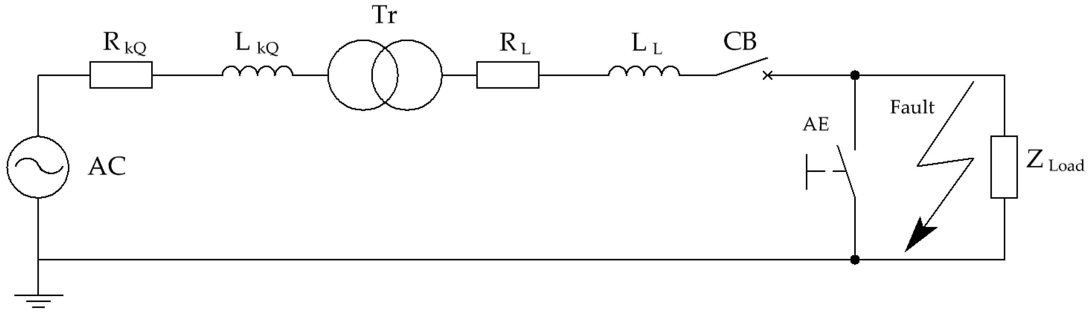
The thyristor arc eliminator (AE) is a protective device connected in parallel to the load (it can be placed in e.g., the electrical switchboard). A substitute diagram of the low voltage network circuit is shown in Figure 1.
Assuming that the supply voltage at the moment of fault has the instantaneous value described by this equation:
at the moment of the appearance of the electric arc, the instantaneous value of short-circuit current i flowing through the secondary winding of the transformer is the sum of the instantaneous values of alternating-current component iAC and direct-current component iDC of the short-circuit current:
where ω is a voltage pulsation, φZ is the short-circuit impedance argument, Ψ is the phase angle of voltage at the moment of short-circuit, I”K is the effective value of the initial short circuit current [A], and L and R are the elements of the fault circuit impedance.
An electric arc may ignite during the fault current flow. Activation of the electric arc detector generates a signal that controls the arc eliminator (AE). A virtually immediate activation of AE commutes the flow of fault current in the bypass (AE) until the main switch is activated or the electric arc is put out. Because the voltage drop on the thyristor arc eliminator (AE) is negligible compared to the arc voltage, the arc is extinguished in a very short time, often without the main circuit protection being switched off.
In the absence of an arc eliminator (AE), the total time of turning off the arc fault is influenced by fault detection time and time of tripping the circuit breaker (CB). Apart from the time needed to activate the disturbance detector (activation of the optical, voltage, current component, etc.) and send control signals, the decisive aspect is the time of delay of tripping the circuit breaker, which ranges between 20 ms and 60 ms for various protection devices in the low-voltage network. During this time, a burning electric arc, which is generating heat energy, may cause a complete destruction of the electrical apparatus, undermine the insulation of power supply cables, or damage the inside of the electrical switchgear.
Arc energy Wa is described by the following dependence:
where ua is the instantaneous value of the arc voltage [V], ia is the instantaneous value of arc current [A], and Ta is the duration of the electric arc [s].
The energy of a 20 ms arc for the rms value of 1 kA current and 80 V voltage is 1.6 kJ. Extending the arc fault duration to 60 ms results in an increase of the arc energy to 4.8 kJ. Assuming the arc voltage which does not undergo any significant changes, the arc energy increases in direct proportion to the arc time and the value of the fault current. It is assumed that for arc energy values lower than 100 kJ, repairs of electrical equipment mainly boil down to their cleaning [24]. The task of the arc eliminator is to shorten the arc time, whereby the amounts of energy emitted on the arc will be reduced.
The arc eliminator (AE) is only activated when an electric arc occurs. The solution can protect electrical equipment installed in e.g., a switchgear. The bypass branch of the arc eliminator can force the flow of a large fault current, therefore it is necessary to provide additional protection for the transformer in the switchgear station.
The thyristor shunt branch may in the least favorable case conduct through the time of a half-wave of the flowing current (10 ms). This time does not result from the difficulty to extinguish the arc with the AE but from switching off the thyristor, which stops conducting when the current passes through zero. In order not to damage the thyristors during the flow of the fault current, their limit parameters must be properly selected and the thyristor itself must be equipped with a heat sink to dissipate the heat.
2.2. Circuit Design
At the moment of detecting a flash of an electric arc, the short circuit is bypassed by a system of two reciprocally connected thyristors, which commutate the flow of current in the branch bypassing the place where the interference has occurred. The voltage drop on the conductive thyristors is lower than the voltage of the burning arc. The electric arc is extinguished. The test used TR51-80-12-76 (Unitra-Lamina, Poland) thyristors. The parameters of the thyristors are presented in Table 1.
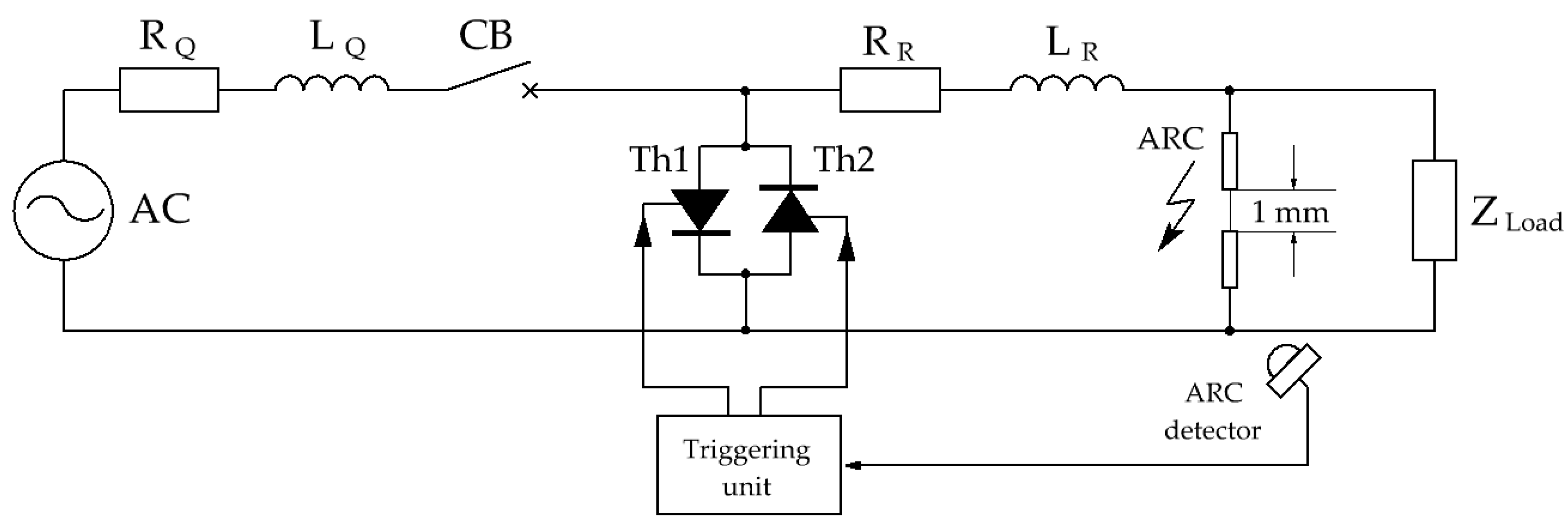
In order to test the effectiveness of two oppositely connected thyristors operating as an arc eliminator (AE) in low-voltage networks and powered by the available power system, the test electrical circuit shown in Figure 2 was built.
The triggering unit works on the basis of arc detector signals (ARC detector), activate the arc eliminator (AE), which consists of oppositely connected Th1 and Th2 thyristors. Such connection allows its use in alternating current networks with a possible random emergency state. Thyristor Th1 conducts for the positive half-wave of current, and thyristor Th2 takes over to conduct for the negative half-wave.
The arc source is a pair of cylindrical carbon electrodes with a diameter of 5.76 mm, facing each other and separated by 1 mm. A fusible element is inserted between the electrodes, which after a preselected time delay (resulting from the diameter of the fusible element) initiates the ignition of the electric arc. For safety reasons, the arc generating system (electrode with a fuse and flash detector) is enclosed in an insulating casing.
The test circuit shown in Figure 2 is powered from an AC electrical network with an effective voltage of 230 V. The measured impedance of the ZQ short circuit loop of the power supply circuit is 0.197 Ω. It is the sum of resistances (RQ = 0.196 Ω) and inductance (LQ = 0.148 mH). The expected amplitude of the short-circuit current Ik directly at the terminals of the power source is 1650 A. In series in the arc generator circuit there is variable impedance ZR (RR, LL), enabling the arc current to be regulated. The impedance ZLoad is the load of the tested system, where ZLoad >> ZQ + ZR.
3. Experiments Results
Figure 3 shows a fragment of the test circuit of the arc eliminator together with the marked points of measurement signal registration. The supply voltage is recorded in relation to the PE protective conductor. The arc voltage has been registered using a differential voltage probe DP-50 (Pintek Electronics Co. Ltd., Shulin, New Taipei City, Taiwan). The measuring probes of the differential voltage probe were placed as close as possible to the electrodes of the arc generator. The value of current in the branches of the arc eliminator (AE) and load, as well as the current drawn from the source, were registered using the model current clamps PAC22 (Chauvin Arnoux, Paris, France).
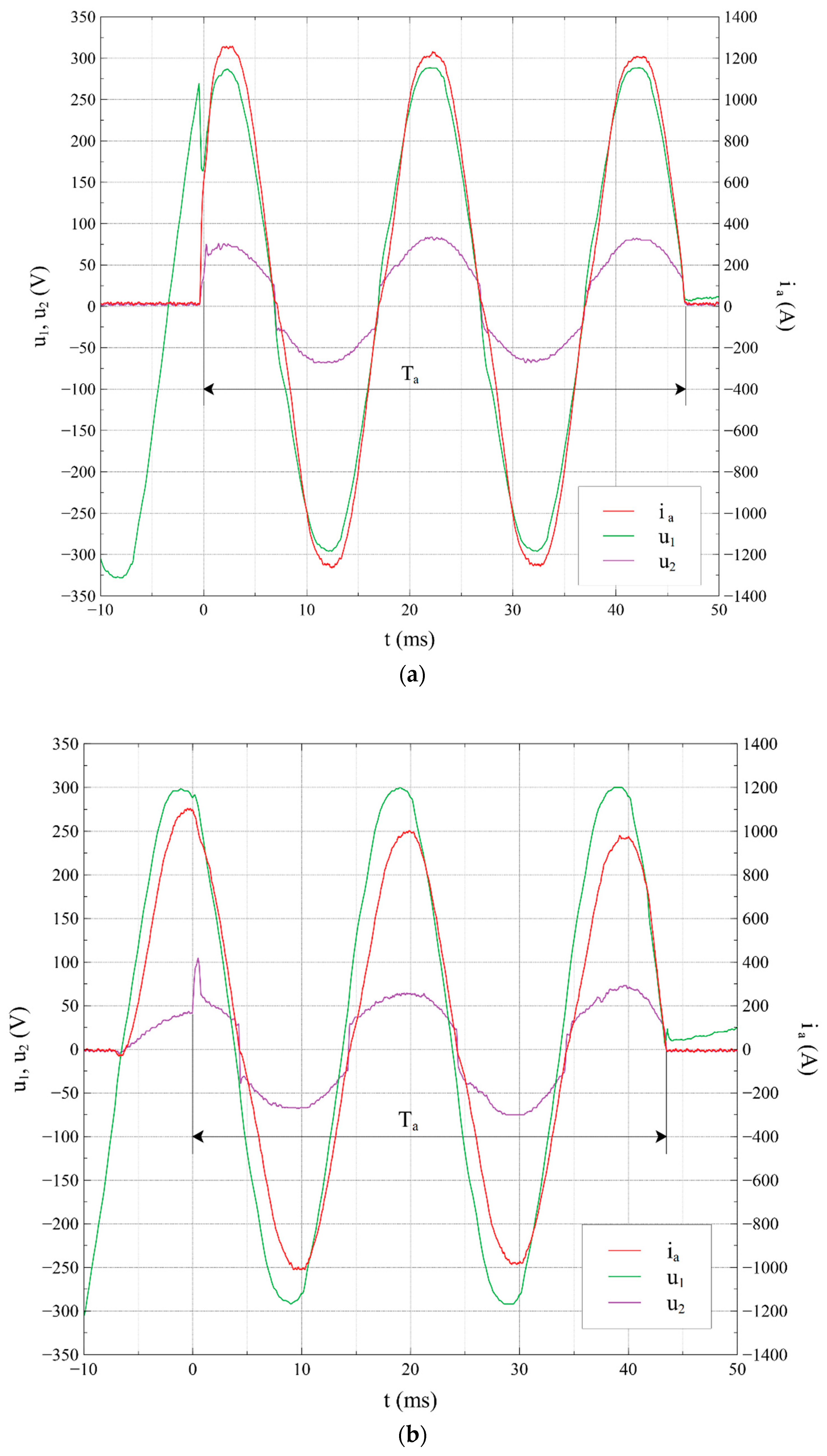
Figure 4a shows the current curve ia, supply voltage U1 and voltage measured on the electrodes of the arc generator U2, registered in the system without the arc eliminator (AE). The presented experiment corresponds to a short circuit occurring close to the arc elimination system (regulatory impedance ZR is practically negligible). The current flow is maintained for 47 ms until the main short-circuit protection is activated. The course of the short-circuit current contains the periodic component AC and a small non-periodic component DC hence the amplitude of the current Ia is decreasing. The peak current value is 1250 A. In order to facilitate readings, the moment t = 0 s, was adopted at the moment of arc ignition. During the current flow exceeding the permissible value for the fusible element, after a time of approx. 0.6 ms, arc ignition occurs between the electrodes. Then the arc burns between the carbon electrodes for approximately 47 ms. The arc voltage at the moment of ignition reaches 75 V. When the current passes through zero, the arc voltage drops to zero and the arc is extinguished. However, the favorable thermal conditions and the short distance between the electrodes cause re-ignition of the fault arc between the measuring electrodes.
Figure 4b shows the waveform of currents and voltages at a load inductance of 163 μH. An increase in the serial inductance LR increases the value of the time constant τ for the LR circuit to approximately 2.9 ms. It is noticeable in the form of a phase shift between voltage and current, hence the effect of a burning arc at the moment when the supply voltage has already reached the zero value and is heading towards the negative values. The arc extinguishes when the arc current passes through zero.
A series of tests are aimed at checking the ability of a system of two oppositely connected thyristors to extinguish arcs in low-voltage AC circuits. A variable element in the tested circuit was serial LR inductance, with constant values of the ZQ power circuit.
Figure 5 and Figure 6 show the test results at different moments of ignition and extinguishing of the electric arc. In each case, the load impedance is negligibly low in relation to the impedance of the entire circuit. This is due to bypassing by a branch with an electric arc. This action made it possible to reproduce a short circuit close to the arc eliminator system.
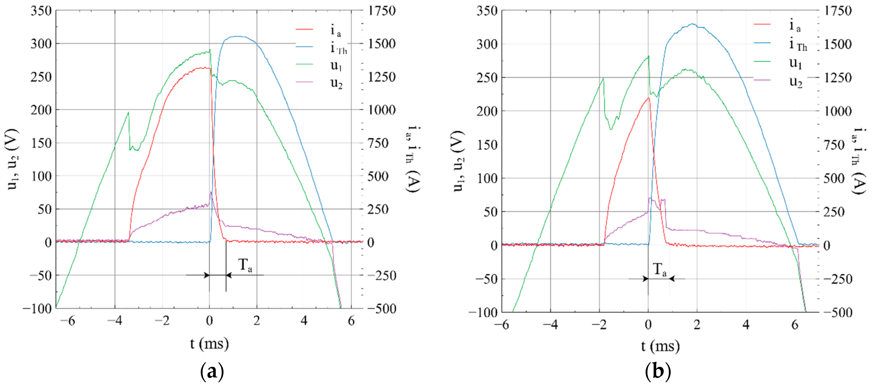
Figure 5a shows the elimination of the arc for the positive semi-wave of the flowing current. In turn, Figure 5b shows the elimination of the arc for the negative semi-wave of the flowing current. At the moment of arc ignition, the current and voltage in the branch of the arc source reach maximum values. The peak value of the current is 1600 A and the arc voltage at the moment of arc ignition is 80 V. When the explosion of a fusible element is detected by a detector, one of the thyristors of the arc eliminator is triggered. The voltage U2 decreases to about 25 V, i.e., to the voltage of the conductive semiconductor branch of the arc eliminator. The commutation of the current by the thyristor branch ITh causes the arc voltage Ua to be lowered below the minimum value of the burning arc, and as a result the arc is extinguished and the Ia current is reduced to zero. When the current passes through zero, the thyristor stops conducting and the current in the eliminator branch stops flowing. In the case of a positive half-wave of supply voltage, the arc time Ta from the moment of electric arc detection to taking over the full conduction through the thyristor in branch AE is 0.65 ms. In turn, in the case of a negative half-wave of the supply voltage, the arc time Ta is 0.52 ms.
When analyzing the voltage waveform on the U2 arc generator electrodes, it can be interpreted in the following way: at the moment of the arc fault, this waveform is shown by the voltage on the arc. However, at the moment when the arc eliminator is activated, this waveform represents voltage on the conductive thyristors. In turn, when the arc is extinguished and the thyristors are not conducting, it represents the voltage of the mains supply.
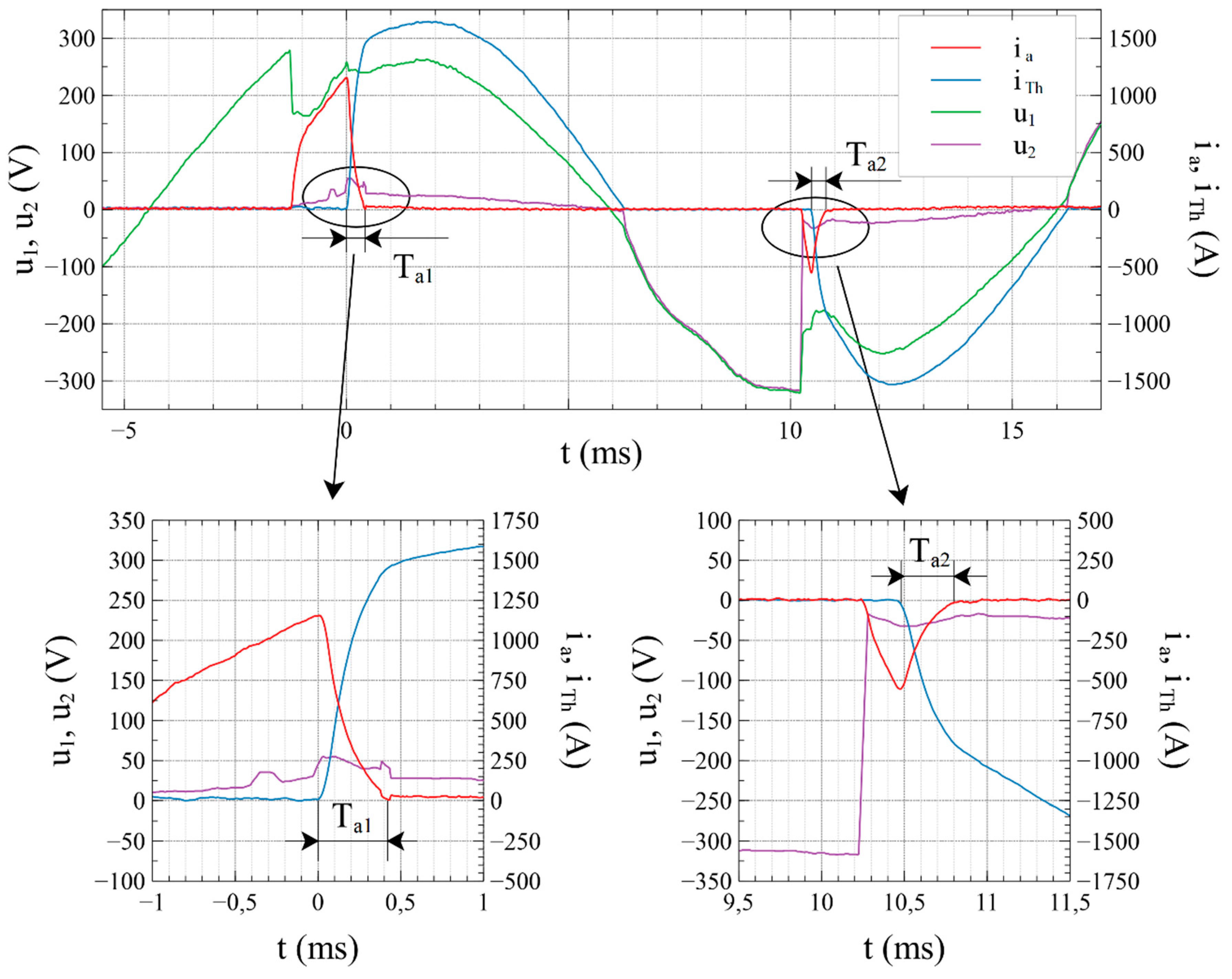
Figure 6 shows the course of arc ignitions in the positive and negative half-wave of the supply voltage together with enlarged pieces for each of the ignitions. The first arc ignition, initiated by the disintegration of the fusible element, occurs during a positive half-wave of the supply voltage. The elapsing time, from the moment of arc detection to the complete electric conduction over of the current conductivity by the Th1 thyristor, is 0.42 ms. When the current passes through zero, the conductive thyristor of the arc eliminator is switched off. Because of favorable conditions of electric arc formation, in the negative half-wave of power supply voltage the gap between electrodes is broken and another electric arc ignition occurs. The current in the branch affected by the arc fault disappears after 0.32 ms from the moment of detection and after triggering the Th2 thyristor in the branch of the arc eliminator.
Figure 7 shows the waveforms of currents and voltages recorded with variable regulatory inductance LR ranging from 5 µH to 426 µH. The increase in serial inductance of LR extends the time needed to turn off the arc. The term “arc extinguishing time Ta” should be understood as the interval from the moment of taking over the conductivity by the bypassing thyristor branch to the moment of current disappearance in the branch affected by the fault arc.
Analyzing Figure 7e, it can be seen that the arc ignition occurs in a positive half-wave of the supply voltage. Activation of the arc eliminator causes arc extinguishing in time Ta = 4.6 ms. Residues of the heated metallic material of the fuse excite the arc detector and the AE system reactivates again for a negative half-wave of the supply voltage. Thyristor Th1 conducts during the positive half-wave of the supply voltage, and thyristor Th2 takes over the conduction for the negative half-wave. The ITh current is the sum of the currents of the thyristor branches.
The inductance of the power supply network resulting from the measured impedance of the short circuit loop is 148 µH. Figure 7f shows the situation in which the serial regulatory inductance LR is three times as high as the inductance of the supply network. With such a large LR value, the arc will not be put out even when the supply voltage goes through zero and then changes to the opposite sign. The arc is extinguished in the second half-wave of the flowing current after 4.6 ms from the moment of its detection. This is because the value of current in the arc branch decreases exponentially and the increase in inductance increases the value of the time constant.
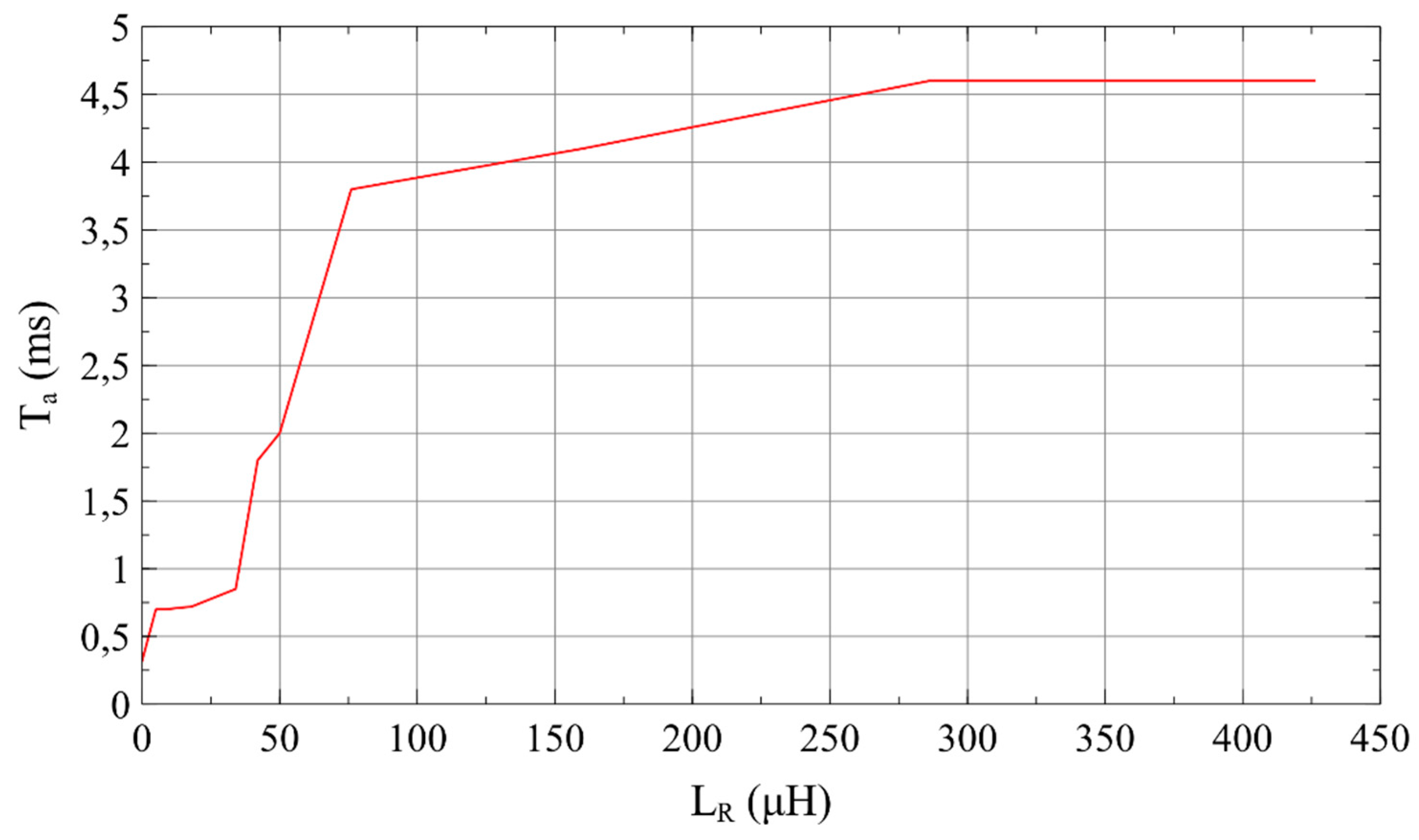
Table 2 shows the elimination times of the electric arc for variable arc current regulation parameters. It shows that the inductive nature of the circuit extends the time of full commutation of the current through the bypass branch. In addition, it can also be noted that with the increase in serial inductance in the arc branch, the arc time increases its value. It means that the time needed to effectively extinguish the arc is increased. It is therefore advisable to place the arc eliminator as close as possible to the protected device or to minimize the inductance of the line feeding the receiver.
Figure 8 shows a graphical representation of the results in Table 2. The dependence of the influence of serial inductance with arc on the value of arc time is shown. Activation of the arc eliminator in time up to 0.7 ms can be observed for LR inductance in the range from 0 µH to 34 µH. The next LR increase to 160 μH causes a rapid increase of arc time from 0.7 ms to 4.1 ms. After exceeding 160 μH, you can see a clear stabilization of arc time at the level of 4.6 ms.
4. Discussion
The available literature contains little work addressing the use of controlled semiconductor devices to eliminate electric arc and reduce short-circuit effects in electrical power circuits. Authors Zhang and others in reference [10] stated that a thyristor can work as an arc eliminator in circuits of a resistive or capacitive-resistance character. Based on their research, they concluded that the arc eliminator would not fulfill its task (quick elimination of the arc) in inductive circuits or in a situation where the arc is formed at a large distance from the location of the arc eliminator. Their assumption may be correct in a situation where the protected object is powered from capacitor banks, which results in a single half-wave of current starting in the amplitude of the supply voltage. The authors of this paper, carrying out a series of tests for variable inductance of the circuit supplied from the AC power grid, demonstrated the effectiveness of the electric arc eliminator both in resistive and inductive circuits. An increase in load inductance extends the time of arc eliminator activation but does not disqualify it as an arc protection device. It should be noted that in the context of protecting distant objects powered from low voltage AC power networks, the resistance of the circuit significantly exceeds its reactance. At the current stage of research, thyristors parameters, stemming from diversified technologies of their production, including, for example conduction voltage (several volts), are less important from the point of view of extinguishing an electric arc with a voltage exceeding 20 V. Diversified switching times for thyristors can be an optimization parameter, but are less important for the very nature of the eliminator operation.
5. Conclusions
The object of the above experiments was to check the possibility of using two oppositely connected thyristors as an emergency arc eliminator (AE). The semiconductor bypass system allows very fast bypassing of an electric circuit affected by arc disturbance, aimed at creating an alternative, privileged path for the current flow. In this way, the resulting electric arc is immediately eliminated. If the arcing fault occurred before reaching the maximum value of the flowing current, the elimination time of the arc fault affects the amplitude of the current in the affected branch. The shortening of the arc fault duration will reduce the amplitude of the fault current and the value of the arc energy released.
Experimental research has shown that in circuits with predominant resistance in relation to reactance, two oppositely connected thyristors can act as an arc eliminator, which will extinguish the arc in less than 0.7 ms. The work of thyristors as arc eliminators becomes more difficult in circuits where high inductance occurs between the power source and the place of emergence of the fault arc. The arc extinguishing time increases with the increase of serial inductivity to the value of 4.6 ms. Despite the large serial inductance of the object affected by the arc disturbance and the significant extension of the time needed to extinguish the arc, the arc eliminator fulfills its purpose, even if the longer arc burning time causes its re-ignition in the next half-wave of electricity.
An interesting area for observation may be the work of the arc eliminator in a configuration similar to autoreclosing known in protection automation (automatic reclosed). At the moment of the arc detection, the eliminator thyristors are triggered, and the arc is extinguished. After the disappearance of arc interference, the thyristors cease to conduct in the next half-wave of current, and the voltage at the receiver terminals reaches the value of the mains voltage. In such cases, quick elimination of the arc does not trigger the main power switch.
Author Contributions
Section 1 was prepared by K.N. and G.D. Section 2 (Thyristor arc fault Eliminator) was described by K.N. and J.J. All the authors jointly planned the experiment, described by K.N in Section 3. Section 4 was prepared by K.N., G.D. and J.J. The experiment was conducted by K.N. and J.J. Conclusions (Section 5) were prepared jointly by all the authors.
Funding
This research was funded by the Ministry of Science and Higher Education, grant number 04/41/SBAD/4408.
Conflicts of Interest
The authors declare no conflict of interest.
Nomenclatures
| Abbreviations | |
| AE | arc eliminator |
| AC | power source (Alternating Current) |
| Tr | transformer |
| CB | circuit breaker |
| Th1, Th2 | thyristors |
| Parameters | |
| RkQ | resistance of the power system |
| RTr | resistance of the transformer |
| RL | resistance of the power line |
| RLOAD | resistance of load |
| R | resistance of the fault circuit |
| RQ | the measured resistance of the short circuit loop |
| RR | serial resistance in the circuit of the arc generator |
| LkQ | inductance of the power system |
| LL | inductance of the power line |
| L | inductance of the fault circuit |
| LQ | the measured inductance of the short circuit loop |
| LR | serial inductance in the circuit of the arc generator |
| ZLoad | impedance of load |
| ZQ | the measured impedance of the short circuit loop |
| ZR | serial impedance in the circuit of the arc generator |
| XTr | reactance of the transformer |
| XLOAD | reactance of load |
| I, i | effective and instantaneous current values at characteristic points of the circuit |
| I”K | the effective value of the initial short circuit current |
| Ia | current in the branch of the arc source |
| ITh | current in the thyristor branch |
| iAC | alternating-current component |
| iDC | direct-current component |
| ia | the instantaneous value of arc current |
| U, u | effective and instantaneous voltage values at characteristic points of the circuit |
| Um | supply voltage amplitude |
| Ua | the value of the arc voltage |
| U1 | supply voltage |
| U2 | voltage on the electrodes of the arc source |
| ua | the instantaneous value of the arc voltage |
| u1 | the instantaneous value of the supply voltage |
| u2 | the instantaneous voltage value on the electrodes of the arc source |
| ω | pulsation voltage values or current values |
| ψ | phase angle of voltage at the moment of short circuit |
| φz | the short circuit impedance argument |
| Wa | arc energy |
| Ta | the duration of the electric arc |
References
- Yang, L.; Qiu, W.; Huang, J.; Hao, Y.; Fu, M.; Hou, S.; Li, L. Comparison of conductor-temperature calculations based on different radial-position-temperature detections for high-voltage power cable. Energies 2018, 11, 117. [Google Scholar] [CrossRef]
- Lu, Q.; Ye, Z.; Zhang, Y.; Wang, T.; Gao, Z. Analysis of the effects of arc volt-ampere characteristics on different loads and detection methods of series arc faults. Energies 2019, 12, 323. [Google Scholar] [CrossRef]
- Yang, Q.; Wang, J.; Sima, W.; Chen, L.; Yuan, T. Mixed over-voltage decomposition using atomic decompositions based on a damped sinusoids atom dictionary. Energies 2011, 4, 1410–1427. [Google Scholar] [CrossRef]
- Yin, Z.; Wang, L.; Zhang, Y.; Gao, Y. A novel arc fault detection method integrated random forest, improved multi-scale permutation entropy and wavelet packet transform. Electronics 2019, 8, 396. [Google Scholar] [CrossRef]
- Whittingham, R.B. The Blame Machine. Why Human Error Causes Accidents, 1st ed.; Elsevier Butterworth Heinemann Linacre House: Burlington, MA, USA, 2004; pp. 237–242. [Google Scholar]
- Kay, J.A.; Kumpulainen, L. Maximizing protection by minimizing arcing times in medium-voltage systems. IEEE Tech. Ind. Appl. 2013, 49, 1920–1927. [Google Scholar] [CrossRef]
- Dugan, T. Reducing the flash hazard. IEEE Ind. Appl. Mag. 2007, 13, 51–58. [Google Scholar] [CrossRef]
- Hodder, M.; Vilchek, W.; Croyle, F.; McCue, D. Practical arc-flash reduction. IEEE Ind. Appl. Mag. 2006, 12, 22–29. [Google Scholar] [CrossRef]
- Hussain, G.A. Method for Arc-Flash Protection in Medium Voltage and Low Voltage Switchgear. Ph.D. Thesis, Aalto University, Helsinki, Finland, 2015. [Google Scholar]
- Zhang, Z.; Ma, B.; Friberg, A. Thyristor working as arc eliminator protecting electrical apparatus in low voltage power system. In Proceedings of the IEEE International Conference on Industrial Technology (ICIT), Seville, Spain, 17–19 March 2015; pp. 1216–1219. [Google Scholar]
- Yang, K.; Zhang, R.; Yang, J.; Liu, C.; Chen, S.; Zhang, F. A novel arc fault detector for early detection of electrical fires. Sensors 2016, 16, 500. [Google Scholar] [CrossRef] [PubMed]
- Boren, S.G. Intelligence Automatic Bypass for a Motor Control Device Fault. U.S. Patent US20040252423A1, 16 December 2004. [Google Scholar]
- Bhargava, B.; Haas, R.G. Thyristor protected series capacitors project at Southern California Edison Co. In Proceedings of the IEEE Power Engineering Society Summer Meeting (PESS), Chicago, IL, USA, 21–25 July 2002; pp. 241–246. [Google Scholar]
- Pulvirenti, F.; La Scala, A.; Pennisi, S. Low voltage-drop bypass switch for photovoltaic applications. In Proceeding of the IEEE International Symposium on Circuits and Systems (ISCAS), Seoul, Korea, 20–23 May 2012; pp. 2283–2286. [Google Scholar]
- Backman, M.; Demetriades, G.; Shukla, A. Hybrid Circuit Breaker. European Patent Patent No. EP2465129B1, 24 April 2013. [Google Scholar]
- Liu, L.; Zhuang, C.; Wang, Z.; Jiang, Z.; Wu, J.; Chen, B. A hybrid DC vacuum circuit breaker for medium voltage: Principle and first measurements. IEEE Tech. Power Deliv. 2015, 30, 2096–2101. [Google Scholar] [CrossRef]
- Naidu, M.; Schoepf, T.J.; Gopalakrishnan, S. Arc fault detection scheme for 42-V automotive DS networks using current shunt. IEEE T. Power Electr. 2006, 21, 633–639. [Google Scholar] [CrossRef]
- Hatsagi, B. Electromagnetic Modelling and Testing of a Thomson Coil Based Actuator. Master’s Thesis, KTH Royal Institute of Technology, Stockholm, Sweden, 2017. [Google Scholar]
- Pei, X.; Smith, A.C.; Shuttleworth, R.; Vilchis-Rodriguez, D.S.; Barnes, M. Fast operating moving coil actuator for vacuum interrupter. IEEE Tech. Energy Convers. 2017, 32, 931–940. [Google Scholar] [CrossRef]
- Bissal, A.; Eriksson, A.; Magnusson, J.; Engdahl, G. Hybrid multi-physics modeling of an ultra-fast electro-mechanical actuator. Actuators 2015, 4, 314–335. [Google Scholar] [CrossRef]
- Peng, C.; Husain, I.; Huang, A.Q. Evaluation of design variables in Thompson coil based operating mechanisms for ultra-fast opening in hybrid AC and DC circuit breakers. In Proceedings of the IEEE Applied Power Electronics Conference and Exposition (APEC), Charlotte, NC, USA, 15–19 March 2015; pp. 2325–2332. [Google Scholar]
- Oeberg, A.; Chimento, F.; Qin, J.; Wang, L.; Jeppsson, O. Bypass Switch Assembly. U.S. Patent US9099268B2, 4 August 2015. [Google Scholar]
- Tirmizi, A.A. Pyrotechnic Circuit Breaker. U.S. Patent US7239225B2, 3 July 2007. [Google Scholar]
- Partyka, R. Investigation of Fault-Arcs Effects in Enclosed Switchgear, 1st ed.; Gdansk University of Technology Publisher: Gdansk, Poland, 2008; pp. 22–96. (In Polish) [Google Scholar]
- The Catalogue of Power Semiconductor Devices. Thyristors. Available online: http://delibra.bg.polsl.pl/Content/30503/BCPS_34289_1986_Tyrystory---przyrzad.pdf (accessed on 3 July 2019).
Figure 1.
Scheme of using the Arc Eliminator to protect low voltage network devices; RkQ—resistance of the power system [Ω], LkQ—inductance of the power system [H], Tr—transformer with resistance RTr and reactance XTr [Ω], RL—resistance of the power line [Ω], LL—inductance of the power line [H], CB—circuit breaker, ZLoad—load with resistance RLOAD and reactance XLOAD [Ω], AE—arc eliminator, I, i—effective and instantaneous current values at characteristic points of the circuit, U, u—effective and instantaneous voltage values at characteristic points of the circuit.

Figure 2.
Arc eliminator test circuit (AE).

Figure 3.
Part of the arc eliminator test circuit (AE) with marked measurement points: 1—supply voltage (U1), 2—voltage on the electrodes of the arc source (U2), 3—current in the branch of the arc source (Ia), 4—current in the thyristor branch (ITh).
Figure 3.
Part of the arc eliminator test circuit (AE) with marked measurement points: 1—supply voltage (U1), 2—voltage on the electrodes of the arc source (U2), 3—current in the branch of the arc source (Ia), 4—current in the thyristor branch (ITh).
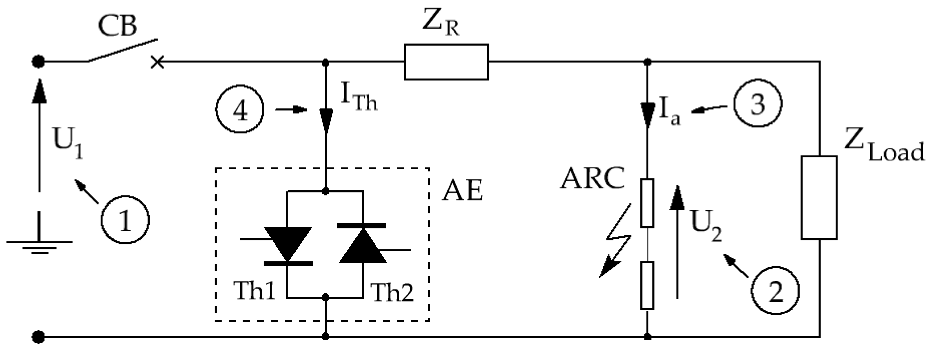
Figure 4.
Arc current waveforms (ia) and supply voltage (u1) and voltage measured on the arc source electrodes (u2) in a circuit in which thyristor Th1 and thyristor Th2 are not triggered: (a) LR = 0 μH, arc time Ta = 47 ms; (b) LR = 163 μH, arc time Ta = 43.5 ms.
Figure 4.
Arc current waveforms (ia) and supply voltage (u1) and voltage measured on the arc source electrodes (u2) in a circuit in which thyristor Th1 and thyristor Th2 are not triggered: (a) LR = 0 μH, arc time Ta = 47 ms; (b) LR = 163 μH, arc time Ta = 43.5 ms.

Figure 5.
Current waveforms in the load (ia) branch and current in the thyristor branch (iTh) and supply voltage (u1) and voltage measured on the arc source electrodes (u2) in the arc eliminator system: (a) Arc eliminator switched on when an electric arc flash was detected for a positive half-wave of flowing current, LR = 0 μH, arc time Ta = 0.72 ms; (b) Arc eliminator switched on when an electric arc flash was detected for a negative half-wave of flowing current LR = 0 μH, arc time Ta = 0.7 ms.
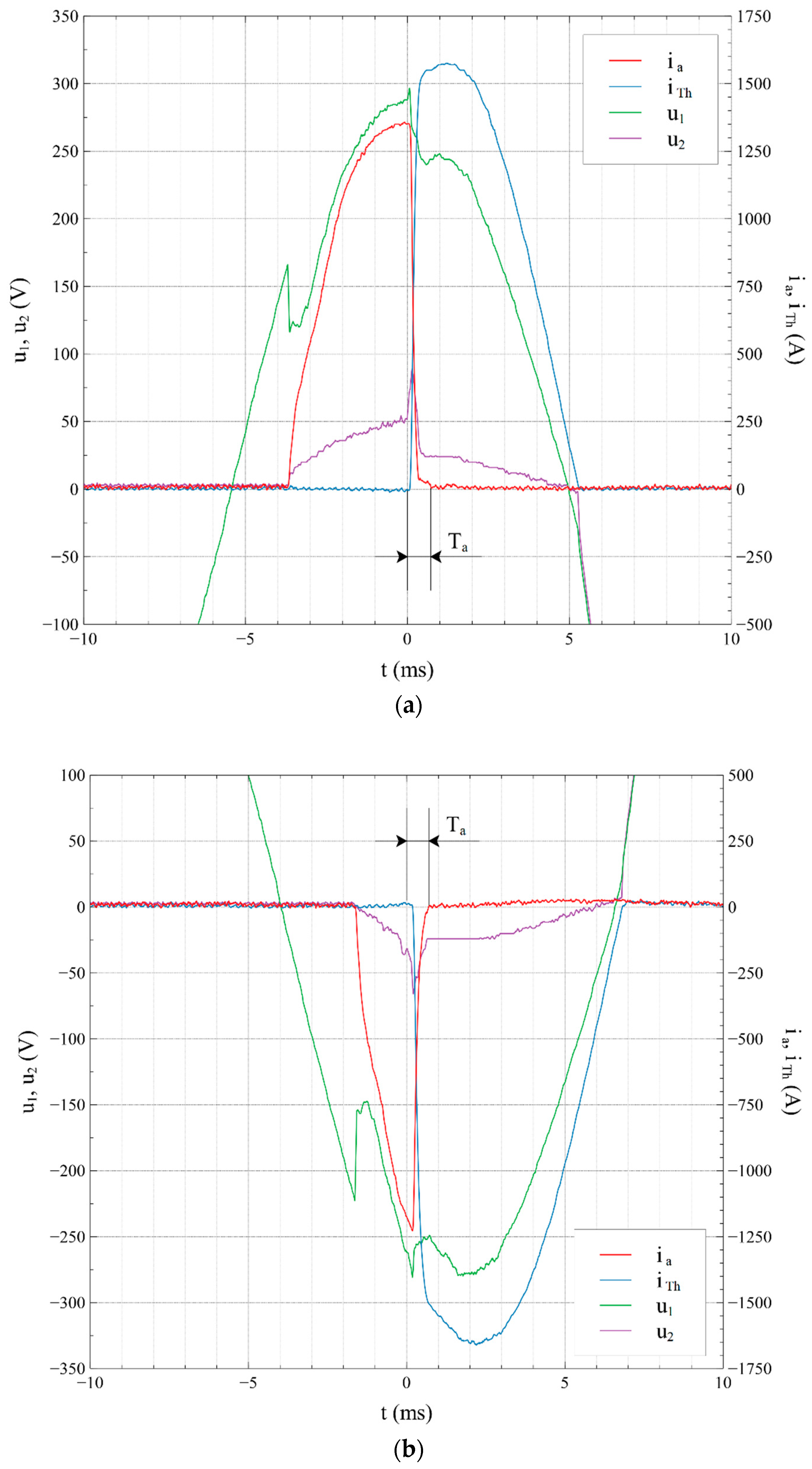
Figure 6.
Current waveforms in the load branch (Ia), current in the thyristor branch (iTh), supply voltage (u1) and voltage measured on the arc source electrodes (u2) at subsequent arc ignitions (Ta1 = 0.42 ms, Ta2 = 0.32 ms).
Figure 6.
Current waveforms in the load branch (Ia), current in the thyristor branch (iTh), supply voltage (u1) and voltage measured on the arc source electrodes (u2) at subsequent arc ignitions (Ta1 = 0.42 ms, Ta2 = 0.32 ms).

Figure 7.
Current waveforms in the arc branch (ia) and current in the thyristor branch (iTh) and supply voltage (u1) and voltage measured on the arc source electrodes (u2) for various parameters of the current: (a) LR = 5 μH, Ta = 0.7 ms; (b) LR = 34 μH, Ta = 0.85 ms; (c) LR = 76 μH, Ta = 3.8 ms; (d) LR = 160 μH, Ta = 4.1 ms; (e) LR = 286 μH, Ta = 4.6 ms; (f) LR = 426 μH, Ta = 4.6 ms.

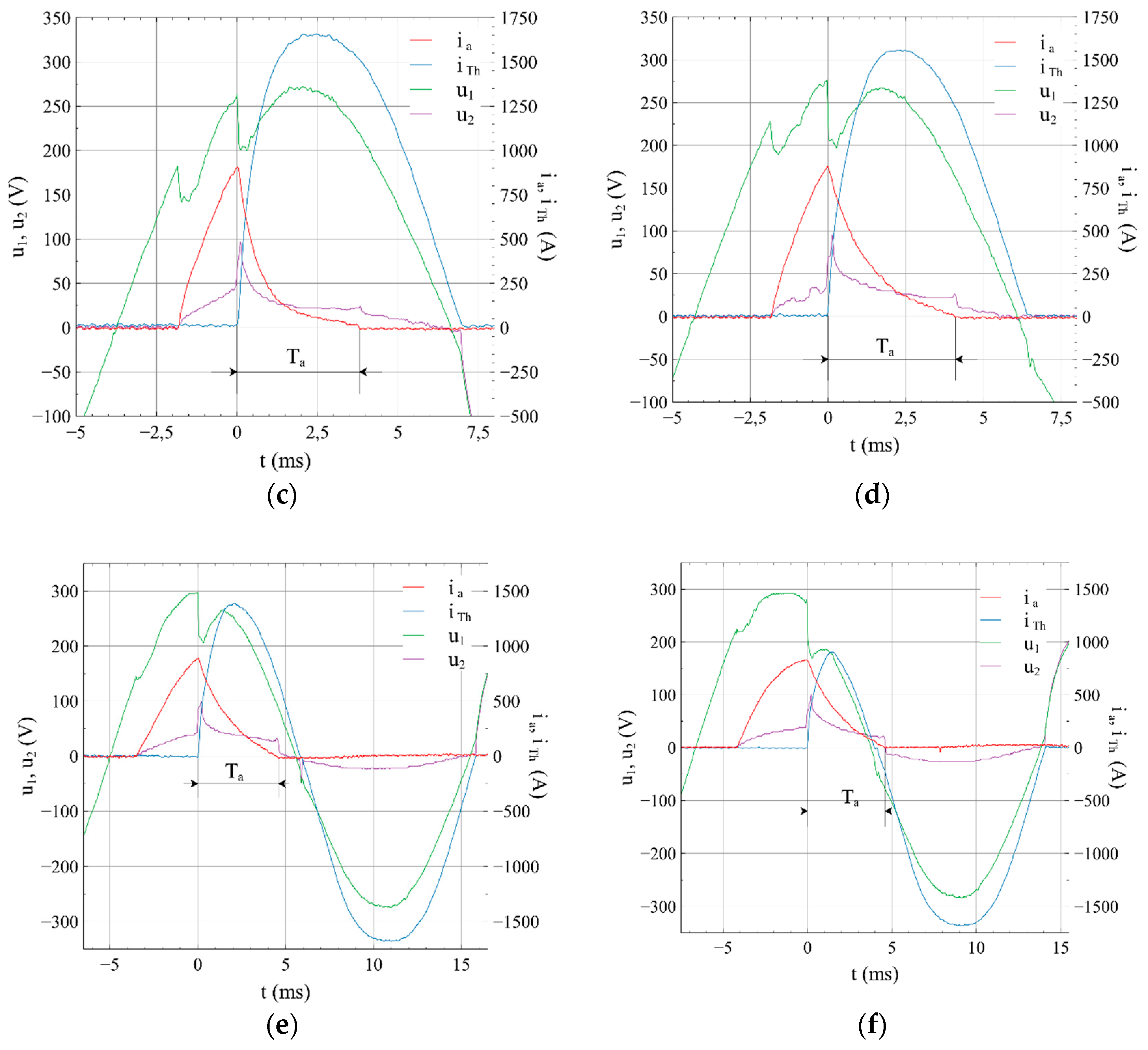
Figure 8.
The dependence of series inductance in the LR arc branch from the arc time Ta.

Table 1.
Parameters of the Unitra-Lamina TR51-80-12-76 thyristors (Adapted from [25]).
Table 1.
Parameters of the Unitra-Lamina TR51-80-12-76 thyristors (Adapted from [25]).
| Parameter | Value |
|---|---|
| Surge current ITSM [A] | 1260 |
| Repetitive peak reverse voltage URRM [V] | 1200 |
| I2t value [A2s] | 7900 |
| Rate of rise of on-state current repetitive di/dt [A/µs] | 50 |
| Critical rate of raise of off-state voltage du/dt [V/µs] | 1000 |
| Circuit commutated turn-off time (typical) tq [µs] | 20 |
| Turn-on time (typical) tON [μs] | 4 |
| Operating junction temperature Ti [°C] | 125 |
Table 2.
Effect of serial inductance of arc branches on arc time.
| No | Load LR [μH] | Arc Time Ta [ms] |
|---|---|---|
| 1 | 0 | 0.32–0.72 |
| 2 | 5 | 0.7 |
| 3 | 8.4 | 0.7 |
| 4 | 18 | 0.72 |
| 5 | 34 | 0.85 |
| 6 | 42 | 1.8 |
| 7 | 50 | 2 |
| 8 | 76 | 3.8 |
| 9 | 160 | 4.1 |
| 10 | 286 | 4.6 |
| 11 | 426 | 4.6 |
© 2019 by the authors. Licensee MDPI, Basel, Switzerland. This article is an open access article distributed under the terms and conditions of the Creative Commons Attribution (CC BY) license (http://creativecommons.org/licenses/by/4.0/).
Share and Cite
MDPI and ACS Style
Nowak, K.; Janiszewski, J.; Dombek, G. Thyristor Arc Eliminator for Protection of Low Voltage Electrical Equipment. Energies 2019, 12, 2749. https://doi.org/10.3390/en12142749
AMA Style
Nowak K, Janiszewski J, Dombek G. Thyristor Arc Eliminator for Protection of Low Voltage Electrical Equipment. Energies. 2019; 12(14):2749. https://doi.org/10.3390/en12142749
Chicago/Turabian StyleNowak, Karol, Jerzy Janiszewski, and Grzegorz Dombek. 2019. "Thyristor Arc Eliminator for Protection of Low Voltage Electrical Equipment" Energies 12, no. 14: 2749. https://doi.org/10.3390/en12142749
Note that from the first issue of 2016, this journal uses article numbers instead of page numbers. See further details here.