Study on the Mechanism of Ionic Stabilizers on Shale Gas Reservoir Mechanics in Northwestern Hunan
by
 , ,
, ,
Pinghe Sun
1,2 ,
,
Junyi Zhu
1,2,
Binkui Zhao
1,2,
Xinxin Zhang
1,2,*,
Han Cao
1,2,*,
Mingjin Tian
3,
Meng Han
1,2 and
Weisheng Liu
1,2 1
Key Laboratory of Metallogenic Prediction of Nonferrous Metals and Geological Environment Monitoring, Ministry of Education, Changsha 410083, China
2
School of Geosciences and Info–physics, Central South University, Changsha 410083, China
3
Hunan Provincial Communications Planning, Survey and Design Institute Co., Ltd., Hunan Changsha 410008, China
*
Authors to whom correspondence should be addressed.
Energies 2019, 12(12), 2453; https://doi.org/10.3390/en12122453
Submission received: 27 April 2019
/
Revised: 10 June 2019
/
Accepted: 24 June 2019
/
Published: 25 June 2019
(This article belongs to the Special Issue Shale Oil and Shale Gas Resources)
Abstract
:The shale of the lower Cambrian Niutitang formation in northwestern Hunan is an ideal reservoir for shale gas. There is a close connection between borehole stability and drilling fluid in shale gas drilling. Ionic stabilizer is a new type of stratum consolidation agent that inhibits the hydration expansion of clay minerals and improves mechanical strength of the borehole. The traditional idea of pore wall protection is to use drilling fluid additives to prevent shale from interacting with water. However, ionic stabilizer can change the hydrophilic of clay minerals in shale, making the particles become hydrophobic and dense, therefore, the formation stability can be enhanced simultaneously. The material used in this paper is different from the normal ionic stabilizer, some chemical bonds that have been changed in the new material called enhanced normality ionic (ENI) stabilizer. This paper utilized the shale samples those obtained from Niutitang formation to study the connection between ENI and the mechanical properties of shale. Mechanical tests and microscopic pore tests were performed on different samples which were soaked in water and the ENI with different concentrations. It has been found through tests that ENI can inhibit the development of shale pores, and as the concentration increases, the inhibition increases. In addition, as the ENI concentration increases, the uniaxial compressive strength and Young’s modulus of the shale increase, and the ratio of stability coefficients decreases. It can be concluded that the ENI can improve the mechanical strength of carbon shale, and prevent the development of rock damage. Moreover, it can improve the ability of rock to resist damage, and enhance borehole stability initiatively.
1. Introduction
Shale gas is an unconventional energy source with great potential for exploration and development. The black carbonaceous shale of the lower Cambrian Niutitang formation is one of the key main targets for the exploration and development of shale gas in the future in China [1,2,3]. It is widely distributed in northwestern Hunan. The shale in this area has thick sediment and high abundance of organic matter, which has abundant shale gas resources [4,5]. The interaction between drilling fluid and shale leads to wellbore instability, which has been a concern in shale gas development [6,7,8,9]. Furthermore, the productivity of the wells decreases due to this instability, which also increases the drilling cost [10]. In order to improve the stability of the borehole, scholars added some drilling additives to inhibit shale hydration. For example, some scholars used polymer to reduce water loss and inhibited its hydration expansion in shale drilling [11,12,13,14]. Some scholars use nano-compounds to maintain drilling stability to seal small holes in shale [15,16,17]. Other scholars utilized shale inhibitors such as surfactant, polyether and ammonium salt to improve the stability of the pore walls [18,19,20]. These additives improved the stability of the pore walls by preventing the shale from interacting with water. However, these are some passive defense modes. In fact, there is a better way to enhance shale strength and improve borehole wall stability actively, that is, by using ionic stabilizers.
Ionic stabilizer is one kind of environmental engineering materials, which is composed of inorganic and organic materials [21]. Ionic stabilizer can change the hydrophilic of cations in clay minerals [22]. In addition, it can reduce the thickness of bound water film and enhance the stratum overall strength [23,24,25,26]. It emerged in the 1970s and has been widely used in various industries, and currently in civil engineering. However, the application of ionic stabilizer in shale drilling is still rare. There is a close connection between borehole stability and drilling fluid in shale gas drilling [27,28,29]. The traditional borehole stability protection idea is to reduce the drilling fluid pressure and stratum intrusion [12,30]. However, ionic stabilizer can change the hydrophilic of clay minerals in shale, making the particles become hydrophobic and dense, therefore, the formation stability can be enhanced. The material used in this paper is different from the normal ionic stabilizer, some chemical bonds that have been changed in the new material called enhanced normality ionic (ENI) stabilizer. This paper utilized the shale that obtained from the Niutitang formation to explore the connection between ENI and the mechanical properties of shale.
Mechanical tests and microscopic pore tests were selected as two different mechanical methods in this study [31,32,33]. Uniaxial compression test and pore characteristics observation were performed on different samples which were soaked in water and the ENI with different concentrations. The mechanism of ENI on the carbonaceous shale samples were analyzed based on the test results.
2. Materials and Methods
2.1. Materials
ENI used in this study was light yellow, mainly composed of a petroleum sulfonated agent, modified sodium silicate, and a modified polymer surface active agent. It can decompose the clay mineral and nonclay particles in the stratum. Moreover, it can recrystallize the clay mineral particles and reduce the invasion of filtrate relying on making use of bonding and winding between polymer compounds and leaving the particles hydrophobic and dense [34,35].
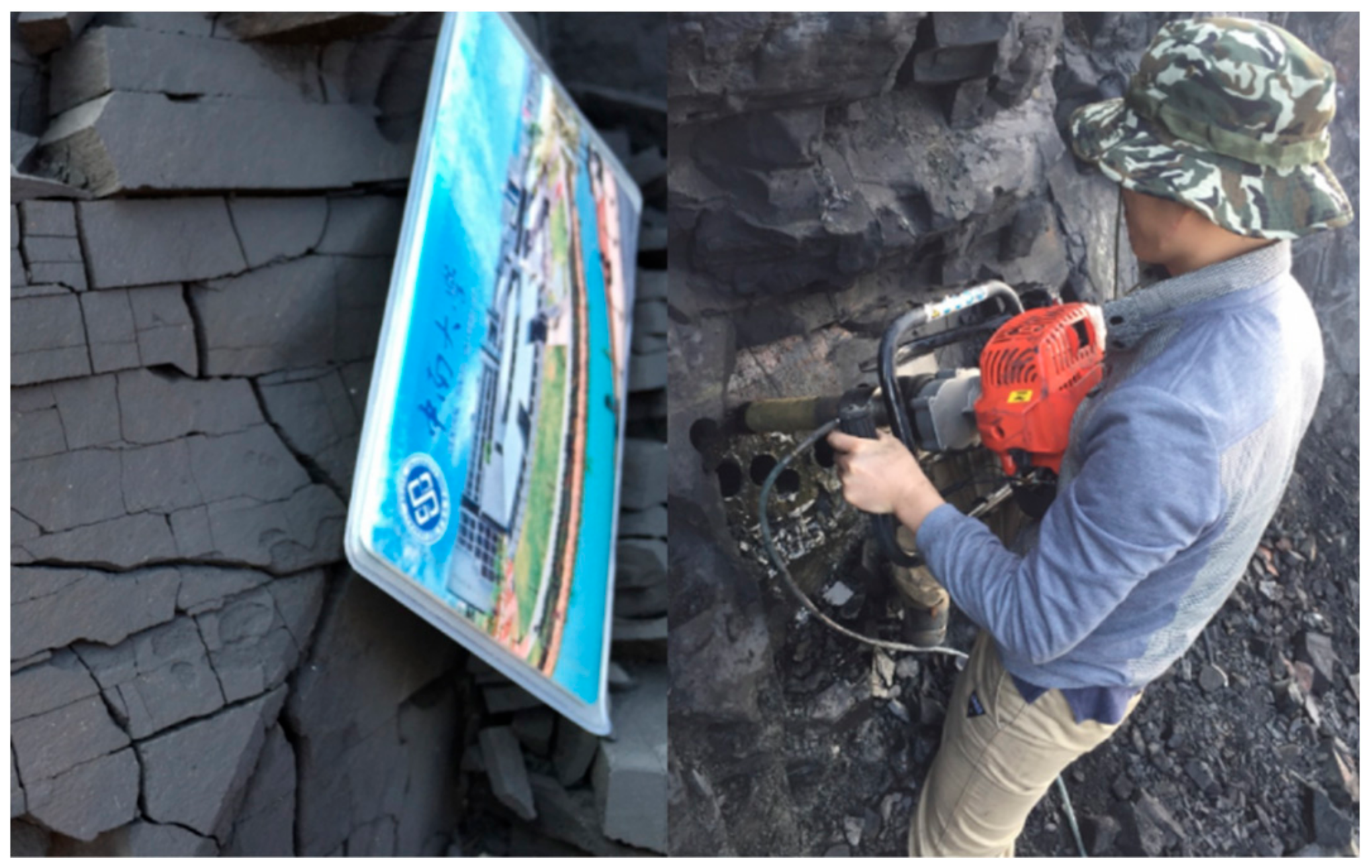
The black carbonaceous shale samples utilized in this paper were obtained from the lower Cambrian Niutitang formation in northwestern Hunan. Most shale gas can be explored in this stratum. Reservoir samples with diameter 50 mm (Φ50) and length 100 mm were obtained by the small modified portable drilling rig in the field (Figure 1). Other samples were cut into 15 × 10 × 5 mm in the lab. However, in order to eliminate the influence of man-made disturbance on rock samples, the intact samples were selected to perform in all experiments. Mineral composition of the shale was obtained by X–ray diffraction (XRD) analysis of rock sample fragments, and the results are indicated in Table 1. The results showed that clay minerals were mainly strong-expanded smectite. There was more than 25% smectite in the samples which indicates that these rocks were prone to changes in strength due to the hydration expansion.
2.2. Uniaxial Compression Test
Uniaxial compression tests were performed after immersing the samples in different concentrations of ENI. The ENI concentrations in the experiment were 0%, 1%, 2%, 3%, and 4%. The uniaxial compression deformation tests were carried out by a rock tensile splitting machine, and the dynamic static strain gauge was used for deformation monitoring at the same time. The shale samples in the experiment were immersed in different concentrations of ENI for 24 hours at constant temperature (25 ± 2 °C). Continuous loading was added by the rate of 0.5MPa/s. The data was recorded automatically until the samples were destroyed. The stress-strain curve was measured by the machine, and the uniaxial compressive strength (UCS) and Young’s modulus of the shale were calculated based on the curve.
2.3. Microscopic Pore Test
Microscopic pore tests were performed after immersing the samples in different concentrations of ENI. The ENI concentrations in the test were 0%, 1%, 2%, 3%, and 4%. Pore characteristics were analyzed by scanning electron microscope (SEM). SEM image information was processed by Photoshop and ImageJ2x image processing software. The ratio of fractal dimension and stability coefficient of shale were obtained by analysis and fitting.
2.3.1. Fractal Dimension
Fractal dimension is a measure of the irregularity of complex shapes. It can identify the quantitative description of the complexity and heterogeneity on pore structure [36]. The larger the fractal dimension, the higher the spatial geometric complexity of the pore shape and the rougher the sample surface. Therefore, the stability of shale can be evaluated by fractal dimension. Basic shape characteristic parameters such as area, perimeter of the shale sample can be obtained by processing the SEM image. Based on the definition of damage mechanics, fractal dimension can be calculated by perimeter and pore area as follows:
where C is the pore perimeter, the unit is mm, A is the pore area, the unit is mm2, I is the pore system fractal dimension, and b is a constant.
2.3.2. Ratio of Stability Coefficients
The relative damage variable can be defined as damage value according to the damage theory. Damage value is a "deterioration coefficient" that affects the rock mechanical properties seriously [37,38,39]. Pores and fractures in the shale reservoir will weaken the overall strength and reduce the stability. The smaller damage value is, the better physical and mechanical properties of rock are, and the better borehole stability is. Damage value can be calculated by the total micropores area and the bearing area of the shale sample as follows:
where: D is the damage value; Si is the sum of the area occupied by the micropores on the bearing surface of the rock sample, the unit is mm2; S0—the apparent bearing area of the rock sample, the unit is mm2.
The stability coefficient is an important indicator for evaluating borehole stability and rock strength. The smaller stability coefficient is, the better physical and mechanical properties of rock are, and the more borehole stability is. According to the deification of damage tolerance, the stability coefficient “F” can be calculated as follows:
The ratio of rock stability coefficients can be derived based on Equations (2) and (3), which is the ratio under the effect of different concentrations of ENI. The ratio of the stability coefficient Kn is calculated as follows:
where is the sum of the area occupied by micro–pores on the surface of the sample soaked in water, the unit is μm2; is the sum of the area occupied by micro–pores on the surface of the rock soaked by n%ENI, the unit is μm2; Kn is the ratio of water to n%ENI stability coefficient.
In order to determine the strength and stability of the shale sample under the influence of water and different concentrations of ENI, the ratio of the stability coefficient is an intuitive expression that can reflect pore, strength and stability properties. The smaller the value, the larger the difference between the two shale samples and the higher the intensity of the shale sample.
3. Results and Discussions
3.1. Uniaxial Compression Test
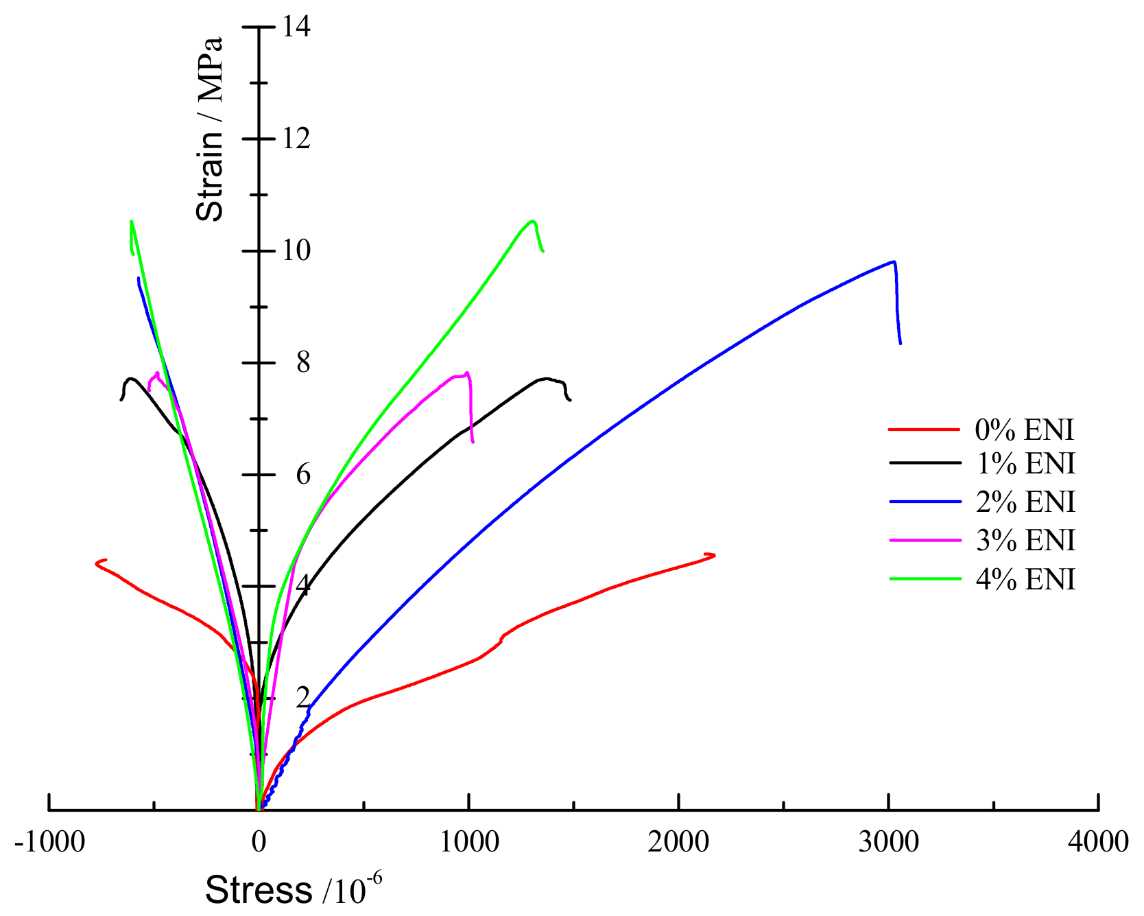
The relationship curves between axial compression stress–strain and radial strain are indicated in Figure 2. It was derived from the experimental data.
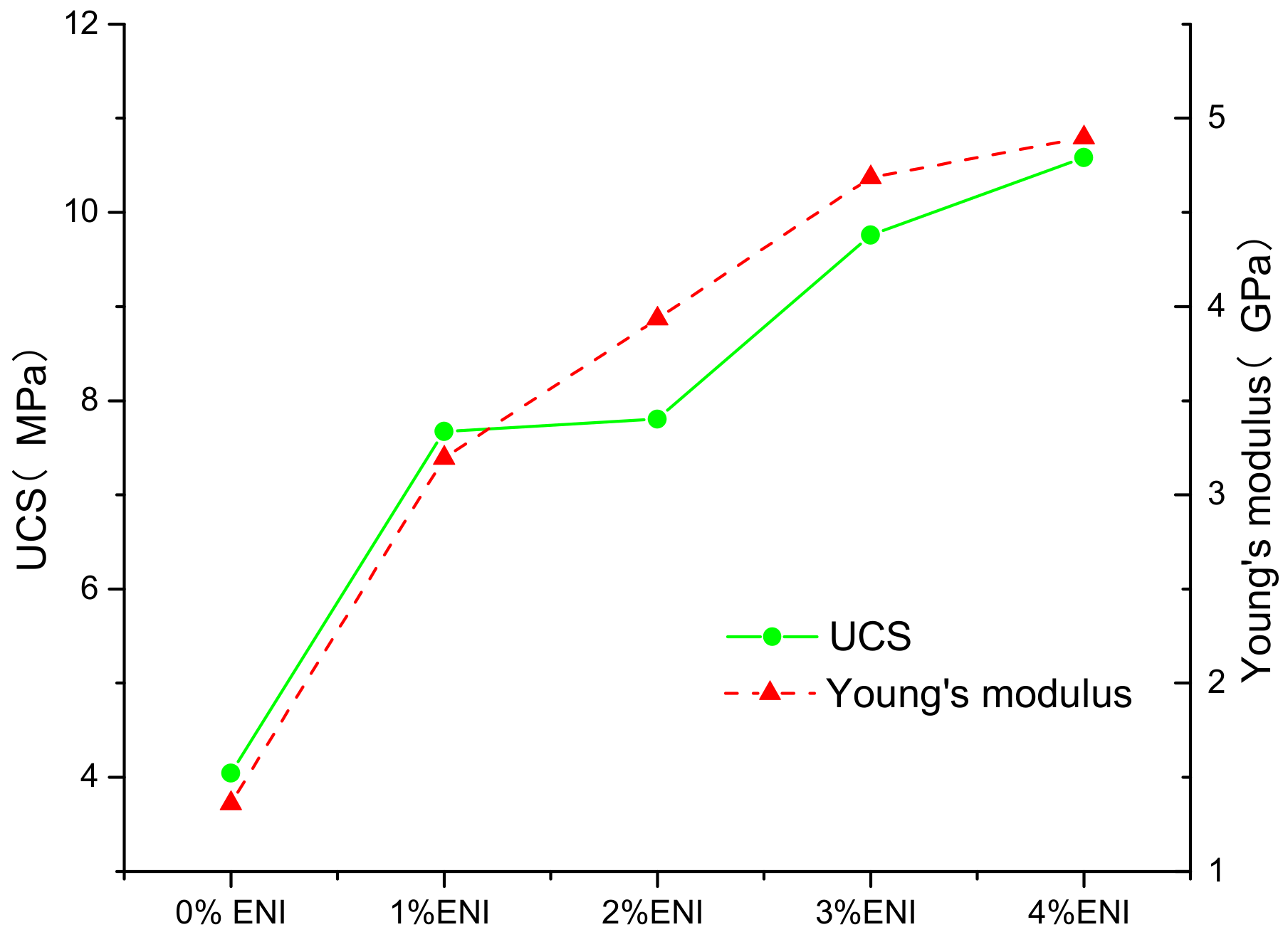
The UCS and Young’s modulus values (shown in Figure 3) of samples under the different concentrations of ENI were obtained through analysis and calculation. These results were based on the linear part of curve in Figure 2.
The results indicate that UCS was positively correlated with the concentration of ENI. When the ENI concentration was 0%, UCS reached the minimum, equal to 4.045MPa. However, when the ENI concentration was 4%, the UCS reached the maximum, equal to 10.583MPa, which was 2.61 times the minimum value. Simultaneously, the Young’s modulus was also positively correlated with ENI concentration. When the ENI concentration was 0%, Young’s modulus reached the minimum, equal to 1.361GPa. When the ENI concentration was 4%, its value reached the maximum, equal to 4.897GPa, which was 3.59 times the minimum value. The higher the ENI concentration is, the better the mechanical properties of the shale sample are. In addition, for these two parameters, the growth rate of Young’s modulus was greater than UCS when the ENI concentration increments were the same. This indicates that the inhibitory effect of ENI on shale hydration expansion is more effective than the increase of overall strength. This shows that ENI can enhance the borehole stability of shale gas drilling. As concentration of ENI increases, the curve gradually slows down, but no vertices appear. The curve indicates that as ENI concentration increases, UCS and Young’s modulus increase rate of the shale decreases. As one of the concerns, ENI suitable concentration problem needs to be solved in a future study.
3.2. Pore Characteristics
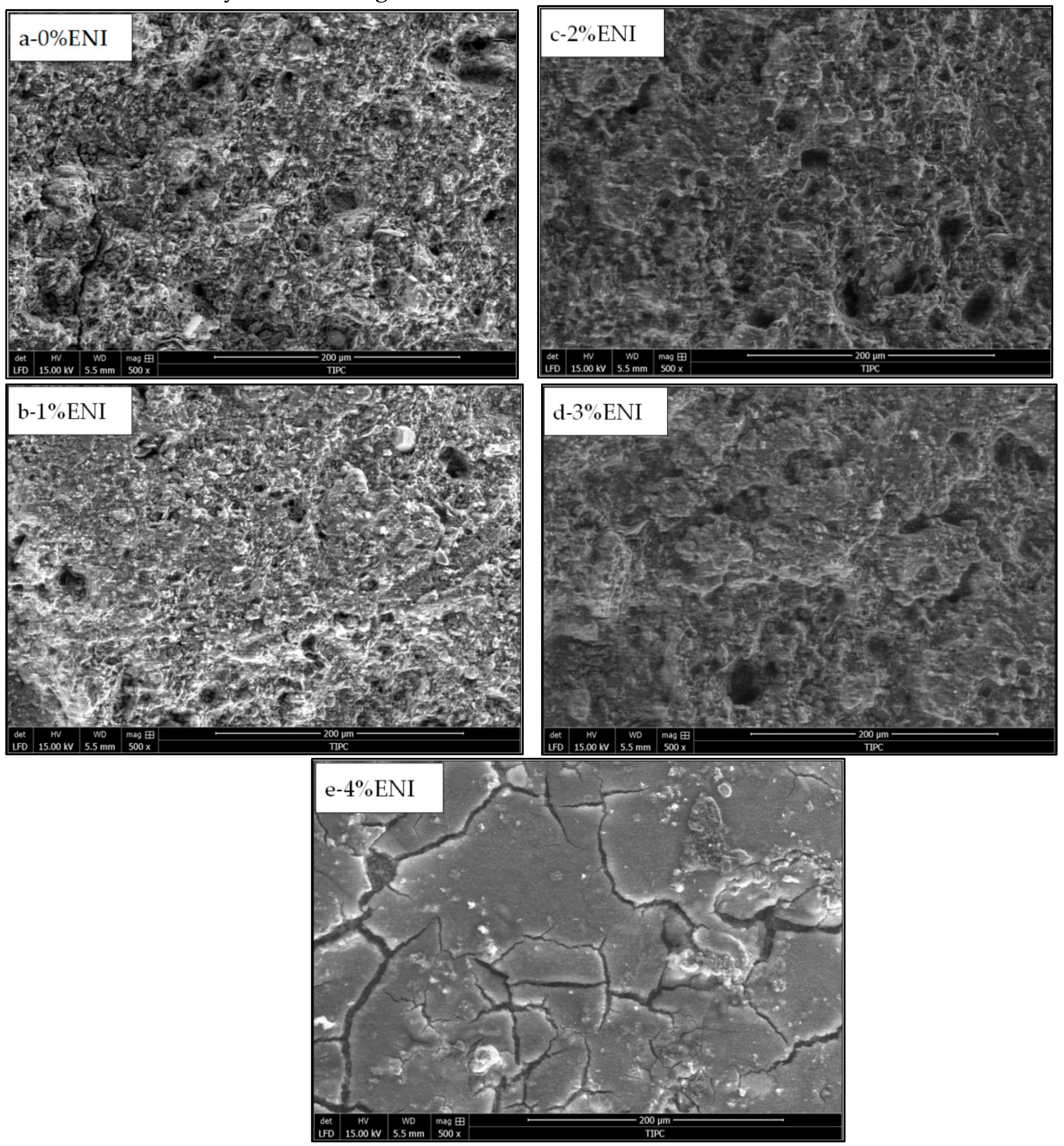
Other square samples (length 15 × wide 10 × height 5 mm) were immersed in different concentrations of ENI for 24 hours. Then the surface morphology of samples was analyzed by SEM images. SEM images are first chosen to address scaling issues when choosing samples for 2D and 3D volumetric analysis. The images’ microstructural information is indicated in Figure 4.
In order to obtain the quantitative information of shale pores and fissures, 500x magnification SEM images were processed by Photoshop and ImageJ2x. After smoothing, the resultant images, which appeared similar to the original photomicrograph but with a minimal background, were then converted to binary images by setting a threshold. In order to unify data, pore characteristics data of the rock samples were summarized. The average values of the pore area and perimeter of the shale sample under different concentrations of ENI were calculated from the summarized data (shown in Table 2).
The pore variation on shale sample surface under different conditions is clear when the qualitative observation of shale microscopic morphology is obtained in Figure 3. When water was immersed into the sample, its structure became very loose due to the extension of pores and cracks. Otherwise, with the increasing of ENI concentration, the pores and fractures in the same samples decrease and the rock surface becomes smooth gradually. For example, only a few pores can be seen on the surface of the sample after 4% ENI added from Figure 4e. At the same time, according to Table 2, as the ENI concentration increases, the pore area and perimeter in the sample decrease. This trend was similar to the SEM results, indicating that ENI can discourage the development of shale pore. In order to further study the relationship between ENI and the mechanical properties of shale, the ratio of fractal dimension to stability coefficient is obtained from the pore characteristic data. The ratio of the stability coefficients derived from the stability coefficients is affected by different concentration water and ENI.
3.2.1. Fractal Dimension
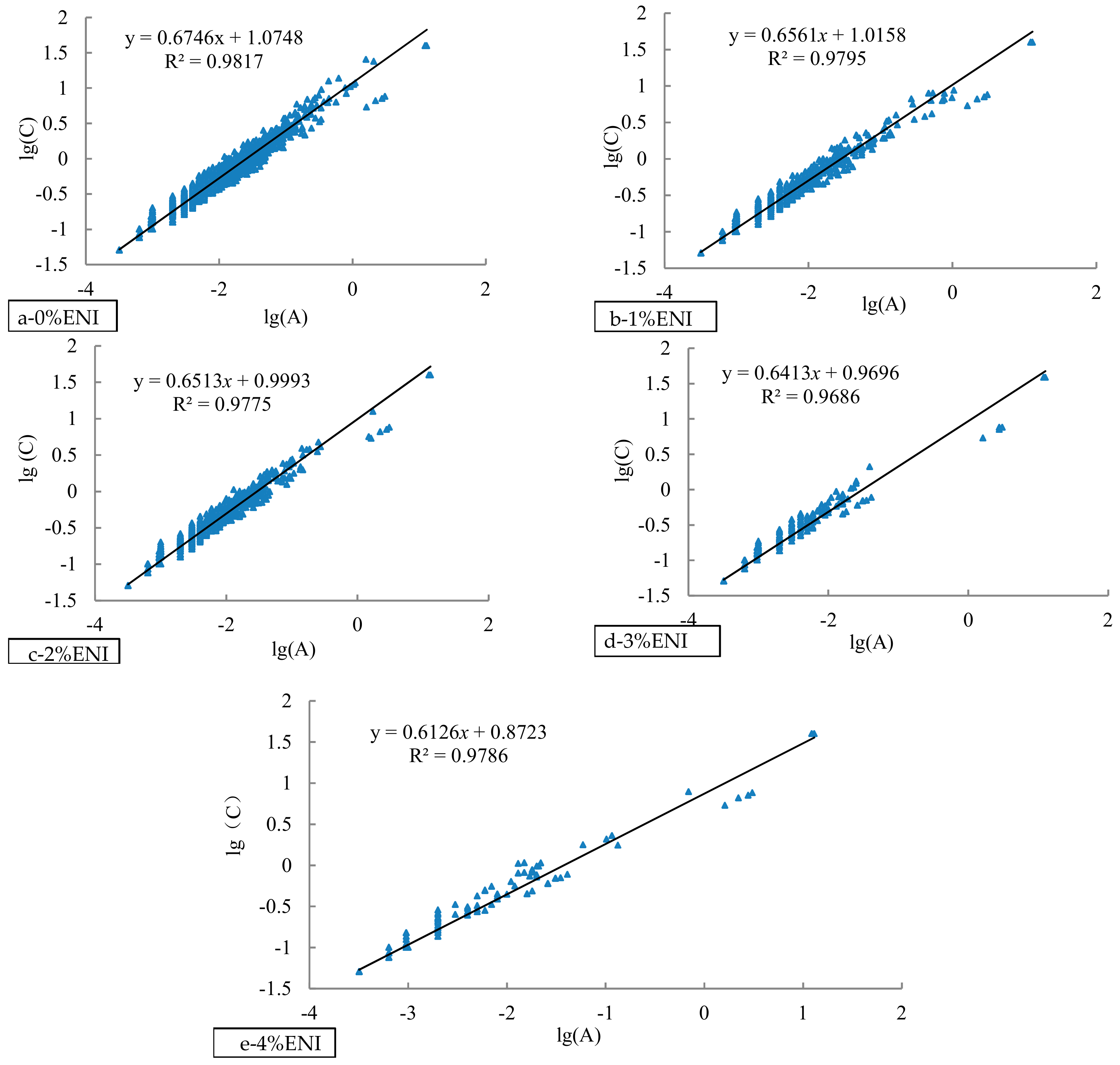
In this paper, the experimental results of the microscopic pore characteristics in the samples are fitted by Equation (1) (shown in Figure 5). In the figure, the logarithm of area was set as the abscissa and the logarithm of the perimeter is set as the ordinate. If the experimental results were linearly correlated, the fitting results were good. Then, the value of fractal dimension is equal to twice the line slope.
It can be observed from Figure 5 that lg (A) and lg (C) were positively correlated, and the linear correlation between parameters is good. The judgment coefficient R2 belongs to 0.9686~0.9817, so the fitting goodness is very high. Therefore, the fractal dimension can be derived from the calculation of the fitted curve. The fractal dimension of the sample could be obtained in Table 3.
Fractal dimension can represent the spatial geometric complexity of pore shape. The larger the fractal dimension, the higher the spatial geometric complexity of the pore shape, the rougher the sample surface, and the worse the mechanical properties of the sample [40]. There is a certain correlation between UCS and pores. In the same rock sample, the more the rock pores, the smaller the UCS. The effect of the pores on the uniaxial compressive strength is greater than the Young’s modulus [41,42]. According to Table 3, when the ENI concentration was 0%, the fractal dimension was 1.35. While the concentration increases by 1%, the fractal dimension decreases to 1.31, which is 3% lower than the former one. ENI can inhibit shale pore development. However, the inhibitory effect was not significant when the ENI concentration was 1%. With the increase of ENI concentration, the fractal dimension decreases gradually. It indicates that drilling fluid inhibition increases gradually. Meanwhile, other parameters like pore extension and rock damage are inhibited, and the sample surface becomes smooth. The most important is that the shale sample strength increases. This fractal dimension is opposite to the trend of UCS, indicating that ENI enhances shale strength by inhibiting pore growth. It also shows that the shale strength is negatively correlated with the pores. Under the influence of 4% of ENI, the fractal dimension reached the minimum value of 1.23, which is 9.19% lower than 0% of ENI. It indicates that 4% of ENI had the strongest inhibitory effect on shale. When the ENI was in contact with the shale, it changed the hydrophilicity of the shale surface and made the shale pores smaller. At the same time, ENI made the shale particles dense and the sample strength will increase. As the increases of ENI concentration, the rock integrity was better. More importantly, the mechanical properties of the shale were improved.
3.2.2. Ratio of Stability Coefficients
The ratio of stability coefficients Kn can be obtained by Equation 4 at different concentrations of ENI. The statistical range was calculated according to the 50 mm diameter core samples. The Kn values (n = 1, 2, 3,4) are shown in Table 4.
Kn represents the difference in shale strength between ENI and without ENI. Under the action of water, the shale strength decreases. ENI can change the hydrophilicity of shale, reduce the impact of water on shale and increase sample’s strength. The larger Kn, the different concentrations’ ENI affection on shale strength is greater. It also means that the shale strength is higher under the action of ENI. According to Table 4, for the four different ENI concentrations, the ratio of stability coefficients was less than 0.6, much less than 1. The stability of the sample under ENI was higher than that of the sample without ENI, and the shale pore extension was inhibited. It indicates that ENI can not only improve the stability of the borehole wall, but also enhance the strength of shale. The ratio of stability coefficient was negatively correlated with ENI concentration. It indicates that the higher the ENI concentration, the better the sample integrity. Meanwhile, the sample strength was also higher and the pore walls are more stable. K4 was only 0.428, which was 28% smaller than K1, and K1 was 0.598. ENI of 4% had a better effect on shale strength than 1% ENI. These results indicate that the shale sample surface is further inhibited and its strength increases as ENI concentration increases. In addition, the difference between K3 and K2 was the largest, which indicates that the shale strength changes most when the ENI concentration was 3%. The reason for this change cannot be explained detail based on available data, which may require more trials to verify.
By comparison, it was found that the results of the uniaxial compression test and the pore microscopic characteristics test were consistent. As the concentration of ENI increases, the pores decrease and the surface of the shale becomes smooth. It shows that ENI enhances shale strength and improves pore wall stability by inhibiting shale pore development. It was further verified that ENI could improve the mechanical strength of shale and effectively improve the stability of the borehole.
4. Conclusions
(1) The UCS and Young’s modulus are positively correlated with the ENI concentration. As the ENI concentration increases, shale hydration expansion is inhibited and the overall strength of the shale increases. Due to the inhibitory effect on clay minerals with ENI, the effect of ENI on Young’s modulus is greater than that of UCS. As the concentration of ENI increases, the UCS and Young’s modulus increase rates of shale decrease, but no apex appears. One issue is to determine the appropriate concentration of ENI in future studies.
(2) When the ENI is in contact with the shale, it changes the hydrophilicity of the shale surface and makes the shale pores smaller. At the same time, ENI will make the shale particles become dense and the sample strength will increase. With the increase of ENI concentration, the fractal dimension decreases gradually. It indicates that drilling fluid inhibition increases gradually. Meanwhile, other parameters like pore extension and rock damage are inhibited, and the sample surface becomes smooth. What matters most is that the shale sample strength increases. This fractal dimension is opposite to the trend of UCS, indicating that ENI enhances shale strength by inhibiting pore growth.
(3) The ratio of stability coefficient is an intuitive expression which can reflect pore, strength and stability properties. The ratio of the stability coefficient is inversely related to the ENI concentration. This means that the higher the ENI concentration, the better the sample integrity. At the same time, the sample strength is also higher and the borehole is more stable. The stability of the sample under ENI is higher than the sample without ENI, and the shale pore extension is inhibited. It indicates that ENI can not only improve the stability of the borehole wall, but also enhance the strength of shale.
Author Contributions
Conceptualization, H.P., J.Z., and M.T.; Methodology, H.P., H.C. and X.Z.; Software, M.T. and J.Z.; Validation, B.Z., W.L., J.Z. and M.H.; Writing-Original Draft Preparation, H.P., J.Z., X.Z. and H.C.; Writing-Review & Editing, H.P., J.Z., X.Z., B.Z., W.L., and H.C.
Funding
This study was supported by the National Natural Science Foundation of China (No. 41602372), open fund of the State Key Laboratory of Oil and Gas Reservoir Geology and Exploitation (Southwest Petroleum University, No. PLN201609 and No. PLN201607, fund of Ministry of Land and Resources Key Laboratory of Drilling Technology in Complex Conditions (No. DET201612), and the Fundamental Research Funds for the Central Universities of Central South University (No. 2018zzts690 and No. 2019zzts636). All of the authors would like to direct their thanks to the professors and students in the Key Laboratory of Metallogenic Prediction of Nonferrous Metals and Geological Environment Monitoring (Central South University), Ministry of Education.
Conflicts of Interest
The authors declare no conflict of interest.
References
- Tonglou, G. Key geological issues and main controls on accumulation and enrichment of Chinese shale gas. Pet. Explor. Dev. 2016, 43, 349–359. [Google Scholar]
- Wan, Y.; Tang, S.; Pan, Z. Evaluation of the shale gas potential of the lower Silurian Longmaxi Formation in northwest Hunan Province, China. Mar. Pet. Geol. 2017, 79, 159–175. [Google Scholar] [CrossRef]
- Ge, H.-K.; Yang, L.; Shen, Y.-H.; Ren, K.; Meng, F.-B.; Ji, W.-M.; Wu, S. Experimental investigation of shale imbibition capacity and the factors influencing loss of hydraulic fracturing fluids. Pet. Sci. 2015, 12, 636–650. [Google Scholar] [CrossRef] [Green Version]
- Cao, H.; Wang, T.; Bao, T.; Sun, P.; Zhang, Z.; Wu, J. Effective exploitation potential of shale gas from lower cambrian niutitang formation, Northwestern Hunan, China. Energies 2018, 11, 3373. [Google Scholar] [CrossRef]
- Chen, J.; Cao, H.; Sun, P. Fracability evaluation of shale in Niutitang formation in northwestern Hunan. Earth Sci. Front. 2017, 24, 390–398. (in Chinese). [Google Scholar]
- Kumar, S.; Jain, R.; Chaudhary, P.; Mahto, V. Development of inhibitive water based drilling fluid system with synthesized graft copolymer for reactive Indian shale formation. In SPE Oil & Gas India Conf.Exhibit; Society of Petroleum Engineers: Dubai, UAE, 2017. [Google Scholar]
- Liu, X.; Zeng, W.; Liang, L.; Lei, M. Wellbore stability analysis for horizontal wells in shale formations. J. Nat. Gas Sci. Eng. 2016, 31, 1–8. [Google Scholar] [CrossRef]
- Abbas, A.K.; Flori, R.E.; Al-Anssari, A.; Alsaba, M. Laboratory analysis to assess shale stability for the Zubair Formation, Southern Iraq. J. Nat. Gas Sci. Eng. 2018, 56, 315–323. [Google Scholar] [CrossRef]
- Yu, M.; Chenevert, M.E.; Sharma, M.M. Chemical–mechanical wellbore instability model for shales: Accounting for solute diffusion. J. Pet. Sci. Eng. 2003, 38, 131–143. [Google Scholar] [CrossRef]
- Mahto, V.; Sharma, V.P. Rheological study of a water based oil well drilling fluid. J. Pet. Sci. Eng. 2004, 45, 123–128. [Google Scholar] [CrossRef]
- Xuan, Y.; Jiang, G.; Li, Y.; Geng, H.; Wang, J. A biomimetic drilling fluid for wellbore strengthening. Pet. Explor. Dev. 2013, 40, 531–536. [Google Scholar] [CrossRef]
- Ferreira, C.C.; Teixeira, G.T.; Lachter, E.R.; Nascimento, R.S.V. Partially hydrophobized hyperbranched polyglycerols as non–ionic reactive shale inhibitors for water–based drilling fluids. Appl. Clay Sci. 2016, 132, 122–132. [Google Scholar] [CrossRef]
- Xu, J.-G.; Qiu, Z.; Zhao, X.; Huang, W. Hydrophobic modified polymer based silica nanocomposite for improving shale stability in water–based drilling fluids. J. Pet. Sci. Eng. 2017, 153, 325–330. [Google Scholar]
- Koteeswaran, S.; Pashin, J.C.; Ramsey, J.D.; Clark, P.E. Quantitative characterization of polyacrylamide-shale interaction under various saline conditions. Pet. Sci. 2017, 14, 586–596. [Google Scholar] [CrossRef]
- Zhang, J.; Li, L.; Wang, S.; Wang, J.; Yang, H.; Zhao, Z.; Zhu, J.; Zhang, Z. Novel micro and nano particle-based drilling fluids: Pioneering approach to overcome the borehole instability problem in shale formations. In SPE Asia Pacific Unconventional Resources Conference and Exhibition; Society of Petroleum Engineers: Dubai, UAE, 2015. [Google Scholar]
- Zulfiqar, S.; Sarwar, M.I.; Rasheed, N.; Yavuz, C.T. Influence of interlayer functionalization of kaolinite on property profile of copolymer nanocomposites. Appl. Clay Sci. 2015, 112, 25–31. [Google Scholar] [CrossRef]
- Vryzas, Z.; Kelessidis, V.C. Nano-based drilling fluids: A review. Energies 2017, 10, 540. [Google Scholar] [CrossRef]
- Zhong, H.; Qiu, Z.; Huang, W.; Sun, D.; Zhang, D.; Cao, J. Synergistic stabilization of shale by a mixture of polyamidoamine dendrimers modified bentonite with various generations in water-based drilling fluid. Appl. Clay Sci. 2015, 114, 359–369. [Google Scholar] [CrossRef]
- Moslemizadeh, A.; Aghdam, S.K.-Y.; Shahbazi, K.; Zendehboudi, S. A triterpenoid saponin as an environmental friendly and biodegradable clay swelling inhibitor. J. Mol. Liq. 2017, 247, 269–280. [Google Scholar] [CrossRef]
- Jain, R.; Mahto, V. Formulation of a water based drilling fluid system with synthesized graft copolymer for troublesome shale formations. J. Nat. Gas Sci. Eng. 2017, 38, 171–181. [Google Scholar] [CrossRef]
- Katz, L.E.; Rauch, A.F.; Liljestrand, H.M.; Harmon, J.S.; Shaw, K.S.; Albers, H. Mechanisms of soil stabilization with liquid ionic stabilizer. Transp. Res. Record 2001, 1757, 50–57. [Google Scholar] [CrossRef]
- Berry, S.L.; Boles, J.L.; Brannon, H.D.; Beall, B.B. Performance evaluation of ionic liquids as a clay stabilizer and shale inhibitor. In SPE International Symposium and Exhibition on Formation Damage Control; Society of Petroleum Engineers: Dubai, UAE, 2008. [Google Scholar]
- Petry, T.M.; Das, B. Evaluation of chemical modifiers and stabilizers for chemically active soils—Clays. Transp. Res. Rec. J. Transp. Res. Board 2001, 1757, 43–49. [Google Scholar] [CrossRef]
- Blanck, G.; Cuisinier, O.; Masrouri, F. Soil treatment with organic non–traditional additives for the improvement of earthworks. Acta Geotech. 2014, 9, 1111–1122. [Google Scholar] [CrossRef]
- Latifi, N.; Rashid, A.S.A.; Siddiqua, S.; Horpibulsuk, S. Micro-structural analysis of strength development in low- and high swelling clays stabilized with magnesium chloride solution—A green soil stabilizer. Appl. Clay Sci. 2015, 118, 195–206. [Google Scholar] [CrossRef]
- Wang, F.; Xiang, W.; Corely, T.; Yeh, T.-C.J.; Yuan, Y. The influences of freeze-thaw cycles on the shear strength of expansives treated with ionic soil stabilizer. Soil Mech. Found. Eng. 2018, 55, 195–200. [Google Scholar] [CrossRef]
- Yang, L.; Jiang, G.; Shi, Y.; Yang, X. Application of ionic liquid and polymeric ionic liquid as shale hydration inhibitors. Energ. Fuels 2017, 31, 4308–4317. [Google Scholar] [CrossRef]
- Sameni, A.; Pourafshary, P.; Ghanbarzadeh, M.; Ayatollahi, S. Effect of nanoparticles on clay swelling and migration. Egypt. J. Pet. 2015, 24, 429–437. [Google Scholar] [CrossRef] [Green Version]
- Luo, Z.; Wang, L.; Yu, P.; Chen, Z. Experimental study on the application of an ionic liquid as a shale inhibitor and inhibitive mechanism. Appl. Clay Sci. 2017, 150, 267–274. [Google Scholar] [CrossRef]
- Mohammed, A.; Tariq, A.; Elhajj, H.; Walter, S.; Ibrahim, A. Unconventional Clay Control Alternative to Inorganic Compounds that Can Prevent Swelling and Reduce Friction in Underbalanced Drilling. In SPE Middle East Oil and Gas Show and Conference; Society of Petroleum Engineers: Dubai, UAE, 2019. [Google Scholar]
- Chenevert, M.E. Shale alteration by water adsorption. J. Pet. Tech. 1970, 22, 1–141. [Google Scholar] [CrossRef]
- Tandanand, S. Moisture adsorption rate and strength degradation of Illinois shales. In The 26th US Symposium on Rock Mechanics (USRMS); American Rock Mechanics Association: Alexandria, VA, USA, 1985. [Google Scholar]
- Gao, H.; Li, H.A. Pore structure characterization, permeability evaluation and enhanced gas recovery techniques of tight gas sandstones. J. Nat. Gas Sci. Eng. 2016, 28, 536–547. [Google Scholar] [CrossRef]
- Sun, P.; Zhao, B.; Cao, H.; Wang, J.; Mo, D.; Zhang, S. Lab study on the effect of cation exchange capacity on slurry performance in slurry shields. Adv. Civ. Eng. 2018. [Google Scholar] [CrossRef]
- Sun, P.; Tian, M.; Cao, H.; Niu, L.; Zhang, S. Study on the mechanism of ENI action on preventing drilling fluid overflowing in HDD. Tunn. Undergr. Sp. Tech. 2018, 77, 94–102. [Google Scholar] [CrossRef]
- Kawamoto, T.; Ichikawa, Y.; Kyoya, T. Deformation and fracturing behaviour of discontinuous rock mass and damage mechanics theory. Int. J. Numer. Anal. Methods Géoméch. 1988, 12, 1–30. [Google Scholar] [CrossRef]
- Lu, Y.; Li, X.; Chan, A. Damage constitutive model of single flaw sandstone under freeze-thaw and load. Cold Reg. Sci. Tech. 2019, 159, 20–28. [Google Scholar] [CrossRef]
- Kim, J.-S.; Lee, K.-S.; Cho, W.-J.; Choi, H.-J.; Cho, G.-C. A comparative evaluation of stress–strain and acoustic emission methods for quantitative damage assessments of brittle rock. Rock Mech. Rock Eng. 2015, 48, 495–508. [Google Scholar] [CrossRef]
- Zhang, Z.; Zhang, R.; Xie, H.; Liu, J.; Were, P. Differences in the acoustic emission characteristics of rock salt compared with granite and marble during the damage evolution process. Environ. Earth Sci. 2015, 73, 6987–6999. [Google Scholar] [CrossRef]
- Gu, X.B.; Wu, Q.H. The application of nonordinary, state-based peridynamic theory on the damage process of the rock-like materials. Math. Probl. Eng. 2016, 2016, 1–9. [Google Scholar] [CrossRef]
- Jamshidi, A.; Zamanian, H.; Sahamieh, R.Z. The effect of density and porosity on the correlation between uniaxial compressive strength and P-wave velocity. Rock Mech. Rock Eng. 2018, 51, 1279–1286. [Google Scholar] [CrossRef]
- Rajabzadeh, M.A.; Moosavinasab, Z.; Rakhshandehroo, G. Effects of rock classes and porosity on the relation between uniaxial compressive strength and some rock properties for carbonate rocks. Rock Mech. Rock Eng. 2012, 45, 113–122. [Google Scholar] [CrossRef]
Figure 1.
Small modified portable drilling rig in the jobsite.

Figure 2.
Uniaxial compression stress–strain curve of carbonaceous shale.

Figure 3.
Shale uniaxial compression test results.

Figure 4.
Microstructural diagram of shale pores. (a) 1% ENI; (b) 1% ENI; (c) 2% ENI; (d) 3% ENI; (e) 4% ENI.
Figure 4.
Microstructural diagram of shale pores. (a) 1% ENI; (b) 1% ENI; (c) 2% ENI; (d) 3% ENI; (e) 4% ENI.

Figure 5.
Shale sample fractal curve fitting result chart. (a) 1% ENI; (b) 1% ENI; (c) 2% ENI; (d) 3% ENI; (e) 4% ENI.
Figure 5.
Shale sample fractal curve fitting result chart. (a) 1% ENI; (b) 1% ENI; (c) 2% ENI; (d) 3% ENI; (e) 4% ENI.


Table 1.
X-ray diffraction (XRD) analysis results of mineral composition of carbonaceous shale.
| Rock | Mass Percentage | |||||
|---|---|---|---|---|---|---|
| Quartz | Mica | Feldspar | Smectite | Anatase | Amorphous Substance | |
| Carbonaceous shale | 16.57 | 13.64 | 10.82 | 25.58 | 5.26 | 28.13 |
Table 2.
Statistical table of information on shale pore characteristics.
| Pore Area/μm2 | Pore Perimeter/μm | |||||||||
|---|---|---|---|---|---|---|---|---|---|---|
| 0% ENI | 1% ENI | 2% ENI | 3% ENI | 4% ENI | 0% ENI | 1% ENI | 2% ENI | 3% ENI | 4% ENI | |
| Summary | 84.716 | 50.656 | 47.454 | 38.875 | 36.278 | 1955.551 | 589.734 | 656.714 | 204.437 | 166.272 |
| Average | 0.589 | 0.418 | 0.418 | 0.368 | 0.359 | 5.477 | 2.657 | 2.433 | 1.573 | 1.543 |
Table 3.
Fractal dimension with different enhanced normality ionic (ENI) concentrations.
| Concentration | Fractal Dimension |
|---|---|
| 0% ENI | 1.35 |
| 1% ENI | 1.31 |
| 2% ENI | 1.30 |
| 3% ENI | 1.28 |
| 4% ENI | 1.23 |
Table 4.
Ratio of shale stability.
| Number | K1 | K2 | K3 | K4 |
|---|---|---|---|---|
| Ratio of Shale Stability | 0.598 | 0.560 | 0.459 | 0.428 |
© 2019 by the authors. Licensee MDPI, Basel, Switzerland. This article is an open access article distributed under the terms and conditions of the Creative Commons Attribution (CC BY) license (http://creativecommons.org/licenses/by/4.0/).
Share and Cite
MDPI and ACS Style
Sun, P.; Zhu, J.; Zhao, B.; Zhang, X.; Cao, H.; Tian, M.; Han, M.; Liu, W. Study on the Mechanism of Ionic Stabilizers on Shale Gas Reservoir Mechanics in Northwestern Hunan. Energies 2019, 12, 2453. https://doi.org/10.3390/en12122453
AMA Style
Sun P, Zhu J, Zhao B, Zhang X, Cao H, Tian M, Han M, Liu W. Study on the Mechanism of Ionic Stabilizers on Shale Gas Reservoir Mechanics in Northwestern Hunan. Energies. 2019; 12(12):2453. https://doi.org/10.3390/en12122453
Chicago/Turabian StyleSun, Pinghe, Junyi Zhu, Binkui Zhao, Xinxin Zhang, Han Cao, Mingjin Tian, Meng Han, and Weisheng Liu. 2019. "Study on the Mechanism of Ionic Stabilizers on Shale Gas Reservoir Mechanics in Northwestern Hunan" Energies 12, no. 12: 2453. https://doi.org/10.3390/en12122453
Note that from the first issue of 2016, this journal uses article numbers instead of page numbers. See further details here.