Article

Power Control and Fault Ride-Through Capability Analysis of Cascaded Star-Connected SVG under Asymmetrical Voltage Conditions

National Electric Power Conversion and Control Engineering Technology Research Center, Hunan University, Changsha 410082, China
*
Authors to whom correspondence should be addressed.
Energies 2019, 12(12), 2361; https://doi.org/10.3390/en12122361
Submission received: 8 May 2019 / Revised: 12 June 2019 / Accepted: 14 June 2019 / Published: 19 June 2019
(This article belongs to the Section F: Electrical Engineering)

Abstract

:
The cascaded H-bridge static var generator (SVG) has been employed to provide reactive power and regulate grid voltages for many years because of its good modularity, easy scalability, and improved harmonic performance. A novel cluster-balancing power control method combining negative-sequence currents and zero-sequence voltage is proposed to redistribute the unbalanced active powers and eliminate the power oscillation under asymmetrical conditions. Simultaneously, the dynamic performance of the SVG power balance control can be improved under asymmetrical conditions with the zero-sequence voltage expression derived in this paper. On the basis of the proposed method, the fault ride through capability of star-connected SVG under asymmetrical conditions is compared among active power oscillation elimination (APOE), reactive power oscillation elimination (RPOE), and balanced positive sequence current (BPSC) injection references calculation strategies from the perspective of the zero-sequence voltage, maximum phase voltage, and maximum phase current. The method provides the theoretical reference for power control under asymmetric conditions and the analysis results show that under asymmetrical conditions, the current of BPSC is minimal and symmetrical, while the RPOE has the least voltage and no zero- sequence voltage needs to be injected. Finally, the results of simulation and experiment have been given to verify the theoretical studies.

1. Introduction

With the development of renewable energy sources and distributed generations, more and more photovoltaic and wind power plants are connected to the power grid [1,2,3]. The use of renewable energy can reduce environmental pollution and system losses, but it also brings a series of power quality problems, such as voltage drop and flicker, current harmonic pollution, and three-phase unbalance, which threaten the safety and economic operation of the power system [4,5,6]. To solve these problems, reactive power and grid voltage support becoming more crucial [7,8]. The static var generator (SVG) is an effective solution to supply reactive power for power systems to control the power factor and regulate the grid voltage. The SVG based on a cascaded multi-level structure is one of the most effective power quality solutions in high-voltage and high-capacity applications, due to its advantages of modular structure, fast reactive power adjustment, transformer-less, and desirable output performance [9,10,11,12,13].
Although cascaded multilevel structure has the advantages of high voltage capacity and low switching frequency [14,15], the cascaded SVG has no common DC bus and the DC-link capacitor of each H-bridge module is separate, the power balance of each H-bridge module and each phase becomes a critical issue, especially under asymmetrical voltage conditions. Generally, the three-phase cascaded SVG has two typical structures: the cascade H-bridge star-connection and delta-connection [16]. The star-connection SVG are rated at phase voltage of the connected grid, it has fewer modules compared to the delta-connected structure, and its virtual neutral point could be used to inject zero-sequence voltage to maintain the inter-phase power balance. The study of this paper will focus on the star-connected SVG.
Many researchers have discussed and explored the control and operation methods of star-connected cascaded SVG. Power balancing is one of the most critical issues of cascaded SVG. Generally, a hierarchical balancing control strategy is the main approach to deal with this issue, the hierarchical strategy consists of three cascaded loops, namely, overall balancing control, cluster-balancing control and sub-module balancing control. Among the three cascaded voltage control loops, the cluster-balancing control is most complicated and crucial considering that the active power of each phase is not only related to the difference of sub-module but also the unsatisfactory states, such as asymmetrical grid voltages or the unbalance of phase currents. Several investigations have been carried out for the cluster-balancing control methods. Generally, those methods can be arranged into two categories: the zero-sequence voltage injection and the negative-sequence current injection. Zero-sequence voltage injection was introduced to balance power by the virtual neutral point in [13,17,18,19,20]. In Reference [18], the zero-sequence voltage injection technique was used to achieve the redistribution of the uneven active power when the SVG provided negative sequence currents to compensate for the unbalanced currents caused by an unbalanced load, while the positive sequence current and asymmetrical grid voltages were not discussed, which could have an influence on the cluster voltage balancing control. To improve the voltage balancing control performance, a general solution for the zero-sequence voltage considering the negative-sequence voltage was provided in References [13,19,20]. In Reference [17], a simplified zero-sequence voltage calculation method is proposed sine the calculation, which derived from the equilibrium of the active power for each phase cluster, is quite complicated in the form of trigonometric function. Further, the ability of cascaded star-connected SVG to exchange negative-sequence current with grid was investigated based on the zero-sequence voltage expression in Reference [21].
In References [22,23], negative-sequence current injection method was proposed to balance the inter-phase power. Since both the negative sequence current and voltage are used to transfer the unbalanced active power of three phases, this method has better power regulation capability. However, the negative sequence current would affect the power quality and grid voltage. The average power balancing control was achieved by introducing the negative-sequence current in Reference [24], and it showed that the star-connected SVG had a larger operation area with negative-sequence current injection under the grid fault condition.
However, little attention has been paid to the reactive power control of star-connected SVG under asymmetrical voltage conditions. Considering the asymmetrical conditions, SVG has several power control strategies with different negative-sequence current references, include active power oscillation elimination (APOE), reactive power oscillation elimination (RPOE) and balanced positive sequence current (BPSC). Different negative-sequence current references need different zero-sequence voltages, then, the reactive power support capacity of SVG varies with different power control strategies. Therefore, it is essential necessary to investigate the reactive power control method and reactive power support capability of cascaded star-connected SVG under asymmetrical voltage conditions. While, the current research has not yet investigated the fault ride through capability of star-connected SVG under asymmetrical conditions from the perspective of the zero-sequence voltage, the maximum phase voltage and the maximum phase current.
In this paper, the reactive power control strategies of the star-connected SVG under asymmetrical grid voltage conditions are investigated. Negative-sequence currents and zero-sequence voltage are combined to keep the inter-phase power balancing and eliminate the active power or reactive power oscillation. On the basis of this, the fault ride-through capability of a star-connected SVG under asymmetrical conditions is investigated, which could provide the theoretical reference for power control under asymmetric conditions. This paper is organized as follows: The system configuration is introduced in Section 2. The inter-phase voltage balancing control method is proposed by injecting zero-sequence voltage in the dq frame in Section 3. The fault ride-through capability of the star-connected SVG under asymmetrical conditions in three strategies is compared in Section 4. Simulation and experiment results are offered to verify the proposed method in Section 5. Finally, conclusions are drawn in Section 6.

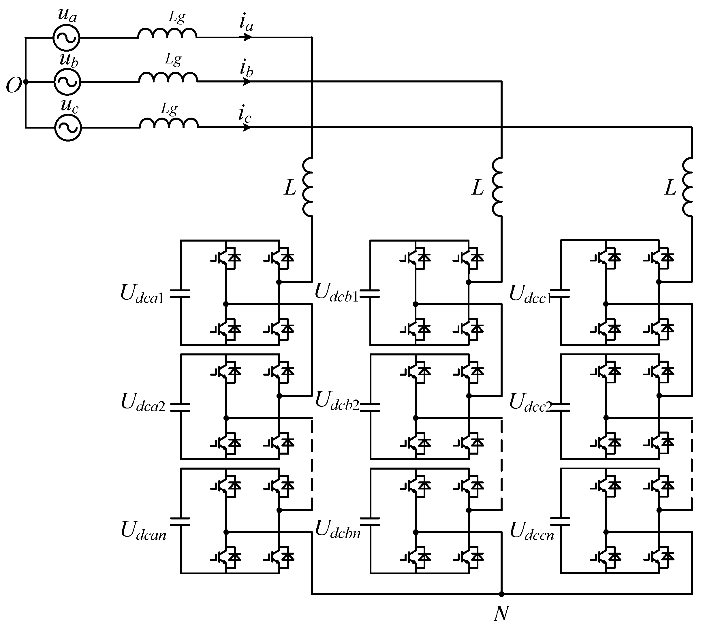
2. System Configuration

The typical star-connected SVG topology, as shown in Figure 1, is composed of a cascade of n sub-module units. uaO, ubO, ucO and ia, ib, ic are phase voltage and phase current of grid side, Lg is the grid inductance, L is the AC inductor filter. N is the neutral point of star-connected SVG, uNO is the zero-sequence voltage, and uaN, ubN, and ucN are the output voltages.
According to the Kirchhoff’s current law:
{ ( L + L g ) d i a d t = u a u a N ( L + L g ) d i b d t = u b u b N ( L + L g ) d i c d t = u c u c N
Assuming that the DC capacitor voltage of three phases are Udca, Udcb, and Udcc, the expressions of the three-phase energies are obtained according to the energy equations:
{ d d t ( 1 2 C N U d c a 2 ) = P a = u a N i a d d t ( 1 2 C N U d c b 2 ) = P b = u b N i b d d t ( 1 2 C N U d c c 2 ) = P c = u c N i c
where Pa, Pb, and Pc are the powers of three phase. the instantaneous grid side voltages under asymmetrical voltage conditions can be defined as:
[ u a u b u c ] = [ U + sin ( ω t + φ + ) + U sin ( ω t + φ ) U + sin ( ω t 2 3 π + φ + ) + U sin ( ω t + 2 3 π + φ ) U + sin ( ω t + 2 3 π + φ + ) + U sin ( ω t 2 3 π + φ ) ]
where U+ and U are the amplitude of positive sequence voltage and negative sequence voltage, φ+ and φ are phase angle of positive sequence voltage and negative sequence voltage. The positive and negative sequence voltages in the dq frame can be expressed as:
{ u + = u d + + j u q + u = u d + j u q
where udq+ and udq are the dq components of positive-sequence voltage and negative-sequence voltage respectively. Considering the unbalanced phase currents, the positive and negative-sequence currents of phase currents can be expressed as:
{ i + = i d + + j i q + i = i d + j i q
where idq+ and idq are the dq components of positive-sequence currents and negative-sequence currents respectively. Assuming uq+=0, based on Equations (3) and (4), phase voltage phasors can be expressed as:
{ u a = ( u d + + u d ) + j ( u q ) u b = ( 1 2 u d + 1 2 u d 3 2 u q ) + j ( 3 2 u d + + 3 2 u d 1 2 u q ) u c = ( 1 2 u d + 1 2 u d + 3 2 u q ) + j ( + 3 2 u d + 3 2 u d 1 2 u q )
Similarly, phase currents phasors can be expressed as:
{ i a = ( i d + + i d ) + j ( i q + + i q ) i b = ( 1 2 i d + 1 2 i d + 3 2 i q + 3 2 i q ) + j ( 3 2 i d + + 3 2 i d 1 2 i q + 1 2 i q ) i c = ( 1 2 i d + 1 2 i d 3 2 i q + + 3 2 i q ) + j ( 3 2 i d + 3 2 i d 1 2 i q + 1 2 i q )
Neglecting the active power loss caused by the parasitic resistance of inductor, the active power in the abc frame can be obtained as follows:
{ p a = 1 2 ( u d + + u d ) i d + + 1 2 ( u d + + u d ) i d + 1 2 u q i q + + 1 2 u q i q p b = ( 1 2 u d + 1 4 u d + 3 4 u q ) i d + + ( 1 4 u d + + 1 2 u d ) i d + ( 3 4 u d 1 4 u q ) i q + + ( 3 4 u d + + 1 2 u q ) i q p c = ( 1 2 u d + 1 4 u d 3 4 u q ) i d + + ( 1 4 u d + + 1 2 u d ) i d + ( 3 4 u d 1 4 u q ) i q + + ( 3 4 u d + + 1 2 u q ) i q
Applying the αβ transformation into Equation (8):
[ p α p β p 0 ] = 2 3 [ 1 1 2 1 2 0 3 2 3 2 1 2 1 2 1 2 ] [ p a p b p c ]

3. Power Balance Control under Asymmetrical Voltage Conditions

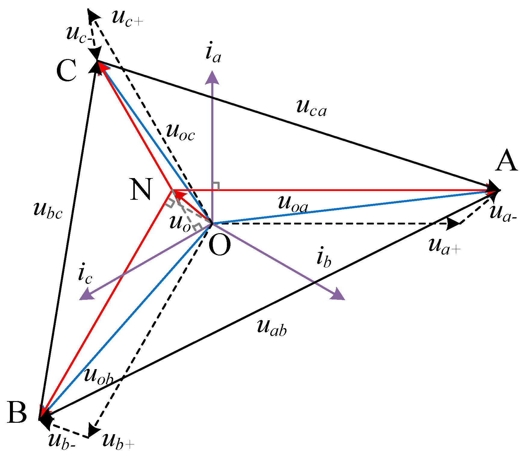
3.1. Zero-Sequence Voltage Derivation

Since the DC bus capacitor of cascaded star-connected SVG is independent in each phase, from Equation (8), it can be seen that the active power generated by the asymmetric voltages and currents is unbalanced, which will cause unbalanced capacitor voltages. Zero-sequence voltage injection can redistribute the active powers by adjusting the position of the virtual neutral point. Figure 2 shows phasor diagram of star-connected SVG. Phase voltage and current phasors contain positive and negative-sequence components. Without zero-sequence voltage, the N and O are coincident, while the voltage phasors UaO, UbO, and UcO are not perpendicular to the current phasors Ia, Ib, and Ic in three phases. Under this condition, the active power of three phases caused by the phase voltages and currents are not zero and unbalanced. Zero-sequence voltage can be employed to redistribute the unbalanced active power. After the zero-sequence voltage uNO is injected, the voltage phasors UaN, UbN, and UcN become perpendicular to the current phasors Ia, Ib, and Ic, as shown in Figure 2 and the active powers are rebalanced.
In order to simplify the calculation, power analysis is performed in the αβ coordinate system. According to Equations (9), after zero-sequence voltage is injected, the active power in the αβ frame can be expressed as:
[ p f α p f β ] = 2 3 [ 1 1 2 1 2 0 3 2 3 2 ] [ p a + p a 0 p b + p b 0 p c + p c 0 ] = [ p α p β ] + [ p α 0 p β 0 ]
where p and p are three phase active power components in the α-axis and β-axis, pα0 and pβ0 are the active power components generated by the zero-sequence voltage in the α-axis and β-axis:
[ p α 0 p β 0 ] = [ p f α p f β ] [ p α p β ]
The inter-phase power balance control based on zero-sequence voltage injection is illustrated in Figure 3. The unbalance of DC voltages in the αβ coordinate system is used as a feedback signal to obtain the αβ axis power adjustment through the proportional-integral PI controller. Additionally, the active power components produced by the phase voltages and currents are introduced as the power feedforward to improve the dynamic performance of power balance control.
Setting zero-sequence voltage phasor as:
u N O = x + j y
Combining Equations (7) and (12), pα0 and pβ0 can be obtained as:
{ p a 0 = 1 2 ( i d + + i d ) x + 1 2 ( i q + + i q ) y p b 0 = ( 1 4 i d + 1 4 i d + 3 4 i q + 3 4 i q ) x + ( 3 4 i d + + 3 4 i d 1 4 i q + 1 4 i q ) y p c 0 = ( 1 4 i d + 1 4 i d 3 4 i q + + 3 4 i q ) x + ( 3 4 i d + 3 4 i d 1 4 i q + 1 4 i q ) y
Applying the αβ transformation to Equation (13):
[ p α 0 p β 0 ] = 2 3 [ 1 1 2 1 2 0 3 2 3 2 ] [ p a 0 p b 0 p c 0 ] = 3 8 [ i d + + i d i q + + i q i q + i q i d + + i d ] [ x y ]
Combining Equations (11) and (14), the zero-sequence voltage can be derived as:
[ x y ] = 1 i d + i d + i d i d + i q + i q + i q i q [ i d + + i d i q + i q i q + + i q i d + + i d ] ( [ i d i d + i q + i q i q + i d + ] [ u d + u d u q ] 8 3 [ P f α P f β ] )

3.2. Negative-Sequence Current References

In this part, the negative-sequence current references are calculated, three generalized current references calculation strategies: APOE, RPOE, and BPSC are taken into account. According to instantaneous reactive power theory, the instantaneous active power and reactive power provided by SVG under asymmetrical conditions can be expressed as:
{ p = P 0 + P c 2 cos ( 2 ω t ) + P s 2 sin ( 2 ω t ) q = Q 0 + Q c 2 cos ( 2 ω t ) + Q s 2 sin ( 2 ω t )
According to Equations (6) and (7):
{ P 0 = 3 2 ( u d + i d + + u d i d + u q + i q + + u q i q ) P c 2 = 3 2 ( u q i d + + u q + i d + u d i q + + u d + i q ) P s 2 = 3 2 ( u d i d + + u d + i d u q i q + u q + i q ) Q 0 = 3 2 ( u q + i d + + u q i d u d + i q + u d i q ) Q c 2 = 3 2 ( u d i d + u d + i d u q i q + + u q + i q ) Q s 2 = 3 2 ( u q i d + + u q + i d u d i q + + u d + i q )
where P0 is the average values of instantaneous active, it is always used to compensate the total power losses, and it is quite small comparing to the reactive power. Q0 is the average values of instantaneous reactive power, it is always controlled to the reactive power reference. Pc2, Ps2, Qc2, and Qs2 are the magnitudes of the oscillating terms. Since Equation (17) has four degrees of freedom, then, the resting ones can be utilized to eliminate the active power or the reactive power oscillation. In fact, there are many kinds of targets for power control include APOE, RPOE, and BPSC.
In order to eliminate the active power oscillation, the target active power oscillating magnitudes are set to zero Pc2 = Ps2 = 0, then:
( i d + i q + i d i q ) = 2 3 P 0 A ( u d + u q + u d u q ) + 2 3 Q 0 B ( u q + u d + u q u d )
where A = (ud+)2 − (ud)2 + (uq+)2 − (uq)2, B = (ud+)2 + (ud)2 + (uq+)2 + (uq)2, while SVG only transmits reactive power, neglecting the average values of instantaneous active P0 and setting Q0 = Qref, therefore, the phase current references are obtained as:
{ i q + = 2 Q r e f 3 B u d + i d = 2 Q r e f 3 B u q i q = 2 Q r e f 3 B u d
To eliminate the reactive power oscillation, the target active power oscillating magnitudes are set to zero Qc2 = Qs2 = 0:
( i d + i q + i d i q ) = 2 3 P 0 B ( u d + u q + u d u q ) + 2 3 Q 0 A ( u q + u d + u q u d )
Similarly, the phase current references are expressed as:
{ i q + = 2 Q r e f 3 A u d + i d = 2 Q r e f 3 A u q i q = 2 Q r e f 3 A u d
For the BPSC injection, the negative sequence current references are set to zero. The active and reactive power oscillating terms are uncontrolled. Therefore, the phase current references can be expressed as:
{ i q + = 2 Q r e f 3 C u d + i d = 0 i q = 0
where C = (ud+)2 + (uq+)2.

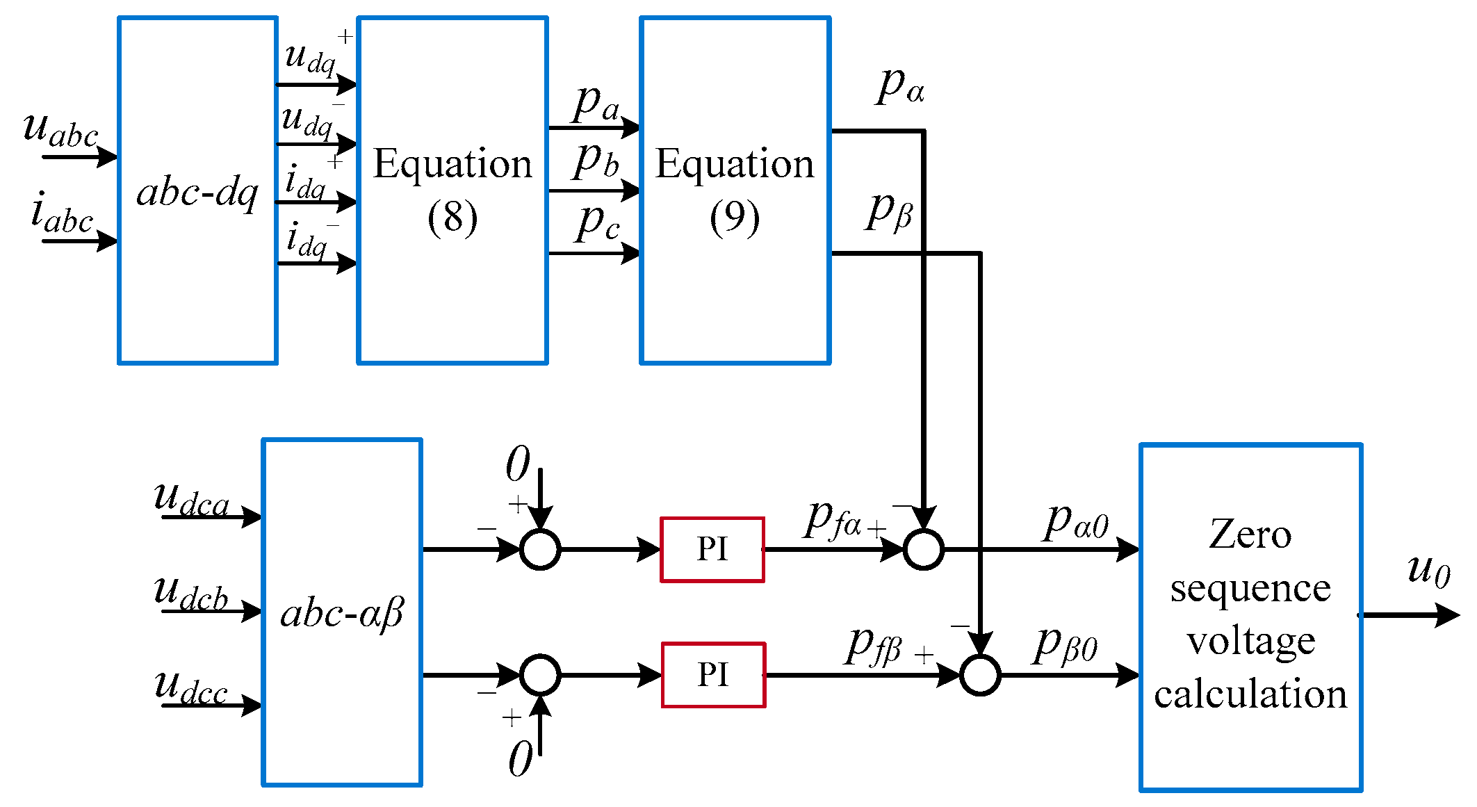
3.3. Zero-Sequence Voltage Feed-Forward Reference

Active power balance can be realized by injecting a zero-sequence voltage for a star-connected SVG. As shown in Equation (15), the zero-sequence voltage is not only related to the positive and negative-sequence voltage but also determined by the currents. According to the previous analysis, we can see that the zero-sequence voltage in APOE, RPOE, and BPSC are different. Since the negative-sequence current references are calculated according the three generalized current references calculation strategies, the feed-forward zero-sequence voltage reference can be calculated by submitting the current references into Equation (15).
In APOE, combining Equations (15) and (19), the zero-sequence voltage can be expressed as:
{ x = 2 u d + u d + u d 2 u d + u d u d + 2 u d + u q u q u d + u d + u d u d u q u q y = 2 u d + u d + u q 4 u d + u d u q u d + u d + u d u d u q u q
In RPOE, the zero-sequence voltage can be obtained as:
{ x = 0 y = 0
From Equation (24), it can be determined that there is no need to inject a zero-sequence voltage in RPOE mode. The moral is that the active power generated by the positive-sequence voltage with negative-sequence current is cancelled out by the one produced by the negative-sequence voltage with positive-sequence current in each phase.
When in BPSC, the zero-sequence voltage can be simplified as:
{ x = u d y = u q

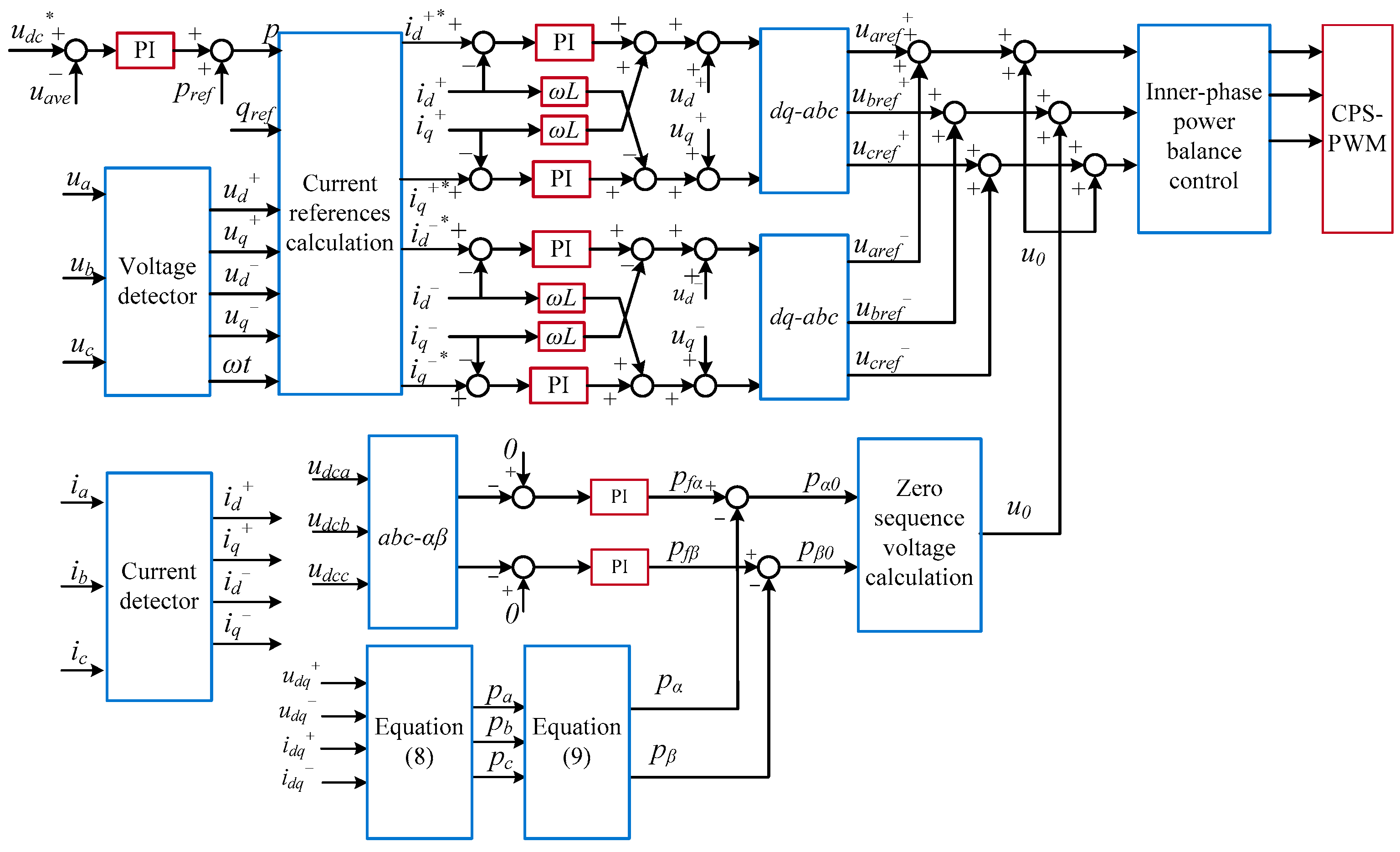
3.4. Control Strategy for a Star-Connected SVG

Based on the above analysis, a power control strategy is presented for a star-connected SVG as described in Figure 4. The power control strategy consists of phase current references calculation, power balance control and current tracking control. The references of active current id+, id, and reactive current iq+, iq, are calculated by Equations (19), (21), and (22) under different power control modes. Three parts are included in power balance control: overall power balancing control, inter-phase power balancing control and inner-phase power balancing control. The overall power balancing control maintains the summation of all capacitor voltage stable. The inter-phase power balancing control is achieved by injecting zero-sequence voltage component to redistribute the unbalanced active powers, as shown in Figure 3. The inner-phase power balancing control maintains the voltage balance of the sub-modules in each phase, sub-module capacitor voltage error is multiplied by each phase current synchronization signal after the P controller to obtain the power balancing control signal. The positive-sequence current component and negative-sequence current component are controlled separately in decoupled dual synchronous coordinate system. A carrier-phase-shifted PWM (CPS-PWM) modulation strategy is adopted in this paper.

4. Fault Ride-Through Capability of a Star-Connected SVG

4.1. Comparison in Maximum Phase Voltage

From the perspective of voltage stress and current stress, the fault ride through capability of SVG under three power control strategies will be compared and analyzed in following. As we know, the zero-sequence voltage injection will shift the virtual neutral point, which may cause the phase voltage to fluctuate, and even exceed a limit value that the SVG can be supplied. Thus, the maximum phase voltage is compared to analyze the fault ride through capability for the three power control strategies: APOE, RPOE, and BPSC.
The zero-sequence voltage injected for the three strategies are derived in the previous section, and the amplitude are shown in Figure 5 with the variation of asymmetrical voltage conditions for APOE and BPSC, while there is no need to inject for RPOE. From Figure 5, we can conclude that the zero-sequence voltage in APOE is always higher than BPSC.
According to the Kirchhoff’s voltage law, the positive and negative-sequence components of output voltages uaN, ubN, and ucN in the dq frame can be obtained by summing grid voltages and inductor voltages as follows:
[ U d + U q + ] = [ u d + u q + ] + ω L [ i q + i d + ] , [ U d U q ] = [ u d u q ] + ω L [ i q i d ]
After injection of zero-sequence voltage, the three-phase voltage can be expressed as:
u x N = u x O + u O N
Maximum phase voltage amplitude is defined as:
U max = max ( U a N , U b N , U c N )
where UaN, UbN, and UcN are three phase voltage amplitudes. Combining Equations (6) and (28), the maximum phase voltage amplitude can be calculated as:
{ U a N = ( U d + + U d + u d 0 ) 2 + ( U q + + U q + u q 0 ) 2 U b N = ( 1 2 U d + 1 2 U d + 3 2 U q + 3 2 U q + u d 0 ) 2 + ( 3 2 U d + + 3 2 U d 1 2 U q + 1 2 U q + u q 0 ) 2 U c N = ( 1 2 U d + 1 2 U d 3 2 U q + + 3 2 U q + u d 0 ) 2 + ( 3 2 U d + 3 2 U d 1 2 U q + 1 2 U q + u q 0 ) 2
In order to avoid over modulation, Umax should be satisfied:
U max M U d c r e f
where M is the maximum modulation index, in this paper, the CPS-PWM modulation strategy is used, and the value of M is 1.
Based on Equations (3) and (30), we can find that the maximum voltage amplitude is affected by the voltage unbalance factor k and negative sequence voltage phase angle θ. The relationship is as shown in Figure 6. The maximum voltage amplitude Umax increases as the voltage unbalance factor increases. Comparing Figure 6a–c, the RPOE can withstand greater voltage unbalance in the stable range, and the maximum phase voltage amplitudes of the three methods exhibit periodic changes.
Figure 7a,b shows the trend of the maximum phase voltage amplitude varying with the voltage unbalance factor k when θ is π/3 and 2π/3. It can be seen that with the increase of the voltage unbalance factor, Umax of the RPOE shows the least upward trend and exceeds the limit value after k = 0.5 in π/3 and k = 0.38 in 2π/3. Moreover, the Umax of APOE is far greater than BPSC when θ is π/3, and SVG is in the overmodulation state after k = 0.24, while APOE is approximately similar to BPSC when θ is 2π/3, overlapping in k = 0.38. The maximum phase voltage amplitude under three control strategies is shown in Figure 7c as the variation of θ when k is equal to 0.2. As shown, the maximum incidents happened when θ is 0, 2π/3, and 4π/3 for APOE, BPSC, and RPOE; by contrast, the minimal demands happened when θ is π/3, π, and 5π/3 for APOE, RPOE, and BPSC.

4.2. Comparison of the Maximum Phase Current

Since negative-sequence current is employed to achieve inter-phase power balancing and eliminate power oscillation, the phase currents may exceed the rated value, which will result in abnormal operation of the SVG and cause over-current protection. While the three power control strategies have different current values, the three-phase maximum phase current of the three power control strategies is compared to analyze the fault ride through capability. The standardized maximum phase current is normalized as:
I max , s = | I max | | I p u |
where Ipu = Qref/u+ is the amplitude value of positive-sequence current under symmetrical conditions. According to Equations (3) and (17), we can conclude that the maximum current amplitude is highly correlated to the voltage unbalance factor k and the negative sequence voltage phase angle θ. The relationships are as shown in Figure 8. With the increase of unbalance factor, the maximum current amplitude of APOE and RPOE increase gradually, which may cause overcurrent problems. In the low unbalance factor, APOE has larger current value than RPOE, and RPOE has the largest current value in high unbalance factor condition. The current obtained by BPSC is only related to the positive-sequence voltage and reactive power reference, so it remains unchanged. Simultaneously, the maximum current amplitude of the APOE and RPOE change periodically with a period of 2π/3.
Based on the above analysis, it is known that the fault ride through capability of three power control strategies, APOE, RPOE, and BPSC, are different. From the zero-sequence voltage point of view, the RPOE does not need to inject the zero-sequence voltage, and the APOE needs the largest amplitude. From the perspective of the maximum phase voltage, the APOE voltage stress is the largest and the RPOE voltage stress is the smallest. In the view of maximum phase current, the current of BPSC is symmetrical and the current stress of RPOE is the largest.

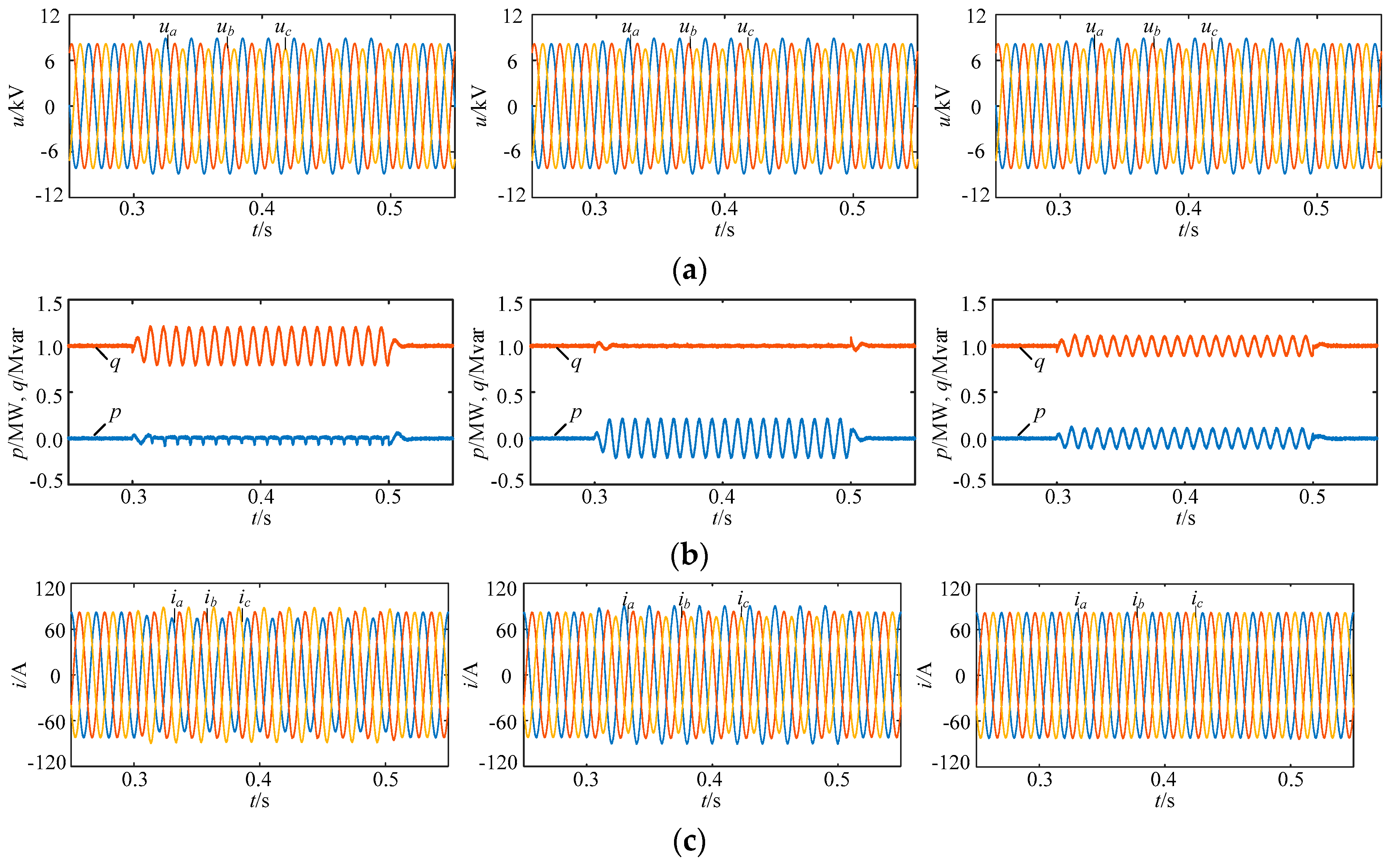
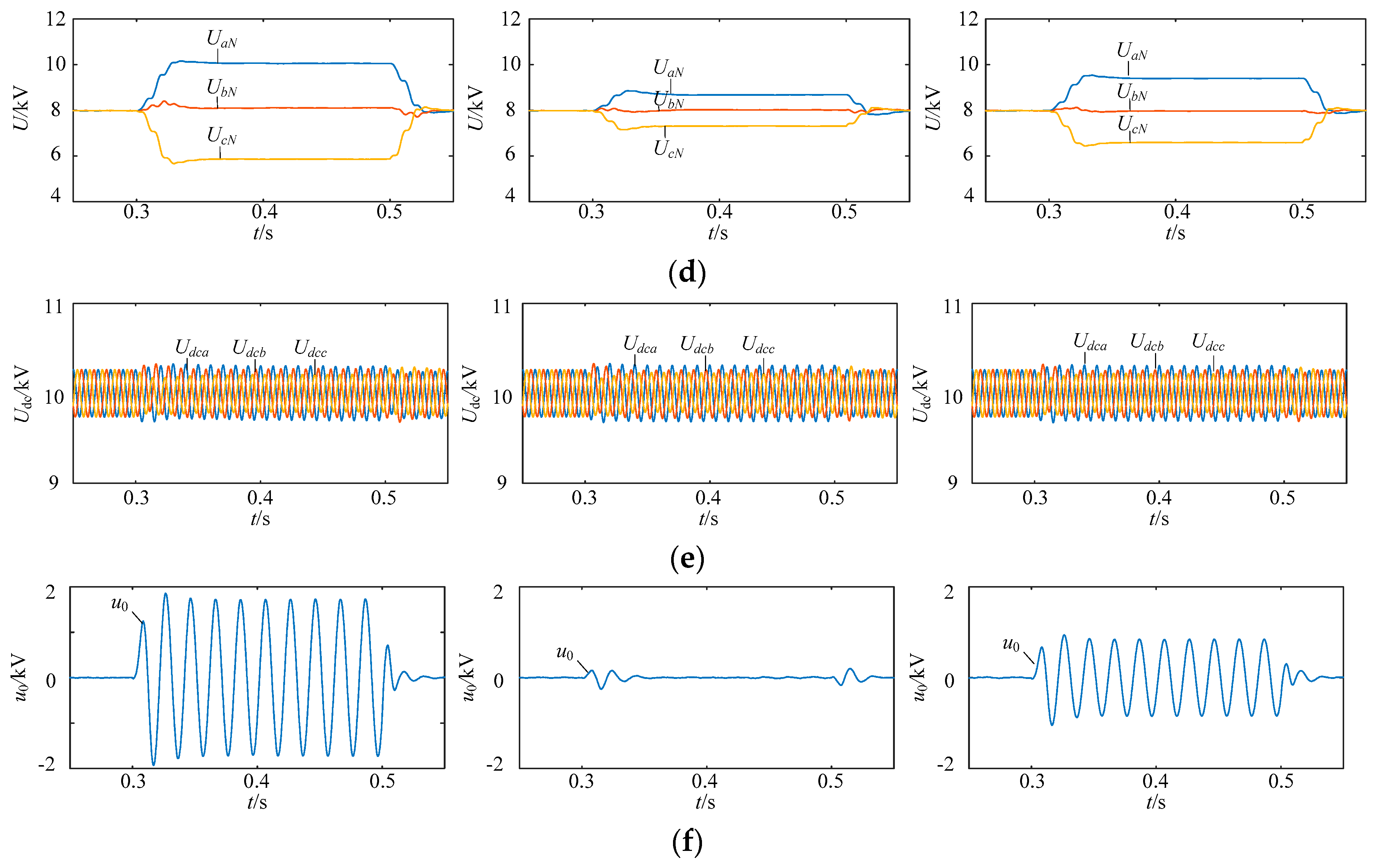
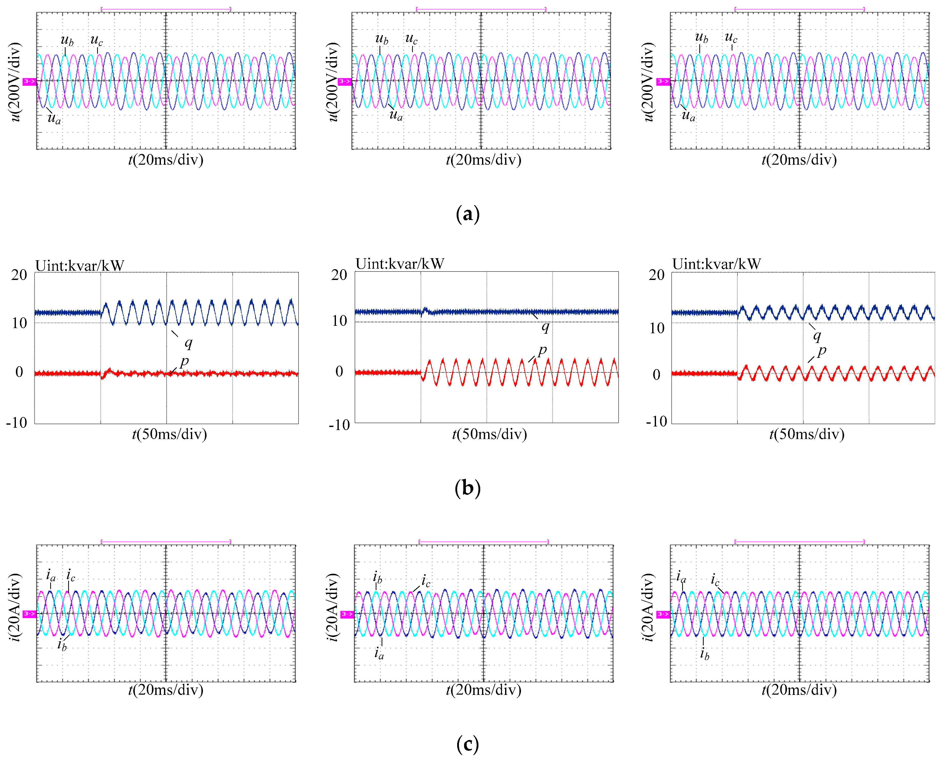
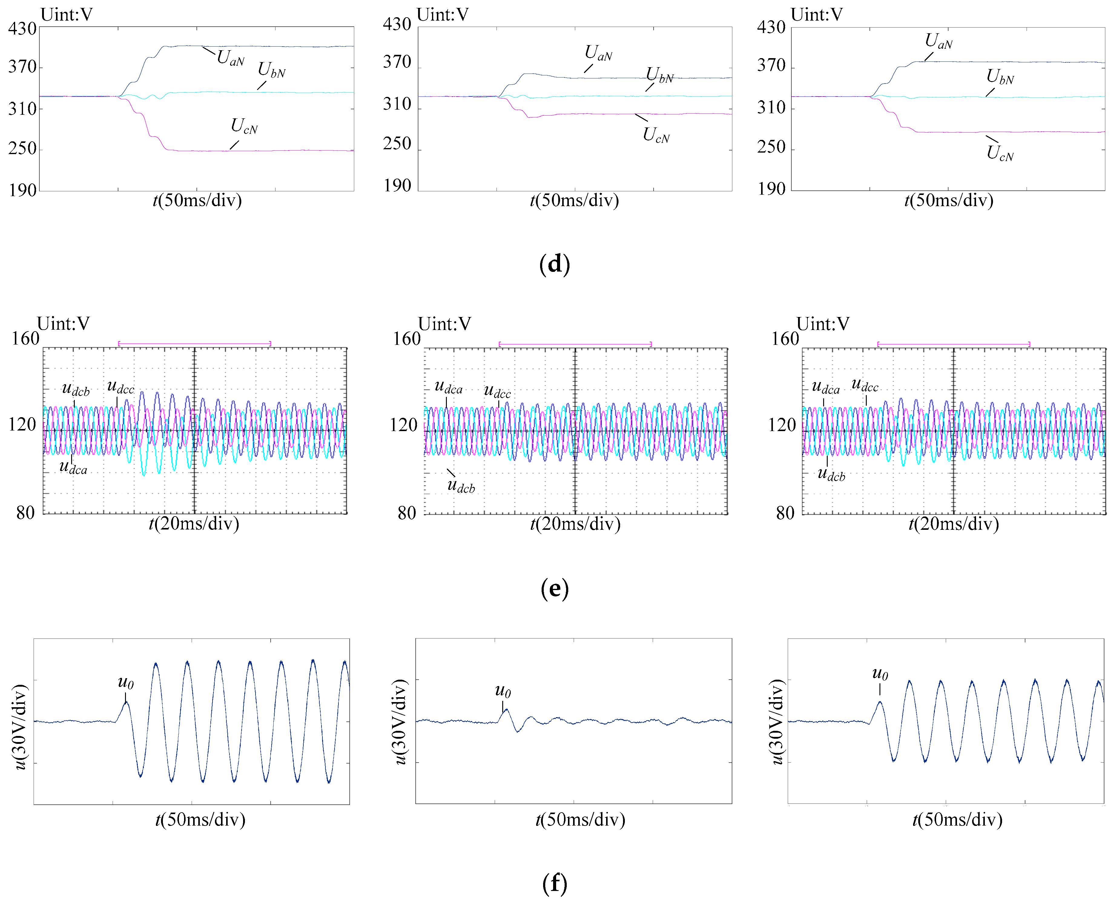
5. Simulation and Experiment Results

In order to verify the proposed control strategy, and compare the fault ride through capability in APOE, RPOE, and BPSC, a star-connected 10 kV/1 Mvar SVG simulation is performed in MATLAB (R2011b, The MathWorks, Inc, Natick, MA, USA).and an experiment platform is built and verified with RT-LAB. Parameters of simulation and experiment were listed in Table 1. The circuit structure of SVG adopted for simulation and experiment shown in Figure 1. And the control strategies used for simulation and experiment shown in Figure 4.
In the simulation, the negative voltage is injected between 0.3 s and 0.5 s, and its amplitude and phase angle are set as 816 V and π/6. Under this condition, the unbalance grid voltage factor k is about 10%. Reactive power reference is set as 1 Mvar. The simulation results of the three cases were shown in Figure 9. The simulation results of APOE are shown in the left side of Figure 9, that for RPOE are shown in the middle of Figure 9, and the others are the simulation results of BPSC. The asymmetrical grid voltages are shown in Figure 9a. The instantaneous active and reactive power of SVG are presented as Figure 9b and the phase currents of SVG are shown in Figure 9c. It can be seen that the active power oscillation is eliminated for APOE and the reactive power oscillation is eliminated for RPOE, while the phase currents are unbalanced both for APOE and RPOE. The phase currents are kept balanced while both active and reactive powers have oscillation for BPSC. The three phase voltage amplitudes and zero-sequence voltage of SVG are shown in Figure 9d,e, respectively. The phase voltage amplitude for APOE had the maximum values because it employed the largest zero-sequence voltage. As shown in Figure 9f, the capacitor voltage summations of the three-phase are kept balanced with the proposed control method when the voltages became asymmetrical. Since zero-sequence voltage injection is introduced in the proposed method, small voltage overshoots occur during the grid voltage dynamic process, therefore, the proposed method shows good capacitor voltage control performance.
Table 2 shows the quantitative comparison between analytical results and simulation results where the amplitude and phase angle of the injected negative voltage are also set as 816 V and π/6. The analytical result of zero-sequence voltage is obtained from Equations (23)–(25). The analytical result of maximum voltage is obtained from Equations (3) and (30). The analytical result of maximum current is obtained from Equations (3) and (17). It can be seen from the Table 2 that analytical results and simulation results are very closely which verified the effectiveness of the theoretical analysis in the paper.
The experiment was operated on the RT-LAB device(Opal-RT, Montreal, QC, Canada), the power devices were implemented in the RT-LAB platform from Opal-RT Technologies, the real control hardware DSP-TMS320F2812 (Texas Instruments, Dallas, TX, USA) and FPGA-EP2C8 (Altera Corporation, California, USA) are utilized in the main board to execute the control algorithm. Experiment results of the system are divided to three columns shown in Figure 10. APOE is shown in the left, RPOE in the middle, and BPSC in the right. According to the experiment results, comparison of the three strategies is shown in Table 3.
Figure 10a shows the asymmetrical grid voltages, the voltages become asymmetrical after 5 0ms after the negative sequence voltage was added. The negative voltage amplitude is set as 30 V and the angle is set as π/6. Then the unbalanced degree of grid voltage is near 10%. Reactive power reference is set as 12 Kvar in this experiment.
The instantaneous active power and reactive power for APOE, RPOE, and BPSC of SVG are shown in Figure 10b. For APOE, the active power component is kept almost constant under asymmetric conditions, so that the active power oscillation is eliminated for APOE. For RPOE the reactive power oscillation is eliminated because the reactive power component is kept almost constant under asymmetric conditions. However, for BPSC both active and reactive powers have oscillations Figure 10c shows the phase current of SVG, the phase currents are balanced for BPSC, while the phase currents obtained by APOE and RPOE are asymmetrical, and the phase current amplitude obtained by RPOE has the largest value while it has minimum values as shown in Table 3. Figure 10d shows the three-phase voltage amplitudes of three cases, since the zero-sequence voltage is employed, the three-phase voltage amplitudes has different values. While, the voltage amplitude for APOE has the maximum values, which is consistent with the above analysis results. The capacitor voltages of one sub-module in the three-phase are shown in Figure 10e, capacitor voltages are kept balanced with the proposed control method even in the asymmetrical voltage conditions, small voltage step are occurred during the dynamic process. The zero-sequence voltages calculated by the proposed method are shown in Figure 10f. The zero-sequence voltage for APOE is the largest, while it becomes zero in RPOE.

6. Conclusions

The inter-phase power unbalanced problem of the star-connected SVG under asymmetrical conditions is investigated. First, the unbalanced active power is analyzed in the αβ frame. Combined with the phasor analysis, the zero-sequence voltage expression is derived. Then, a power balance control method based on zero-sequence voltage feed-forward is given. The zero-sequence voltage expression is calculated directly by the extracted positive and negative sequence voltage direct component and current references, so that the dynamic performance of the SVG power balance control can be improved under asymmetrical conditions. On the basis of this, from the perspective of the zero-sequence voltage, maximum phase voltage and maximum phase current, the fault ride through capability of star-connected SVG under asymmetrical conditions was compared in three strategies include APOE, RPOE, and BPSC. The method provides the theoretical reference for power control under asymmetric conditions. The analysis results show that under asymmetrical conditions, the current of BPSC is minimal and symmetrical, while the RPOE has the least voltage and no zero- sequence voltage needs to be injected. Finally, the results of simulation and experiment have been given to verify the theoretical studies.

Author Contributions

All the authors conceived and designed the study. Conceptualization: M.X. and Z.H.; methodology: M.X., Z.H., and H.O.; software: F.W.; validation: F.W., R.H., and Q.X.; formal analysis: F.W. and Z.H.; writing—original draft preparation: M.X.; writing—review and editing: Z.H.

Funding

This work was supported by the National Natural Science Foundation of China (NSFC) under grant no. 51677063.

Conflicts of Interest

The authors declare no conflict of interest.

References

  1. Kouro, S.; Leon, J.I.; Vinnikov, D.; Franquelo, L.G. Grid-connected photovoltaic systems: An overview of recent research and emerging PV converter technology. IEEE Ind. Electron. Mag. 2015, 9, 47–61. [Google Scholar] [CrossRef]
  2. Blaabjerg, F.; Teodorescu, R.; Liserre, M.; Timbus, A.V. Overview of control and grid synchronization for distributed power generation systems. IEEE Trans. Ind. Electron. 2006, 53, 1398–1409. [Google Scholar] [CrossRef]
  3. Fuentes, C.D.; Rojas, C.A.; Renaudineau, H.; Kouro, S.; Perez, M.A.; Thierry, M. Experimental validation of a single dc bus cascaded H-bridge multilevel inverter for multistring photovoltaic systems. IEEE Trans. Ind. Electron. 2016, 64, 930–934. [Google Scholar] [CrossRef]
  4. Milczarek, A.; Malinowski, M.; Guerrero, J.M. Reactive power management in islanded microgrid—Proportional power sharing in hierarchical droop control. IEEE Trans. Smart Grid 2015, 6, 1631–1638. [Google Scholar] [CrossRef]
  5. Muñoz, J.A.; Espinoza, J.R.; Baier, C.R.; Morán, L.A.; Guzmán, J.I.; Cárdenas, V.M. Decoupled and Modular Harmonic Compensation for Multilevel STATCOMs. IEEE Ind. Electron. Mag. 2014, 61, 2743–2753. [Google Scholar] [CrossRef]
  6. Lee, T.; Hu, S.; Chan, Y. D-STATCOM with positive-sequence admittance and negative-sequence conductance to mitigate voltage fluctuations in high-level penetration of distributed-generation systems. IEEE Ind. Electron. Mag. 2013, 60, 1417–1428. [Google Scholar] [CrossRef]
  7. Camacho, A.; Castilla, M.; Miret, J.; Borrell, A.; de Vicuña, L.G. Active and reactive power strategies with peak current limitation for distributed generation inverters during unbalanced grid faults. IEEE Ind. Electron. Mag. 2015, 62, 1515–1525. [Google Scholar] [CrossRef]
  8. Sivaranjani, R. StatCom control at wind farms with fixed-speed induction generators under asymmetrical grid faults. In Proceedings of the 2016 International Conference on Electrical, Electronics, and Optimization Techniques (ICEEOT), Chennai, India, 3–5 March 2016; pp. 3442–3447. [Google Scholar] [CrossRef]
  9. Akagi, H.; Inoue, S.; Yoshii, T. Control and performance of a transformerless cascade PWM STATCOM with star configuration. IEEE Trans. Ind. Appl. 2007, 43, 1041–1049. [Google Scholar] [CrossRef]
  10. Peng, F.Z.; Lai, J. Dynamic performance and control of a static VAr generator using cascade multilevel inverters. IEEE Trans. Ind. Appl. 1997, 33, 748–755. [Google Scholar] [CrossRef]
  11. Hatano, N.; Ise, T. Control scheme of cascaded H-Bridge STATCOM using zero-sequence voltage and negative-sequence current. IEEE Trans. Power. Deliv. 2010, 25, 543–550. [Google Scholar] [CrossRef]
  12. Zhixing, H.; Fujun, M.; An, L.; Qianming, X.; Yandong, C.; Huagen, X.; Guobin, J. Circulating current derivation and comprehensive compensation of cascaded STATCOM under asymmetrical voltage conditions. IET Gener. Transm. Distrib. 2016, 10, 2924–2932. [Google Scholar] [CrossRef]
  13. Chen, H.; Wu, P.; Lee, C.; Wang, C.; Yang, C.; Cheng, P. Zero-sequence voltage injection for dc capacitor voltage balancing control of the star-connected cascaded H-Bridge PWM converter under unbalanced grid. IEEE Trans. Ind. Appl. 2015, 51, 4584–4594. [Google Scholar] [CrossRef]
  14. Akagi, H. Multilevel converters: Fundamental circuits and systems. Proc. IEEE 2017, 105, 2048–2065. [Google Scholar] [CrossRef]
  15. Gultekin, B.; Ermis, M. Cascaded multilevel converter-based transmission STATCOM: System design methodology and development of a 12 kV ± 12 Mvar power stage. IEEE Ind. Electron. Mag. 2013, 28, 4930–4950. [Google Scholar] [CrossRef]
  16. Akagi, H. Classification, terminology, and application of the modular multilevel cascade converter (MMCC). IEEE Trans. Power Electron. 2011, 26, 3119–3130. [Google Scholar] [CrossRef]
  17. Shi, Y.; Liu, B.; Shi, Y.; Duan, S. Individual phase current control based on optimal zero-sequence current separation for a star-connected cascade STATCOM under unbalanced conditions. IEEE Ind. Electron. Mag. 2016, 31, 2099–2110. [Google Scholar] [CrossRef]
  18. Betz, R.E.; Summers, T.; Furney, T. Symmetry compensation using a H-bridge multilevel STATCOM with zero sequence injection. In Proceedings of the Conference Record of the 2006 IEEE Industry Applications Conference Forty-First IAS Annual Meeting, Tampa, FL, USA, 8–12 October 2006; Volume 4, pp. 1724–1731. [Google Scholar]
  19. Song, Q.; Liu, W. Control of a cascade STATCOM with star configuration under unbalanced conditions. IEEE Trans. Power Electron. 2009, 24, 45–58. [Google Scholar] [CrossRef]
  20. Ota, J.I.Y.; Shibano, Y.; Niimura, N.; Akagi, H. A phase-shifted-PWM D-STATCOM using a modular multilevel cascade converter (SSBC)—Part I: Modeling, analysis, and design of current control. IEEE Trans. Ind. Appl 2015, 51, 279–288. [Google Scholar] [CrossRef]
  21. Behrouzian, E.; Bongiorno, M. Investigation of negative-sequence injection capability of cascaded H-bridge converters in star and delta configuration. IEEE Trans. Power Electron. 2017, 32, 1675–1683. [Google Scholar] [CrossRef]
  22. Lu, D.; Wang, J.; Yao, J.; Wang, S.; Zhu, J.; Hu, H.; Zhang, L. Clustered voltage balancing mechanism and its control strategy for star-connected cascaded H-Bridge STATCOM. IEEE Trans. Ind. Electron. 2017, 64, 7623–7633. [Google Scholar] [CrossRef]
  23. Hatano, N.; Ise, T. A configuration and control method of cascade H-bridge STATCOM. In Proceedings of the IEEE Power Energy Society General Meeting, Pittsburgh, PA, USA, 20 July 2008. [Google Scholar] [CrossRef]
  24. Lee, C.T.; Wang, B.S.; Chen, S.W.; Chou, S.F.; Huang, J.L.; Cheng, P.T.; Akagi, H.; Barbosa, P. Average power balancing control of a STATCOM based on the cascaded H-bridge PWM converter with star configuration. In Proceedings of the 2013 IEEE Energy Conversion Congress and Exposition, Denver, CO, USA, 15–19 September 2013; pp. 970–977. [Google Scholar] [CrossRef]
Figure 1. Topology of the star-connected SVG.
Energies 12 02361 g001
Figure 2. Phasor diagram of the star-connected SVG.
Energies 12 02361 g002
Figure 3. Control block of inter-phase power balancing control.
Energies 12 02361 g003
Figure 4. The power control strategy of a star-connected SVG.
Energies 12 02361 g004
Figure 5. Relationships among the zero-sequence voltage amplitude, unbalanced factor and the phase angle of the negative sequence voltage. (a) APOE. (b) BPSC.
Energies 12 02361 g005
Figure 6. Relationships among the maximum voltage amplitude, unbalanced factor and the phase angle of negative sequence voltage. (a) APOE. (b) RPOE. (c) BPSC.
Energies 12 02361 g006
Figure 7. Relationships among the maximum voltage amplitude, unbalanced factor and the phase angle of negative sequence voltage. (a) When θ is π/3. (b) When θ is 2π/3. (c) When k is 0.2.
Energies 12 02361 g007
Figure 8. Relationships among the maximum current amplitude, unbalanced factor and the phase angle of the negative sequence voltage. (a) APOE. (b) RPOE. (c) BPSC.
Energies 12 02361 g008
Figure 9. Simulation results of star-connected SVG. APOE in the left. RPOE in the middle. BPSC in the right. (a) Grid voltages. (b) Active and reactive power. (c) Phase currents of SVG. (d) Three-phase voltage amplitudes. (e) Zero-sequence voltages. (f) Sub-module capacitor voltages of each phase cluster.
Energies 12 02361 g009aEnergies 12 02361 g009b
Figure 10. Experiment results of star-connected SVG. APOE in the left. RPOE in the middle. BPSC in the right. (a) Grid voltages. (b) Active and reactive power. (c) Phase currents of SVG. (d) three-phase voltage amplitudes. (e) Sub-module capacitor voltages of each phase cluster. (f) Zero-sequence voltages.
Energies 12 02361 g010aEnergies 12 02361 g010b
Table 1. Main parameters of the system.
ParameterSimulationExperiment
The grid line voltage/V10k380
DC voltage/V10k480
Cascaded number104
AC filter inductor/mH81
DC capacitor/uF22001100
Carrier frequency/kHz28
Table 2. Comparison between analytical results and simulation results.
ItemsAPOERPOEBPSC
AnalyticalSimulationAnalyticalSimulationAnalyticalSimulation
Maximum current 88 A87 A90 A90 A82 A82 A
Maximum voltage 10.01 kV10.06 kV8.69 kV8.67 kV9.37 kV9.40 kV
Zero-sequence voltage 1.66 kV1.72 kV00.02 kV0.82 kV0.85 kV
Table 3. Comparison of three strategies.
ItemsAPOERPOEBPSC
Active powerNo oscillationOscillationOscillation
Reactive powerOscillationNo oscillationOscillation
Phase current
Zero-sequence voltage
Unbalanced
58 V
Unbalanced
0 V
Balanced
29 V
Maximum voltage401 V355 V376 V
Maximum current28.5 A29.2 A25.7 A

