Influence of Geometric Parameters of Alternate Axis Twisted Baffles on the Local Heat Transfer Distribution and Pressure Drop in a Rectangular Channel Using a Transient Liquid Crystal Technique


Abstract
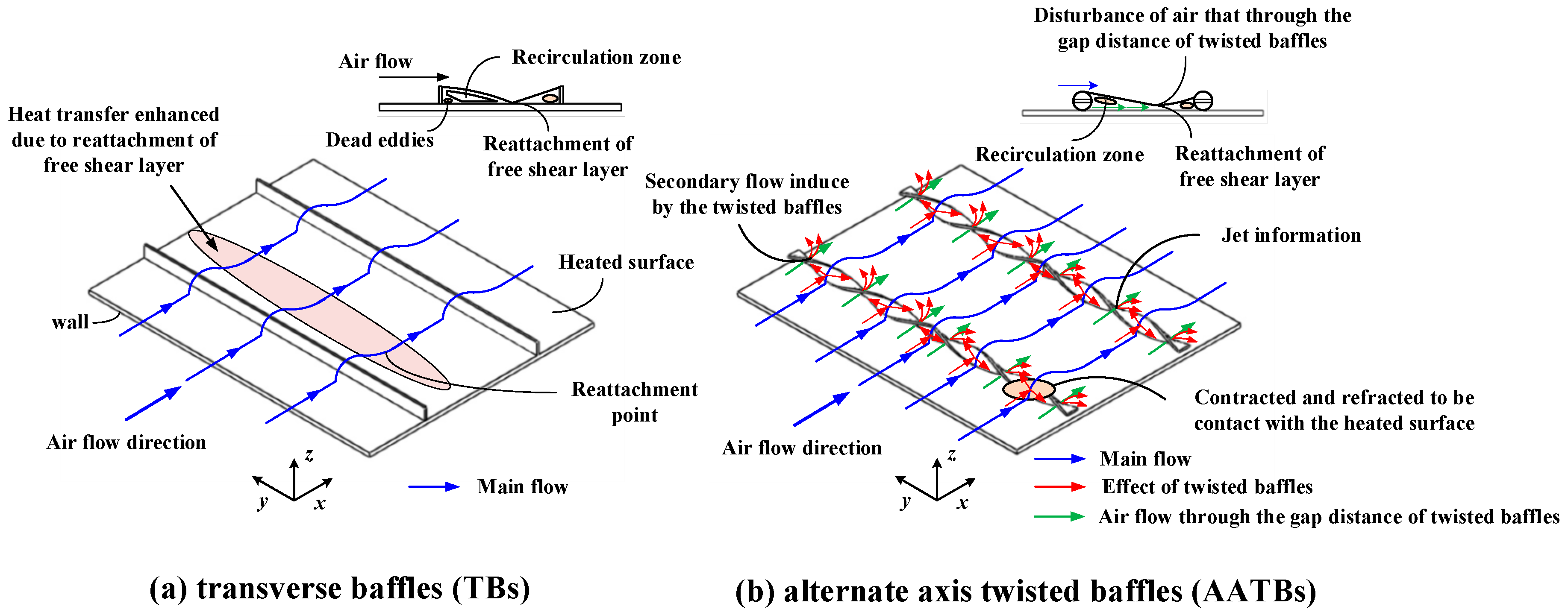
:1. Introduction
2. Thermochromic Liquid Crystals
2.1. Molecular Structure of TLCs
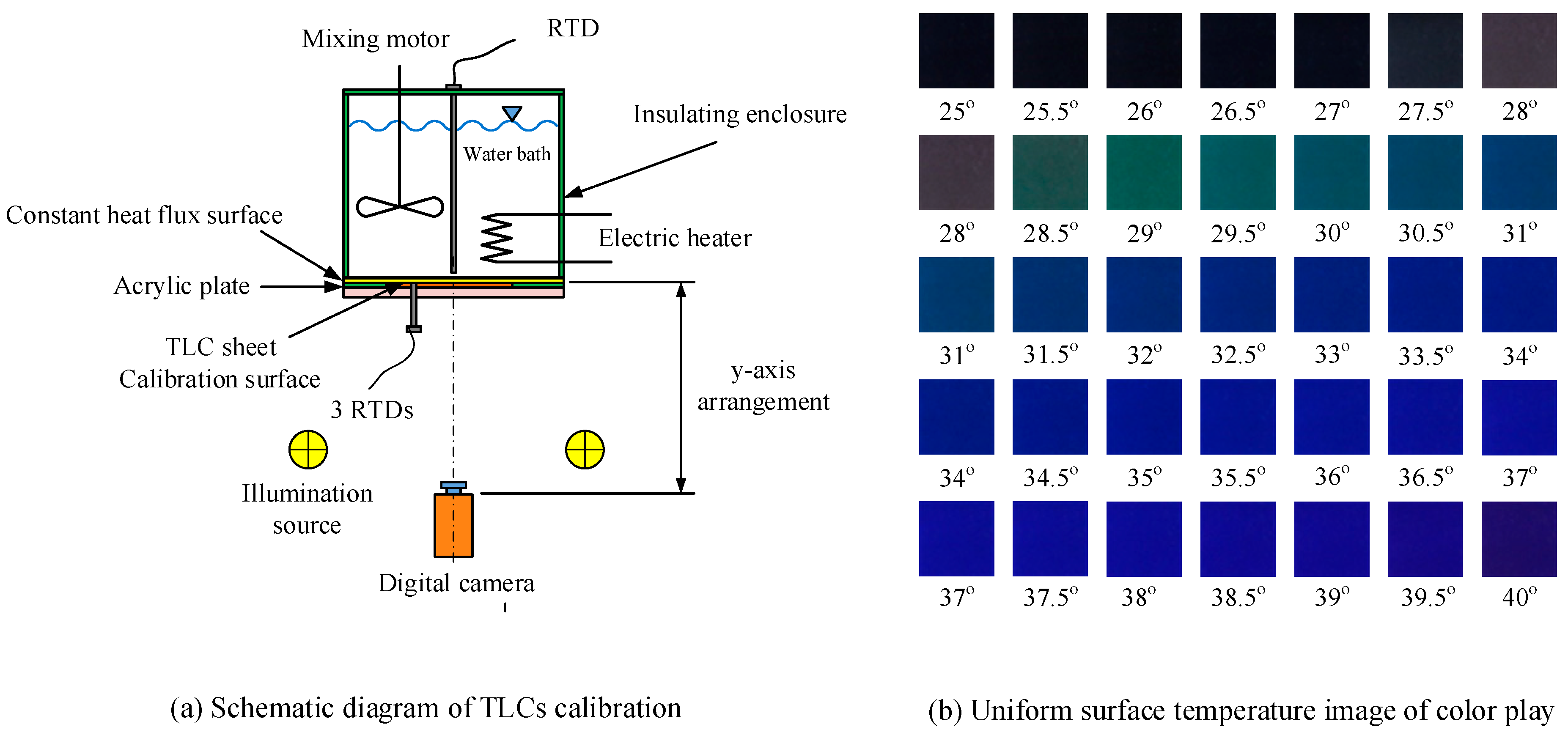
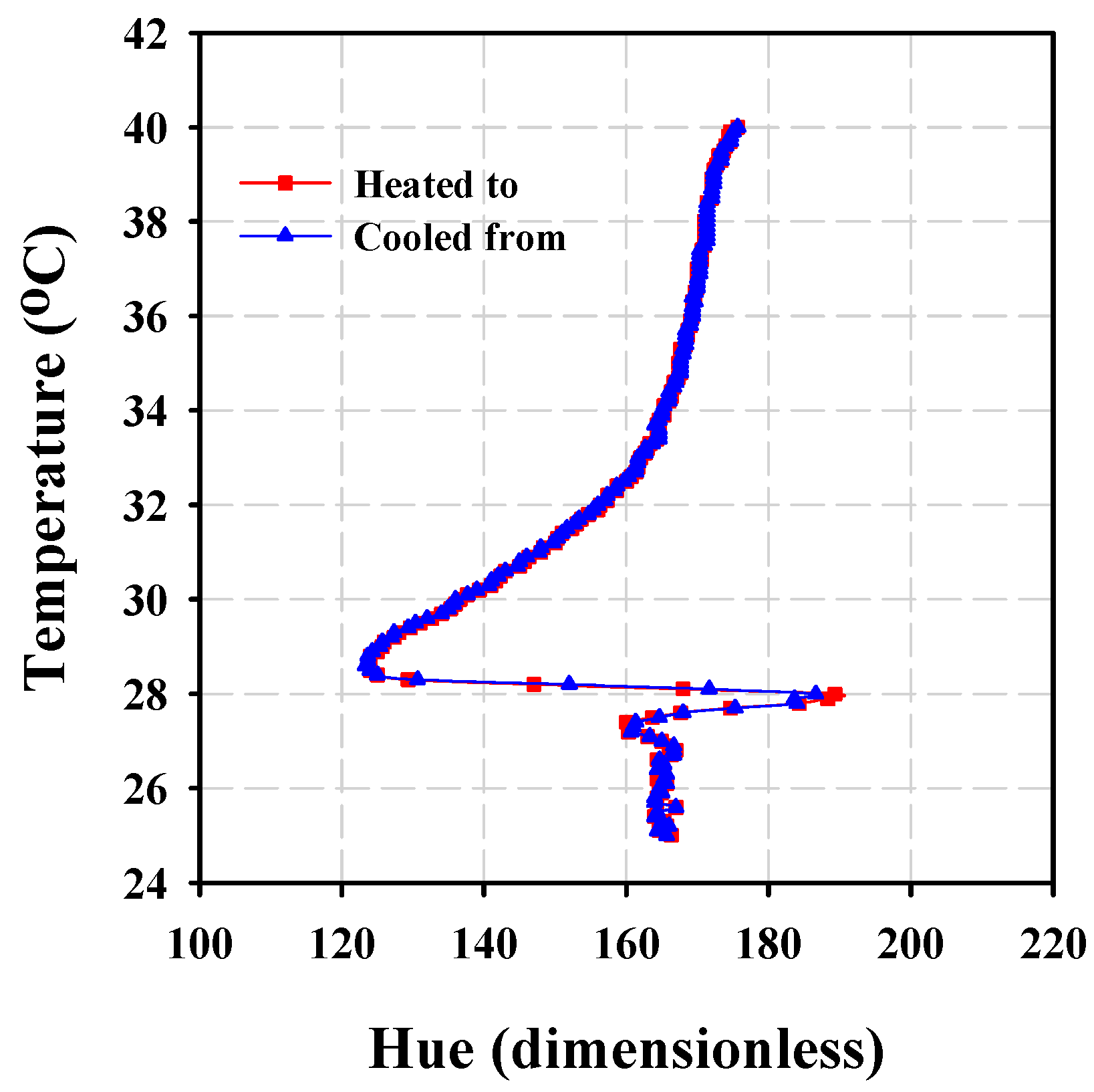
2.2. TLC Calibration
2.3. Imaging System
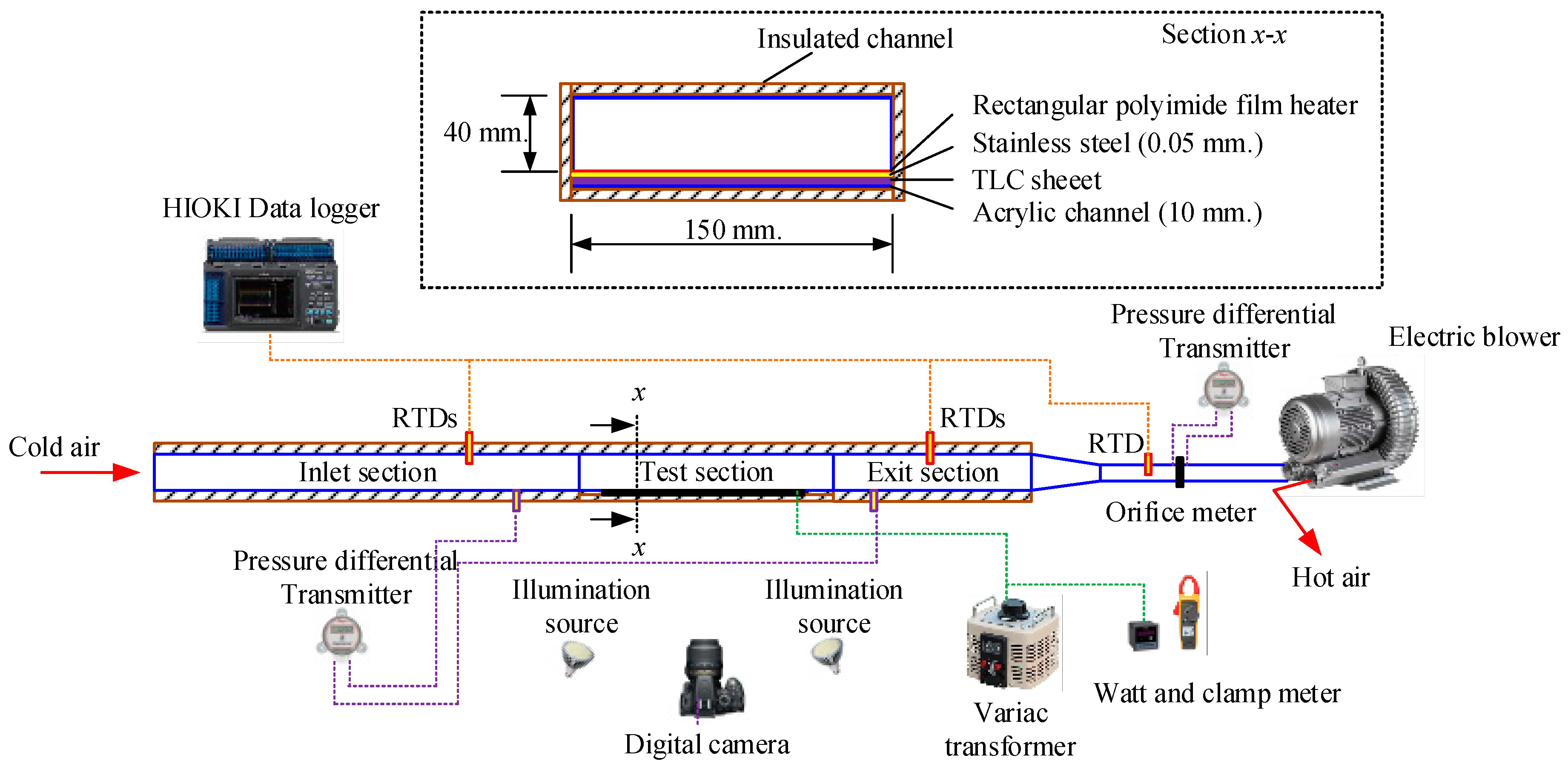
3. Experimental Apparatus and Its Operation
4. Data Reduction
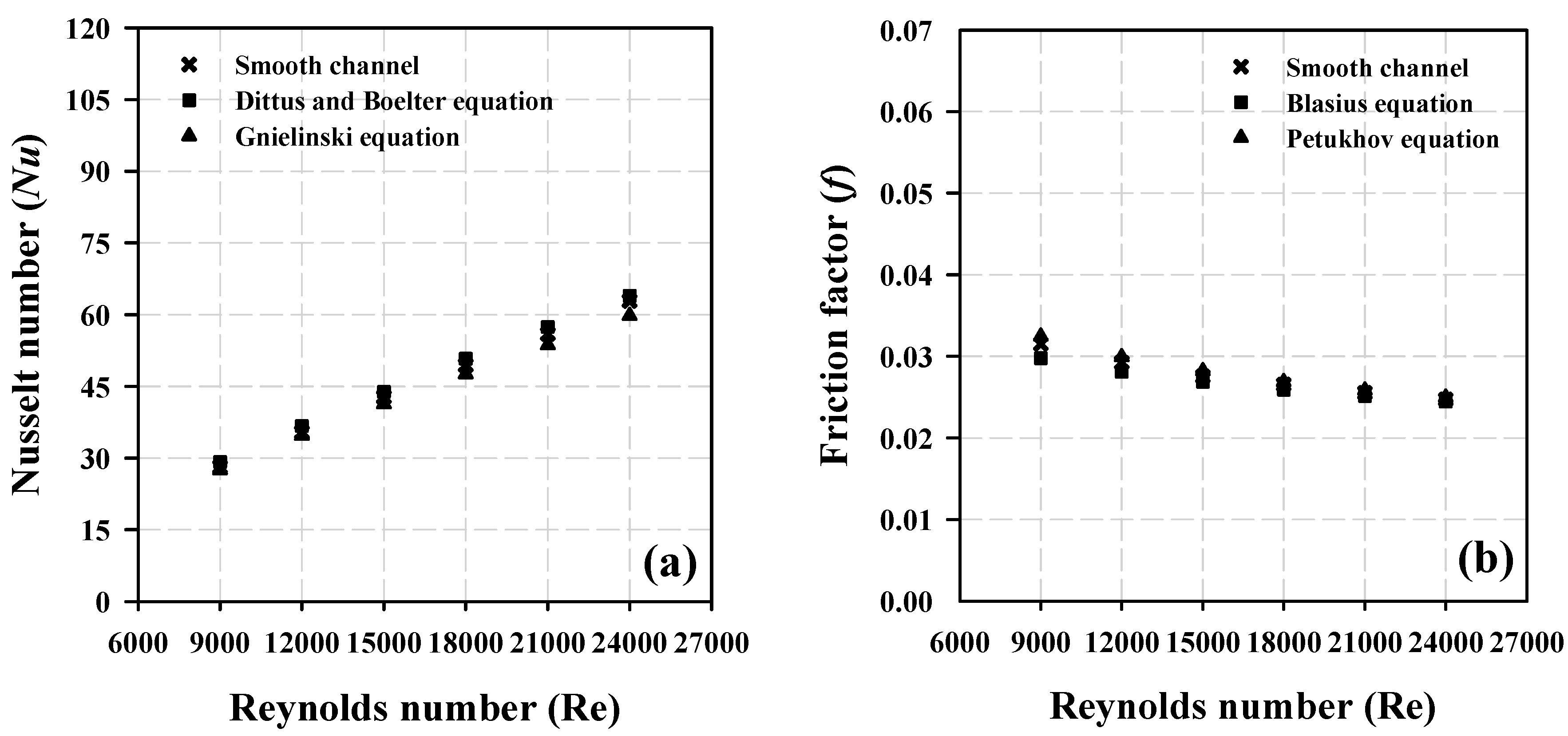
5. Validity Test of the Experiment Setup
- (a)
- Dittus–Boelter equation (for 6000 ≤ Re ≤ 5 × 10⁷ and 0.5 ≤ Pr ≤ 120)
- (b)
- Gnielinski equation (for 3000 ≤ Re ≤ 5 × 10⁶)
- (c)
- Modified Blasius equation
- (d)
- Pethkhov equation
6. Results and Discussion
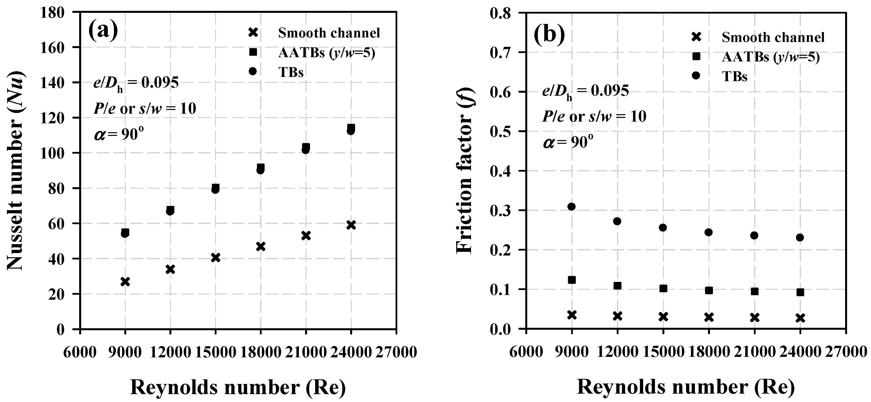
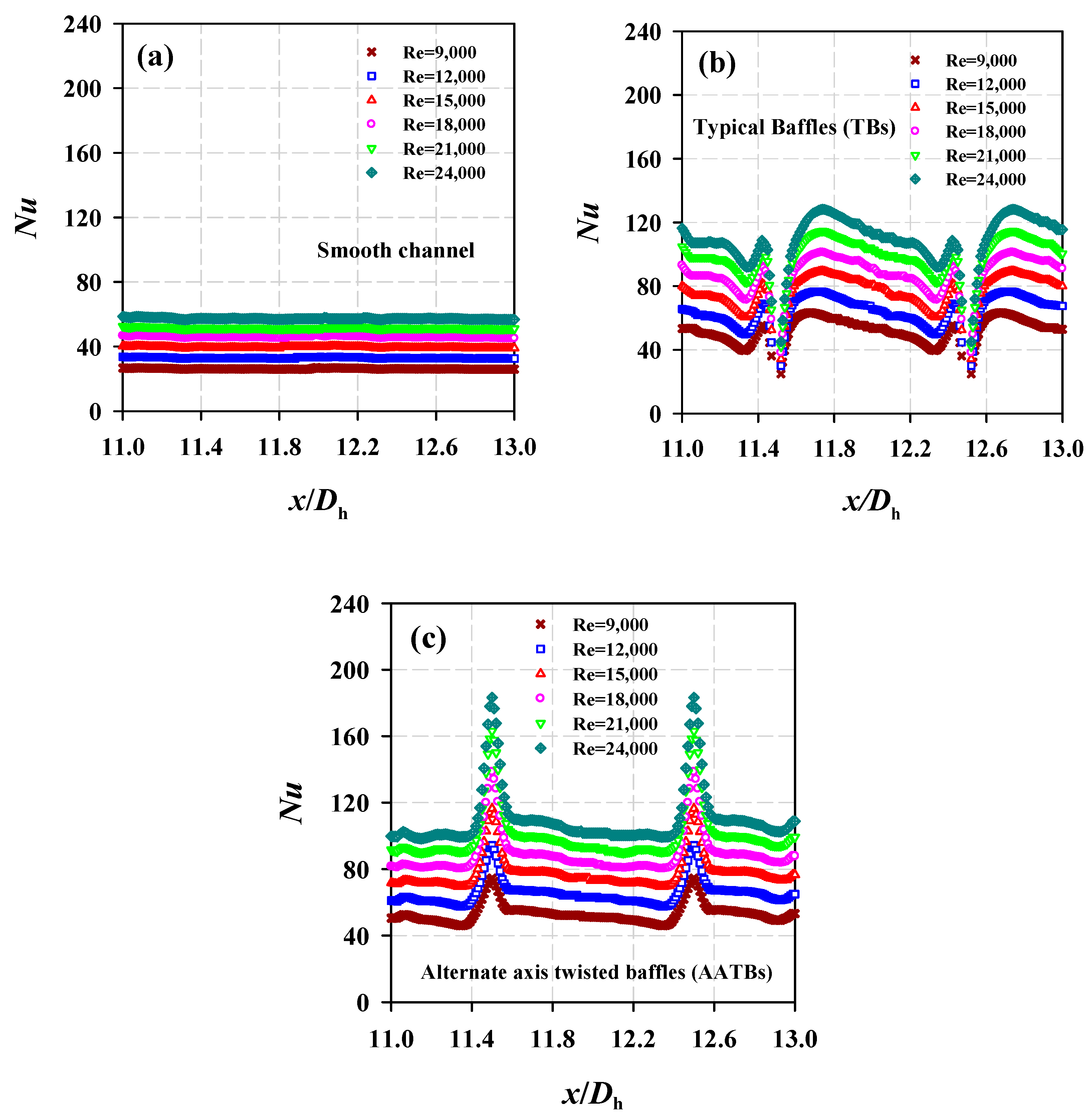
6.1. The Effect of Reynolds Number (Re)
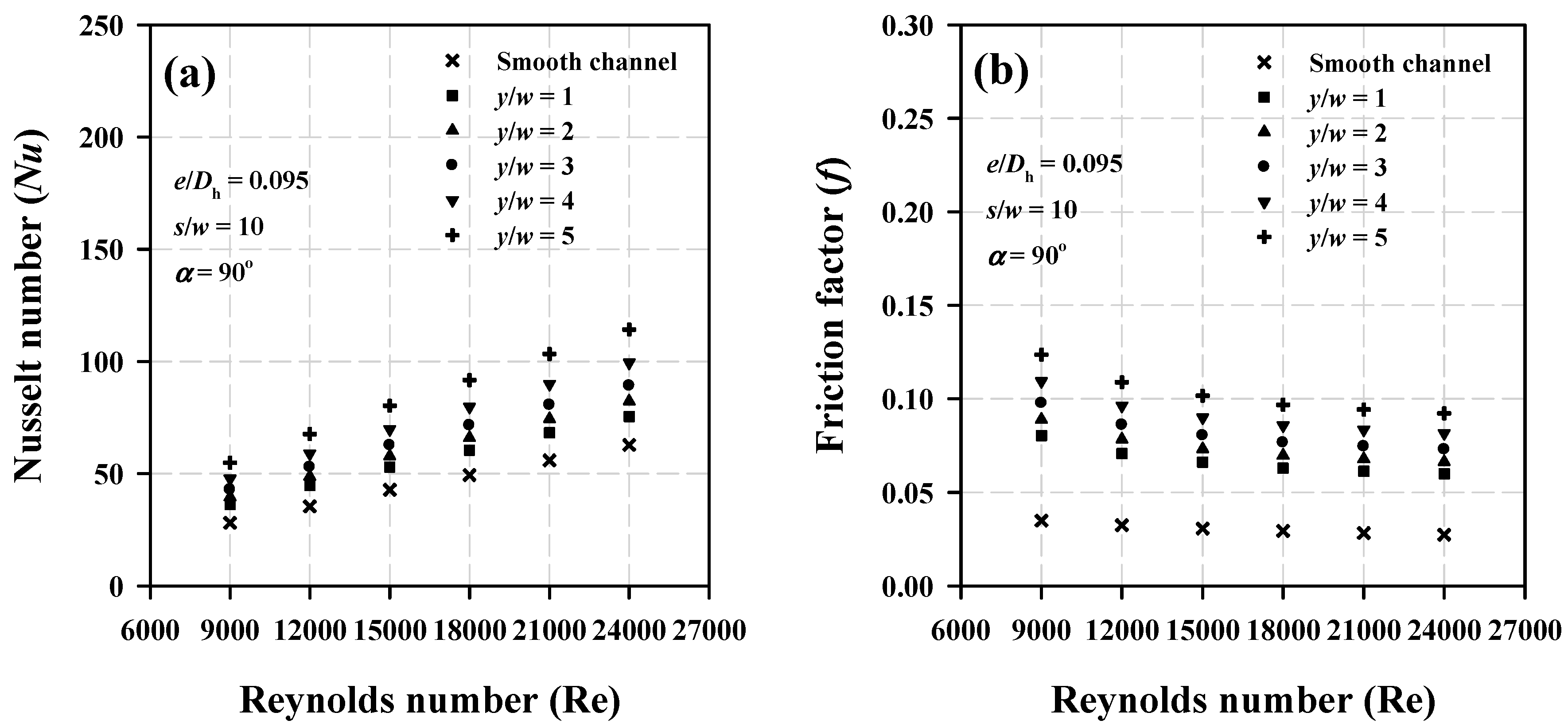
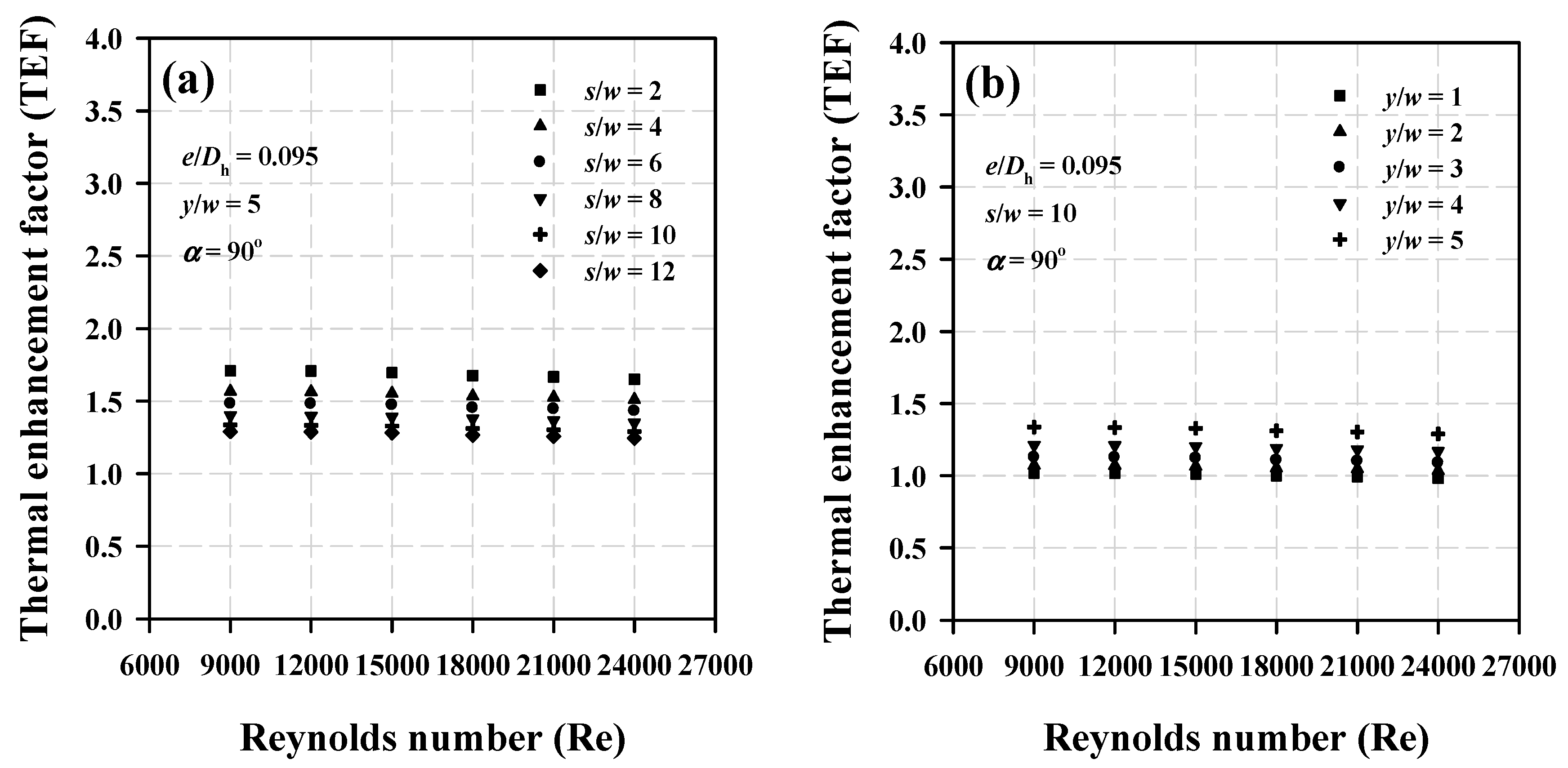
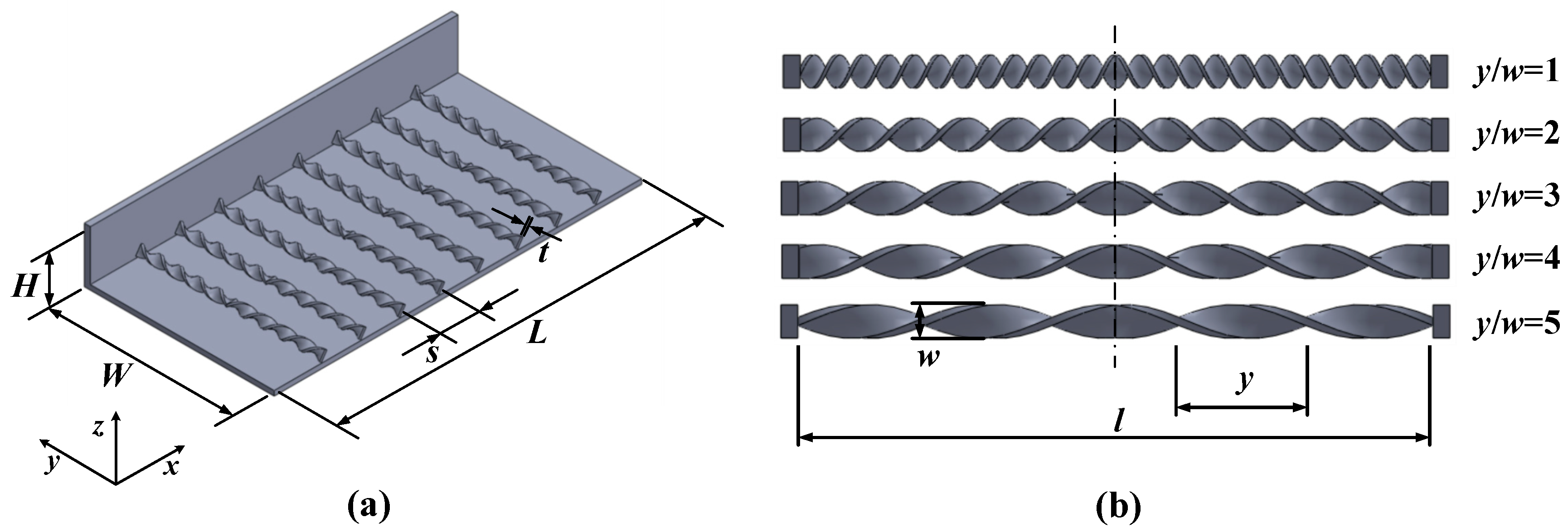
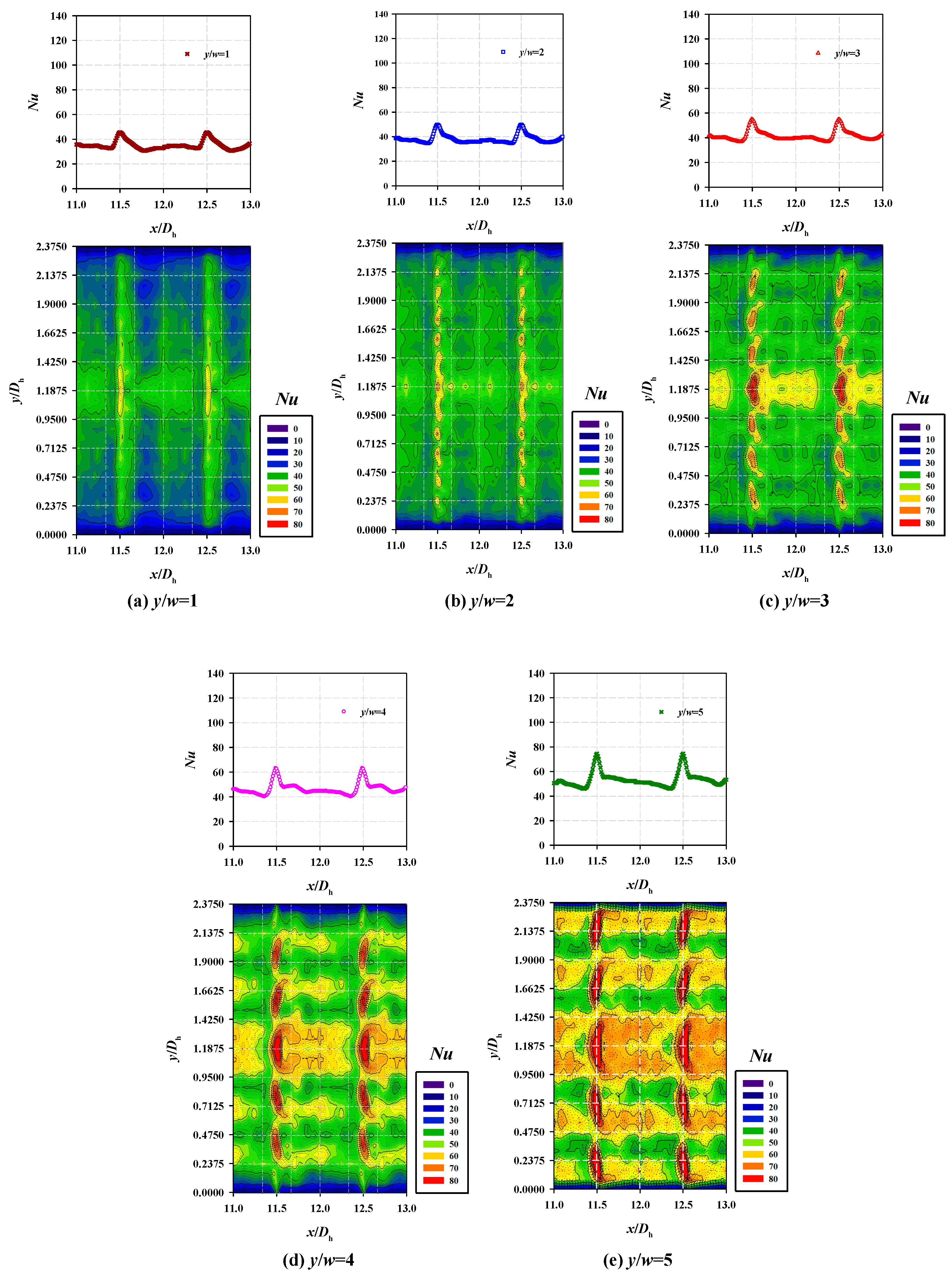
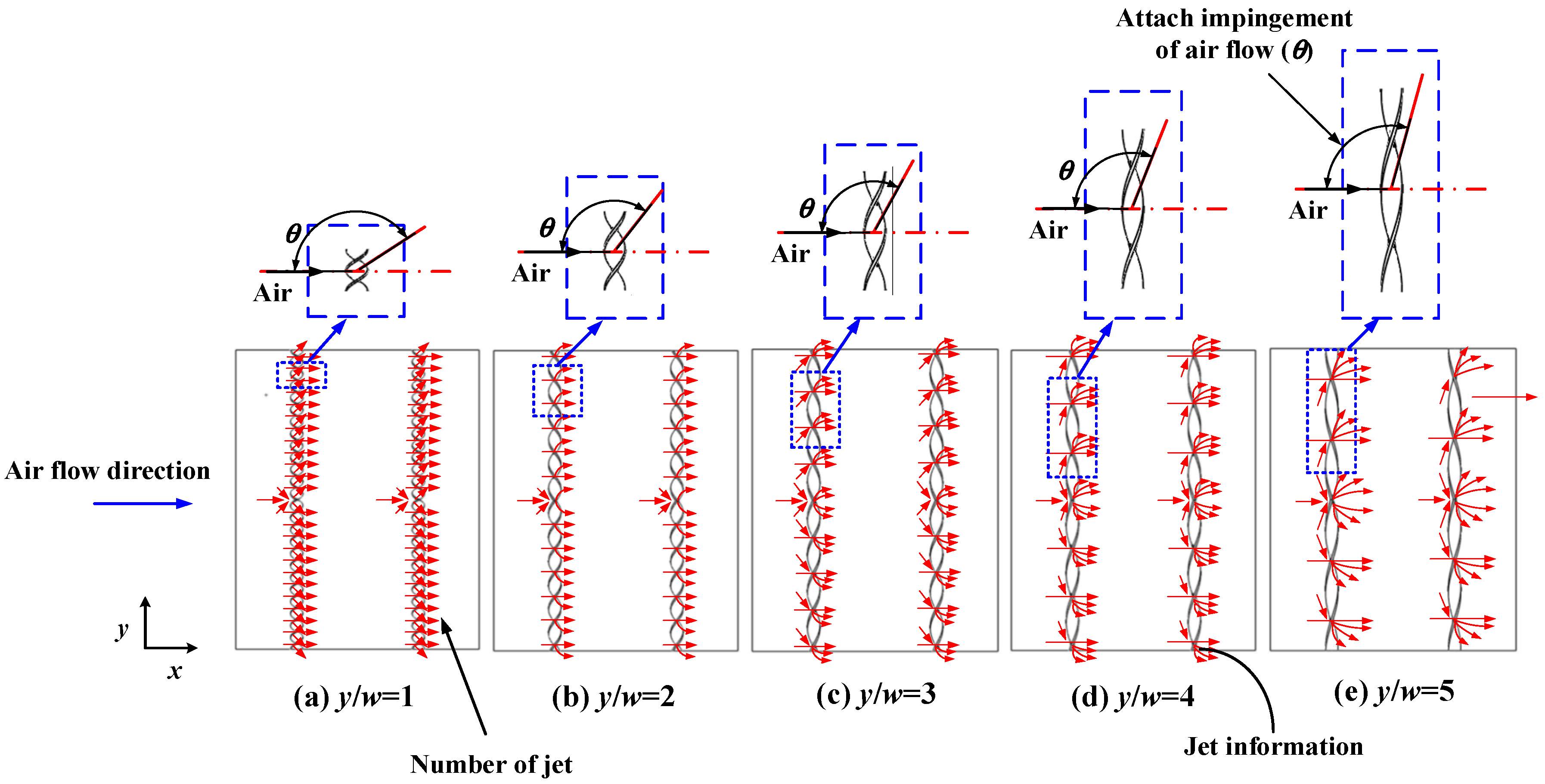
6.2. Effects of Twisted Ratio (y/w)
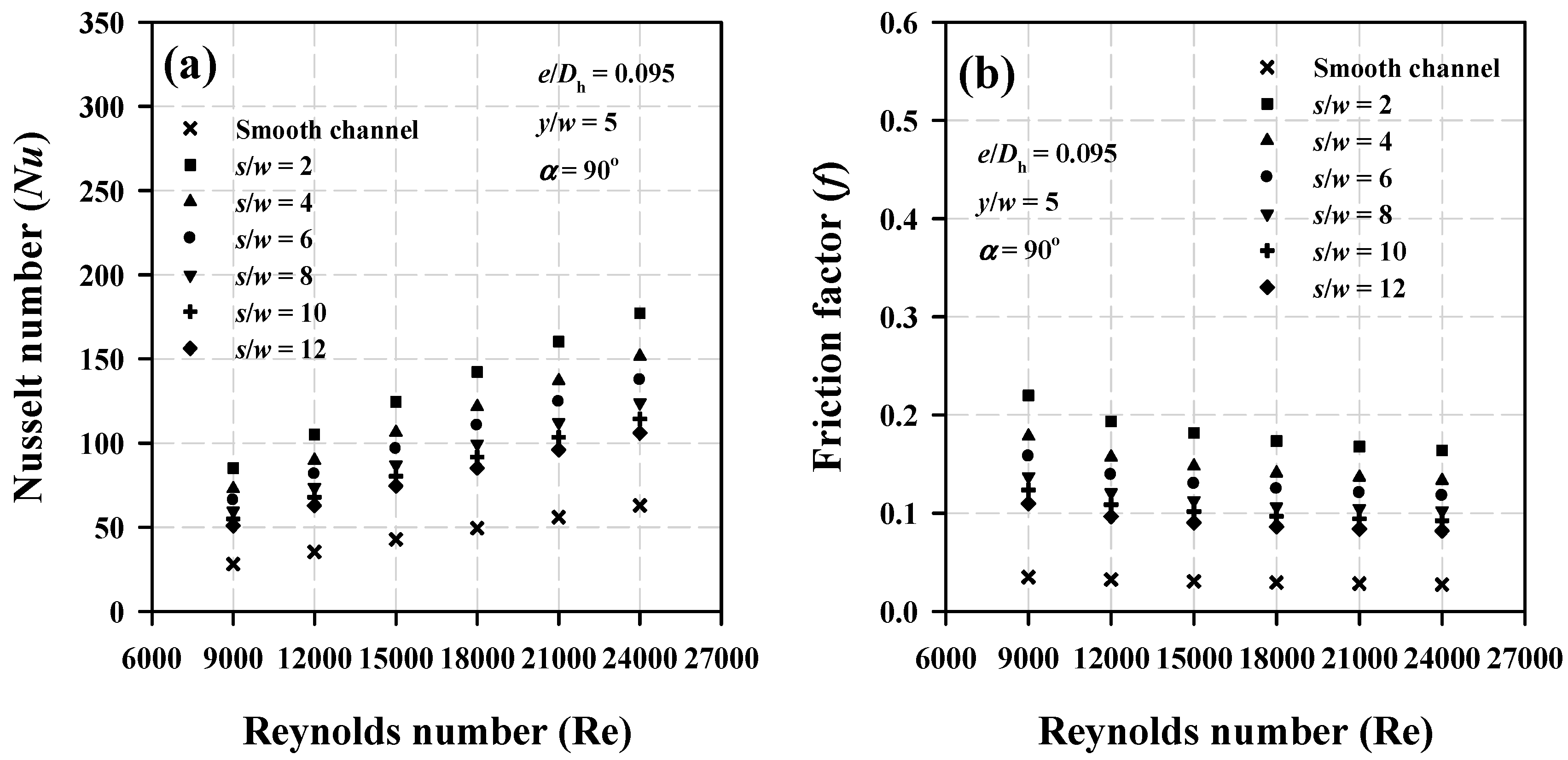
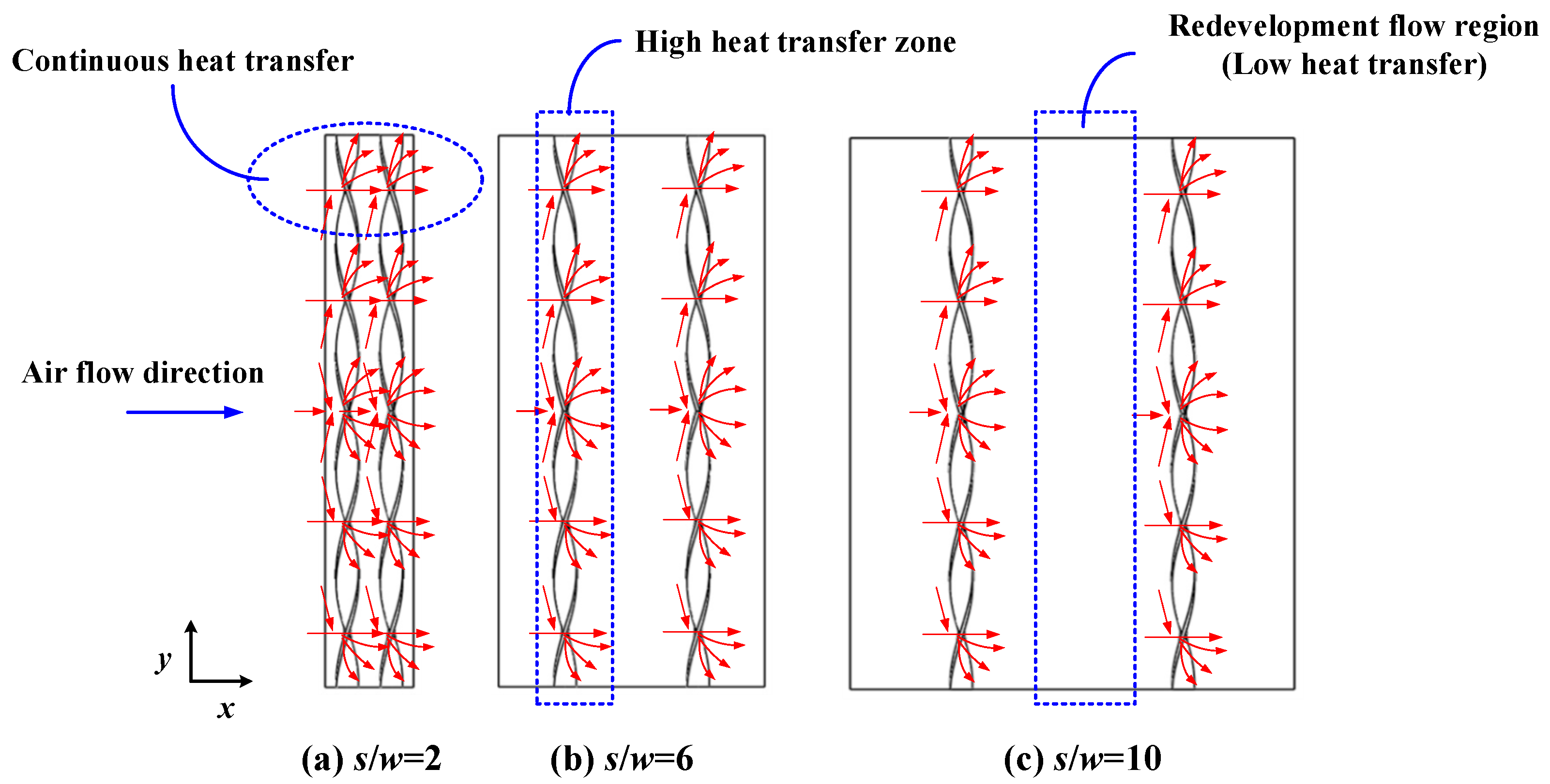
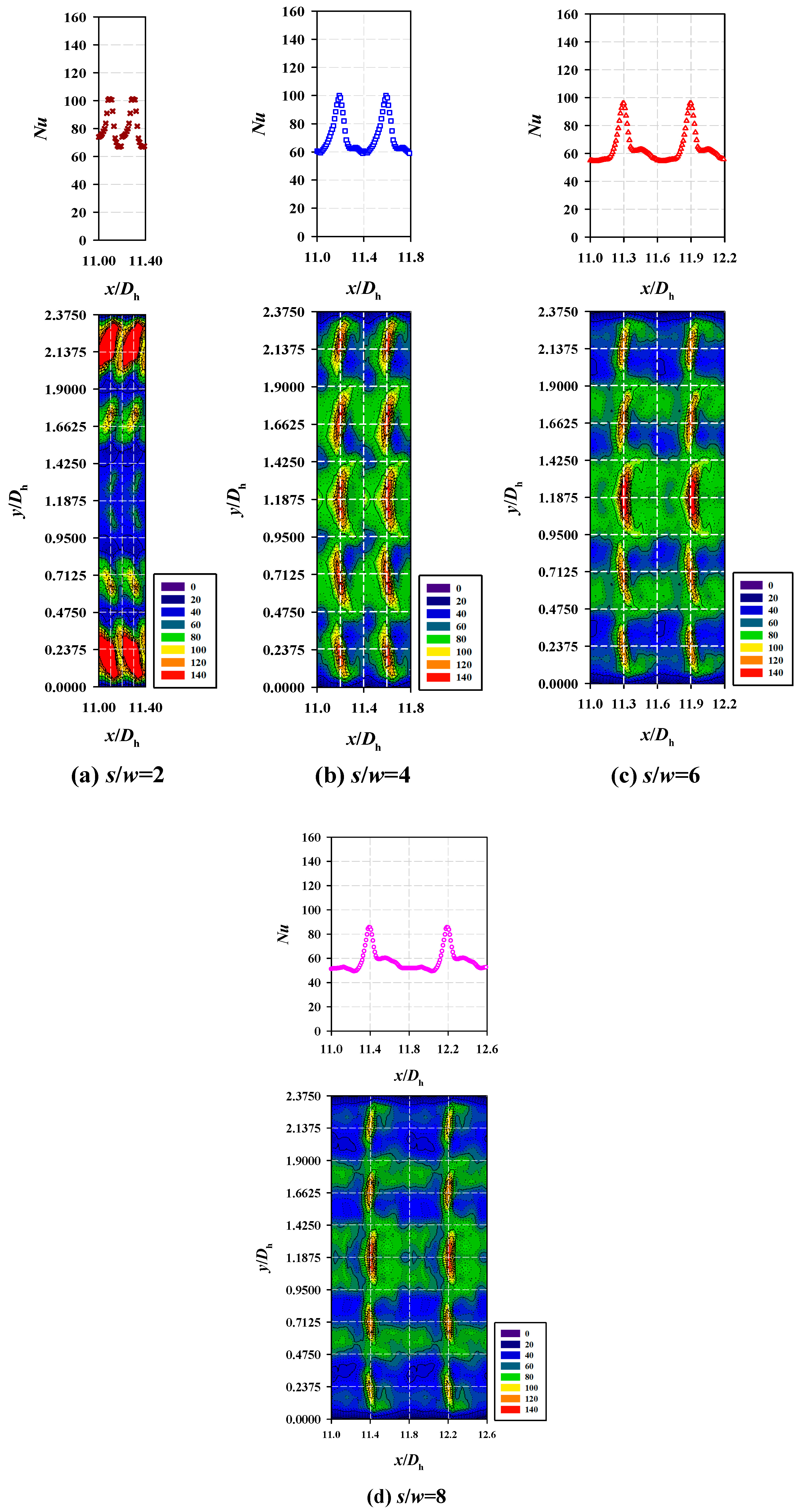
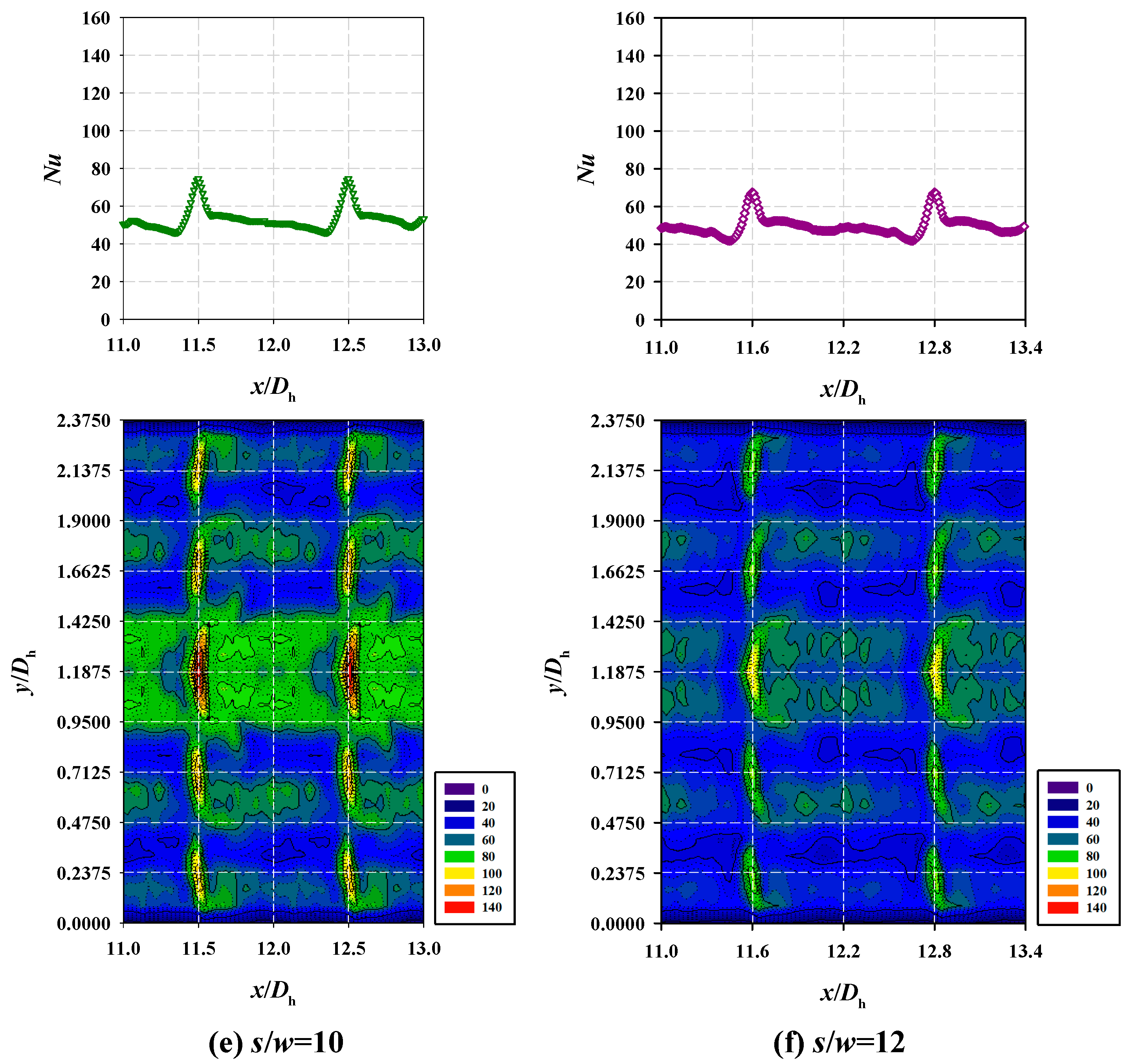
6.3. Effects of Free-Spacing Ratios (s/w)
6.4. Thermal Enhancement Factor (TEF)
6.5. Comparison with Previous Work
7. Conclusions
- The Nusselt number increased, while the friction factor decreased. The Reynolds number (Re) increased with the Nusselt number when the relative pitch ratio (s/w) decreased and when the twist ratio (y/w) increased. However, with the friction factor, there is a possibility that it decreased in value when the relative pitch ratio (s/w) increased and when the twist ratio (y/w) decreased.
- The highest values of the Nusselt number and friction factor were 2.99–3.16 times and 6.01–6.29 times higher than those of the smooth channels with alternate axis twisted baffles when s/w = 2 and y/w = 5, respectively.
- The optimal value of the thermal enhancement factor was 1.71 with a Reynolds number of 9000. The optimum roughness parameter (based on the TEF parameter criterion) was with a lower relative pitch ratio and higher twist ratio.
Author Contributions
Funding
Conflicts of Interest
Nomenclature
| A | area, m2 |
| c | specific heat, J kg−1 K−1 |
| C | coefficient of the orifice meter |
| d/w | gap of position ratio |
| D | diameter, m |
| e | height of baffle, m |
| e/D | relative blockage height |
| e/H | relative roughness height |
| f | friction factor |
| g/e | gap of width ratio |
| h | heat transfer coefficient, W m−2 K−1 |
| H | hue value |
| H | height of test channel, m |
| I | intensity value |
| k | thermal conductivity of fluid, W m−1 K−1 |
| l | width of twisted baffle, m |
| L | length of test section, m |
| mass flow rate, kg s−1 | |
| Nu | Nusselt number |
| P | free-spacing length, m |
| P | pitch length, m |
| P | static pressure, Pa |
| P/e | relative roughness pitch |
| ΔP | pressure drop, Pa |
| Pr | Prandtl number |
| Q | heat transfer rate, W |
| Re | Reynolds number |
| s | distance between the twisted baffle, m |
| s/w | relative pitch ratio |
| S | saturation value |
| t | thickness of twisted baffle, m |
| T | temperature, °C |
| U | average velocity, m s−1 |
| V | air velocity, m s−1 |
| V | voltage, V |
| w | height of twisted baffle, m |
| W | width of test section, m |
| x | local distance of the test section, m |
| y | pitch value of twisted baffle, m |
| y/w | twist ratio |
| Greek Symbols | |
| ρ | fluid density, kg m−3 |
| μ | fluid dynamic viscosity, kg s−1 m−1 |
| ν | kinematics viscosity, m2 s−1 |
| α | attack of angle, degrees |
| Subscripts | |
| abs | absorbed heat |
| b | bulk |
| bs | blue start |
| c | cross section |
| d | discharge |
| h | hydraulic |
| hs | heating surface |
| i | inlet |
| o | outlet |
| rs | red start |
| s | surface or smooth channel |
| w | wall |
| x | local distance of x-axis |
| Abbreviations | |
| AATB | alternate axis twisted baffle |
| AC | alternating current |
| ASME | American society for mechanical engineering |
| ANSI | American National Standard Institute |
| AR | aspect ratio |
| BR | blockage ratio |
| HSI | hue–saturation–intensity color system |
| MT-VG | multiple twisted tape vortex generator |
| PHE | plate heat exchanger |
| PLA | polylactic acid |
| PR | pitch spacing ratio |
| RGB | red–green–blue color system |
| RTD | resistance temperature detector |
| TB | transverse baffle |
| TEF | thermal enhancement factor |
| TLC | thermochromic liquid crystal |
| UHT | ultra-heat treatment |
References
- Wijayanta, A.T.; Aziz, M.; Kariya, K.; Miyara, A. Numerical study of heat transfer enhancement of internal flow using double-sided delta-winglet tape insert. Energies 2018, 11, 3170. [Google Scholar] [CrossRef]
- Sriharsha, V.; Prabhu, S.V.; Vedula, R.P. Influence of rib height on local heat transfer distribution and pressure drop in a square channel with 90° continuous and 60° V-broken ribs. Appl. Therm. Eng. 2009, 29, 2444–2459. [Google Scholar] [CrossRef]
- Liu, S.; Sakr, M. A comprehensive review on passive heat transfer enhancements in pipe exchangers. Renew. Sustain. Energy Rev. 2013, 19, 64–81. [Google Scholar] [CrossRef]
- Kumar, A.; Kim, M.-H. Thermal hydraulic performance in a solar air heater channel with multi V-type perforated baffles. Energies 2016, 9, 564. [Google Scholar] [CrossRef]
- Akpabio, E.; Oboh, I.; Aluyor, E.O. The effect of baffles in shell and tube heat exchangers. Adv. Mater. Res. 2009, 62–64, 694–699. [Google Scholar] [CrossRef]
- Rawat, D.S.; Jaurker, A.R. Enhancement of heat transfer using artificial roughness in solar air heater. Int. J. Eng. Sci. Invent. 2014, 3, 50–63. [Google Scholar]
- Kumar, C.N.; Murugesan, P. Review on twisted tapes heat transfer enhancement. Int. J. Sci. Eng. Res. 2012, 3, 1–9. [Google Scholar]
- Kukulka, D.J.; Smith, R. Enhancement heat transfer surface development for exterior tube surfaces. Chem. Eng. Trans. 2013, 32, 511–516. [Google Scholar]
- Fryer, P.J.; Robbins, P.T.; Green, C.; Schreier, P.J.R.; Pritchard, A.M.; Hasting, A.P.M.; Royston, D.G.; Richardson, J.F. A statistical model for fouling of a plate heat exchanger by whey protein solution at UHT conditions. Inst. Chem. Eng. 1996, 71, 189–199. [Google Scholar] [CrossRef]
- Zhang, J.; Zhu, X.; Mondejar, M.E.; Haglind, F. A review of heat transfer enhancement techniques in plate heat exchangers. Renew. Sustain. Energy Rev. 2019, 101, 305–328. [Google Scholar] [CrossRef]
- Promvonge, P.; Changcharoen, W.; Kwankaomeng, S.; Thianpong, C. Numerical heat transfer study of turbulent square-duct flow through inline V-shaped discrete ribs. Int. Commun. Heat Mass Transf. 2011, 38, 1392–1399. [Google Scholar] [CrossRef]
- Boonloi, A.; Jedsadaratanachai, W. Fluid dynamics and transport phenomena turbulent forced convection in a heat exchanger square channel with wavy-ribs vortex generator. Chin. J. Chem. Eng. 2015, 23, 1256–1265. [Google Scholar] [CrossRef]
- Prasad, B.N.; Saini, J.S. Effect of artificial roughness on heat transfer and friction factor in a solar air heater. Sol. Energy 1988, 41, 555–560. [Google Scholar]
- Aharwal, K.R.; Gandhi, B.K.; Saini, J.S. Experimental investigation on heat-transfer enhancement due to a gap in an inclined continuous rib arrangement in a rectangular duct of solar air heater. Renew. Energ. 2008, 33, 585–596. [Google Scholar] [CrossRef]
- Momin, A.M.E.; Saini, J.S.; Solanki, S.C. Heat transfer and friction in solar air heater duct with V-shaped rib roughness on absorber plate. Int. J. Heat Mass Transf. 2002, 45, 3383–3396. [Google Scholar] [CrossRef]
- Eiamsa-ard, S. Study on thermal and fluid flow characteristics in turbulent channel flows with multiple twisted tape vortex generators. Int. Commun. Heat Mass Transf. 2010, 31, 644–651. [Google Scholar] [CrossRef]
- Kumar, A.; Layek, A. Thermo-hydraulic performance of solar air heater having twisted rib over absorber plate. Int. J. Therm. Sci. 2018, 133, 181–195. [Google Scholar] [CrossRef]
- Stasiek, J.; Stasiek, A.; Jewartowski, M.; Collins, M.W. Liquid crystal thermography and true-colour digital image processing. Opt. Laser Technol. 2006, 38, 243–256. [Google Scholar] [CrossRef]
- Soodkaew, P.; Skullong, S.; Promvonge, P.; Pairok, W. Heat transfer enhancement in a solar air heater channel with discrete V-baffles. Adv. Mater. Res. 2014, 931–932, 1193–1197. [Google Scholar] [CrossRef]
- Mehta, B.; Khandekar, S. Measurement of local heat transfer coefficient during gas-liquid Taylor bubble train flow by infra-red thermography. Int. J. Heat Fluid Flow 2014, 45, 41–52. [Google Scholar] [CrossRef]
- Baughn, J.W. Liquid crystal methods for studying turbulent heat transfer. Int. J. Heat Fluid Flow 1995, 16, 365–375. [Google Scholar] [CrossRef]
- Grassi, W.; Testi, D.; Vista, D.D.; Torelli, G. Calibration of a sheet of thermosensitive liquid crystals viewed non-orthogonally. Measurement 2007, 40, 898–903. [Google Scholar] [CrossRef]
- Yan, W.M.; Liu, H.C.; Soong, C.Y.; Yang, W.-J. Experiment study of impinging heat transfer along rib-roughened walls by using transient liquid crystal technique. Int. J. Heat Mass Transf. 2005, 48, 2420–2428. [Google Scholar] [CrossRef]
- Abdullah, N.A.; Talib, R.A.; Jaafer, A.A.; Salleh, M.A.M.; Chong, W.T. The basics and issues of thermochromic liquid crystal calibrations. Exp. Therm. Fluid Sci. 2010, 34, 1089–1121. [Google Scholar] [CrossRef]
- Ower, E.; Pankhurst, R.C. Measurement of Air Flow, 5th ed.; Pergamon Press: Oxford, UK, 1977; (In SI units ed.). [Google Scholar]
- Agrawal, S.; Bhagoria, J.L.; Malviya, R.K. A detailed review on artificial roughness geometries for optimizing thermo-hydraulic performance of solar air heater. J. Mod. Eng. Res. 2014, 4, 106–122. [Google Scholar]
- Sharma, Y.; Rajotiya, A.; Kumar, R.; Prinam, A. A review of the effect of baffles geometry on heat transfer enhancement techniques. Int. J. Innov. Res. Sci. Technol. 2015, 2, 47–50. [Google Scholar]
- Promvonge, P. Heat transfer and pressure drop in a channel with multiple 60° V-baffles. Int. Commun. Heat Mass Transf. 2010, 37, 835–840. [Google Scholar] [CrossRef]
- An American National Standard, Measurement of Fluid Flow in Pipes Using Orifice, Nozzle and Venturi; ASME MFC-3M-2004; United Engineering Center: New York, NY, USA, 2004; pp. 1–56.
- Abernethy, R.B.; Benedict, R.P.; Dowdell, R.B. ASME Measurement Uncertainty. J. Fluid. Eng. 1985, 107, 161–164. [Google Scholar] [CrossRef] [Green Version]
- Alam, T.; Saini, R.P.; Saini, J.S. Experiment investigation on heat transfer enhancement due to V-shaped perforated blocks in a rectangular duct of solar air heater. Energy Convers. Manag. 2014, 81, 374–383. [Google Scholar] [CrossRef]
- Duffie, J.A.; Beckman, J.A. Solar Engineering of Thermal Processes, 3rd ed.; Wiley Inter Science Publications: New York, NY, USA, 1980. [Google Scholar]
- Bhuiya, M.M.K.; Chowdhury, M.S.U.; Shahabuddin, M.; Saha, M.; Memon, L.A. Thermal characteristics in a heat exchanger tube fitted with triple twisted tape inserts. Int. Commun. Heat Mass Transf. 2013, 48, 124–132. [Google Scholar] [CrossRef]
- Eiamsa-ard, S.; Promvonge, P. Enhancement of heat transfer in a circular wavy-surfaced tube with a helical-tape insert. Int. Energy J. 2007, 8, 29–36. [Google Scholar]
- Lee, D.H.; Rhee, D.-H.; Kim, K.M.; Cho, H.H.; Moon, H.K. Detailed measurement of heat/mass transfer with continuous and multiple V-shaped ribs in rectangular channel. Energy 2009, 34, 1770–1778. [Google Scholar] [CrossRef]
- Promvonge, P.; Thianpong, C. Thermal performance assessment of turbulent channel flows over different shaped ribs. Int. Commun. Heat Mass Transf. 2008, 35, 1327–1334. [Google Scholar] [CrossRef]
- Albaldawi, R.A.H.; Shyaa, A.K.; Al-Ameer, S.A. Experimental investigation for enhancement heat transfer in a channel with angle-ribbed tape at various attack angle. J. Eng. Sustain. Dev. 2017, 21, 163–179. [Google Scholar]
- Karwa, R.; Solanki, S.C.; Saini, J.S. Thermo-hydraulic performance of solar air heaters having integral chamfered rib roughness on absorber plates. Energy 2001, 26, 161–176. [Google Scholar] [CrossRef]
- Promvonge, P.; Khanoknaiyakarn, C.; Kwankaomeng, S.; Thianpong, C. Thermal behavior in solar air heater channel fitted with combined rib and delta-winglet. Int. Commun. Heat Mass Transf. 2011, 38, 749–756. [Google Scholar] [CrossRef]
- Singh, S.; Chander, S.; Saini, J.S. Heat transfer and friction factor of discrete V-down rib roughened solar air heater ducts. J. Renew. Sustain. Energy 2011, 3, 013108. [Google Scholar] [CrossRef]
- Sriromreun, P.; Sriromreun, P. Numerical study on heat transfer enhancement in a rectangular duct with V-shaped ribs. Chem. Eng. Trans. 2018, 70, 1285–1290. [Google Scholar]


| No. | Instruments | Description | Specification |
|---|---|---|---|
| 1 | Nikon DSLR D5100 | take TLC surface pictures | effective pixels: 16.2 million |
| camera | (4928 × 3264 pixels for large size) | ||
| 2 | TLC sheet | temperature indicating sheet | accuracy: ±0.1 °C, |
| (heating surface) | 30–35 °C (86–95 °F) | ||
| 3 | RTD Pt100 | temperature sensor | accuracy: ±0.001 Ώ at 0 °C |
| (inlet and outlet temperature) | (−130 to +95 °C ±0.05 °C) | ||
| 4 | TSI/Alnor 9565-A | air velocity measurement | accuracy: ±3% for reading |
| thermo-anemometer | (±0.015 m/s), range: 0–50 m/s | ||
| resolution: 0.01 m/s | |||
| 5 | Dwyer MS-111 | differential pressure sensor | accuracy: ±2% for 250 Pa, |
| (orifice meter) | ±1% for 250–1250 Pa | ||
| 6 | Dwyer DM-2004 | differential pressure sensor | accuracy: ±1% full scale at 70 °C |
| (test section) | |||
| 7 | HIOKI LR8401 | temperature recorder | 10 ms high-speed sampling |
| data logger | (with 30-channel as standard) |
| No. | Parameter | Range |
|---|---|---|
| 1 | Reynolds number (Re) | 9000–24,000 (six values) |
| 2 | Relative blockage height (e/Dh) | 0.095 (one value) |
| 3 | Relative pitch ratio (s/w) | 2–12 (six values) |
| 4 | Twist ratio (y/w) | 1–5 (five values) |
| 5 | Angle of attack (α) | 90° (one value) |
| Researcher | Roughness | Operating Condition | TEF |
|---|---|---|---|
| Momin et al. [15] | V-shaped ribs | Re = 2500–18,000, P/e = 10, α = 30–90°, W/H = 10.15, e/Dh = 0.02–0.034 | 1.76 |
| Eiamsa-ard [16] | Multiple twisted tapes | Re = 2700–9000, AR = 10, y/w = 2.5–3.5, s/w = 1.0–1.66 | 1.41 |
| Promvonge [28] | Multiple 60° V-baffles | Re = 5000–25,000, AR = 10, e/H = 0.1–0.3, PR = 1–3 | 1.87 |
| Albaldawi et al. [37] | Angle-ribbed tape | Re = 3400–20,800, α = 10–90°, BR = 0.2, PR = 1 | 1.30 |
| Singh et al. [38] | Discrete V-down ribs | Re = 3000–15,000, AR = 12, d/w = 0.2–0.8, P/e = 10, e/Dh = 0.043, α = 60° | 2.03 |
| Karwa et al. [39] | Chamfered ribs | Re = 3750–16,350, φ = 15°, P/e = 4.58–7.09, AR = 6.88–9.38, e/Dh = 0.0197–0.0441 | 1.39 |
| Promvonge et al. [40] | Combined rib and delta-winglet | Re = 5000–22,000, α = 30–60°, e/H = 0.2, b/H = 0.4, Pt/H = 1, Pl/H = 1.33 | 1.38 |
| Sriromreun et al. [41] | Multiple V-ribs with combined staggered ribs | Re = 12,681–35,000, α = 30°, e/H = 0.1–0.3 | 2.05 |
| The present study | Alternate axis twisted baffles | Re = 9000–24,000, AR = 3.75, s/w = 2–12, e/Dh = 0.095, y/w = 1–5, α = 90° | 1.71 |
© 2019 by the authors. Licensee MDPI, Basel, Switzerland. This article is an open access article distributed under the terms and conditions of the Creative Commons Attribution (CC BY) license (http://creativecommons.org/licenses/by/4.0/).
Share and Cite
Phila, A.; Thianpong, C.; Eiamsa-ard, S. Influence of Geometric Parameters of Alternate Axis Twisted Baffles on the Local Heat Transfer Distribution and Pressure Drop in a Rectangular Channel Using a Transient Liquid Crystal Technique. Energies 2019, 12, 2341. https://doi.org/10.3390/en12122341
Phila A, Thianpong C, Eiamsa-ard S. Influence of Geometric Parameters of Alternate Axis Twisted Baffles on the Local Heat Transfer Distribution and Pressure Drop in a Rectangular Channel Using a Transient Liquid Crystal Technique. Energies. 2019; 12(12):2341. https://doi.org/10.3390/en12122341
Chicago/Turabian StylePhila, Arnut, Chinaruk Thianpong, and Smith Eiamsa-ard. 2019. "Influence of Geometric Parameters of Alternate Axis Twisted Baffles on the Local Heat Transfer Distribution and Pressure Drop in a Rectangular Channel Using a Transient Liquid Crystal Technique" Energies 12, no. 12: 2341. https://doi.org/10.3390/en12122341